1
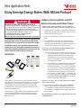
Veris Application Note
N55
Using Enercept Energy Meters With BACnet Protocol
Configuring an Enercept Meter and a BAS
Remote for Operation with BACnet Protocol
DANGER
HAZARD OF ELECTRIC SHOCK, EXPLOSION, OR ARC FLASH
•
•
•
•
•
Follow safe electrical work practices. See NFPA 70E in the USA, or applicable local codes.
This equipment must only be installed and serviced by qualified electrical personnel.
Read, understand and follow the instructions before installing this product.
Turn off all power supplying equipment before working on or inside the equipment.
Use a properly rated voltage sensing device to confirm power is off.
DO NOT DEPEND ON THIS PRODUCT FOR VOLTAGE INDICATION
• Only install this product on insulated conductors.
Failure to follow these instructions will result in death or serious injury.
The information provided herein is intended to supplement the
knowledge required of an electrician trained in high voltage
installations. There is no intent to foresee all possible variables
in individual situations, nor to provide all training needed to
perform these tasks. The installer is ultimately responsible to
assure that a particular installation will be and remain safe and
operable under the specific conditions encountered.
Introduction
Use of the BACnet communication protocol is increasing in building automation
systems applications. Veris Enercept H8035 and H8036 meters are an excellent option
for monitoring energy consumption, but their communication link uses Modbus
protocol, not BACnet. A new product called the BAS Remote (model BASR-8M),
created by Contemporary Controls, allows easy integration of H803x Enercept power
meters with existing BACnet devices.
VN55 Page 1
©VERIS INDUSTRIES 2011
b. Use the instructions in the User Manual to set the IP address, subnet mask and
gateway (if used). The installer can also set names (description, location, etc.)
for the system and the unit used (optional).
c. Connect power to the BAS Remote according to the instructions in the User
Manual.
d. Connect the BAS Remote to the network. Ensure that the network drop
is active and is connected to the proper subnet (i.e. If the subnet mask is
255.255.255.0 and the assigned IP address is xxx.xxx.154.xxx [where xxx can
be any value], the device needs to be connected to subnet 154).
2. Create a <bas_cfg.csv> file with the desired Modbus to BACnet gateway
configuration. Use either of the following methods:
i. If connecting a single Enercept to the BAS Remote (with no other Modbus
devices), use the sample <bas_cfg.csv> file from the corresponding
Sample Project folder provided (either the “Veris H8035 – Single
Power Meter Project” folder or the “Veris H8036 – Single Power
Meter Project” folder). If these folders are not available, contact Veris
technical support at 800.345.8556
ii. If connecting multiple devices to the BAS Remote (either multiple Enercept
meters or one meter and other devices), follow the instructions in
the BAS Remote User Manual to a create a new project and build the
<bas_cfg.csv> file for the configuration required. When adding an
Enercept meter to the project as a new device, the Project Builder asks
for a “Modbus Device Profile.” Point the browser to the appropriate
Veris Profile (either <Veris H8035_M2B.xls > or <Veris H8036_M2B.
xls >). These files are posted on the Contemporary Controls website at
www.ccontrols.com/basautomation/m2bsoft/ and are available
from Veris technical support at 800.345.8556
BASR-8M
The BAS Remote acts as a Modbus-to-BACnet IP gateway. Multiple Enercept meters
can operate with a single BAS Remote, reducing commissioning costs for large
projects. Note that the BAS Remote does not provide a gateway from Modbus to
BACnet MS/TP (serial).
1. Configure network settings on the BAS Remote for your network. This
requires a fixed IP address, which may need to be assigned by IT personnel.
3. Transfer the <bas_cfg.csv> file to the “/data/config/” directory on the BAS
Remote using an FTP client.
Use the native FTP client on a Windows XP computer (from the COMMAND
prompt) or download a Windows-based utility (there are many good free
ones – like FileZilla). Accessing the file system on the BAS Remote requires a
user name and password; the default user name is “admin” and the default
password is “ctrlink.”
4. Reset the BAS Remote by turning its power supply off, waiting a few seconds,
and turning it back on.
800.354.8556 or +1.503.598.4564
08111
HQ0000432.B
5. Configure the BACnet parameters on the BAS remote.
a. Follow the instructions in the BAS Remote User Manual to access the BAS
Remote’s webpage (by entering the IP address in a web browser on the same
network).
b. Set the Device Instance to the preferred value. This must be a value that is
unique for the overall BACnet enterprise.
6. Configure the Modbus parameters on the BAS remote.
a. Follow the instructions in the BAS Remote User Manual to access the BAS
Remote’s webpage (by entering the IP address in a web browser on the same
network).
b. Set the Baudrate to 9600. This is the only rate the Enercept H803x can use.
c. Set the Parity to NONE. This is the only value the Enercept H803x can use.
7. Configure the Enercept (and other Modbus devices, if applicable).
a. Install and power the Enercept according to the Installation Guide.
b. Connect the Modbus RTU signals of the Enercept to the MB inputs on the BAS
Remote. Refer to the instructions in the Installation Guides for all devices and
the BAS Remote.
c. Set the Modbus addresses to match those set up in the gateway project. If
using one of the <bas_cfg.csv> files pre-configured for a single Enercept
device, the Modbus address must be 10. The BAS Remote reserves all Modbus
addresses below 10 for internal I/O devices.
d. If using any other devices on the same Modbus link with Enercept meters, set
their Baud rates to 9600 and their Parity to NONE.
8. Use BACnet software to access the Enercept H803x meter.
a. The Device Instance set in Step 3 refers to the BAS Remote.
b. All data objects set up in the gateway project are referenced using this Device
Instance (the individual Modbus meters or other devices do not have separate
Device Instances).
c. The Object Instance numbers assigned are a concatenation of three decimal
values:
i. The Modbus address (2 decimal digits),
ii. The decimal value 40,
iii. The decimal value of specific Modbus register address in the device.
(for example, if the Modbus address is 10, Modbus Register 259 is referenced
by the BACnet Analog_Input object instance #1040259
d. The Object Instances for the data objects that access the Modbus registers
of all the Modbus devices in the project are documented in the spreadsheet
whose file name ends with “Documention” (yes, that’s how it is spelled).
Figures 1 and 2 show the contents of those files for the example projects
provided (for a single Enercept at Modbus address 10).
Figure 1: Object List for the Single H8035 Example (at Modbus Address 10)
Figure 2: Object List for the Single H8036 Example (at Modbus Address 10)
VN55 Page 2
©VERIS INDUSTRIES 2011
800.354.8556 or +1.503.598.4564
08111
HQ0000432.B
e. Since the BACnet objects reside in the BAS Remote, not in the individual
devices, they can be discovered and read even if the Enercept or other Modbus
devices are not communicating (i.e. if they are not connected, not powered,
or not set up properly). If the Modbus device fails to communicate, the values
read from these objects will either be initial values (usually zeros) established
when the objects were initialized, or they will be the last known values
read from the device operating at some prior time. To verify the devices
are operating correctly before relying on the data, check the Status_Flags
Property immediately prior to reading the Present_Value; if a device is not
operating properly, the Status_Flag reports a fault.
f. The BAS Remote polls all configured Modbus registers at regular intervals,
set by the Offline Poll Period setting in the Modbus tab of the web-based
configuration page. The default value is 15000 msec, which corresponds to a
15 seconds polling interval.
g. While the Analog_Input objects created by the BAS Remote support a number
of properties, the most useful are PRESENT_VALUE, UNITS and STATUS_
FLAGS. Properties supported are:
i. OBJECT_IDENTIFIER: the object type and instance # (i.e. AI1040259)
ii. OBJECT_NAME (i.e. H8035-1 Energy Consumpt 1040259)
iii. OBJECT_TYPE (i.e. Analog_Input)
iv. PRESENT_VALUE: the value polled from the mapped register in the
Modbus device
The customer must also re-configure the software when there is a change to the
equipment used. When any Modbus devices are added or changed, the software
must be updated with the new mapping of all Modbus registers.
Device Object
Products with native BACnet support each have their own Device Object, and they
generally support additional BACnet features, making them easier to program
and maintain. The Device Object uniquely identifies the type, name, description,
manufacturer, version, location, characteristics and capabilities of each device. When
using more than one device of the same model, each device holds a unique Device
Object. These products may be tested and certified (not all are) by BTL (BACnet
Testing Laboratories) as BTL-compliant.
Modbus products used with a BACnet gateway do not have unique Device Objects.
The Gateway is a single Object, and all Modbus devices on that serial link share that
Object. The gateway may be tested and certified as BTL compliant (most are not), but
the Modbus devices used with the gateway are not compliant.
Some customers want to connect their meter to a BACnet MS/TP serial link, rather
than an Ethernet drop using BACnet IP. Even though many BACnet applications
utilize BACnet IP over Ethernet at some point in the system, they may have a serial
cable near the location where the meter is installed or be more willing to extend
an existing MS/TP loop to that location than to add an Ethernet drop and a fixed IP
address for one or more meters. Serving these applications requires a Modbus RTU to
BACnet MS/TP gateway, rather than a BAS Remote.
Data Object
v. DESCRIPTION: implemented, but returns “Default channel description”
vi. STATUS_FLAGS: this indicates the status of the polled object (will indicate
“FAULT” if the Modbus device did not respond to the most recent poll)
vii. EVENT_STATE: implemented, but usually reports “NORMAL”
viii. OUT_OF_SERVICE: implemented, but does not indicate if the Modbus
device is out of service
Each product with native BACnet support contains a unique set of data objects
accessible through customer software. If multiple units are used on the same
network, they each operate identically and independently, making it easy to
integrate more. Software that accesses these products need only be touched once to
add a device to the network.
Modbus products used with a BACnet gateway have data objects resident in the
gateway that get mapped to their individual Modbus registers. If multiple units
are used on the same network, they must be numbered uniquely across all units.
The objects exist in the gateway even if the physical product is not present or is not
operating properly (see 8e above).
ix. UNITS: indicates the units associated with the Present_Value (Volts,
Amps, kWh, Power Factor, etc.) of each object
x. COV_INCREMENT: not used for polled objects (default is 999999.9)
Innovative Monitoring Solutions
Modbus Devices with a Gateway vs. BACnet
Devices
The BAS Remote Modbus-to-BACnet gateway allows more options for peripheral
monitoring devices. Instead of being confined only to those devices equipped with
the BACnet communication protocol, a facility administrator can now incorporate
Modbus devices into a BACnet-networked building. The Enercept power meter with
the BAS Remote is an excellent choice for easy integration into existing systems.
When using Modbus devices with a BACnet gateway, extra steps might be needed to
ensure seamless integration with a BACnet system.
Installation of the gateway and the power supply (or transformer) in addition to
the power meter increase cost and labor. Installing multiple meters with a shared
gateway reduces the additional cost for the device, but the effort to commission them
might increase with the gateway configuration complexity.
A Modbus-to-BACnet gateway also requires a custom-built gateway configuration
(the bas_cfg.csv file) for each unique application. This configuration must be
re-built and re-downloaded into the gateway each time new devices are added.
The gateway vendor provides documentation, profile templates, technical support,
and a spreadsheet-based tool to simplify this. Veris Industries has collaborated
with Contemporary Controls to build and test these templates and to make them as
consistent as possible with other Veris products that have native BACnet support.
Veris also provides direct technical support for the Modbus-to-BACnet systems.
VN55 Page 3
©VERIS INDUSTRIES 2011
800.354.8556 or +1.503.598.4564
08111
HQ0000432.B