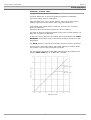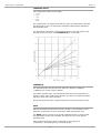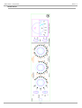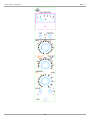
1
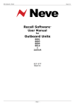
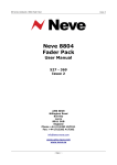
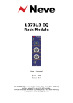
2264
Limiter
Compressor
User Manual
527 – 394
Issue 1.4
2264 Limiter / Compressor
Issue 1.4
Health & Safety Notice
For your own safety and for the protection of others,
please observe the following safety precautions:
•
Read these instructions.
•
Keep these instructions.
•
Follow all instructions.
•
Only use attachments/accessories specified by the manufacturer.
•
Heed all safety warnings.
•
Do not use near water.
•
Clean only with a dry cloth.
•
Do not install near heat sources.
•
Do not block ventilation openings.
•
Unplug when unused for long periods of time.
•
Refer all servicing to qualified personnel only.
AMS Neve
Billington Road
Burnley
Lancs
BB11 5UB
England
Phone +44 (0)1282 457011
Fax: +44 (0)1282 417282
Info: [email protected]
Web: www.ams-neve.com
Support: http://www.ams-neve.com/support
© 2013 AMS Neve Ltd own the copyright of all information and drawings contained in this manual which are not to be copied or
reproduced by any means or disclosed in part or whole to any third party without written permission.
As part of our policy of continual product improvement, we reserve the right to alter specifications without notice but with due regard to
all current legislation.
Disclaimer: The information in this manual has been carefully checked and is believed to be accurate at the time of publication.
However, no responsibility is taken by us for inaccuracies, errors or omissions nor any liability assumed for any loss or damage
resulting either directly or indirectly from use of the information contained within it.
Trademarks: All trademarks are the property of their respective owners and are hereby acknowledged.
-2-
2264 Limiter / Compressor
Issue 1.4
Table of Contents
Health & Safety Notice........................................................................................2
Introduction........................................................................................................4
Front Panel Controls............................................................................................5
LIMIT IN / OUT..................................................................................................5
COMPRESS IN /OUT...........................................................................................5
BYPASS / IN......................................................................................................5
A / IND / B........................................................................................................5
LIMIT THRESHOLD..............................................................................................5
LIMIT RECOVERY................................................................................................5
COMPRESS THRESHOLD......................................................................................5
COMPRESSION RECOVERY...................................................................................5
GAIN MAKE UP...................................................................................................5
RATIO COMPRESS..............................................................................................5
Meter................................................................................................................5
Rear Panel Controls.............................................................................................6
Preset Gain........................................................................................................6
Meter Preset......................................................................................................6
Limiter Preset....................................................................................................6
Modules In Transit..............................................................................................6
2264 Operation..................................................................................................7
LIMITING – ATTACK TIME....................................................................................7
COMPRESS RATIO..............................................................................................8
THRESHOLD......................................................................................................8
GAIN................................................................................................................8
Limiter & Compressor in combination....................................................................9
BYPASS Switch...................................................................................................9
A / IND / B........................................................................................................9
Presets..............................................................................................................9
Unit Specifications............................................................................................10
Recall sheets....................................................................................................11
In the unlikely even that this unit should malfunction or develop a
fault, then please register the fault details on our website, by
clicking the link below.
You will also need to enter the unit's serial number when you do
this, so please have this to hand.
http://www.ams-neve.info/crm/fault_report.html
Once the fault details have been registered, one of our technical
support team will be in touch via email.
This link should also be used for further operational or technical
help, or any general enquiry about the unit.
-3-
2264 Limiter / Compressor
Issue 1.4
Introduction
The 2264 Limiter / Compressor facilities and performance are similar
to those of a 2254/R Limiter Compressor.
The main advantages of the 2264 are it's smaller size, plus it uses a more
advanced circuit technique, and the response curves it produces are more
precise than those of a 2254/R.
The 2264 Limiter / Compressor has been designed for use in sound
broadcast and recording studios where a requirement exists for a high
quality instrument for the control of programme dynamic range.
The unit may also be used for the protection of transmitters from
overloading when the limiter is adjusted for a shorter attack time.
The operational controls and meter are mounted on the front panel of the
unit, and there are two preset potentiometers on the rear panel.
It comes as either a vertical or horizontal rack mount unit, but the
operation of both types of unit is identical.
-4-
2264 Limiter / Compressor
Issue 1.4
Front Panel Controls
LIMIT IN / OUT
Toggle switch.
Set the switch down to place the Limiter in circuit.
COMPRESS IN /OUT
Toggle switch.
Set the switch down to place the Compressor in circuit.
BYPASS / IN
This Bypass key connects the Input directly to the Output, in effect
bypassing all of the unit's circuitry.
A / IND / B
This 3-position toggle switch selects where the control voltage is to be
derived from: either internally (IND) or externally connected to one of
two control voltage ganging positions (A or B).
LIMIT THRESHOLD
Switched attenuator, from +4 dBm to +15dBm
LIMIT RECOVERY
Switched attenuator, notched settings from 50ms to 800 ms.
COMPRESS THRESHOLD
Switched attenuator from -20 dBm to +10 dBm.
COMPRESSION RECOVERY
Switched attenuator, notched settings from 50ms to 800 ms.
GAIN MAKE UP
Switched attenuator, runs from 0 dBm to +20 dBm.
RATIO COMPRESS
Switched attenuator, runs from 1.5:1 to 6:1 in notched increments.
Meter
Shows the amount of Gain Reduction being applied to the signal, and has
a PPM characteristic.
-5-
2264 Limiter / Compressor
Issue 1.4
Rear Panel Controls
Preset Gain
This gives +/- 2dB to the input to the compression sidechain.
Meter Preset
This meter preset, mounted on the printed circuit board is used in
calibrating the response of the meter at known levels of gain reduction.
Limiter Preset
This is used to set the onset of limiting to take place at +8 dBm.
Modules In Transit
Please note that the designs of the AMS Neve classic modules and racks
are to the original Neve specifications and are not designed to withstand
transit.
Should you wish to move the rack from one location to another (for
example shipping to another studio location or returning the rack to a
repair center for servicing), please remove all installed modules from the
rack and package the rack and each module separately in packaging
suitable to withstand the intended transit.
If modules are installed in a rack while in transit, damage to the internal
edge connectors may occur.
-6-
2264 Limiter / Compressor
Issue 1.4
2264 Operation
LIMITING – ATTACK TIME
This gives a limiting attack time of 4msec.
This slow attack time is used on programme material of moderately
percussive nature, such as a solo piano.
With this attack time a very narrow dynamic range can be achieved by
feeding high levels into the limiter while using a low limit level.
A fast attack time is desireable for example, when the unit is used for
driving a transmitter.
Fast attack times should be used with care when recording.
The point at which the limiting threshold occurs can be varied between +4
dBm and +15 dBm in 0.5dB steps.
A range of recovery times for the limiting action is provided by the LIMIT
RECOVERY control which may be selected according to the nature of the
programme.
The AUTO position is used where automatic corrective action is preferred.
This provides a composite control, with rapid response to isolated peaks
and a slower recovery after prolonged high levels.
The figure below shows the relationship between input and output levels
with the LIMIT LEVEL set at +4 dBm and +12 dBm.
-7-
2264 Limiter / Compressor
Issue 1.4
COMPRESS RATIO
Five compression ratios are provided:
• 1.5:1
• 2:1
• 3:1
• 4:1
• 6:1
The characteristic is shaped such that the onset of compression is smooth
and progressive, the true ratio being established within about 6dB above
the threshold point.
The graph below shows the relationships between input and output levels
for each of the five ratios, with THRESHOLD set to -20 dBm.
THRESHOLD
The threshold point may be varied in steps of 2 dB from -20dBm to
+10dBm giving a wide range of effects.
Low ratios operated from a low threshold will preserve the impression of
dynamic range while enabling the operator to achieve a significantly better
signal-to-noise ratio when recording.
A high ratio operated from a high threshold gives a partial limiting action.
GAIN
When a threshold point below line level is chosen, it is necessary to add
gain after compression so as to restore the mean programme level.
The GAIN control provides up to 20 dB of additional gain in steps of 2dB,
and gain added in this way inevitably increases the level of all signals
including noise.
Care should therefore be taken in attempting high degrees of
compression, necessitating large increases of gain.
-8-
2264 Limiter / Compressor
Issue 1.4
Limiter & Compressor in combination
When both of the LIMIT and COMPRESS switches are set to IN, the
sidechains controlling limiting and compressing will be operative.
Under these conditions, the compressor is effective below +8dBm only,
because at this point, the limiting action will take over complete control.
BYPASS Switch
When the BYPASS switch is set to the IN position, this effectively joins
the input and the output together, with the unit out of circuit.
NB:
When the source from which the instrument is fed has a significant
impedance, the output level may change when the BYPASSS key is
operated, particularly if the output circuit is terminated.
This effect arises because the unit constitutes a buffer amplifier having a
high input and low output impedance.
The limiter / compressor may be used as a linear amplifier providing both
the LIMIT and COMPRESS switches are set to OUT.
A / IND / B
Enables the control voltage to be derived either internally or can be
externally connected to one of two control voltage ganging positions.
Positions A & B of the switch select these buses, while the central position
selects the internal control voltage.
Each module has an A and a B switch setting, so each unit can be
assigned to one of two separate busses.
Once two or more units are assigned to this common buss, then it is the
loudest signal in this group that causes all compressors in that group to
action.
Please note that the units would need to be housed in an AMS Neve rack,
as the AMS Neve rack has this extra wiring needed to form these two
busses.
The unit can also work in ‘standalone’ mode, where you set the switch to
IND, and the unit will action to it’s own internal independent threshold.
Presets
The SET +8 preset mounted on the rear panel enables the limiting
threshold to be adjusted to the nominal level of +8dBm.
The RV1 preset (also mounted on the rear panel) is for setting the
compression threshold (nominally set at -16dBm)
NB:
Both of these presets should always be set under actual load conditions.
-9-
2264 Limiter / Compressor
Issue 1.4
Unit Specifications
General
Input
Output
10,000 Ω, bridging, balanced and earth-free.
Balanced and earth-free.
Maximum output into 600 Ω: 26 dBm.
Gain
Nominally 0 dBm, with +/- 2dB gain variation available by means of a preset
potentiometer mounted on the module rear panel.
Compress & Limit thresholds are defined in relation to the output level when terminated
to 600 Ω.
Bypass switch
In the OUT position, the output terminals are connected to the input terminals directly.
Control Voltage
Ganging Switch
Enables the control voltage to be derived either internally or can be externally connected
to one of two control voltage ganging positions.
Positions A & B of the switch select these buses while the central position selects the
internal control voltage.
Noise
Measured between 20Hz and 20kHz.
RMS output noise does not exceed -75dBm with no gain make up, or -55dBm with 20dB
of gain make up applied (only when COMPRESS is selected).
Frequency
Response
Relative to 1kHz, response is within +0, -0.5dB over range of 20Hz to 20kHz
Distortion
Measured at 1kHz, distortion does not exceed the following:
a) COMPRESS & LIMIT switched OUT, output level at +9dBm: 0.05%
b) COMPRESS switched IN, ratio 6:1, recovery 800ms, output level +9dBm: 0.2%
c) LIMIT switched IN, recovery 800ms, input level +20dBm, threshold +4dBm: 0.4%
Parameters
Limit Threshold
Limit Ratio
Limit Attack
Time
Limit Recovery
Time
Variable from +4dBm to +15dBm in 0.5dB steps.
Not less than 100:1.
4ms, measured by increasing the input level 10dB, and measuring the time taken for the
output level to decay 1dB above the limit threshold level.
Six recovery times are available:
50ms / 100ms / 200ms / 800ms / Auto 1 (100ms/2 sec) / Auto 2 (50ms/5 sec)
Compression
Ratio
Five ratios are available:
1.5:1 / 2:1 / 3:1 / 4:1 / 6:1
Compression
Threshold
Variable from -20dBm to +10dBm in 2dB steps
Compressor
Attack Time
3ms, measured by increasing the input level 10dB, and measuring the time taken for the
output level to decay to 1db above the limit threshold level.
Compressor
Recovery Time
Six recovery times are available:
100ms / 400ms / 800ms / 1.5 secs / Auto 1 (100ms/2 sec) / Auto 2 (50ms/5 sec)
Gain Make Up
Gain make up control provides 0 to 20dB extra gain in 2dB steps when COMPRESS is
selected.
Other
Meter
Power Supply
Requirement
Indicates 0 to 20dB of gain reduction with approximate PPM ballistics.
24 volts at 50mA
- 10 -
2264 Limiter / Compressor
Issue 1.4
Recall sheets
- 11 -
2264 Limiter / Compressor
Issue 1.4
- 12 -