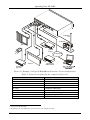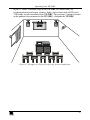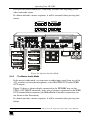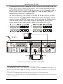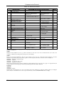
1
Kramer Electronics, Ltd.
USER MANUAL
Model:
VP-23RC
Presentation Switcher / Controller
Contents
Contents
1
2
2.1
3
3.1
Introduction
Getting Started
Quick Start
Overview
About the VP-23RC
1
1
1
3
3
3.1.1
3.1.2
3.1.3
Understanding the Presentation Switcher Section
Understanding the Media / Room Controller Section
Controlling the VP-23RC
3
4
5
3.2
3.3
3.4
4
4.1
4.2
4.3
5
6
6.1
6.2
6.3
7
7.1
Connecting the VP-23RC Rear Panel
Recommendations for Achieving the Best Performance
Terminology Used in this User Manual
Your Presentation Switcher / Controller
The VP-23RC Front Panel
The VP-23RC Rear Panel
The VP-23RC Underside Panel
Installing the VP-23RC on a Rack
Connecting the VP-23RC Presentation Switcher Section
Connecting the Balanced/Unbalanced Stereo Audio Input/Output
Wiring the CAT 5 LINE OUT RJ-45 Connector
Shielded Twisted Pair (STP) / Unshielded Twisted Pair (UTP)
Connecting to the Media / Room Controller Equipment
Setting the Media / Room Controller PROGRAM Dipswitches
6
7
7
8
8
10
13
14
15
17
18
18
19
21
7.1.1
Factory Reset
21
8
8.1
Controlling the VP-23RC
Controlling the VP-23RC via a PC
22
22
8.1.1
Connecting an RS-232 port to a PC
23
8.2
Controlling Additional Kramer Machines via RS-232 and RS-485
24
8.2.1
The Presentation Switcher Section Dipswitches
24
8.3
Controlling via the ETHERNET
25
8.3.1
8.3.2
8.3.3
Connecting the ETHERNET Port directly to a PC (Crossover Cable)
26
Configuring Your PC
26
Connecting the ETHERNET Port via a Network Hub (Straight-Through Cable) 27
9
9.1
9.2
9.3
Operating Your VP-23RC
The Front Panel Buttons
Configuration of the VP-23RC
Media / Room Controller Section Operation
28
28
29
29
9.3.1
9.3.2
9.3.3
Operating the Media / Room Controller
An Example of Operating the VP-23RC
Using the Media / Room Controller Macro Buttons
32
33
33
i
Contents
9.3.4
Turning the Light of the Backlit Buttons On and Off
34
9.4
The Presentation Switcher Section Operation
34
9.4.1
9.4.2
9.4.3
The Independent Switchers Mode
The Master Audio Mode
The Presentation Switcher SELECTOR Buttons Macro Sequence
34
35
37
10
10.1
Flash Memory Upgrade
Flash Memory Upgrade for the Presentation Switcher Section
38
38
10.1.1 Downloading from the Internet
10.1.2 Connecting the PC to the RS-232 Port
10.1.3 Upgrading the Firmware
38
38
39
10.2
Flash Memory Upgrade for the Media / Room Controller Section
43
10.2.1
10.2.2
10.2.3
10.2.4
Downloading from the Internet
Connecting the PC to the RS-232 Port
Upgrading Firmware
Installing the Web Applet
43
43
44
44
10.3
11
12
12.1
13
Troubleshooting Firmware Upgrade Issues
Technical Specifications
Hex Table
Audio Gain Control Hex Tables
Communication Protocol
45
46
47
47
49
Figures
Figure 1: VP-23RC Configuration Example
Figure 2: VP-23RC Presentation Switcher / Controller – Front View
Figure 3: VP-23RC Presentation Switcher / Controller – Rear View
Figure 4: VP-23RC Presentation Switcher / Controller – Underside View
Figure 5: Connecting the VP-23RC Presentation Switcher Section
Figure 6: Connecting the Balanced Stereo Audio Input/Output
Figure 7: Connecting the Unbalanced Stereo Audio Input
Figure 8: Connecting the Unbalanced Stereo Audio Output
Figure 9: CAT 5 PINOUT
Figure 10: Connecting the VP-23RC Media/Room Controller Section
Figure 11: Connecting a PC without using a Null-modem Adapter
Figure 12: Default Dipswitch Settings
Figure 13: Control Configuration via RS-232 and RS-485
Figure 14: Local Area Connection Properties Window
Figure 15: Internet Protocol (TCP/IP) Properties Window
Figure 16: Example of a Typical Media/Room Controller Section Configuration
Figure 17: Example of a Typical Setup in the Lecture Auditorium
Figure 18: Labels Setup
Figure 19: VP-23RC Operation Example
Figure 20: Separate Switcher Mode
Figure 21: Switching in the Master Audio Mode
Figure 22: Presentation Switcher Macro Sequence Example
Figure 23: Splash Screen
ii
6
9
11
13
16
17
17
17
18
20
23
24
25
26
27
30
31
32
33
35
36
37
39
KRAMER: SIMPLE CREATIVE TECHNOLOGY
Contents
Figure 24: Atmel – Flip Window
Figure 25: Device Selection Window
Figure 26: Selecting the Device from the Selection Window
Figure 27: Loading the Hex
Figure 28: RS-232 Window
Figure 29: Atmel – Flip Window (Connected)
Figure 30: Atmel – Flip Window (Operation Completed)
Figure 31: The KFR-Programmer Window
39
40
40
41
41
42
42
44
Tables
Table 1: Terminology Used in this User Manual
Table 2: Front Panel VP-23RC Presentation Switcher / Controller Features
Table 3: Rear Panel VP-23RC Presentation Switcher / Controller Features
Table 4: VP-23RC Underside Panel Features
Table 5: CAT 5 PINOUT
Table 6: PROGRAM Dipswitch Settings
Table 7: Connecting an RS-232 Port to a PC
Table 8: Dipswitch Settings
Table 9: Connection Scheme (for the example in Figure 16)
Table 10: The Commands Configuration
Table 11: Technical Specifications of the VP-23RC Presentation Switcher / Controller
Table 12: VP-23RC Hex Table
Table 13: VP-23RC Master Audio Selector Hex Table
Table 14: Set the Audio Output Gain Control for the Groups
Table 15: Set the Audio Output Gain Control for the Microphone
Table 16: Set the Audio Output Gain Control for the Master Audio
Table 17: Increase or Decrease the Audio Output Gain by One Step
Table 18: Protocol Definitions
Table 19: Instruction Codes
7
10
12
13
18
21
23
24
30
32
46
47
47
47
47
48
48
49
50
iii
Introduction
1
Introduction
Welcome to Kramer Electronics! Since 1981, Kramer Electronics has been
providing a world of unique, creative, and affordable solutions to the vast range
of problems that confront the video, audio, presentation, and broadcasting
professional on a daily basis. In recent years, we have redesigned and upgraded
most of our line, making the best even better! Our 1,000-plus different models
now appear in 11 groups1 that are clearly defined by function.
Congratulations on purchasing your Kramer VP-23RC Presentation Switcher
/ Controller, which is ideal for:
Controlling multimedia rooms, such as classrooms, auditoriums,
conference rooms and so on
Production studios, rental and staging
The package includes:
VP-23RC
Windows®-based Kramer control software and Kramer RC Configuration
software
Null-modem adapter, power cord2, and one 3.5mm to IR emitter control cable
Kramer RC-IR2 Infrared Remote Control Transmitter (including the
required batteries and a separate user manual3)
This user manual3
2
Getting Started
We recommend that you:
Unpack the equipment carefully and save the original box and packaging
materials for possible future shipment
Review the contents of this user manual
Use Kramer high performance high resolution cables4
2.1 Quick Start
This quick start chart summarizes the basic setup and operation:
1 GROUP 1: Distribution Amplifiers; GROUP 2: Switchers and Matrix Switchers; GROUP 3: Control Systems; GROUP 4:
Format/Standards Converters; GROUP 5: Range Extenders and Repeaters; GROUP 6: Specialty AV Products; GROUP 7:
Scan Converters and Scalers; GROUP 8: Cables and Connectors; GROUP 9: Room Connectivity; GROUP 10: Accessories
and Rack Adapters; GROUP 11: Sierra Products
2 We recommend that you use only the power cord that is supplied with this machine
3 Download up-to-date Kramer user manuals from our Web site at http://www.kramerelectronics.com
4 The complete list of Kramer cables is on our Web site at http://www.kramerelectronics.com
1
Getting Started
2
KRAMER: SIMPLE CREATIVE TECHNOLOGY
Overview
3
Overview
This section describes:
Using shielded twisted pair (STP)/unshielded twisted pair (UTP) (see
section 6.3)
The VP-23RC (see section 3.1)
Presentation Switcher section (see section 3.1.1)
Media / Room Controller (see section 3.1.2)
Means of control (see section 3.1.3)
An example of how to connect the VP-23RC (see section 3.2)
Recommendations for achieving the best performance (see section 3.3)
Terminology used in this user manual (see section 3.4)
3.1 About the VP-23RC
The VP-23RC is a high quality all-in-one Presentation Switcher and Media/Room
Controller, which lets you control A/V equipment and room items such as window
blinds, room lights, and a projector lift. The VP-23RC includes two major
sections: the Presentation Switcher section and the Media/Room Controller
section, each of which can be operated independently, or in tandem.
3.1.1
Understanding the Presentation Switcher Section
The Presentation Switcher section includes three independent 4x1 audio/video
switchers1, and a master audio switcher2.
The VP-23RC Presentation Switcher section features:
Three sets of four selector buttons (for composite video and audio, s-Video
and audio, and VGA/UXGA and audio), and four master audio selector
buttons (CV, s-Video, VGA/UXGA and Mic). Each of these 16 selector
buttons lets you select the inputs to switch to the outputs and can be
configured3 to carry out a sequence of up to 15 commands (a macro) so
that when pressing a configured button, the switching action is followed
by a macro sequence
VGA/UXGA video bandwidth of 350MHz to ensure transparent
performance even in the most critical applications, and is HDTV compatible
Composite/SDI video bandwidth of 650MHz, an s-Video bandwidth of
385MHz, and a CAT 5 bandwidth of 158MHz
1 A 4x1 switcher for composite video and audio, a 4x1 switcher for s-Video and audio, and a 4x1 switcher for computer
graphics (VGA/UXGA) signals with audio
2 That routes one of the pre-selected audio inputs (from these three switchers) to two separate outputs
3 By the system integrator
3
Overview
Digital microphone input level control and digital master audio level
control
Microphone talk-over mode1
A CAT 5 output, with a transmission range of more than 300 feet (over 100
meters) that transmits VGA/UXGA signals2 to a remote acceptor via a
receiver
An internal 5-Watt per channel (24kHz, 3dB) power amplifier for
connecting the speakers directly to the machine
A panel LOCK button to prevent tampering with the front panel
Recall of the previous setup from non-volatile memory
Audio output level change (via RS-232)
3.1.2
Understanding the Media / Room Controller Section
The Media/Room Controller section controls A/V equipment—especially
projectors and associated equipment3—in media rooms (such as classrooms,
boardrooms, or auditoriums), as well as room functions such as lights, blinds,
a projector lift and/or a screen motor.
The VP-23RC Media/Room Controller section includes:
Eight configurable buttons to set up any supported commands
An Ethernet port4 for configuration and control
Two bidirectional RS-2325 serial ports for universal display (for example,
projectors) and control of the VP-23RC (or other) switcher
Four relays for the simplified and centralized control of room functions
(such as lights, blinds, screen settings, and so on). The relays have
normally open (NO) and normally closed (NC) contacts
Three IR control ports
An IR-learner for the customized remote transmitters, without the need for
an external unit IR remote control
Macro mode operation, for programming up to 15 commands with the
press of a single button
Firmware upgrade support
1 The microphone input signal lowers the line audio output level when the connected microphone detects sound
2 Excludes audio
3 Including the A/V equipment connected to the VP-23RC Presentation Switcher section
4 Also for controlling the Presentation Switcher section
5 The RS-232 terminal block port (item 14 in Figure 3) is also used for firmware upgrade
4
KRAMER: SIMPLE CREATIVE TECHNOLOGY
Overview
3.1.3
Controlling the VP-23RC
Control the VP-23RC using the front panel buttons, or remotely via:
RS-2321 serial commands transmitted by a touch screen system, PC, or
other serial controller
The Kramer Infrared remote control transmitter
The ETHERNET2
The VP-23RC is dependable, rugged, and fits into two vertical spaces (2U) of
a standard 19” professional rack.
1 The RS-232 port (item 24 in Figure 3) located in the SWITCHER CONTROL area of the rear panel
2 The Ethernet port is located in the CONTROLLER area of the rear panel and is also used for configuration of the
media/room controller section by the system integrator
5
Overview
3.2 Connecting the VP-23RC Rear Panel
The VP-23RC can be connected in different configurations, integrating the
Presentation Switcher section with the Media/Room Controller section. The
block diagram in Figure 1 shows a VP-23RC configuration example:
Relays
IR Emitters
RS-232
Figure 1: VP-23RC Configuration Example
In this example:
Three VIDEO sources are connected to the inputs
The three VIDEO outputs are all connected to the same projector
The projector is connected to the RS-232 port in the CONTROLLER area
Two of the video sources are also connected to the IR terminal blocks
A CAT 5 UXGA receiver is connected
Various room items are connected to the RELAY terminal blocks
A microphone and speakers are connected, as well as the audio inputs and
outputs
6
KRAMER: SIMPLE CREATIVE TECHNOLOGY
Overview
To connect the VP-23RC as illustrated in the block diagram in Figure 1:
Connect the A/V equipment1 to the Presentation Switcher section (see
section 6)
Connect the A/V equipment and room items to the Media/Room
Controller section (see section 7)
3.3 Recommendations for Achieving the Best Performance
To achieve the best performance:
Connect only good quality connection cables, thus avoiding interference,
deterioration in signal quality due to poor matching, and elevated noiselevels (often associated with low quality cables)
Avoid interference from neighboring electrical appliances and position
your Kramer VP-23RC away from moisture, excessive sunlight and dust
3.4 Terminology Used in this User Manual
Table 1 defines some terms that are used in this user manual.
Table 1: Terminology Used in this User Manual
Term
Definition
The standard specification for ETHERNET that is maintained by the Institute of Electrical
and Electronics Engineers (IEEE).
Dynamic Host
Allows the network administrator to distribute IP addresses from a central point and
Configuration
automatically send a new IP address when an Ethernet point is plugged into a different
Protocol (DHCP)
network location
Gateway
A network position serving as an entry to another network. On the Internet, a node or
stopping point can be either a gateway node or a host (end-point) node.
IP Address
A 32-binary digit number that identifies each sender or receiver (within a network via a
particular server or workstation) of data (HTML pages or e-mails) that is sent in packets
across the Internet. Every device connected to an IP network must have a unique IP
address. This address is used to reference the specific unit.
Local Area Network Computers sharing a common communications line or wireless link, which often share a
(LAN)
server within a defined geographic area.
Media Access
A computer's unique hardware number (or address) in a LAN or other network. On an
Control (MAC)
Ethernet LAN, the (MAC) address is identical to the Ethernet address.
Address
Transmission
The basic communication language or protocol of the Internet that breaks the message
Control
into appropriately sized packets for the network, and can be used as a communications
Protocol/Internet
protocol in an intranet or an extranet.
Protocol (TCP/IP)
802.3
1 Such as DVD players, video players, speakers and so on
7
Your Presentation Switcher / Controller
4
Your Presentation Switcher / Controller
The VP-23RC front and rear panels relate in the following way:
The Presentation Switcher section relates to the AUDIO, VIDEO and
SWITCHER CONTROL areas on the rear panel
The Media/Room Controller section relates to the CONTROLLER area on
the rear panel
The Power connector, the RS-232 port in the SWITCHER CONTROL
AREA and the ETHERNET port are common to both sections
This section describes the VP-23RC:
Front panel (see section 4.1)
Rear panel (see section 4.2)
Underside panel (see section 4.3)
4.1 The VP-23RC Front Panel
Figure 2 and Table 2 define the front panel of the VP-23RC.
8
KRAMER: SIMPLE CREATIVE TECHNOLOGY
Your Presentation Switcher / Controller
Figure 2: VP-23RC Presentation Switcher / Controller – Front View
9
Your Presentation Switcher / Controller
Table 2: Front Panel VP-23RC Presentation Switcher / Controller Features
#
1
Feature
IR (Infrared) Receiver
2
3
4
POWER Switch
IR IN Receiver
MEDIA / ROOM CONTROLLER
Buttons
s-VIDEO (Y/C)-AUDIO SELECTOR
Buttons
VIDEO (CV)-AUDIO SELECTOR
Buttons
VGA/UXGA-AUDIO SELECTOR
Buttons
CV Button
5
6
7
8
9
10
11
12
13
14
Function
Signals from the Kramer remote control transmitter illuminate
the LED
Illuminated switch for turning the unit ON or OFF
1
Accepts IR remote commands for the IR learner feature
2
Control the room and the A/V equipment (from 1 to 8)
2
Selects the s-Video-audio source (from 1 to 4)
2
Selects the composite video-audio source (from 1 to 4)
Selects the VGA/UXGA video-audio source from (1 to 4)2
Press to route the selected audio signal from the composite
3
video section to the master audio outputs
s-VIDEO Button
Press to route the selected audio signal from the s-Video
3
MASTER
section to the master audio outputs
AUDIO
2
VGA/UXGA
Button
Press
to
route
the
selected
audio
signal
from the
SELECTOR
3
VGA/UXGA section to the master audio outputs
MIC Button
Press to route the microphone input to the master audio
outputs3
- Button Decrease the microphone audio signal level
MIC
+ Button Increase the microphone audio signal level
AUDIO LEVEL
+ Button Increase the master audio signal level
MASTER
- Button Decrease the master audio signal level
LOCK Button
Press to lock the front panel buttons
TALK OVER Button
Push the button to activate talk over4
4.2 The VP-23RC Rear Panel
Figure 3 and Table 3 define the rear panel of the VP-23RC.
1 Used by the system integrator only, see section 9.2
2 Each button when pressed can also execute a macro sequence of up to 15 programmed commands (as configured by the
system integrator)
3 MASTER OUT and SPKR OUT
4 With the TALK OVER button selected, speaking into the microphone amplifies the voice of the speaker, overriding and
fading out all other audio channels. However, pressing the MIC button in the Master Audio Selector renders the Talk Over
function inactive
10
KRAMER: SIMPLE CREATIVE TECHNOLOGY
Your Presentation Switcher / Controller
Figure 3: VP-23RC Presentation Switcher / Controller – Rear View
11
Your Presentation Switcher / Controller
Table 3: Rear Panel VP-23RC Presentation Switcher / Controller Features
Feature
MIC IN Connector
COND. / DYN Selector Switch
3
4
5
6
7
CV OUT Terminal Block Connector
Y/C OUT Terminal Block Connector
UXGA OUT Terminal Block Connector
MASTER OUT Terminal Block Connector
CV IN Terminal Block Connectors
AUDIO
#
1
2
17
18
19
20
21
22
23
24
25
26
27
28
VIDEO
15
16
SWITCHER CONTROL
12
13
14
Y/C IN Terminal Block Connectors
UXGA IN Terminal Block Connectors
SPKR OUT Terminal Block Connector
RELAY Terminal Block Connector
CONTROLLER
8
9
10
11
Function
Connect to the microphone
Push in to select a condenser, release to select a
dynamic microphone
Connect to the composite video balanced audio acceptor
Connect to the s-Video balanced audio acceptor
Connect to the VGA/UXGA balanced audio acceptor
Connect the master balanced audio channel acceptor1
2
Connect to the composite video balanced audio sources
2
Connect to the s-Video balanced audio sources
2
Connect to the VGA/UXGA balanced audio sources
Connect to a pair of loudspeakers
2
Connect each relay to a room item. The PINOUT is:
NO: Normally Open; C: Common; NC: Normally
Closed
Connect to an IR emitter cable (from IR1 to IR 3)
Connects to the PC through computer networking3
Connect to the RS-232 port of the A/V equipment or a
PC or other Serial Controller
IR Terminal Block Connectors
ETHERNET Connector
RS-232 Port 1:Terminal Block
4
Ports
Connector (G, Rx, Tx)
Port 2: 9-pin D-sub Connector
PROGRAM Dipswitches
DIP1 is for firmware upgrade (see section 10.2); DIP 3
is for factory reset; DIP 2 and DIP 4 are not used (see
section 7.1)
CV IN BNC Connectors
Connect to the composite video sources2
CV OUT BNC Connector
Connect to the composite video acceptor
Y/C IN 4-pin Connectors
Connect to the s-Video sources2
Y/C OUT 4-pin Connector
Connect to the s-Video acceptor
UXGA IN 15-pin HD Connectors
Connect to the VGA/UXGA video sources2
UXGA OUT 15-pin HD Connector
Connect to the VGA/UXGA video acceptor
UXGA CAT5 OUT
Connect to a remote computer graphics acceptor via
a receiver (for example, the TP-120), see section 3.2
RJ-45 Connector
Connect to a PC to control the VP-23RC
RS-232 9-pin D-sub Port
FLASH PROG. Button
RS-485 Terminal Block Port
Dipswitches
Power Connector with Fuse
Push in to upgrade the Presentation Switcher section to
the latest Kramer firmware (see section 10.1), or
release for Normal (the factory default)
Pins B (-) and A (+) are for RS-485; Pin G may be
connected to the shield (if required)
DIPs 1, 2 and 3 are OFF, DIP 4 is ON for RS-485
termination
AC connector enabling power supply to the unit
1 Both the MASTER OUT and the SPKR OUT terminal block connectors receive the same signal: the MASTER OUT
outputs the signal as it is while the SPKR OUT is amplified
2 From 1 to 4
3 To configure the Media/Room Controller section or control the VP-23RC via the ETHERNET
4 Port 1 can connect to a PC to upgrade the firmware of the Media/Room Controller section
12
KRAMER: SIMPLE CREATIVE TECHNOLOGY
Your Presentation Switcher / Controller
4.3 The VP-23RC Underside Panel
Figure 4 and Table 4 define the VP-23RC underside features:
RESET
VS
HS
Figure 4: VP-23RC Presentation Switcher / Controller – Underside View
Table 4: VP-23RC Underside Panel Features
Feature
RESET Button
VS Switch
HS Switch
Function
Press to reset the unit prior to firmware upgrade (see section 10.1)
Slide the switch to the left (to NORMAL) to retain the polarity of the
vertical sync pulses on the UXGA CAT5 OUT connector; slide the switch
to the right1 to change the vertical sync pulses on the UXGA CAT5 OUT
connector (VS) polarity to NEGATIVE polarity2
Slide the switch to the left (to NORMAL) to retain the polarity of the
horizontal sync pulses on the UXGA CAT5 OUT connector; slide the
switch to the right1 to change the horizontal sync pulses on the UXGA
CAT5 OUT connector (HS) polarity to NEGATIVE polarity2
1 By default, both switches are set to the left
2 Downgoing syncs
13
Installing the VP-23RC on a Rack
5
Installing the VP-23RC on a Rack
This section describes what to do before installing on a rack and how to rack
mount.
Before Installing on a Rack
Before installing on a rack, be sure that the environment is
within the recommended range:
Operating temperature range +5° to +45° C (41° to 113° F)
Operating humidity range
10 to 90% RHL, non-condensing
Storage temperature range
-20° to +70° C (-4° to 158° F)
Storage humidity range
5 to 95% RHL, non-condensing
How to Rack Mount
To rack-mount a machine:
1. Attach both ear brackets to the
machine. To do so, remove the
screws from each side of the
machine (3 on each side), and
replace those screws through the
ear brackets.
CAUTION!!
When installing on a 19" rack, avoid hazards by taking
care that:
1. It is located within the recommended environmental
conditions, as the operating ambient temperature of a
closed or multi unit rack assembly may exceed the
room ambient temperature.
2. Once rack mounted, enough air will still flow around
the machine.
3. The machine is placed straight in the correct
horizontal position.
4. You do not overload the circuit(s). When connecting
the machine to the supply circuit, overloading the
circuits might have a detrimental effect on overcurrent
protection and supply wiring. Refer to the appropriate
nameplate ratings for information. For example, for
fuse replacement, see the value printed on the
product label.
5. The machine is earthed (grounded) in a reliable way
and is connected only to an electricity socket with
grounding. Pay particular attention to situations where
electricity is supplied indirectly (when the power cord
is not plugged directly into the socket in the wall), for
example, when using an extension cable or a power
strip, and that you use only the power cord that is
supplied with the machine.
14
2. Place the ears of the machine
against the rack rails, and insert the
proper screws (not provided)
through each of the four holes in the
rack ears.
Note that:
In some models, the front panel
may feature built-in rack ears
Detachable rack ears can be
removed for desktop use
Always mount the machine in the
rack before you attach any cables
or connect the machine to the
power
If you are using a Kramer rack
adapter kit (for a machine that is not
19"), see the Rack Adapters user
manual for installation instructions
(you can download it at:
http://www.kramerelectronics.com)
KRAMER: SIMPLE CREATIVE TECHNOLOGY
Connecting the VP-23RC Presentation Switcher Section
6
Connecting the VP-23RC Presentation Switcher Section
To connect1 the VP-23RC Presentation Switcher section, as illustrated in the
example in Figure 5, do the following2:
1. Connect the following video sources:
One3 composite video source (for example, a composite video player)
to the CV IN 1 BNC connector
One3 s-Video source (for example, an s-Video player) to the Y/C IN 1
4-pin connector
One3 VGA/UXGA source (for example, a computer graphics source)
to the UXGA IN 1 15-pin HD connector
2. Connect the acceptors to a projector4 as follows:
The composite video CV OUT BNC connector to the composite video
input of the projector
The s-Video Y/C OUT 4-pin connector to the s-Video input of the
projector
The VGA/UXGA UXGA OUT 15-pin HD connector to the
VGA/UXGA input of the projector
3. Connect the appropriate balanced5 audio sources and acceptors (not shown in
Figure 5).
4. If required, connect the MASTER OUT terminal block connector (not shown
in Figure 5; see section 9.4.2).
5. Connect the SPKR OUT block connector to a pair of loudspeakers, by
connecting the left loudspeaker to the “L+” and the “L-” terminal block
connectors, and the right loudspeaker to the “R+” and the “R-” terminal block
connectors. Do not Ground the loudspeakers.
6. Connect the UXGA CAT5 OUT twisted pair connector (see section 6.2) to a
line receiver (for example, the TP-120 XGA Line Receiver6, which is
connected to a remote display).
7. If required, connect a dynamic or a condenser microphone7 to the MIC IN XLR
connector.
1 You do not need to connect all the inputs
2 Switch OFF the power on each device before connecting it to your VP-23RC. After connecting your VP-23RC, switch on
its power and then switch on the power on each device
3 Although in this example only one source is connected, you can connect all of the four inputs, that is, 12 in total
4 In this example a projector is used, but you can also connect separate outputs such as displays or video recorders
5 To connect audio inputs and outputs, see section 6.1
6 The receiver receives the CAT 5 signal, decodes it and outputs it to a VGA acceptor
7 Use the Con / Dyn switch (refer to the rear panel, item 2 in Figure 3) to select a dynamic microphone or a condenser
15
Connecting the VP-23RC Presentation Switcher Section
8. If required, connect a PC to the RS-232 port (see section 8.1.1).
Figure 5: Connecting the VP-23RC Presentation Switcher Section
16
KRAMER: SIMPLE CREATIVE TECHNOLOGY
Connecting the VP-23RC Presentation Switcher Section
6.1 Connecting the Balanced/Unbalanced Stereo Audio Input/Output
Figure 6 illustrates how to wire a balanced input/output connection:
Figure 6: Connecting the Balanced Stereo Audio Input/Output
Figure 7 illustrates how to wire an unbalanced input:
Figure 7: Connecting the Unbalanced Stereo Audio Input
Figure 8 illustrates how to wire an unbalanced acceptor to the balanced output
of the unit:
Figure 8: Connecting the Unbalanced Stereo Audio Output
17
Connecting the VP-23RC Presentation Switcher Section
6.2 Wiring the CAT 5 LINE OUT RJ-45 Connector
Table 5 and Figure 9 define the CAT 5 PINOUT, using a straight pin-to-pin
cable with RJ-45 connectors:
Table 5: CAT 5 PINOUT
EIA /TIA 568A
PIN
1
2
3
4
5
6
7
8
Wire Color
Green / White
Green
Orange / White
Blue
Blue / White
Orange
Brown / White
Brown
Figure 9: CAT 5 PINOUT
EIA /TIA 568B
PIN
1
2
3
4
5
6
7
8
Wire Color
Orange / White
Orange
Green / White
Blue
Blue / White
Green
Brown / White
Brown
Pair 1
4 and 5
Pair 1
Pair 2
3 and 6
Pair 2
4 and 5
1 and 2
Pair 3
1 and 2
Pair 3
3 and 6
Pair 4
7 and 8
Pair 4
7 and 8
6.3 Shielded Twisted Pair (STP) / Unshielded Twisted Pair (UTP)
We recommend that you use shielded twisted pair (STP) cable. There are
different levels of STP cable available, and we advise you to use the best
quality STP cable that you can afford. Our non-skew-free cable, Kramer
BC-STP, which is intended for digital signals and for analog signals where
skewing is not an issue, is recommended for the VP-23RC. For cases where
there is skewing, our UTP skew-free cable, Kramer BC-XTP, may be used.
Bear in mind, though, that we advise using STP cables where possible, since
the compliance to electromagnetic interference was tested using those cables.
Although unshielded twisted pair (UTP) cable might be preferred for long
range applications, the UTP cable should be installed far away from electric
cables, motors and so on, which are prone to create electrical interference. However,
since the use of UTP cable might cause inconformity to electromagnetic standards,
Kramer does not commit to meeting the standard with UTP cable.
You can connect to a remote computer graphics acceptor via a receiver (for
example, the TP-120), see section 3.2.
Some Kramer twisted pair products include the Power Connect feature. The
VP-23RC does not have this feature.
18
KRAMER: SIMPLE CREATIVE TECHNOLOGY
Connecting to the Media / Room Controller Equipment
7
Connecting to the Media / Room Controller Equipment
To connect1 the VP-23RC Media/Room Controller section, as the example
illustrated in Figure 10 shows, do the following2:
1. Connect the RELAY3 terminal block connectors as follows:
Connect RELAY 1 to the blinds
Connect RELAY 2 to the lighting system
Connect RELAY 3 to the projector lift
Connect RELAY 4 to the screen
2. Connect the IR terminal block connectors4, via the Kramer IR Emitter Control
Cable (C-A35/IRE-10)5, as follows:
Connect IR 1 to the composite video player (connected
to CV IN 1 on the VP-23RC)
Connect IR 2 to the s-Video player (connected to Y/C
IN 1 on the VP-23RC)
3. Connect the RS-232 port 1 to the projector6.
4. Set the PROGRAM dipswitches (see section 7.1).
5. Connect the power cord.
Upon completion of the installation, and before operation, the VP-23RC needs
to be configured by the system integrator (see section 9.2)
1 You do not need to connect all the items
2 Note that Figure 10 emphasizes the connections related to the Media/Room Controller section, other connections are grayed
out
3 On each 3-pole terminal block connector, connect either: C to NO, or C to NC (C is Common, NO is Normally Open and
NC is Normally Closed)
4 VP-23RC has three IR emitters. In this example only two IR emitters are connected
5 Refer to the cables’ user manuals for installation instructions. In addition, two IR Emitter Extension Cables are also
available: a 15 meter cable and a 20 meter cable
6 In this example only Port 1 is connected, but you can also connect the RS-232 port 2 to a display or other device (or, if
required, connect it to a PC for firmware upgrade, see section 10.2)
19
Connecting to the Media / Room Controller Equipment
s-Video
Player
Screen
Blinds
Composite
Video
Player
Computer
Graphics Source
Projector
Projector
Lift
Lighting
System
Figure 10: Connecting the VP-23RC Media/Room Controller Section
20
KRAMER: SIMPLE CREATIVE TECHNOLOGY
Connecting to the Media / Room Controller Equipment
7.1 Setting the Media / Room Controller PROGRAM Dipswitches
The PROGRAM dipswitches are located in the CONTROLLER area of the
rear panel (see section 7.1). Table 6 defines the PROGRAM dipswitch
settings:
Table 6: PROGRAM Dipswitch Settings
DIPS
7.1.1
1
Description
ON for Firmware Upgrade (see section 10.2)
2
Not used
3
ON for Factory Reset (see section 7.1.1)
4
Not used
Factory Reset
Factory reset clears all the button macro configurations1, serial ports definition and
also returns the IP number, Gateway and Net mask to their preset default settings2.
Warning: Factory Reset erases all the configured button macros
To reset the Media/Room Controller to its default settings, do the following:
1. Turn the power on the VP-23RC OFF.
2. Set DIP 3 ON.
3. Turn the power on the VP-23RC ON.
The machine initializes after about 5 seconds
4. Set DIP 3 OFF.
1 On the Media/Room Controller buttons as well as on the Presentation Switcher SELECTOR buttons
2 IP number: 192.168.1.39, Gateway: 0.0.0.0, and Net mask: 255.255.0.0
21
Controlling the VP-23RC
8
Controlling the VP-23RC
The VP-23RC can be controlled via:
A PC (see section 8.1)
RS-232 and RS-485 (see section 8.2)
The ETHERNET (see section 8.3)
8.1 Controlling the VP-23RC via a PC
To control the VP-23RC1 via the control software:
1. Connect your PC to the SWITCHER CONTROL RS-232 port on the rear
panel (see section 8.1.1).
2. Download the Windows®-based Kramer control software (provided with the
machine) to your PC.
3. Run the application. The Port window appears.
4. Select the Local Connection area, select the COM port2 to which the
VP-23RC is connected, and click OK.
The application finds the unit automatically.
1 The Media/Room Controller section can be controlled by a PC only if the MEDIA / ROOM CONTROLLER buttons are
configured (see section 9.2)
2 If you want to use the Windows®-based Kramer control software via the Ethernet, select the Remote Connection area,
insert the machine’s IP number and set the port to 5002
22
KRAMER: SIMPLE CREATIVE TECHNOLOGY
Controlling the VP-23RC
8.1.1
Connecting an RS-232 port to a PC
You can connect a PC to the VP-23RC via an RS-232 port, as defined in Table 7:
Table 7: Connecting an RS-232 Port to a PC
RS-232 Rear Panel Port Location
Port 1 in the CONTROLLER area
RS-232 port in the SWITCHER
CONTROL area
For…
Media/Room Controller firmware upgrade (see section 10.2)
Presentation Switcher firmware upgrade (see section 10.1)
Controlling the VP-23RC via a PC (see section 8)
Controlling other Kramer machines that are connected to
the VP-23RC via RS-485 (see section 8.2)
To connect a PC using the Null-modem adapter provided with the machine
(recommended method):
Connect the RS-232 9-pin D-sub rear panel port1 on the VP-23RC to the
Null-modem adapter2 via a 9-wire flat cable and connect the Null-modem
adapter to the RS-232 9-pin D-sub port on your PC
To connect without using a Null-modem adapter:
Connect the RS-232 9-pin D-sub port on your PC to the RS-232 9-pin
D-sub rear panel port on the VP-23RC, as Figure 11 illustrates
PIN 5 Connected to PIN 5 (Ground)
PIN 3 Connected to PIN 2
PIN 2 Connected to PIN 3
Female DB9 (From PC)
Male DB9
PIN 4 Connected to PIN 6
PINS 8, 7, 1 Connected together
If a Shielded cable is used, connect the shield to PIN 5
Figure 11: Connecting a PC without using a Null-modem Adapter
1 Select the RS-232 port according to your needs, as defined in Table 7
2 For the male RS-232 port (port 2 in the CONTROLLER area), use a male-to-female adapter
23
Controlling the VP-23RC
8.2 Controlling Additional Kramer Machines via RS-232 and RS-485
You can cascade other Kramer machines1 together with the VP-23RC via the
RS-485 port, and control them via the SWITCHER CONTROL RS-232 port
using a PC.
To connect two Kramer VP-8x8A machines to the VP-23RC, via RS-485, as
illustrated in the example in Figure 13, do the following:
1. Connect the audio/video sources and acceptors on the VP-23RC and on the
additional Kramer machines (refer to the relevant user manuals for
installation instructions).
2. Connect the RS-232 port on the VP-23RC unit to the PC using the
Null-modem adapter provided with the machine (recommended), as section
8.1.1 describes.
3. Connect the RS-485 terminal block port on the VP-23RC to the RS-485 port
on the first VP-8x8A. Connect the RS-485 port on the first VP-8x8A to the
RS-485 port on the second VP-8x8A machine.
4. Set the dipswitches as follows:
Set the Machine number of each of the other units to a
machine number other than machine number 1
Set Dip 4 ON on the VP-23RC (RS-485 TERM) and
terminate the RS-485 line on the last unit
8.2.1
The Presentation Switcher Section Dipswitches
The Switcher setup dipswitches are located in the SWITCHER CONTROL
area of the rear panel. Table 8 and Figure 12 define the factory default
dipswitch settings2:
Table 8: Dipswitch Settings
DIPS
1, 2, 3
Function
Not used
Set to OFF
Description
4
RS-485
TERM
ON for RS-485 Line Termination with 120 ;
OFF for no RS-485 Line Termination
OFF
ON
1 2 3 4
Figure 12: Default
Dipswitch Settings
1 But not other VP-23RC machines
2 By default, all dipswitches are set to OFF
24
KRAMER: SIMPLE CREATIVE TECHNOLOGY
Controlling the VP-23RC
VP-23RC
Machine # 2
Machine # 3
VP-8x8A
VP-8x8A
Figure 13: Control Configuration via RS-232 and RS-485
8.3 Controlling via the ETHERNET
You can control the VP-23RC via the Ethernet as well as configure the
Media/Room Controller buttons and the Presentation Switcher SELECTOR
buttons1.
1 Done by the system integrator, see section 9.2
25
Controlling the VP-23RC
Before using the VP-23RC via a network hub or network router, make sure that:
The IP number of the machine is defined on the network subnet and that
its number is unique in the local network
A Firewall is not preventing access to the device
If you need further assistance, contact your system integrator.
8.3.1
Connecting the ETHERNET Port directly to a PC (Crossover Cable)
You can connect the Ethernet port of the VP-23RC to the Ethernet port on your
PC, via a crossover cable with RJ-45 connectors.
This type of connection is recommended for identification of the factory default
IP Address of the VP-23RC and for the initial configuration (see section 9.2)
8.3.2
Configuring Your PC
After connecting the Ethernet port, configure your PC as follows:
1. Right-click the My Network Places icon on your desktop.
2. Select Properties.
3. Right-click Local Area Connection Properties.
4. Select Properties.
The Local Area Connection Properties window appears.
5. Select the Internet Protocol (TCP/IP) and click the Properties Button (see
Figure 14).
Figure 14: Local Area Connection Properties Window
26
KRAMER: SIMPLE CREATIVE TECHNOLOGY
Controlling the VP-23RC
6. Select Use the following IP Address, and fill in the details as shown in
Figure 15.
7. Click OK.
Figure 15: Internet Protocol (TCP/IP) Properties Window
Remember to restore your previous PC settings after setting the VP-23RC IP
If the Media/Room Controller is not yet configured you can control via the
Ethernet, the Presentation Switcher section only.
8.3.3
Connecting the ETHERNET Port via a Network Hub (Straight-Through
Cable)
After initially configuring the ETHERNET port, you can connect the Ethernet
port of the VP-23RC to the Ethernet port on a network hub or network router,
via a straight-through cable with RJ-45 connectors.
27
Operating Your VP-23RC
9
Operating Your VP-23RC
This section describes the:
Front panel buttons (see section 9.1)
VP-23RC button configuration (see section 9.2)
Media/Room Control section operation (see section 9.3)
Presentation Switcher section operation (see section 9.4)
9.1 The Front Panel Buttons
The front panel buttons include the:
MEDIA / ROOM CONTROL buttons1 (1 to 8)
VIDEO (CV)-AUDIO SELECTOR buttons1 (1 to 4)
1
S-VIDEO (Y/C)-AUDIO SELECTOR buttons (1 to 4)
VGA/UXGA-AUDIO SELECTOR buttons1 (1 to 4)
MASTER AUDIO SELECTOR buttons1 (CV, S-VIDEO, VGA/UXGA
and MIC)
TALK OVER button2, which lowers or mutes the MASTER AUDIO
LEVEL when the microphone picks up speech3
MIC AUDIO LEVEL up and down buttons to adjust the level at the
master audio out4 connectors5 and the talk-over function threshold6
MASTER AUDIO LEVEL up and down buttons to adjust the audio
output level at the master audio out connectors4, without influencing any
other audio output
Panel LOCK button to lock the front panel buttons
7
By default , the stereo audio signals switch together with the video, that is, the
8
unit is set in audio-follow-video (AFV) mode. You can change to breakaway
9
mode , via the RS-232 port in the SWITCHER CONTROL area
1 Which can be programmed to execute a sequence of up to 15 commands per button (see section 9.4.3)
2 Two channels are active in the Talk Over mode, a source selected via the MASTER AUDIO SELECTOR buttons and the
microphone channel
3 Adjust the microphone level via the MIC AUDIO LEVEL + and - buttons
4 MASTER OUT and SPKR OUT
5 Useful in the TALK OVER mode, when the microphone level needs to be adjusted separately
6 Achieving optimum results for a particular environment when using a microphone may require experimentation in adjusting
the AUDIO and MIC LEVELS
7 This is, the pre-installed factory default. The default can be modified via the Windows®-based Kramer control software
8 In which all operations relate to both the video and the audio channels
9 In which video and audio channels switch independently
28
KRAMER: SIMPLE CREATIVE TECHNOLOGY
Operating Your VP-23RC
Pressing an illuminated AUDIO SELECTOR button for more than 2 seconds
disconnects that master audio output, and the button no longer illuminates.
The video will continue to display but without sound.
The Master Audio automatically follows the last input selected (for example,
VGA/UXGA), regardless of the switcher group (VGA, s-Video, or composite
video), and the respective button1 under the MASTER AUDIO SELECTOR
section illuminates, indicating that the selected input (for example,
VGA/UXGA) is routed to the master outputs.
9.2 Configuration of the VP-23RC
The Media/Room Controller section and the Presentation Switcher SELECTOR
buttons are configured by the system integrator. For further details, refer to the
Kramer RC configuration and Installation Guide PDF file, located in the
technical support section on our Web site: http://www.kramerelectronics.com
9.3 Media / Room Controller Section Operation
The Media/Room Controller section is easy-to-use, as the example in Figure
16 and Table 9 describes2:
1 Replacing the previous illuminated button
2 This example describes how to setup one of an unlimited number of available setups for the system
29
Operating Your VP-23RC
Projector
Lift
Projector
Blinds
s-Video
Player
INTERNET
Screen
Lighting
System
Composite
Video Player
Figure 16: Example of a Typical Media/Room Controller Section Configuration
Table 9: Connection Scheme (for the example in Figure 16)
This connector:
RELAY 1
RELAY 2
RELAY 3
RELAY 4
1
IR 1 PIN
IR 2 PIN1
IR 3 PIN
RS-232 Terminal Block Connector (1 and 2)
Ethernet
Controls:
The blinds
The lighting system
Projector lift motor
The screen settings motor
A composite video player
An s-Video player
Not connected in this example
(1) A projector; (2) an LCD2
The VP-23RC via a remote control PC
1 Connected via the IR emitter
2 Alternatively, the second RS-232 port can be used to control another A/V unit
30
KRAMER: SIMPLE CREATIVE TECHNOLOGY
Operating Your VP-23RC
Figure 17 shows a common setup for the VP-23RC in a media room. An
overhead projector and screen, speakers, lights; and a cabinet with a DVD and a
VCR inside, are all controlled via the VP-23RC. The presenter’s laptop is located
on the podium (also connected to the VP-23RC), alongside the VP-23RC.
VCR
DVD
Figure 17: Example of a Typical Setup in the Lecture Auditorium
31
Operating Your VP-23RC
9.3.1
Operating the Media / Room Controller
In the following example1, illustrated in Figure 18, the VP-23RC is labeled2
with specific functions and each button is programmed3 to perform several
tasks4 as defined in Table 10.
Each button may be assigned with up to 15 commands.
Table 10: The Commands Configuration
Button
1
ON
OFF
DVD
PC
VCR
Help
Vol
UP
Vol
DOWN
Figure 18: Labels Setup
The Macro Sequence
Power up the projector
Power up the DVD player
Power up the video player
Roll down the projector screen
Lower down the projector
from the ceiling
1 minute delay [for the
projector to heat up]
Turn lights off
Close blinds
30 second delay for blinds to close
The projector selects the PC input
2
Open blinds
Turn lights on
30 second delay for blinds to open
Power down the projector
Lift the projector up to the ceiling
Stop the DVD player
Power down the DVD player
Stop the video player
Power down the video player
Roll up the projector screen
3
Stop the video player
The projector selects the DVD input
Play the DVD
4
Audio level up
5
Stop the DVD
Stop the VCR
The projector selects a PC input
6
Stop the DVD
The projector selects the VCR input
Play the VCR
7
Signals for technical assistance
8
Audio level down
1 This is only one example among numerous possibilities, each button can be configured as required
2 To insert labels, refer to the Kramer RC configuration and Installation Guide PDF file, located in the technical support
section on our Web site: http://www.kramerelectronics.com
3 By the system integrator
4 A macro sequence, including up to 15 commands per button, carried out one after the other
32
KRAMER: SIMPLE CREATIVE TECHNOLOGY
Operating Your VP-23RC
9.3.2
An Example of Operating the VP-23RC
Figure 19 shows an operating example:
VCR
DVD
ON
DVD
Vol
UP
Vol
DOWN
PC
VCR
PC
OFF
Figure 19: VP-23RC Operation Example
9.3.3
Using the Media / Room Controller Macro Buttons
Pressing any button initiates a macro sequence1, during which the button
blinks (as programmed by the system integrator).
If during the macro sequence the button blinks faster than usual2, this indicates
that a malfunction has been detected3 and if the problem is critical, the VP-23RC
exits the macro sequence4.
5
To solve the problem, summon technical help
1 The macro sequence can be carried out instantly or can take a while, depending on the delay times included in the sequence
2 Six times per second, as compared with twice per second during normal operation
3 For example, a faulty DVD player
4 This procedure and others are set by the system integrator
5 In this example, press the HELP DESK button
33
Operating Your VP-23RC
If you want to stop a macro sequence, press and hold that button for 5
seconds. The sequence will come to an end. You can resume operation by
pressing any button1. The unit will carry out the macro sequence commands
from the beginning.
9.3.4
Turning the Light of the Backlit Buttons On and Off
When the room is darkened, the buttons can be illuminated for convenience.
To turn on the backlight, press buttons 3 and 7 simultaneously
To turn off the backlight, press the respective buttons once again.
9.4 The Presentation Switcher Section Operation
The Presentation Switcher section has two operation modes:
The Independent Switchers mode (see section 9.4.1)
The Master Audio mode (see section 9.4.2)
In both operation modes, if configured, the SELECTOR buttons, once
pressed, execute a sequence of configured commands (see section 9.4.3).
9.4.1
The Independent Switchers Mode
In the independent switchers mode, the three switchers of the VP-23RC operate
independently from each other, as illustrated in Figure 20 (the Media/Room
Controller connections are not shown in this illustration). You can route one of
the 4 CV inputs, one of the 4 Y/C inputs and one of the 4 VGA/UXGA inputs to
the corresponding CV, Y/C and UXGA2 outputs, respectively.
To switch an input to an output3:
Press one4 button from the set of four buttons in the VIDEO
(CV)-AUDIO SELECTOR section and/or5
One button from the set of four buttons in the s-VIDEO (Y/C)-AUDIO
SELECTOR section and/or5
One button from the set of four buttons in the VGA/UXGA-Audio
SELECTOR section
1 Including the button you kept pressed to stop the macro sequence
2 And to the UXGA CAT5 OUT connector (audio excluded)
3 Assuming that all inputs are connected
4 You cannot select more than one button in a section
5 You can overlook a section and choose not to select a button from it
34
KRAMER: SIMPLE CREATIVE TECHNOLOGY
Operating Your VP-23RC
Each pressed button illuminates1, indicating selection and outputting of that
video and audio source.
If a button includes a macro sequence, it will be executed when pressing that
button.
UXGA Acceptor
UXGA Sources
CV Video Sources
s-Video Sources
CV Video Acceptor
s-Video Acceptor
Speakers
Figure 20: Separate Switcher Mode
9.4.2
The Master Audio Mode
In the master audio mode, you can route an audio input signal from any of the
A/V switchers or from the microphone, to the MASTER OUT and/or SPKR
OUT outputs.
Figure 21 shows a plasma-display connected to the VP-23RC unit via the
UXGA OUT HD15F connector, and a pair of speakers connected to the SPKR
OUT terminal block connector (the Media/Room Controller connections are
not shown in this illustration).
If a button includes a macro sequence, it will be executed when pressing that
button.
1 Pressing an illuminated button for more than 2 seconds will disconnect the output and the button will no longer illuminate
35
Operating Your VP-23RC
(I) When pressing button 2 under the VGA/UXGA-AUDIO SELECTOR, the
UXGA IN 2 signal is routed to the display1. The VGA/UXGA button under
the MASTER AUDIO SELECTOR section automatically illuminates, and the
UXGA audio signal is routed to the SPKR OUT2 and the MASTER OUT2
terminal block connectors simultaneously3.
(II) After connecting a microphone to the MIC IN XLR connector, the MIC
button under the MASTER AUDIO SELECTOR section illuminates and the
speakers output the MIC IN4 audio signal, while retaining the UXGA display.
You can return to the UXGA audio output by pressing the VGA/UXGA
button under the MASTER AUDIO SELECTOR section once again.
I
II
I
II
Presenter’s
Microphone
UXGA Source
Speaker
Speaker
Display
Figure 21: Switching in the Master Audio Mode
1 The UXGA output is simultaneously routed to the UXGA CAT 5 OUT connector
2 The MASTER audio signal is routed simultaneously to the SPKR OUT and the MASTER OUT channels. The only
difference between them is that the SPKR OUT channel has an internal power amplifier, which lets you connect the speakers
directly to the unit
3 As well as to the AUDIO UXGA OUT terminal block connector, which is not connected in this example
4 Another way to use the microphone is to press the TALK OVER button: the main audio level is lowered when the
microphone picks up speech
36
KRAMER: SIMPLE CREATIVE TECHNOLOGY
Operating Your VP-23RC
9.4.3
The Presentation Switcher SELECTOR Buttons Macro Sequence
The SELECTOR buttons can be configured to execute a sequence of
commands (a macro) in a similar way to the Media / Room Controller buttons
(see section 9.3.1) so that when a SELECTOR button is pressed, it will first
perform the switching action and concurrently carry out the macro. The
example in Figure 22 illustrates a macro sequence that can be programmed to
a Presentation Switcher SELECTOR button.
Figure 22: Presentation Switcher Macro Sequence Example
Note that you cannot stop a macro on the presentation switcher SELECTOR
buttons once it is in process
37
Flash Memory Upgrade
10 Flash Memory Upgrade
The firmware is upgraded separately for the Presentation Switcher section (see
section 10.1) and for the Media/Room Controller section (see section 10.2).
10.1
Flash Memory Upgrade for the Presentation Switcher Section
The VP-23RC firmware for the Presentation Switcher section is located in
FLASH memory, which lets you upgrade to the latest Kramer firmware
version in minutes! The process involves:
Downloading from the Internet (see section 10.1.1)
Connecting the PC to the RS-232 port (see section 10.1.2)
Upgrading Firmware (see section 10.1.3)
10.1.1
Downloading from the Internet
You can download the up-to-date file1 from the Internet. To do so:
1. Go to our Web site at http://www.kramerelectronics.com and download the
file: “ FLIP_VP23RC.zip” from the Technical Support section.
2. Extract the file: “ FLIP_VP23RC.zip” to a folder (for example, C:\Program
Files\Kramer Flash).
3. Create a shortcut on your desktop to the file: “ FLIP.EXE”.
10.1.2
Connecting the PC to the RS-232 Port
Before installing the latest Kramer firmware version on a VP-23RC unit, do
the following:
1. Connect the RS-232 DB9 rear panel port in the SWITCHER CONTROL area
to the Null-modem adapter via a 9-wire flat cable, and connect the Nullmodem adapter to the RS-232 DB9 port on your PC (as in section 8.1.1).
2. On the rear panel, push in the FLASH PROG. button (to program), using a
screwdriver.
3. Connect the power on the VP-23RC unit and switch it ON.
4. On the underside panel, push in the RESET button (see Figure 4), using a
screwdriver.
1 The files indicated in this section are given as an example only. These file names are liable to change from time to time
38
KRAMER: SIMPLE CREATIVE TECHNOLOGY
Flash Memory Upgrade
10.1.3
Upgrading the Firmware
Follow these steps to upgrade the firmware for the Presentation Switcher
section:
1. Double click the desktop icon: “ Shortcut to FLIP.EXE”.
The Splash screen appears as follows:
Figure 23: Splash Screen
2. After a few seconds, the Splash screen is replaced by the “ Atmel –Flip”
window:
Figure 24: Atmel – Flip Window
3. Press the keyboard shortcut key F2 (or select the “ Select” command from the
Device menu, or press the integrated circuit icon in the upper right corner of the
window).
The “ Device Selection” window appears:
39
Flash Memory Upgrade
Figure 25: Device Selection Window
4. Click the button next to the name of the device and select from the list:
AT89C51RD2:
AT89C51RD2
T89C51RD2
Figure 26: Selecting the Device from the Selection Window
5. Click OK and select “ Load Hex” from the File menu.
40
KRAMER: SIMPLE CREATIVE TECHNOLOGY
Flash Memory Upgrade
A
Figure 27: Loading the Hex
6. The Open File window opens. Select the correct HEX file that contains the
updated version of the firmware for VP-23RC (for example,
23RCM_V1p2.hex) and click Open.
7. Press the keyboard shortcut key F3 (or select the “ Communication / RS232”
command from the Settings menu, or press the keys: Alt SCR).
The “ RS232” window appears. Change the COM port according to the
configuration of your computer and select the 9600 baud rate:
Figure 28: RS-232 Window
8. Click Connect.
In the “ Atmel –Flip” window, in the Operations Flow column, the Run button
is active, and the name of the chip appears as the name of the third column:
AT89C51RD2.
Verify that in the Buffer Information column, the “ HEX File: VP23RC.hex”
appears.
41
Flash Memory Upgrade
A
VP23RC.hex
Figure 29: Atmel – Flip Window (Connected)
9. Click Run.
After each stage of the operation is completed, the check-box for that stage
becomes colored green1.
When the operation is completed, all 4 check-boxes will be colored green and
the status bar message: Memory Verify Pass appears2:
A
VP23RC.hex
Figure 30: Atmel – Flip Window (Operation Completed)
10. Close the “ Atmel –Flip” window.
11. Disconnect the power on the VP-23RC.
1 See also the blue progress indicator on the status bar
2 If an error message: “ Not Finished” shows, click Run again
42
KRAMER: SIMPLE CREATIVE TECHNOLOGY
Flash Memory Upgrade
12. Disconnect the RS-232 rear panel port on the VP-23RC unit from the
Null-modem adapter.
13. Release the FLASH PROG button on rear panel.
14. Connect the power to the VP-23RC.
10.2
Flash Memory Upgrade for the Media / Room Controller Section
The VP-23RC Media/Room control firmware is located in FLASH memory,
which lets you upgrade to the latest Kramer firmware version in minutes!
The process involves:
Downloading the upgrade package from the Internet
Connecting the PC to the RS-232 port 1 in the CONTROLLER area
Upgrading the firmware
Installing the Web Applet
10.2.1
Downloading from the Internet
You can download the up-to-date file1 from the Internet. To do so:
1. Go to our Web site at http://www.Kramerelectronics.com and download the
file: “ RC_vp23rc_xx.zip” from the technical support section.
2. Extract the file “ RC_vp23rc_xx.zip ” package, which includes the
KFR-Programmer application setup and the .s19 firmware file, to a folder (for
example, C:\Program Files\KFR Upgrade).
3. Install the KFR-Programmer Application.
10.2.2
Connecting the PC to the RS-232 Port
Before installing the latest Kramer firmware version on the VP-23RC, do the
following:
1. Connect the RS-232 Terminal Block Connector rear panel port 1 in the
CONTROLLER area to the Null-modem adapter via a 3-wire split cable, and
connect the Null-modem adapter to the RS-232 9-pin D-sub port on your PC.
2. Set DIP 1 on the PROGRAM dipswitches located in the CONTROLLER area
ON.
3. Connect the power on your machine.
1 File names are liable to change from time to time
43
Flash Memory Upgrade
10.2.3
Upgrading Firmware
Follow these steps to upgrade the firmware:
1. Double click the KFR-Programmer desktop icon.
The KFR-Programmer window appears (see Figure 31).
Figure 31: The KFR-Programmer Window
2. Select the required COM Port1.
3. Press the File button to select the .s19 firmware file included in the package.
4. Press the Send button to download the file. The Send button lights red.
5. Wait until downloading is completed and the red Send button turns off.
6. Set DIP 1 on the PROGRAM dipswitches located in the CONTROLLER area
OFF.
10.2.4
Installing the Web Applet2
Follow these steps to install the Web Applet:
1. Connect RC device to your PC through computer networking.
2. Start RC Configuration Software and connect to the RC device (see RC
Configuration and Installation Guide).
3. In the Device menu select Upgrade Applet option and browse to MC.dat file
included in the package
Wait until uploading is completed and the success message appears. Click
OK.
1 To which the VP-23RC is connected on your PC
2 This section is applicable only to firmware version 26.0 and higher and requires RC Configuration Software version
1.26.0.38 and higher
44
KRAMER: SIMPLE CREATIVE TECHNOLOGY
Flash Memory Upgrade
10.3
Troubleshooting Firmware Upgrade Issues
If the RC device does not communicate and it is impossible to perform the
flash upgrade procedure, the problem may sometimes be solved by performing
the factory default restore procedure.
To restore the factory default settings, do the following:
1. Turn off the VP-23RC unit.
2. In the CONTROLLER area of the rear panel, set DIP-switch 3 ON for factory
reset.
3. Turn on the machine.
4. Wait for about 5 seconds (factory default is now complete, but the machine has
to be restarted to function properly).
5. Turn off the machine.
6. Turn off the factory default DIP-switch.
7. Turn on the machine.
45
Technical Specifications
11 Technical Specifications
Table 11 includes the technical specifications1:
Table 11: Technical Specifications of the VP-23RC Presentation Switcher / Controller
PORTS (CONTROLLER):
INPUTS:
OUTPUTS:
MAX. OUTPUT LEVEL:
BANDWIDTH (-3dB):
DIFF. GAIN:
DIFF. PHASE:
K-FACTOR:
S/N RATIO:
CROSSTALK (all hostile):
CONTROLS:
COUPLING:
AUDIO THD + NOISE@1kHZ:
AUDIO 2nd HARMONIC:
POWER SOURCE:
DIMENSIONS:
WEIGHT:
ACCESSORIES:
OPTIONS:
2 RS-232 on a terminal block connector and a DB 9M; 1 ETHERNET
RJ-45 port
4 VGA / XGA on 15-pin HD connectors
4 s-Video, 1 Vpp (Y), 0.3Vpp (C) / 75 on 4 pin connectors
4 composite video 1Vpp / 75 on BNC connectors
Each input is accompanied by the appropriate balanced stereo-audio
channels: +4dBm / 50 k on detachable terminal block connectors
Mic: 3mV / 10 k condenser / dynamic on an XLR connector
IR learner
1 x VGA / XGA on a 15-pin HD connector
1 s-Video - 1 Vpp (Y), 0.3Vpp (C), / 75 on 4 pin connector
1 composite video 1 Vpp / 75 on a BNC connector
1 STP CAT5 connector (Line OUT)
Each output is accompanied by the appropriate balanced stereo-audio
channel: +4dBm / 150 on detachable terminal blocks
1 master stereo audio +4dBm / 150 on a detachable 4-pin terminal block
1 stereo speaker output 2x5W continuous into 4
4 relays on terminal block connectors (36V AC or DC, 2A, 60VAC
maximum on non-inductive load)
3 IR emitters on terminal block connectors
VIDEO: YC: 1.8Vpp; CV: 1.8Vpp
AUDIO: Group: 20dBm
XGA: 1.7Vpp; CAT 5: 1.3Vpp
Master: 15dBm
VIDEO: YC: 385MHz; CV: 650MHz
AUDIO: Group: 46kHz
XGA: 350MHz; CAT 5: 158MHz
Speakers: 40kHz; Master: 33kHz
YC: 0.03%; CV: 0.03%; CAT 5: 6.4%; XGA: 0.15%
YC: 0.03 Deg.; CV: 0.03 Deg.; CAT 5: 0.2 Deg.; XGA: 0.09 Deg.
<0.1%
VIDEO: YC: 81dB; CV: 75dB
AUDIO: Group: 74dB
CAT 5: 59dB; XGA: 75dB
Speakers: 53dB (max pwr weighted)
(unweighted)
Master out: 72dB
VIDEO: -49dB @5MHZ
AUDIO: Group: < -76dB
Master: < -69dB @1kHz
Channel selector for video and audio, for YC, CV and XGA; master audio
output selector, audio level, talkover, lock, RS-232, RS-485, and Ethernet
VIDEO: YC, CV and XGA: DC
AUDIO: AC, input and output
Group: 0.08%; Speakers: 2% (max pwr); Master: 0.25%
Group: 0.065%; Speakers: 1.6% (max pwr); Master: 0.155%
230VAC, 50/60Hz (115VAC, USA) 35VA
19-inch (W), 7-inch (D) 2U (H) rack-mountable
3.8 kg (8.4 lbs.) approx.
3.5mm to IR Emitter Control Cable (C-A35/IRE-10); power cord, infra-red
remote control transmitter, Java based control software (internal),
Windows®-based Kramer control software
3.5mm to IR Emitter Control Cable (C-A35/IRE-10); 15 meter and 20 meter
IR Emitter Extension Cables
1 Specifications are subject to change without notice
46
KRAMER: SIMPLE CREATIVE TECHNOLOGY
Hex Table
12 Hex Table
Table 12 lists the Hex values (which the protocol in section 13 describes in
more detail) for the VP-23RC Presentation Switcher section:
Table 12: VP-23RC Hex Table
Inputs
VGA
s-Video
Composite
Video
Group
#
In 1
In 2
In 3
In 4
In 1
In 2
In 3
In 4
In 1
In 2
In 3
In 4
Composite Video
OUT and Audio
OUT CV
01 81 81 81
01 82 81 81
01 83 81 81
01 84 81 81
s-Video OUT and
Audio OUT s-Video
VGA OUT and
Audio OUT VGA
01 81 82 81
01 82 82 81
01 83 82 81
01 84 82 81
01 81 83 81
01 82 83 81
01 83 83 81
01 84 83 81
Table 13: VP-23RC Master Audio Selector Hex Table
Master Audio Selector (Group Audio OUT)
Composite Video Audio OUT
s-Video Audio OUT
VGA Audio OUT
Microphone
Disconnect All
12.1
Audio Master OUT
02 81 81 81
02 82 81 81
02 83 81 81
02 84 81 81
02 80 81 81
Audio Gain Control Hex Tables
The following tables describe the audio gain controls.
Table 14: Set the Audio Output Gain Control for the Groups
Composite Video
16 81 80 81
Audio Gain Control for Groups
s-Video
VGA
16 82 80 81
16 83 80 81
Notes
Mute
… …
… …
… …
16 81 EC 81
16 82 EC 81
16 83 EC 81
0dB (1:1)
16 81 FF 81
16 82 FF 81
16 83 FF 81
9dB
Table 15: Set the Audio Output Gain Control for the Microphone
Audio Gain Control for Microphone
16 84 80 81
Mute
… …
16 84 CD 81
16 84 FF 81
Maximum
47
Hex Table
Table 16: Set the Audio Output Gain Control for the Master Audio
Audio Gain Control for Master Out
16 85 80 81
Mute
16 85 F9 81
… …
0dB
16 85 FF 81
3dB
Table 17: Increase or Decrease the Audio Output Gain by One Step
Increase
Composite
Video
18 81 80 81
18 82 80 81
18 83 80 81
18 84 80 81
18 85 80 81
Decrease
18 81 81 81
18 82 81 81
18 83 81 81
18 84 81 81
18 85 81 81
48
s-Video
VGA
Microphone
Master Out
KRAMER: SIMPLE CREATIVE TECHNOLOGY
Communication Protocol
13 Communication Protocol
This protocol, which enables RS-232 communication between the VP-23RC
and the PC, uses 4 bytes of information, and data is at 9600 baud, no parity, 8
data bits and 1 stop bit.
Table 18: Protocol Definitions
MSB
LSB
INSTRUCTION
DESTINATION
0
7
D
6
N5
5
N4
4
N3
3
N2
2
N1
1
0
6
0
5
0
4
0
3
I2
2
I1
1
1
7
0
6
0
5
0
4
0
3
0
2
O1
1
1
7
0
6
0
5
0
4
M3
3
N0
0
1st byte
INPUT
1
7
I0
0
2nd byte
OUTPUT
3rd byte
O0
0
MACHINE NUMBER
M2
2
M1
1
M0
0
4th byte
1st BYTE:
Bit 7 – Defined as 0.
D – “ DESTINATION BIT” .
This bit is always low, when sending from the PC to the switchers, and high for information sent
to the PC.
N5…N0 – “ INSTRUCTION” .
These 6 bits define the function that is to be performed by the switcher(s). Similarly, if a function is performed via the
machine’s keyboard, then these bits are set with the INSTRUCTION NO, which was performed. The instruction codes are
defined according to the table below (INSTRUCTION NO. is the value to be set for N5…N0).
2nd BYTE:
Bit 7 – Defined as 1.
Bits 3 – 6 - Defined as 0.
I2… I0 – “ INPUT” .
For disconnect, set as 0. For other operations, these bits are defined according to Table 19.
3rd BYTE:
Bit 7 – defined as 1.
Bits 2-6 defined as 0.
O1, O0 – “ OUTPUT”
For operations, these bits are defined according to Table 19.
4th BYTE:
Bit 7 – Defined as 1.
Bits 3-6 Defined as 0.
M3… M0 – “ MACHINE NUMBER” .
MACHINE NUMBER = (DIPSWITCH CODE) + 1.
49
Communication Protocol
Table 19: Instruction Codes
#
INSTRUCTION
DESCRIPTION
DEFINITION FOR SPECIFIC INSTRUCTION
INPUT
OUTPUT
0
1
RESET MACHINE
SWITCH GROUPS
2
SWITCH AUDIO OUTPUTS
5
REQUEST GROUP STATUS
6
REQUEST STATUS OF
MASTER AUDIO OUTPUT
BREAKAWAY SETTING
0
REQUEST BREAKAWAY
SETTING
ERROR
0
8
11
16
18
22
25
RESET MACHINE
SET AUDIO GAIN OF AUDIO
OUTPUT
INCREASE/DECREASE AUDIO
GAIN
REQUEST GAIN
30
LOCK FRONT PANEL
31
57
REQUEST WHETHER PANEL
IS LOCKED
MEDIA CONTROL
REQUEST MEDIA CONTROL
SETTINGS
SET AUTO SAVE
61
IDENTIFY MACHINE
62
DEFINE MACHINE
24
44
45
0
1-4 Set equal to video and audio
inputs to be switched for the
relative group
1-5* Set equal to audio output to
be switched to Master Audio out
0
0
Don’t care
0
1-5*
1-5*
1-5*
0 – Panel unlocked
1 – Panel locked
0
0
1-3 Set equal to group to
which output is to be
switched
1
NOTE
1
2
2
1-3 Set equal to the group of
which status is required
1
3
0 – Audio-follow-video
1 – Audio breakaway
0
3
0 – Invalid instruction
1 – Out of range
0
Gain value
1
7
0 – Increase gain
1 – Decrease gain
0 – Video gain
1 – Audio gain
0
0
3
2
4
8
3, 9
3
Set equal to switch number
Set equal to switch number
Switch data
0
1 – Autosave
2 – No save
1 or 2 – Machine name
3 or 4 – Program version
Don’t care
5
0 – request first 4 digits
1 – request first suffix
10 – request first prefix
1 – For video
2 – For audio
6
1 – Number of inputs
2 – Number of outputs
3
* 1 – for CV group, 2 – for SV group, 3 – for VGA group, 4 – for microphone, 5 – for master audio out
NOTES on to Table 19:
NOTE 1
When the master switcher is reset, (e.g. when it is turned on), the reset code is sent to the PC. If this code is sent to the
switchers, it will reset according to the present power-down settings.
NOTE 2
These are bi-directional definitions. That is, if the switcher receives the code, it will perform the instruction; and if the
instruction is performed (due to a keystroke operation on the front panel), then these codes are sent. For example, if:
0000 0001 Instruction “ Switch Groups”
1000 0010 Input #2
1000 1001 in composite video group
1000 0001 Machine #1 (master)
Was sent from the PC, then the switcher (machine #1) will switch input 2 in composite video group to its output. If the user
switched input 4 in the VGA group via the front panel keypad, then the switcher will send:
0100 0001
1000 0100
1000 0011
1000 0001 to the PC.
When the PC sends instruction #1 or #2 to the switcher, then, if the instruction is valid, the switcher replies by sending the
same four bytes to the PC that were sent (except for the first byte, where the DESTINATION bit is set high).
50
KRAMER: SIMPLE CREATIVE TECHNOLOGY
Communication Protocol
NOTE 3
The reply to a “ REQUEST” instruction is as follows: the same instruction and input codes as were sent are returned, and the
OUTPUT is assigned to the value of the requested parameter. The reply to the instruction #5 (what is the status of the VGA
group?):
0000 0101
1000 0000
1000 0011
1000 0001
Would be:
0100 0101
1000 0000
1000 0100
1000 0001
NOTE 4
An error code is returned to the PC if an invalid code was sent to the switcher (for example, when trying to switch an input or
a group which is greater than the highest one defined). This code is also returned to the PC if an RS-232 instruction is sent
while the machine is being programmed via the front panel. Reception of this code by the switcher will not be valid.
NOTE 5
Under normal conditions, the machine’ s present status is saved each time a change is made. The power-down save (the auto
save) may be disabled using this code. Note that each time that the machine is turned ON, the auto save function is
automatically set.
NOTE 6
This is a request to identify the switchers in a system. If the INPUT is set as 1 or 2, the machine will send its name. The reply
is the decimal value of the INPUT and the OUTPUT. For example, the reply to the request to send the machine’ s name (for
machine #001) will be:
0111 1101
1000 0000 (i.e. 128+0)
1001 0111 (i.e. 128+23)
1000 0001
If the request for identification is sent with the INPUT set as 3 or 4, the appropriate machine will send its software version
number. Again, the reply would be the decimal value of the INPUT and OUTPUT - the INPUT representing the number in
front of the decimal point, and the OUTPUT representing the number following the decimal point. For example, for version
3.5 the reply will be:
0111 1101
1000 0011 (i.e. 128+3)
1000 0101 (i.e. 128+5)
1000 0001
NOTE 7
GAIN VALUE – Number from 0 to 127
NOTE 8
Answer = Current Audio Gain (0 –127)
51
LIMITED WARRANTY
Kramer Electronics (hereafter Kramer) warrants this product free from defects in material and workmanship under the
following terms.
HOW LONG IS THE WARRANTY
Labor and parts are warranted for seven years from the date of the first customer purchase.
WHO IS PROTECTED?
Only the first purchase customer may enforce this warranty.
WHAT IS COVERED AND WHAT IS NOT COVERED
Except as below, this warranty covers all defects in material or workmanship in this product. The following are not covered
by the warranty:
1. Any product which is not distributed by Kramer, or which is not purchased from an authorized Kramer dealer. If you are
uncertain as to whether a dealer is authorized, please contact Kramer at one of the agents listed in the Web site
www.kramerelectronics.com.
2. Any product, on which the serial number has been defaced, modified or removed, or on which the WARRANTY VOID
IF TAMPERED sticker has been torn, reattached, removed or otherwise interfered with.
3. Damage, deterioration or malfunction resulting from:
i) Accident, misuse, abuse, neglect, fire, water, lightning or other acts of nature
ii) Product modification, or failure to follow instructions supplied with the product
iii) Repair or attempted repair by anyone not authorized by Kramer
iv) Any shipment of the product (claims must be presented to the carrier)
v) Removal or installation of the product
vi) Any other cause, which does not relate to a product defect
vii) Cartons, equipment enclosures, cables or accessories used in conjunction with the product
WHAT WE WILL PAY FOR AND WHAT WE WILL NOT PAY FOR
We will pay labor and material expenses for covered items. We will not pay for the following:
1. Removal or installations charges.
2. Costs of initial technical adjustments (set-up), including adjustment of user controls or programming. These costs are the
responsibility of the Kramer dealer from whom the product was purchased.
3. Shipping charges.
HOW YOU CAN GET WARRANTY SERVICE
1. To obtain service on you product, you must take or ship it prepaid to any authorized Kramer service center.
2. Whenever warranty service is required, the original dated invoice (or a copy) must be presented as proof of warranty
coverage, and should be included in any shipment of the product. Please also include in any mailing a contact name,
company, address, and a description of the problem(s).
3. For the name of the nearest Kramer authorized service center, consult your authorized dealer.
LIMITATION OF IMPLIED WARRANTIES
All implied warranties, including warranties of merchantability and fitness for a particular purpose, are limited in duration to
the length of this warranty.
EXCLUSION OF DAMAGES
The liability of Kramer for any effective products is limited to the repair or replacement of the product at our option. Kramer shall
not be liable for:
1. Damage to other property caused by defects in this product, damages based upon inconvenience, loss of use of the product, loss
of time, commercial loss; or:
2. Any other damages, whether incidental, consequential or otherwise. Some countries may not allow limitations on how long an
implied warranty lasts and/or do not allow the exclusion or limitation of incidental or consequential damages, so the above
limitations and exclusions may not apply to you.
This warranty gives you specific legal rights, and you may also have other rights, which vary from place to place.
NOTE: All products returned to Kramer for service must have prior approval. This may be obtained from your dealer.
This equipment has been tested to determine compliance with the requirements of:
EN-50081:
EN-50082:
CFR-47:
"Electromagnetic compatibility (EMC);
generic emission standard.
Part 1: Residential, commercial and light industry"
"Electromagnetic compatibility (EMC) generic immunity standard.
Part 1: Residential, commercial and light industry environment".
FCC* Rules and Regulations:
Part 15: “ Radio frequency devices
Subpart B Unintentional radiators”
CAUTION!
Servicing the machines can only be done by an authorized Kramer technician. Any user who makes changes or
modifications to the unit without the expressed approval of the manufacturer will void user authority to operate the
equipment.
Use the supplied DC power supply to feed power to the machine.
Please use recommended interconnection cables to connect the machine to other components.
* FCC and CE approved using STP cable (for twisted pair products)
52
KRAMER: SIMPLE CREATIVE TECHNOLOGY
For the latest information on our products and a list of Kramer
distributors, visit our Web site: www.kramerelectronics.com,
where updates to this user manual may be found.
We welcome your questions, comments and feedback.
Safety Warning:
Disconnect the unit from the power supply before
opening/servicing.
Caution
Kramer Electronics, Ltd.
Web site: www.kramerelectronics.com
E-mail: [email protected]
P/N: 2900–000155 REV 5