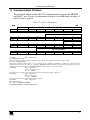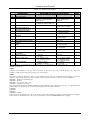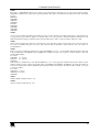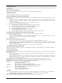
1
Kramer Electronics, Ltd.
USER MANUAL
Model:
VP-23N
Presentation Switcher
Contents
Contents
1
2
2.1
3
3.1
3.2
3.3
3.4
4
5
6
6.1
6.2
6.3
6.4
6.5
Introduction
Getting Started
Quick Start
Overview
Shielded Twisted Pair (STP) / Unshielded Twisted Pair (UTP)
About the VP-23N
Recommendations for Achieving the Best Performance
Terminology Used in this User Manual
Your Presentation Switcher
Installing the VP-23N on a Rack
Connecting the VP-23N Presentation Switcher
Connecting the VP-23N Rear Panel
Wiring the CAT5 LINE OUT RJ-45 Connector
Connecting a PC
Connecting via RS-485
Controlling via ETHERNET
1
1
1
3
3
3
4
5
5
11
12
12
15
16
17
18
6.5.1
6.5.2
6.5.3
Connecting the ETHERNET Port directly to a PC (Crossover Cable)
Connecting the ETHERNET Port via a Network Hub (Straight-Through Cable)
Control Configuration via the Ethernet Port
18
20
20
6.6
6.7
Controlling via RS-232 and RS-485
Dipswitch Settings
20
22
6.7.1
Setting the Machine # Dipswitches
22
7
7.1
7.2
7.3
8
8.1
8.2
8.3
9
10
10.1
11
Operating Your Switcher
The Front Panel Buttons
The Independent Switchers Mode
The Master Audio Mode
Flash Memory Upgrade
Downloading from the Internet
Connecting the PC to the RS-232 Port
Upgrading Firmware
Technical Specifications
Hex Table
Audio Gain Control Hex Tables
Communication Protocol
23
23
25
26
28
28
28
29
34
35
35
37
i
Contents
Figures
Figure 1: VP-23N Presentation Switcher – Front View
Figure 2: VP-23N Presentation Switcher – Rear View
Figure 3: VP-23N Presentation Switcher– Underside View
Figure 4: Connecting the VP-23N Presentation Switcher
Figure 5: CAT5 PINOUT
Figure 6: Connecting a PC without using a Null-modem Adapter
Figure 7: Controlling via RS-485 (for example, using an RC-3000)
Figure 8: RJ-45 PINOUT
Figure 9: Local Area Connection Properties Window
Figure 10: Internet Protocol (TCP/IP) Properties Window
Figure 11: Control Configuration via RS-232 and RS-485
Figure 12: Default Dipswitch Settings
Figure 13: Separate Switcher Mode
Figure 14: Switching in the Master Audio Mode
Figure 15: Splash Screen
Figure 16: Atmel – Flip Window
Figure 17: Device Selection Window
Figure 18: Selecting the Device from the Selection Window
Figure 19: Loading the Hex
Figure 20: RS-232 Window
Figure 21: Atmel – Flip Window (Connected)
Figure 22: Atmel – Flip Window (Operation Completed)
6
8
10
14
15
16
17
18
19
19
21
22
25
27
29
29
30
30
31
31
32
33
Tables
Table 1: Terminology Used in this User Manual
Table 2: Front Panel VP-23N Presentation Switcher Features
Table 3: Rear Panel VP-23N Presentation Switcher Features
Table 4: VP-23N Underside Panel Feature
Table 5: CAT5 PINOUT
Table 6: Crossover Cable RJ-45 PINOUT
Table 7: Straight-through Cable RJ-45 PINOUT
Table 8: Dipswitch Settings
Table 9: Machine # Dipswitch Settings
Table 10: Technical Specifications of the VP-23N Presentation Switcher
Table 11: VP-23N Hex Table
Table 12: VP-23N Master Audio Selector Hex Table
Table 13: Set the Audio Output Gain Control for the Groups
Table 14: Set the Audio Output Gain Control for the Microphone
Table 15: Set the Audio Output Gain Control for the Master Audio
Table 16: Increase or Decrease the Audio Output Gain by One Step
Table 17: Protocol Definitions
Table 18: Instruction Codes
ii
5
7
9
10
15
18
20
22
22
34
35
35
35
35
36
36
37
38
KRAMER: SIMPLE CREATIVE TECHNOLOGY
Introduction
1
Introduction
Welcome to Kramer Electronics (since 1981): a world of unique, creative and
affordable solutions to the infinite range of problems that confront the video, audio
and presentation professional on a daily basis. In recent years, we have redesigned
and upgraded most of our line, making the best even better! Our 500-plus different
models now appear in 8 Groups1, which are clearly defined by function.
Congratulations on purchasing your Kramer VP-23N Presentation Switcher,
which is ideal for presentation and conference room systems, production
studios, rental and staging.
The package includes the following items:
VP-23N Presentation Switcher
Windows®-based Kramer control software
Windows®-based Configuration Manager XPort software and Com Port
Redirector
Null-modem adapter and power cord2
Kramer RC-IR1 Infra-Red Remote Control Transmitter3 (including the
required battery and a separate user manual4)
This user manual4
2
Getting Started
We recommend that you:
Unpack the equipment carefully and save the original box and packaging
materials for possible future shipment
Review the contents of this user manual
Use Kramer high performance high resolution cables5
2.1 Quick Start
This quick start chart summarizes the basic setup and operation steps.
1 GROUP 1: Distribution Amplifiers; GROUP 2: Video and Audio Switchers, Matrix Switchers and Controllers; GROUP 3:
Video, Audio, VGA/XGA Processors; GROUP 4: Interfaces and Sync Processors; GROUP 5: Twisted Pair Interfaces;
GROUP 6: Accessories and Rack Adapters; GROUP 7: Scan Converters and Scalers; and GROUP 8: Cables and Connectors
2 We recommend that you use only the power cord that is supplied with this machine
3 Previously known as the IR-1 / IR-1-01
4 Download up-to-date Kramer user manuals from our Web site at http://www.kramerelectronics.com
5 The complete list of Kramer cables is on our Web site at http://www.kramerelectronics.com
1
Getting Started
UXGA CAT5 OUT
Connect to a
remote acceptor
(CAT5 receiver)
Separate 4x1 A/V Switchers
Press a button to select an input (from 1 to 4)
on each switcher (CV, s-Video and/or
VGA/UXGA) to route to the appropriate output.
Selected input buttons illuminate
Adjust MIC Volume
Press + (increase)
or - (decrease)
buttons to adjust
MIC signal Level
2
Mute the Audio
Buttons
Press the illuminated
button for more than 2
seconds
Adjust MASTER
Volume
Press + (increase)
or - (decrease)
buttons to adjust
audio signal Level
Master Audio Mode
Select the master audio button
to switch a selected input audio
signal (one of the 3 selected
inputs in the switcher groups)
or the MIC input to the master
outputs: MASTER OUT and/or
SPKR OUT
To Talk Over the master audio
output with the microphone:
Press the Talk Over button.
Press the MIC AUDIO LEVEL
buttons to increase or decrease
microphone volume
KRAMER: SIMPLE CREATIVE TECHNOLOGY
Overview
3
Overview
This section describes:
Using shielded twisted pair (STP)/unshielded twisted pair (UTP), see section 3.1
A summary of the VP-23N, see section 3.2
Recommendations for achieving the best performance, see section 3.3
The terminology used in this user manual, see section 3.4
3.1 Shielded Twisted Pair (STP) / Unshielded Twisted Pair (UTP)
The decision whether to use shielded twisted pair (STP) cable or unshielded
twisted pair (UTP) cable depends on the nature of the application.
It is recommended that in applications with high interference, shielded
twisted pair (STP) cable will give better results. However, the shield itself
does create a capacitance that degrades the frequency response of the
machines. For shorter distances, of 50m or so, shielded twisted pair (STP)
cable is preferred because it provides protection from interference
(degradation is non apparent).
For a long range application, unshielded twisted pair (UTP) cable is preferred.
However, the unshielded twisted pair (UTP) cable should be installed far away
from electric cables, motors etc., which are prone to create electrical interference.
Some Kramer twisted pair products include the Power Connect feature1. The
VP-23N does not have this feature.
3.2 About the VP-23N
The VP-23N is a high quality one-box presentation switcher, which includes
three independent 4x1 audio/video switchers and a master audio switcher. It
combines the functions of a 4x1 switcher for composite video and audio, a
4x1 switcher for s-Video and audio, and a 4x1 switcher for computer graphics
(VGA/UXGA) signals with audio, as well as the master audio switcher that
routes one of the pre-selected audio inputs (from these three switchers) to two
separate outputs.
1 The Power Connect feature lets you power a transmitter / receiver system by connecting just one power adapter to either the
transmitter or the receiver. The other unit is fed over the same CAT5 cable. The Power Connect feature applies as long as the
CAT5 cable is heavy gauge cable (that is, it can carry power). The distance does not exceed 50 meters on standard cable. For
a distance of 100 meters, separate power supplies must be connected to the transmitter and to the receiver simultaneously,
unless using heavy gauge CAT5 cable
3
Overview
In addition, the VP-23N:
Has a VGA/UXGA video bandwidth of 350MHz to ensure transparent
performance even in the most critical applications, and is HDTV compatible
Has a composite/SDI video bandwidth of 650MHz, an s-Video bandwidth
of 385MHz, and a CAT5 bandwidth of 158MHz
Includes 16 selector buttons, digital microphone input level control and
digital master audio level control
Features a microphone talk-over mode (the microphone input signal lowers
the line audio output level when the connected microphone detects sound)
Has a CAT5 output, with a transmission range of more than 300 feet (over
100 meters) that transmits XGA signals to a remote acceptor via a
receiver
Includes an internal 5-Watt per channel (24kHz, 3dB), power amplifier
for connecting the speakers directly to the machine
Has a panel LOCK button to prevent tampering with the front panel
Recalls the previous setup via the non-volatile memory after power up
Supports changing the audio output levels via RS-232 commands
Control the VP-23N using the front panel buttons, or remotely via:
RS-485 or RS-232 serial commands transmitted by a touch screen system,
PC, or other serial controller
The Kramer Infra-Red remote control transmitter
The ETHERNET
3.3 Recommendations for Achieving the Best Performance
To achieve the best performance:
Connect only good quality connection cables, thus avoiding interference,
deterioration in signal quality due to poor matching, and elevated noiselevels (often associated with low quality cables)
Avoid interference from neighboring electrical appliances and position
your Kramer VP-23N away from moisture, excessive sunlight and dust
4
KRAMER: SIMPLE CREATIVE TECHNOLOGY
Your Presentation Switcher
3.4 Terminology Used in this User Manual
Table 1 defines some terms that are used in this user manual.
Table 1: Terminology Used in this User Manual
Term
Definition
The standard specification for ETHERNET that is maintained by the Institute of Electrical
and Electronics Engineers (IEEE).
Dynamic Host
Allows the network administrator to distribute IP addresses from a central point and
Configuration
automatically send a new IP address when an Ethernet point is plugged into a different
Protocol (DHCP)
network location
Gateway
A network position serving as an entry to another network. On the Internet, a node or
stopping point can be either a gateway node or a host (end-point) node.
IP Address
A 32-binary digit number that identifies each sender or receiver (within a network via a
particular server or workstation) of data (HTML pages or e-mails) that is sent in packets
across the Internet. Every device connected to an IP network must have a unique IP
address. This address is used to reference the specific unit.
Local Area Network Computers sharing a common communications line or wireless link, which often share a
(LAN)
server within a defined geographic area.
Media Access
A computer's unique hardware number (or address) in a LAN or other network. On an
Control (MAC)
Ethernet LAN, the (MAC) address is identical to the Ethernet address.
Address
Transmission
The basic communication language or protocol of the Internet that breaks the message
Control
into appropriately sized packets for the network, and can be used as a communications
Protocol/Internet
protocol in an intranet or an extranet.
Protocol (TCP/IP)
802.3
4
Your Presentation Switcher
Figure 1, Figure 2, Table 2 and Table 3 describe the front and rear panels of
the VP-23N, respectively.
5
Your Presentation Switcher
Figure 1: VP-23N Presentation Switcher – Front View
6
KRAMER: SIMPLE CREATIVE TECHNOLOGY
Your Presentation Switcher
Table 2: Front Panel VP-23N Presentation Switcher Features
#
1
Feature
IR (Infra-Red) Receiver
2
3
POWER Switch
VIDEO (CV)-AUDIO SELECTOR
Buttons
s-VIDEO (Y/C)-AUDIO SELECTOR
Buttons
VGA/UXGA-AUDIO SELECTOR
Buttons
CV Button
4
5
6
Function
Signals from the remote control transmitter illuminate the
LED
Illuminated switch supplying power to the unit
Selects the composite video-audio source (from 1 to 4)
Selects the s-Video-audio source (from 1 to 4)
Selects the VGA/UXGA video-audio source from (1 to 4)
Press to route the selected audio signal from the composite
video section to the master audio outputs1
s-VIDEO Button
Press to route the selected audio signal from the s-Video
1
MASTER
section to the master audio outputs
AUDIO
VGA/UXGA Button Press to route the selected audio signal from the
SELECTOR
1
VGA/UXGA section to the master audio outputs
MIC Button
Press to route the microphone input to the master audio
1
outputs
7
+ Button Increase the microphone audio signal level
MIC
8
- Button Decrease the microphone audio signal level
AUDIO LEVEL
9
+ Button Increase the master audio signal level
MASTER
10
- Button Decrease the master audio signal level
11 TALK OVER Button
Push the button to activate talk over2
12 LOCK Button
Press to lock the front panel buttons
1 MASTER OUT and SPKR OUT
2 With the TALK OVER button pressed in, speaking into the microphone amplifies the voice of the speaker, overriding and
fading out all other audio channels. However, pressing the MIC button in the Master Audio Selector renders the Talk Over
function inactive
7
Your Presentation Switcher
Figure 2: VP-23N Presentation Switcher – Rear View
8
KRAMER: SIMPLE CREATIVE TECHNOLOGY
Your Presentation Switcher
Table 3: Rear Panel VP-23N Presentation Switcher Features
4
5
6
7
8
9
10
11
12
13
14
15
16
17
18
19
20
21
22
23
AUDIO
3
Feature
Function
MIC IN Connector
Connect to the microphone
COND. / DYN Selector Switch Push in to select a condenser, push out to select a dynamic
microphone
CV OUT
Connect to the composite video balanced audio acceptor
Terminal Block Connector
Y/C OUT
Connect to the s-Video balanced audio acceptor
Terminal Block Connector
UXGA OUT
Connect to the VGA/UXGA balanced audio acceptor
Terminal Block Connector
1
MASTER OUT
Connect the master balanced audio channel acceptor
Terminal Block Connector
CV IN
Connect to the composite video balanced audio sources2
Terminal Block Connectors
SPKR OUT
Connect to a pair of loudspeakers
Terminal Block Connector
2
Y/C IN
Connect to the s-Video balanced audio sources
Terminal Block Connectors
2
UXGA IN
Connect to the VGA/UXGA balanced audio sources
Terminal Block Connectors
CV IN BNC Connectors
Connect to the composite video sources2
CV OUT BNC Connector
Connect to the composite video acceptor
Y/C IN 4p Connectors
Connect to the s-Video sources2
Y/C OUT 4p Connector
Connect to the s-Video acceptor
UXGA IN HD15 Connectors
Connect to the VGA/UXGA video sources2
UXGA OUT HD15 Connector Connect to the VGA/UXGA video acceptor
ETHERNET Connector
Connects to the PC or other Serial Controller through computer
networking
RS-232 DB 9F Port
Connects to the PC or the Remote Controller
FLASH PROG. Button
Push in for “Program” to upgrade to the latest Kramer firmware
(see section 8), or release for Normal (the factory default)3
RS-485 Terminal Block Port
Pins B (-) and A (+) are for RS-485; Pin G may be connected to
the shield (if required)
Dipswitches
Dipswitches for setup of the unit (DIPs 1, 2 and 3 are for
setting the machine # and DIP 4 is for RS-485 termination;
see section 6.7)
UXGA CAT5 OUT
Connect to a remote computer graphics acceptor via a
receiver (for example, the TP-1204)
Twisted Pair Connector
Power Connector with Fuse
AC connector enabling power supply to the unit
VIDEO
#
1
2
1 Both the MASTER OUT and the SPKR OUT terminal block connecters receive the same signal: the MASTER OUT
outputs it as it is while the SPKR OUT is amplified
2 From 1 to 4
3 The FLASH PROG reset button is located on the underside of the unit (see Figure 3)
4 See section 6.1
9
Your Presentation Switcher
Figure 3 and Table 4 define the RESET button (located on the machine’s
underside).
RESET
Figure 3: VP-23N Presentation Switcher– Underside View
Table 4: VP-23N Underside Panel Feature
Feature
RESET Button
10
Function
Press to reset the unit prior to firmware upgrade (see section
8.3)
KRAMER: SIMPLE CREATIVE TECHNOLOGY
Installing the VP-23N on a Rack
5
Installing the VP-23N on a Rack
This section describes what to do before installing on a rack and how to rack
mount.
Before Installing on a Rack
Before installing on a rack, be sure that the environment is
within the recommended range:
Operating temperature range +5 to +45 Deg. Centigrade
Operating humidity range
5 to 65 % RHL, non-condensing
Storage temperature range
-20 to +70 Deg. Centigrade
Storage humidity range
5 to 95% RHL, non-condensing
How to Rack Mount
To rack-mount the machine:
1
Attach both ear brackets to the
machine. To do so, remove the
screws from each side of the
machine (3 on each side), and
replace those screws through
the ear brackets.
CAUTION!!
When installing on a 19" rack, avoid hazards by taking care
that:
1
It is located within the recommended environmental
conditions, as the operating ambient temperature of a
closed or multi unit rack assembly may exceed the room
ambient temperature.
2
Once rack mounted, enough air will still flow around the
machine.
3
The machine is placed straight in the correct horizontal
position.
4
You do not overload the circuit(s). When connecting the
machine to the supply circuit, overloading the circuits
might have a detrimental effect on overcurrent
protection and supply wiring. Refer to the appropriate
nameplate ratings for information. For example, for fuse
replacement, see the value printed on the product label.
Detachable rack ears can be
removed for desktop use
The machine is earthed (grounded) in a reliable way
and is connected only to an electricity socket with
grounding. Pay particular attention to supply
connections other than direct connections to the branch
circuit (for example, the use of power strips), and that
you use only the power cord that is supplied with the
machine.
If you are using a Kramer rack
adapter kit (for a machine that is not
19"), see the Rack Adapters user
manual for installation instructions
(you can download it at:
http://www.kramerelectronics.com)
5
2
Place the ears of the machine
against the rack rails, and insert
the proper screws (not
provided) through each of the
four holes in the rack ears.
Note that:
In some models, the front panel
may feature built-in rack ears
Always mount the machine in the
rack before you attach any cables or
connect the machine to the power
11
Connecting the VP-23N Presentation Switcher
6
Connecting the VP-23N Presentation Switcher
This section describes how to:
Connect the rear panel (see section 6.1)
Wire the CAT5 connector (see section 6.2)
Connect a PC or other controller via the RS-232 port (see section 6.3)
Connect a controller via the RS-485 port (see section 6.4)
Control the VP-23N via the ETHERNET (see section 6.5)
Cascade several machines (see section 6.6)
Set the dipswitches (see section 6.7)
6.1 Connecting the VP-23N Rear Panel
In Figure 4, the audio connections are not shown, except for the microphone
and speakers connections.
In this example, all the outputs are connected to the same projector. Use the
projector controller to switch between the VP-23N video outputs1.
To connect2 the VP-23N, as illustrated in Figure 4, do the following3:
1. Connect the following video sources:
One4 composite video source (for example, a composite video player)
to the CV IN 1 BNC connector
One4 s-Video source (for example, an s-Video player) to the Y/C IN 1
4p connector
One4 VGA/UXGA source (for example, a computer graphics source)
to the UXGA IN 1 HD15F connector
1 Or projector inputs
2 You do not need to connect all the inputs
3 Switch OFF the power on each device before connecting it to your VP-23N. After connecting your VP-23N, switch on its
power and then switch on the power on each device. Switching on the VP-23N, recalls the previous setup from the nonvolatile memory
4 Although in this example only one source is connected, you can connect all of the four inputs, that is, 12 in total
12
KRAMER: SIMPLE CREATIVE TECHNOLOGY
Connecting the VP-23N Presentation Switcher
2. Connect the acceptors to a projector1 as follows:
The composite video CV OUT BNC connector to the composite video
input of the projector
The s-Video Y/C OUT 4p connector to the s-Video input of the
projector
The VGA/UXGA UXGA OUT HD15F connector to the VGA/UXGA
input of the projector
3. Connect the appropriate balanced audio sources and acceptors (not shown in
Figure 4).
4. Connect the MASTER OUT terminal block connector, if required (not shown
in Figure 4; see section 7.3).
5. Connect the SPKR OUT block connector to a pair of loudspeakers, by
connecting the left loudspeaker to the “L+” and the “L-” terminal block
connectors, and the right loudspeaker to the “R+” and the “R-” terminal block
connectors. Do not Ground the loudspeakers.
6. Connect the UXGA CAT5 OUT twisted pair connector (see section 6.2) to a
line receiver (for example, the TP-120 XGA Line Receiver2, which is
connected to a remote display).
7. Connect a dynamic or a condenser microphone3, if required, to the MIC IN
XLR connector.
8. As an option, you can connect a PC and/or controller to:
The RS-232 port (see section 6.3)
The RS-485 port (see section 6.4)
The ETHERNET (see section 6.5)
9. Connect the unit to additional machines (if required) via the RS-485 port (see
section 6.6).
10. Connect the power cord.
1 In this example a projector is used, but you can also connect separate outputs such as displays, video recorders and so on
2 The receiver receives the CAT5 signal, decodes it and outputs it to a VGA acceptor
3 Use the Con / Dyn switch (refer to the rear panel, item 2 in Figure 2) to select a dynamic microphone or a condenser
13
Connecting the VP-23N Presentation Switcher
s-Video
Player
Speakers
Composite
Video
Player
RS-232
Computer
Graphics Source
Display
Projector
Figure 4: Connecting the VP-23N Presentation Switcher
14
KRAMER: SIMPLE CREATIVE TECHNOLOGY
Connecting the VP-23N Presentation Switcher
6.2 Wiring the CAT5 LINE OUT RJ-45 Connector
Table 5 and Figure 5 define the CAT5 PINOUT, using a straight pin-to-pin
cable with RJ-45 connectors:
Table 5: CAT5 PINOUT
EIA /TIA 568A
PIN
1
2
3
4
5
6
7
8
Wire Color
Green / White
Green
Orange / White
Blue
Blue / White
Orange
Brown / White
Brown
Figure 5: CAT5 PINOUT
EIA /TIA 568B
PIN
1
2
3
4
5
6
7
8
Wire Color
Orange / White
Orange
Green / White
Blue
Blue / White
Green
Brown / White
Brown
Pair 1
4 and 5
Pair 1
Pair 2
3 and 6
Pair 2
4 and 5
1 and 2
Pair 3
1 and 2
Pair 3
3 and 6
Pair 4
7 and 8
Pair 4
7 and 8
15
Connecting the VP-23N Presentation Switcher
6.3 Connecting a PC
You can connect a PC (or other controller) to the VP-23N via the RS-232 port.
To connect using the Null-modem adapter provided with the machine
(recommended method):
Connect the RS-232 DB9 rear panel port on the VP-23N to the
Null-modem adapter and connect the Null-modem adapter with a 9-wire
flat cable to the RS-232 DB9 port on your PC
To connect without using a Null-modem adapter:
Connect the RS-232 DB9 port on your PC to the RS-232 DB9 rear panel
port on the VP-23N, as Figure 6 illustrates
PIN 5 Connected to PIN 5 (Ground)
PIN 3 Connected to PIN 2
PIN 2 Connected to PIN 3
Female DB9 (From PC)
Male DB9
PIN 4 Connected to PIN 6
PINS 8, 7, 1 Connected together
If a Shielded cable is used, connect the shield to PIN 5
Figure 6: Connecting a PC without using a Null-modem Adapter
16
KRAMER: SIMPLE CREATIVE TECHNOLOGY
Connecting the VP-23N Presentation Switcher
6.4 Connecting via RS-485
You can control a VP-23N unit via an RS-485 controller, or a Master
Programmable Remote Control system such as the Kramer RC-30001.
To connect an RC-3000 to a VP-23N unit (see Figure 7), connect the RS-485
terminal block port on the RC-3000 to the RS-485 port on the VP-23N unit,
as follows:
Connect the “A” (+) PIN on the RS-485 rear panel port of the RC-3000 to
the “A” (+) PIN on the RS-485 rear panel port of the VP-23N unit
Connect the “B” (-) PIN on the RS-485 rear panel port of the RC-3000 to
the “B” (-) PIN on the RS-485 rear panel port of the VP-23N unit
If shielded twisted pair cable is used, the shield may be connected to the
“G” (Ground) PIN on one of the units (for example, on the RC-3000)
Set the VP-23N unit to a Machine # other than 1, according to Table 9,
and set DIP 4 ON (for RS-485 Line Termination with 120 )
RS-485 PINOUT
G
_ B
+ A
KEYBOARD EXTENSION
OUT
IN
1 2 3 4 5 6 7 8 9 10 11 12 13 14 15 16
REMOTE CONTACT
1 2 3
4 5
6
7
8 G
RS-485
RS-232 IN
RS-232 OUT
12 VDC
Figure 7: Controlling via RS-485 (for example, using an RC-3000)
1 Previously known as the VS-3000
17
Connecting the VP-23N Presentation Switcher
6.5 Controlling via ETHERNET
You can connect the VP-23N via the Ethernet, using a crossover cable (see
section 6.5.1) for direct connection to the PC or a straight through cable (see
section 6.5.2) for connection via a network hub or network router1.
6.5.1
Connecting the ETHERNET Port directly to a PC (Crossover Cable)
You can connect the Ethernet port of the VP-23N to the Ethernet port on your
PC, via a crossover cable with RJ-45 connectors, as Table 6 and Figure 8
define.
Figure 8: RJ-45 PINOUT
Table 6: Crossover Cable RJ-45 PINOUT
EIA /TIA 568A
Side 1
PIN
Wire Color
1
White-orange
2
Orange
3
White-green
4
Blue
5
White-blue
6
Green
7
White-brown
8
Brown
EIA /TIA 568B
Side 2
PIN
Wire Color
1
White-green
2
Green
3
White-orange
4
Blue
5
White-blue
6
Orange
7
White-brown
8
Brown
Pair 1
4 and 5
Pair 1
Pair 2
1 and 2
Pair 2
3 and 6
Pair 3
3 and 6
Pair 3
1 and 2
Pair 4
7 and 8
Pair 4
7 and 8
4 and 5
This type of connection is recommended for identification of the factory default
IP Address of the VP-23N during the initial configuration
After connecting the Ethernet port, configure your PC as follows:
1. Right-click the My Network Places icon on your desktop.
2. Select Properties.
1 After connecting the Ethernet port, you have to install and configure your Ethernet Port and also install the COM Port
Redirector. For detailed instructions, see the “Ethernet Configuration (Lantronix) guide.pdf” file in the technical support
section on our Web site: http://www.kramerelectronics.com
18
KRAMER: SIMPLE CREATIVE TECHNOLOGY
Connecting the VP-23N Presentation Switcher
3. Right-click Local Area Connection Properties.
4. Select Properties.
The Local Area Connection Properties window appears.
5. Select the Internet Protocol (TCP/IP) and click the Properties Button (see
Figure 9).
Figure 9: Local Area Connection Properties Window
6. Select Use the following IP Address, and fill in the details as shown in
Figure 10.
7. Click OK.
Figure 10: Internet Protocol (TCP/IP) Properties Window
19
Connecting the VP-23N Presentation Switcher
6.5.2
Connecting the ETHERNET Port via a Network Hub (Straight-Through
Cable)
You can connect the Ethernet port of the VP-23N to the Ethernet port on a
network hub or network router, via a straight-through cable with RJ-45
connectors, as Table 7 defines:
Table 7: Straight-through Cable RJ-45 PINOUT
PIN
1
2
3
4
5
6
7
8
6.5.3
Side 1
Wire Color
White-orange
Orange
White-green
Blue
White-blue
Green
White-brown
Brown
PIN
1
2
3
4
5
6
7
8
Side 2
Wire Color
White-orange
Orange
White-green
Blue
White-blue
Green
White-brown
Brown
Control Configuration via the Ethernet Port
To control several units via the Ethernet, connect the Master unit
(Machine # 1) via the Ethernet port to the LAN port of your PC. Use your PC
initially to configure the settings (see section 6.5).
6.6 Controlling via RS-232 and RS-485
You can cascade up to eight VP-23N units with control from a PC or serial
controller.
To cascade up to eight individual VP-23N units, via RS-232 and RS-485, as
illustrated in Figure 11, do the following:
1. Connect the video sources and acceptors, as well as the appropriate audio
sources and acceptors, as described in section 6.1.
2. Connect the RS-232 port on the first VP-23N unit to the PC using the
Null-modem adapter provided with the machine (recommended), as section
6.3 describes.
3. Connect the RS-485 terminal block port on the first VP-23N unit to the
RS-485 port on the second VP-23N unit and so on, connecting all the RS-485
ports.
4. Set the dipswitches, as section 6.7.1 describes. In particular:
Set the first VP-23N unit as Machine # 1, the second unit to Machine
# 2, and so on - up to Machine # 8 for the eighth unit
Set Dip 4 ON on the first and last VP-23N units (terminating the
RS-485 line at 120 ). On the other units, set DIP 4 OFF
20
KRAMER: SIMPLE CREATIVE TECHNOLOGY
Connecting the VP-23N Presentation Switcher
Machine # 1 (Master)
Machine # 2
Up to 8
Units
Machine # 8
Figure 11: Control Configuration via RS-232 and RS-485
21
Connecting the VP-23N Presentation Switcher
6.7 Dipswitch Settings
Figure 12 and Table 8 define the factory default dipswitch settings1:
OFF
ON
1 2 3 4
Figure 12: Default Dipswitch Settings
Table 8: Dipswitch Settings
6.7.1
DIPS
1, 2, 3
Function
Machine #
Description
Determines the number of the machine in the sequence
4
RS-485 TERM
ON for RS-485 Line Termination with 120 ;
OFF for no RS-485 Line Termination
Setting the Machine # Dipswitches
You can cascade up to eight VP-23N units. The Machine # determines the
position of a VP-23N unit, specifying which VP-23N unit is being controlled
when several VP-23N units connect to a PC or serial controller. Set the
Machine # on a VP-23N unit via Setup DIPS 1, 2 and 3, according to Table 9.
Table 9: Machine # Dipswitch Settings
Machine
#
1
Dipswitch
2
3
1 Master
2
OFF OFF
OFF OFF
OFF
ON
3
OFF ON
OFF
4
OFF ON
ON
5
ON
OFF
OFF
6
ON
OFF
ON
7
ON
ON
OFF
8
ON
ON
ON
1 By default, all dipswitches are set to OFF
22
KRAMER: SIMPLE CREATIVE TECHNOLOGY
Operating Your Switcher
7
Operating Your Switcher
This section describes the:
Front panel buttons (see section 7.1)
Separate switchers mode (see section 7.2)
Master audio switcher mode (see section 7.3)
7.1 The Front Panel Buttons
The front panel buttons include the:
VIDEO (CV)-AUDIO SELECTOR buttons (1 to 4)
S-VIDEO (Y/C)-AUDIO SELECTOR buttons (1 to 4)
VGA/UXGA-AUDIO SELECTOR buttons (1 to 4)
MASTER AUDIO SELECTOR buttons (CV, S-VIDEO, VGA/UXGA
and MIC)
TALK OVER button1, which lowers or mutes the MASTER AUDIO
LEVEL when the microphone picks up speech2
MIC AUDIO LEVEL up and down buttons to adjust the level at the
master audio out3 connectors4 and the talk-over function threshold5
MASTER AUDIO LEVEL up and down buttons to adjust the audio
output level at the master audio out connectors3, without influencing any
other audio output
Panel LOCK button to lock the front panel buttons
6
By default , the stereo audio signals switch together with the video, that is, the
7
unit is set in an audio-follow-video (AFV) mode. You can change to
8
breakaway mode , via RS-232.
1 Two channels are active in the Talk Over mode, a source selected via the MASTER AUDIO SELECTOR buttons and the
microphone channel
2 Adjust the microphone level via the MIC AUDIO LEVEL + and - buttons
3 MASTER OUT and SPKR OUT
4 Useful in the TALK OVER mode, when the microphone level needs to be adjusted separately
5 Achieving optimum results for a particular environment when using a microphone may require experimentation in adjusting
the AUDIO and MIC LEVELS
6 This is, the pre-installed factory default. The default can be modified via the Windows®-based Kramer control software
7 In which all operations relate to both the video and the audio channels
8 In which video and audio channels switch independently
23
Operating Your Switcher
Pressing an illuminated AUDIO SELECTOR button for more than 2 seconds
disconnects that master audio output, and the button no longer illuminates.
The video will continue to display but without sound.
The Master Audio automatically follows the last input selected (for example,
VGA/UXGA), regardless of the switcher group (VGA, s-Video, or composite
video), and the respective button1 under the MASTER AUDIO SELECTOR
section illuminates, indicating that the selected input (for example,
VGA/UXGA) is routed to the master outputs.
1 Replacing the previous illuminated button
24
KRAMER: SIMPLE CREATIVE TECHNOLOGY
Operating Your Switcher
7.2 The Independent Switchers Mode
In the independent switchers mode, the three switchers of the VP-23N operate
independently from each other, as illustrated in Figure 13. You can route one
of the 4 CV inputs, one of the 4 Y/C inputs and one of the 4 VGA/UXGA
inputs to the corresponding CV, Y/C and UXGA1 outputs, respectively.
To switch an input to an output2:
Press one3 button from the set of 4 buttons in the VIDEO (CV)-AUDIO
SELECTOR section and/or4
One button from the set of 4 buttons in the s-VIDEO (Y/C)-AUDIO
SELECTOR section and/or
One button from the set of 4 buttons in the VGA/UXGA-Audio
SELECTOR section
Each pressed button illuminates5, indicating selection and outputting of that
video and audio source.
UXGA Acceptor
UXGA Sources
CV Video Sources
s-Video Sources
Video Acceptor
s-Video Acceptor
Speakers
Figure 13: Separate Switcher Mode
1 And to the UXGA CAT5 OUT connector
2 Assuming that all inputs are connected
3 You cannot select more than one button in a section
4 You can overlook a section and choose not to select a button from it
5 Pressing an illuminated button for more than 2 seconds will disconnect the output and the button will no longer illuminate
25
Operating Your Switcher
7.3 The Master Audio Mode
In the master audio mode, you can route an audio input signal from any of the
A/V switchers or from the microphone, to the MASTER OUT and/or SPKR
OUT outputs.
Figure 14 shows a plasma-display connected to the VP-23N unit via the
UXGA OUT HD15F connector, and a pair of speakers connected to the SPKR
OUT terminal block connector.
(I) When pressing button 2 under the VGA/UXGA-AUDIO SELECTOR, the
UXGA IN 2 signal is routed to the display1. The VGA/UXGA button under
the MASTER AUDIO SELECTOR section automatically illuminates, and the
UXGA audio signal is routed to the SPKR OUT2 and the MASTER OUT2
terminal block connectors simultaneously3.
(II) After connecting a microphone to the MIC IN XLR connector, the MIC
button under the MASTER AUDIO SELECTOR section illuminates and the
speakers output the MIC IN4 audio signal, while retaining the UXGA display.
You can return to the UXGA audio output by pressing the VGA/UXGA
button under the MASTER AUDIO SELECTOR section once again.
1 The UXGA output is simultaneously routed to the UXGA CAT 5 OUT connector
2 The MASTER audio signal is routed simultaneously to the SPKR OUT and the MASTER OUT channels. The only
difference between them is that the SPKR OUT channel has an internal power amplifier, which lets you connect the speakers
directly to the unit
3 As well as to the AUDIO UXGA OUT terminal block connector, which is not connected in this example
4 Another way to use the microphone is to press the TALK OVER button: the main audio level is lowered when the
microphone picks up speech
26
KRAMER: SIMPLE CREATIVE TECHNOLOGY
Operating Your Switcher
I
II
I
UXGA Source
II
Presenter’s
Microphone
Speaker
Speaker
Display
Figure 14: Switching in the Master Audio Mode
27
Flash Memory Upgrade
8
Flash Memory Upgrade
The VP-23N firmware is located in FLASH memory, which lets you upgrade
to the latest Kramer firmware version in minutes! The process involves:
Downloading from the Internet (see section 8.1)
Connecting the PC to the RS-232 port (see section 8.2)
Upgrading Firmware (see section 8.3)
8.1 Downloading from the Internet
You can download the up-to-date file1 from the Internet. To do so:
1. Go to our Web site at http://www.kramerelectronics.com and download the
file: “FLIP_VP23N.zip” from the Technical Support section.
2. Extract the file: “FLIP_VP23N.zip” to a folder (for example, C:\Program
Files\Kramer Flash).
3. Create a shortcut on your desktop to the file: “FLIP.EXE”.
8.2 Connecting the PC to the RS-232 Port
Before installing the latest Kramer firmware version on a VP-23N unit, do the
following:
1. Connect the RS-232 DB9 rear panel port on the VP-23N unit to the
Null-modem adapter and connect the Null-modem adapter with a 9-wire flat
cable to the RS-232 DB9 COM port on your PC (see section 6.3).
2. On the rear panel, push in the FLASH PROG button (to program), using a
screwdriver.
3. Connect the power on the VP-23N unit and switch it ON.
4. On the underside panel, push in the RESET FOR PROGRAM button (see
Figure 3), using a screwdriver.
1 The files indicated in this section are given as an example only. These file names are liable to change from time to time
28
KRAMER: SIMPLE CREATIVE TECHNOLOGY
Flash Memory Upgrade
8.3 Upgrading Firmware
Follow these steps to upgrade the firmware:
1. Double click the desktop icon: “Shortcut to FLIP.EXE”.
The Splash screen appears as follows:
Figure 15: Splash Screen
2. After a few seconds, the Splash screen is replaced by the “Atmel –Flip”
window:
Figure 16: Atmel – Flip Window
3. Press the keyboard shortcut key F2 (or select the “Select” command from the
Device menu, or press the integrated circuit icon in the upper right corner of the
window).
The “Device Selection” window appears:
29
Flash Memory Upgrade
Figure 17: Device Selection Window
4. Click the button next to the name of the device and select from the list:
AT89C51RD2:
AT89C51RD2
T89C51RD2
Figure 18: Selecting the Device from the Selection Window
5. Click OK and select “Load Hex” from the File menu.
30
KRAMER: SIMPLE CREATIVE TECHNOLOGY
Flash Memory Upgrade
A
Figure 19: Loading the Hex
6. The Open File window opens. Select the correct HEX file that contains the
updated version of the firmware for VP-23N (for example, 23NM_V1p2.hex)
and click Open.
7. Press the keyboard shortcut key F3 (or select the “Communication / RS232”
command from the Settings menu, or press the keys: Alt SCR).
The “RS232” window appears. Change the COM port according to the
configuration of your computer and select the 9600 baud rate:
Figure 20: RS-232 Window
8. Click Connect.
In the “Atmel –Flip” window, in the Operations Flow column, the Run button
is active, and the name of the chip appears as the name of the third column:
AT89C51RD2.
31
Flash Memory Upgrade
Verify that in the Buffer Information column, the “HEX File: VP23N.hex”
appears.
A
VP23N.hex
Figure 21: Atmel – Flip Window (Connected)
9. Click Run.
After each stage of the operation is completed, the check-box for that stage
becomes colored green1.
When the operation is completed, all 4 check-boxes will be colored green and
the status bar message: Memory Verify Pass appears2:
1 See also the blue progress indicator on the status bar
2 If an error message: “Not Finished” shows, click Run again
32
KRAMER: SIMPLE CREATIVE TECHNOLOGY
Flash Memory Upgrade
A
VP23N.hex
Figure 22: Atmel – Flip Window (Operation Completed)
10. Close the “ Atmel –Flip” window.
11. Disconnect the power on the VP-23N.
12. Disconnect the RS-232 rear panel port on the VP-23N unit from the
Null-modem adapter.
13. Release the FLASH PROG button on rear panel.
14. Connect the power to the VP-23N.
33
Technical Specifications
9
Technical Specifications
Table 10 includes the technical specifications1:
Table 10: Technical Specifications of the VP-23N Presentation Switcher
INPUTS:
OUTPUTS:
MAX. OUTPUT LEVEL:
BANDWIDTH (-3dB):
DIFF. GAIN:
DIFF. PHASE:
K-FACTOR:
S/N RATIO:
CROSSTALK (all hostile):
CONTROLS:
COUPLING:
AUDIO THD + NOISE@1kHZ:
AUDIO 2nd HARMONIC:
POWER SOURCE:
DIMENSIONS:
WEIGHT:
ACCESSORIES:
4 VGA / XGA on HD15F connectors
4 s-Video, 1 Vpp (Y), 0.3Vpp (C) / 75 on 4 pin connectors
4 composite video 1Vpp / 75 on BNC connectors
Each input is accompanied by the appropriate balanced stereo-audio
channels: +4dBm / 50 k on detachable terminal block connectors
Mic: 3mV / 10 k condenser / dynamic on an XLR connector
1 x VGA / XGA on an HD15F connector
1 s-Video - 1 Vpp (Y), 0.3Vpp (C), / 75 on 4 pin connector
1 composite video 1 Vpp / 75 on a BNC connector
1 UTP CAT5 connector (Line OUT)
Each output is accompanied by the appropriate balanced stereo-audio
channel: +4dBm / 150 on detachable terminal blocks
1 master stereo audio +4dBm / 150 on a detachable 4-pin terminal block
1 stereo speaker output 2x5W continuous into 4
VIDEO: YC: 1.8Vpp; CV: 1.8Vpp
AUDIO: Group: 20dBm
XGA: 1.7Vpp; CAT5: 1.3Vpp
Master: 15dBm
VIDEO: YC: 385MHz; CV: 650MHz
AUDIO: Group: 46kHz
XGA: 350MHz; CAT5: 158MHz
Speakers: 40kHz
Master: 33kHz
YC: 0.03%; CV: 0.03%; CAT5: 6.4%; XGA: 0.15%
YC: 0.03 Deg.; CV: 0.03 Deg.; CAT5: 0.2 Deg.; XGA: 0.09 Deg.
<0.1%
VIDEO: YC: 81dB; CV: 75dB
AUDIO: Group: 74dB
CAT5: 59dB; XGA: 75dB (unweighted) Speakers: 53dB (max pwr weighted)
Master out: 72dB
VIDEO: 49dB @5MHZ
AUDIO: Group: < -76dB
Master: < -69dB @1kHz
Channel selector for video and audio, for YC, CV and XGA; master audio
output selector, audio level, talkover, lock
VIDEO: YC, CV and XGA: DC
AUDIO: AC, input and output
Group: 0.08%; Speakers: 2% (max pwr); Master: 0.25%
Group: 0.065%; Speakers: 1.6% (max pwr); Master: 0.155%
100-240VAC, 50/60Hz, 35VA
19-inch (W), 7-inch (D) 2U (H) rack-mountable
3.8 kg (8.4 lbs.) approx.
Power cord, infra-red remote control transmitter, PC control software,
Windows®-based Configuration Manager XPort software and Com Port
Redirector
1 Specifications are subject to change without notice
34
KRAMER: SIMPLE CREATIVE TECHNOLOGY
Hex Table
10 Hex Table
Table 11 lists the Hex values (which the protocol in section 11 describes in
more detail) for the VP-23N Presentation Switcher:
Table 11: VP-23N Hex Table
Inputs
VGA
s-Video
Composite
Video
Group
#
In 1
In 2
In 3
In 4
In 1
In 2
In 3
In 4
In 1
In 2
In 3
In 4
Composite Video
OUT and Audio
OUT CV
01 81 81 81
01 82 81 81
01 83 81 81
01 84 81 81
s-Video OUT and
Audio OUT s-Video
VGA OUT and
Audio OUT VGA
01 81 82 81
01 82 82 81
01 83 82 81
01 84 82 81
01 81 83 81
01 82 83 81
01 83 83 81
01 84 83 81
Table 12: VP-23N Master Audio Selector Hex Table
Master Audio Selector (Group Audio OUT)
Composite Video Audio OUT
s-Video Audio OUT
VGA Audio OUT
Microphone
Disconnect All
10.1
Audio Master OUT
02 81 81 81
02 82 81 81
02 83 81 81
02 84 81 81
02 80 81 81
Audio Gain Control Hex Tables
The following tables describe the audio gain controls.
Table 13: Set the Audio Output Gain Control for the Groups
Composite Video
16 81 80 81
Audio Gain Control for Groups
s-Video
VGA
16 82 80 81
16 83 80 81
Notes
Mute
… …
… …
… …
16 81 EC 81
16 82 EC 81
16 83 EC 81
0dB (1:1)
16 81 FF 81
16 82 FF 81
16 83 FF 81
9dB
Table 14: Set the Audio Output Gain Control for the Microphone
Audio Gain Control for Microphone
16 84 80 81
Mute
… …
16 84 CD 81
16 84 FF 81
Maximum
35
Hex Table
Table 15: Set the Audio Output Gain Control for the Master Audio
Audio Gain Control for Master Out
16 85 80 81
Mute
16 85 F9 81
… …
0dB
16 85 FF 81
3dB
Table 16: Increase or Decrease the Audio Output Gain by One Step
s-Video
VGA
Microphone
Master Out
Increase
Composite
Video
18 81 80 81
18 82 80 81
18 83 80 81
18 84 80 81
18 85 80 81
Decrease
18 81 81 81
18 82 81 81
18 83 81 81
18 84 81 81
18 85 81 81
36
KRAMER: SIMPLE CREATIVE TECHNOLOGY
Communication Protocol
11 Communication Protocol
This protocol, which enables RS-232 communication between the VP-23N
and the PC, uses 4 bytes of information, and data is at 9600 baud, no parity, 8
data bits and 1 stop bit.
Table 17: Protocol Definitions
MSB
LSB
INSTRUCTION
DESTINATION
0
7
D
6
N5
5
N4
4
N3
3
N2
2
N1
1
0
6
0
5
0
4
0
3
I2
2
I1
1
1
7
0
6
0
5
0
4
0
3
0
2
O1
1
1
7
0
6
0
5
0
4
M3
3
N0
0
1st byte
INPUT
1
7
I0
0
2nd byte
OUTPUT
3rd byte
O0
0
MACHINE NUMBER
M2
2
M1
1
M0
0
4th byte
1st BYTE:
Bit 7 – Defined as 0.
D – “ DESTINATION BIT” .
This bit is always low, when sending from the PC to the switchers, and high for information sent to the PC.
N5…N0 – “ INSTRUCTION” .
These 6 bits define the function that is to be performed by the switcher(s). Similarly, if a function is performed via the
machine’s keyboard, then these bits are set with the INSTRUCTION NO, which was performed. The instruction codes are
defined according to the table below (INSTRUCTION NO. is the value to be set for N5…N0).
2nd BYTE:
Bit 7 – Defined as 1.
Bits 3 – 6 - Defined as 0.
I2… I0 – “ INPUT” .
For disconnect, set as 0. For other operations, these bits are defined according to Table 18.
3rd BYTE:
Bit 7 – defined as 1.
Bits 2-6 defined as 0.
O1, O0 – “ OUTPUT”
For operations, these bits are defined according to Table 18.
4th BYTE:
Bit 7 – Defined as 1.
Bits 3-6 Defined as 0.
M3… M0 – “ MACHINE NUMBER” .
MACHINE NUMBER = (DIPSWITCH CODE) + 1.
37
Communication Protocol
Table 18: Instruction Codes
#
INSTRUCTION
DESCRIPTION
DEFINITION FOR SPECIFIC INSTRUCTION
INPUT
OUTPUT
0
1
RESET MACHINE
SWITCH GROUPS
2
SWITCH AUDIO OUTPUTS
5
REQUEST GROUP STATUS
6
REQUEST STATUS OF
MASTER AUDIO OUTPUT
BREAKAWAY SETTING
0
REQUEST BREAKAWAY
SETTING
ERROR
0
8
11
16
18
22
25
RESET MACHINE
SET AUDIO GAIN OF AUDIO
OUTPUT
INCREASE/DECREASE AUDIO
GAIN
REQUEST GAIN
30
LOCK FRONT PANEL
31
57
REQUEST WHETHER PANEL
IS LOCKED
SET AUTO SAVE
61
IDENTIFY MACHINE
62
DEFINE MACHINE
24
0
1-4 Set equal to video and audio
inputs to be switched for the
relative group
1-5* Set equal to audio output to
be switched to Master Audio out
0
0
Don’t care
0
1-5*
1-5*
1-5*
0 – Panel unlocked
1 – Panel locked
0
1 – Autosave
2 – No save
1 or 2 – Machine name
3 or 4 – Program version
1 – Number of inputs
2 – Number of outputs
0
1-3 Set equal to group to
which output is to be
switched
1
NOTE
1
2
2
1-3 Set equal to the group of
which status is required
1
3
0 – Audio-follow-video
1 – Audio breakaway
0
3
0 – Invalid instruction
1 – Out of range
0
Gain value
1
7
0 – Increase gain
1 – Decrease gain
0 – Video gain
1 – Audio gain
0
3
2
4
8
3, 9
0
3
Don’t care
5
0 – request first 4 digits
1 – request first suffix
10 – request first prefix
1 – For video
2 – For audio
6
3
* 1 – for CV group, 2 – for SV group, 3 – for VGA group, 4 – for microphone, 5 – for master audio out
NOTES on to Table 18:
NOTE 1
When the master switcher is reset, (e.g. when it is turned on), the reset code is sent to the PC. If this code is sent to the
switchers, it will reset according to the present power-down settings.
NOTE 2
These are bi-directional definitions. That is, if the switcher receives the code, it will perform the instruction; and if the
instruction is performed (due to a keystroke operation on the front panel), then these codes are sent. For example, if:
0000 0001 Instruction “ Switch Groups”
1000 0010 Input #2
1000 1001 in composite video group
1000 0001 Machine #1 (master)
Was sent from the PC, then the switcher (machine #1) will switch input 2 in composite video group to its output. If the user
switched input 4 in the VGA group via the front panel keypad, then the switcher will send:
0100 0001
1000 0100
1000 0011
1000 0001 to the PC.
When the PC sends instruction #1 or #2 to the switcher, then, if the instruction is valid, the switcher replies by sending the
same four bytes to the PC that were sent (except for the first byte, where the DESTINATION bit is set high).
38
KRAMER: SIMPLE CREATIVE TECHNOLOGY
Communication Protocol
NOTE 3
The reply to a “ REQUEST” instruction is as follows: the same instruction and input codes as were sent are returned, and the
OUTPUT is assigned to the value of the requested parameter. The reply to the instruction #5 (what is the status of the VGA
group?):
0000 0101
1000 0000
1000 0011
1000 0001
Would be:
0100 0101
1000 0000
1000 0100
1000 0001
NOTE 4
An error code is returned to the PC if an invalid code was sent to the switcher (for example, when trying to switch an input or
a group which is greater than the highest one defined). This code is also returned to the PC if an RS-232 instruction is sent
while the machine is being programmed via the front panel. Reception of this code by the switcher will not be valid.
NOTE 5
Under normal conditions, the machine’s present status is saved each time a change is made. The power-down save (the auto
save) may be disabled using this code. Note that each time that the machine is turned ON, the auto save function is
automatically set.
NOTE 6
This is a request to identify the switchers in a system. If the INPUT is set as 1 or 2, the machine will send its name. The reply
is the decimal value of the INPUT and the OUTPUT. For example, the reply to the request to send the machine’s name (for
machine #001) will be:
0111 1101
1000 0000 (i.e. 128+0)
1001 0111 (i.e. 128+23)
1000 0001
If the request for identification is sent with the INPUT set as 3 or 4, the appropriate machine will send its software version
number. Again, the reply would be the decimal value of the INPUT and OUTPUT - the INPUT representing the number in
front of the decimal point, and the OUTPUT representing the number following the decimal point. For example, for version
3.5 the reply will be:
0111 1101
1000 0011 (i.e. 128+3)
1000 0101 (i.e. 128+5)
1000 0001
NOTE 7
GAIN VALUE – Number from 0 to 127
NOTE 8
Answer = Current Audio Gain (0 –127)
39
LIMITED WARRANTY
Kramer Electronics (hereafter Kramer) warrants this product free from defects in material and workmanship under the
following terms.
HOW LONG IS THE WARRANTY
Labor and parts are warranted for seven years from the date of the first customer purchase.
WHO IS PROTECTED?
Only the first purchase customer may enforce this warranty.
WHAT IS COVERED AND WHAT IS NOT COVERED
Except as below, this warranty covers all defects in material or workmanship in this product. The following are not covered
by the warranty:
1.
2.
3.
Any product which is not distributed by Kramer, or which is not purchased from an authorized Kramer dealer. If you are
uncertain as to whether a dealer is authorized, please contact Kramer at one of the agents listed in the Web site
www.kramerelectronics.com.
Any product, on which the serial number has been defaced, modified or removed.
Damage, deterioration or malfunction resulting from:
i)
Accident, misuse, abuse, neglect, fire, water, lightning or other acts of nature
ii)
Product modification, or failure to follow instructions supplied with the product
iii)
Repair or attempted repair by anyone not authorized by Kramer
iv)
Any shipment of the product (claims must be presented to the carrier)
v)
Removal or installation of the product
vi)
Any other cause, which does not relate to a product defect
vii)
Cartons, equipment enclosures, cables or accessories used in conjunction with the product
WHAT WE WILL PAY FOR AND WHAT WE WILL NOT PAY FOR
We will pay labor and material expenses for covered items. We will not pay for the following:
1.
2.
3.
Removal or installations charges.
Costs of initial technical adjustments (set-up), including adjustment of user controls or programming. These costs are the
responsibility of the Kramer dealer from whom the product was purchased.
Shipping charges.
HOW YOU CAN GET WARRANTY SERVICE
1.
2.
3.
To obtain service on you product, you must take or ship it prepaid to any authorized Kramer service center.
Whenever warranty service is required, the original dated invoice (or a copy) must be presented as proof of warranty coverage,
and should be included in any shipment of the product. Please also include in any mailing a contact name, company, address, and
a description of the problem(s).
For the name of the nearest Kramer authorized service center, consult your authorized dealer.
LIMITATION OF IMPLIED WARRANTIES
All implied warranties, including warranties of merchantability and fitness for a particular purpose, are limited in duration to
the length of this warranty.
EXCLUSION OF DAMAGES
The liability of Kramer for any effective products is limited to the repair or replacement of the product at our option. Kramer
shall not be liable for:
1.
2.
Damage to other property caused by defects in this product, damages based upon inconvenience, loss of use of the product, loss
of time, commercial loss; or:
Any other damages, whether incidental, consequential or otherwise. Some countries may not allow limitations on how long an
implied warranty lasts and/or do not allow the exclusion or limitation of incidental or consequential damages, so the above
limitations and exclusions may not apply to you.
This warranty gives you specific legal rights, and you may also have other rights, which vary from place to place.
NOTE: All products returned to Kramer for service must have prior approval. This may be obtained from your dealer.
This equipment has been tested to determine compliance with the requirements of:
EN-50081:
"Electromagnetic compatibility (EMC);
generic emission standard.
Part 1: Residential, commercial and light industry"
EN-50082:
"Electromagnetic compatibility (EMC) generic immunity standard.
Part 1: Residential, commercial and light industry environment".
CFR-47:
FCC Rules and Regulations:
Part 15: “ Radio frequency devices
Subpart B – Unintentional radiators”
CAUTION!
Servicing the machines can only be done by an authorized Kramer technician. Any user who makes changes or modifications to
the unit without the expressed approval of the manufacturer will void user authority to operate the equipment.
Use the supplied DC power supply to feed power to the machine.
Please use recommended interconnection cables to connect the machine to other components.
40
KRAMER: SIMPLE CREATIVE TECHNOLOGY
For the latest information on our products and a list of Kramer
distributors, visit our Web site: www.kramerelectronics.com,
where updates to this user manual may be found.
We welcome your questions, comments and feedback.
Safety Warning:
Disconnect the unit from the power supply before
opening/servicing.
Caution
Kramer Electronics, Ltd.
Web site: www.kramerelectronics.com
E-mail: [email protected]
P/N: 2900–000110 REV 1A