1
NIRC2 Programmer’s Manual
1Overview
3
1.1Instrument Description
3
1.2Mechanisms 3
2.1Mechanism numbering
4
2.2Motor controlled mechanisms 4
2.3Thermal mechanisms 5
2.4Calibration Lamps
5
1.3Software Architecture 5
2Motor Daemon
5
2.1RPC Functions
6
1.1Data Structures
7
1.2Motor command codes
8
1.3Adding new motor command codes to support new motor operations
2.2Configuration File Format (nirc2_motor.config) 11
2.1Communications link specifications
11
2.2Motor specifications 11
2.3Motor characteristics 12
2.4Adding new motor characteristics
15
2.3Logging And Debugging
16
2.4Support Programs
17
4.1Tellmotor
17
4.2Askmotor
18
4.3Loadmotor 18
4.4Motorinfo
20
4.5Motorprop
20
2.5Building and releasing 21
3I/O Daemon
21
3.1RPC Functions
22
1.1Data structures
23
1.2Adding new I/O types 24
3.2Configuration File Format (nirc2_io.config)
24
2.1Communications link specifications
25
2.2I/O device specification
25
2.3I/O device characteristics
26
3.3Logging And Debugging
27
3.4Support Programs
27
4.1Askdevice
28
4.2Telldevice
29
4.3Showdevinfo 29
3.5Building and releasing 30
4Keyword Library
31
4.1Mechanism keywords 32
1.1Keyword naming conventions 32
1.2Mechanism keyword types
33
1.3Mechanism operations relating to keyword suffixes
33
1.4Miscellaneous mechanism keywords
54
1.5Adding new mechanism functions (suffixes)
55
4.2Motor keywords
56
2.1Generic motor keywords
57
2.2Motor−specific keywords
63
2.3Miscellaneous motor keywords 68
11
4.3I/O keywords 69
3.1Analog keywords
70
3.2Digital keywords
71
3.3Set point keywords
71
3.4Temperature keywords
72
4.4User keywords
73
4.5Configuration Files
74
5.1Nirc2_config_file (keyword characteristics)
74
5.2Nirc2_mechanisms.config (mechanism characteristics)
77
5.3Wheel mechanisms’ details files
79
5.4Slider mechanisms’ details files
80
4.6Asynchronous keyword updates (monitors and events)
80
4.7Log files
81
4.8Error notification
82
8.1tklogger
82
4.9Building and releasing 82
5Troubleshooting Guide 83
5.1Environment variables to control logging
84
5.2Keywords to control logging 84
6Simulation
84
6.1Mechanism simulation
85
6.2Motor simulation within the keyword library
85
6.3I/O device simulation within the keyword library 87
6.4Motor simulation within the motor daemon
88
7Pupil Mask Rotator
88
8User scripts
88
9Animatics Motor Controllers
88
9.1Animatics motor programs
89
1.1Downloading and uploading motor controller programs 90
10DGH Devices (calibration lamps and cryogenic controls) 91
11Lakeshore Devices (temperature control and monitoring) 91
12Source directories
92
12.1/kroot/kss/ir_common
92
12.2/kroot/kss/nirc2
93
1
Overview
This document defines the software architecture for the NIRC2 instrument in regards to
mechanisms other than the detector system.
This document should be reviewed by programmers prior to modifying the software or for an
understanding of the underlying software.
1.1 Instrument Description
The NIRC2 instrument is a near−infrared camera intended to provide high−resolution imaging in
conjunction with the adaptive optics system on the Keck II telescope. The instrument will
feature a Boeing 1024^2 Aladdin III InSb detector, providing diffraction−limited imaging in the
J, H, and K pass bands (1−5 um range) with sensitivity between 5 and 10 times that of NIRC1.
The instrument contains three plate scales, providing fields−of−view measuring 10,20, and 40
arc seconds; these correspond to the diffraction limit for imaging at 1, 2, and 4 um, respectively.
The instrument also provides corona graphic imaging and diffraction limits spectroscopy over
the 1−5 um range a R=5000.
The principal investigator is K. Matthews (Caltech) and the co−investigator is T. Soiffer.
The detector electronics was developed by the IR lab at UCLA and is essentially identical to
NIRSPEC. The detector readout is performed by a transputer system. The UCLA team also
developed the software for the detector readout, and the associated user interface. This document
does not address the UCLA software, that information is available in UCLA generated
documents (enumerate here!!!)
1.2 Mechanisms
The instrument contains: eleven electro−mechanical mechanisms where the motors are external
to the dewar; a single−stage and a dual−stage cold head; a Lakeshore temperature controller; a
Lakeshore temperature monitor, and a controller for the calibration lamps.
The calibration lamps are on a stage on the adaptive optics bench and it is the AO software and
electronics, which moves the selected lamp into position. . The on/off control of the lamps is
handled by a DGH digital I/O module and is interfaced by software described within this
document.
Communications to all mechanisms is via serial I/O of one form or another. The mechanisms’
serial links are connected to one of two terminal servers and the software, running on a UNIX
host computer, interfaces to the mechanisms via the terminal server ports using TCP/IP.
The mechanisms are logically categorized as either motor controller mechanisms or i/o
mechanisms where a daemon task exists for each category as described in sections ‘’ and ‘’. The
interface to those daemon tasks is via a keyword library, which provides higher−level abstraction
of the mechanisms such that clients are insulated from the communications details of each
mechanism’s command syntax and protocol.
2.1 Mechanism numbering
Information pertaining to each of the mechanisms is encoded in a set of configuration files that
are read when the daemon tasks initialize (nirc2_motor.config and nirc2_io.config). There is also
a configuration file, which is read by the keyword library pertaining to the mechanisms,
nirc2_mechanism.config.
The mechanism configuration file specifies a unique number for each mechanism, which is
referred to as the ‘major mechanism numbers’. The motor and I/O configuration files, read by
the daemon tasks, associate a ‘minor mechanism number’ with each major mechanism number.
The minor numbers are essentially the addresses to which a specific remote devices will respond
thus the minor numbers must be unique for a given communication link but need not be unique
across all devices/links. That is, each unique communication link may be connected to a device,
which responds to an address of 1, for instance.
In most cases clients need not know any of the mechanism numbers, however, if a user wishes to
bypass the keyword library and to interface to the daemon tasks via the support programs then
they must be aware of major mechanism numbers and understand that the daemon tasks will
convert the user supplied major mechanism numbers to minor mechanism numbers when
communicating with the remote devices (refer to sections and ‘’).
2.2 Motor controlled mechanisms
The motor driven mechanisms use Animatics Smartmotors that have their controllers and
incremental encoders integrated with the motors. The motors’ serial interface is RS−485, which
provides for interconnecting the motors in a star configuration. Ten of the motors are connected
in a star configuration with the pupil mask rotator being independently connected. The motor
commands are all ASCII strings without any binary protocol or checksum. The motor addresses,
however, are not ASCII printable characters (refer to the Animatics User Manual).
One of the motor driven mechanisms is the shutter.
Six of the motor driven mechanisms are essentially linear translation stages, which are referred
to within this document as sliders. The slider mechanisms are the camera selector, grism, slit, slit
mask, inner preslit, and outer preslit. For the purposes of mechanism control software the shutter
is also classified as a slider.
Three of the motor driven mechanisms are rotational mechanisms (wheels), which are typically
driven to discrete locations so as to place specific filters and such in the light path. The ‘wheel’
mechanisms are the inner filter wheel, outer filter wheel, and the pupil mask selector.
The remaining motor driven mechanism is the pupil mask rotator that rotates in a tracking mode
following the telescope elevation angle and the adaptive optics image rotator. The software to
drive this mechanism is considerably different from that which drives the other motor controlled
mechanisms; the differences are thoroughly covered in subsections of this document.
All of the motor driven mechanisms, with the exception of the shutter have a homing switch and
two ends of travel switches.
2.3 Thermal mechanisms
As previously mentioned the thermal mechanisms are a single stage cold head, dual stage cold
head, temperature controller and temperature monitor.
Embedded within the coldhead control electronics are various DGH analog and digital modules.
The host control software communicates with the DGH modules via RS−232 serial links, which
are connected to terminal server ports.
The Lakeshore temperature controller and monitor also have RS−232 serial links connected to
terminal server ports.
All of the thermal mechanisms have ASCII string command sets without any protocol or
checksum.
2.4 Calibration Lamps
The calibration lamps’ power is controlled with the instrument software via a DGH digital output
module, which is connected to a terminal server port. The lamps are physically mounted on a
stage on the AO bench. The lamp positions are controlled by the AO software and electronics.
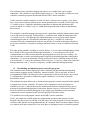
1.3 Software Architecture
The software to control the aforementioned mechanisms has been subdivided into four main
components, each of which is discussed in detail within this document.
The four main software components are: a body of software referred to as the ‘motor daemon’
whose interface is via remote procedure calls (RPC) and whose function is to act as the
communications interface to the motors; a body of software referred to as the ‘i/o daemon’
whose interface is also RPC and whose function is to act as the communications interface to the
non−motor devices; a keyword library which provides a higher level interface to the daemons
via the Keck tasking library (KTL); and the pupil mask rotator (PMR) control software which is
distinct from the keyword library and motor daemon.
2
Motor Daemon
The interface to the NIRC2 motors is via a body of software referred to as the motor daemon.
The motor daemon is responsible for converting motor demands and requests into syntactically
correct motor−specific commands (Anmiatics language). Note that only subsets of the Animatics
commands are encoded in the motor daemon and, therefore, a finite set of possible calls exist.
The implemented calls are enumerated in subsequent subsections.
The motor daemon is a standalone task, which is intended to be executed when the NIRC2
control system host is booted.
Communications with the motor daemon is via a set of remote procedure calls (RPC), which are
enumerated in subsequent subsections.
The normal mechanism for interfacing with the motor daemon is via the Keck tasking library
(KTL). This includes user command line use of ‘show’, ‘xshow’, and ‘modify’, as well as, scripts
and client programs. However, it is possible to create client programs that bypass the keyword
layer and directly communicate with the motor daemon via RPC calls. Such is the case of the
standalone programs such as tellmotor and askmotor (refer to section ‘’).
For each motor type, which is supported by the motor daemon, a motor−specific module must
exit, hopefully, in an appropriately named subdirectory. As of November 2000, the motor
daemon supports Animatics Smartmotor controllers and hooks have been added for
Compumotor (utilized in generation 1 Keck IR instruments) and API (used in SHARC and
OSIRIS). During startup configuration files are read and parsed. Some of the parsing is handled
by functions in the motor−specific module animatics.c.
Irrespective of the underlying motor type, all keyword library interactions with the motor
daemon are via a set of RPC functions, which are intended to be device independent. In most
cases, the RPC functions ultimately call functions in the motor specific modules. The motor−
specific modules’ functions are not addressed herein. However, the RPC functions are discussed
in the following subsections.
2.1 RPC Functions
As previously mentioned, the interface to the motor daemon is via a set of RPC functions. The
intent is that the keyword software and/or client programs need not know any of the underlying
motor−specific commands/language but, rather, that certain motor functions are supported. The
keyword library translates the mechanism and motor keywords into the appropriate RPC calls to
the motor daemon, thus the following information is provided for the requirements imposed on
any new client programs.
Rather than creating a specific RPC function for every possible motor function, or subset
thereof, the motor functions were grouped into two main classes, which are handled by two
distinct RPC functions, and six other special purpose RPC functions.
The two main classes are motor commands and motor requests, which are respectively handled
by motorcmd_1() and motorsts(). The six special purpose RPC functions are tellmotor_1(),
askmotor_ 1(), setmotorprop_1(), getmotorprop_1(), findmotor_1(), and motorinfo_1().
In the following subsections there are frequent references to ‘client’. One client is the keyword
library itself, which uses most if not all of the RPC functions. However, the keyword library is
not, and need not be, the only client. For instance the motor−daemon support programs (refer to
Section ) are also clients.
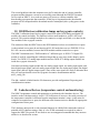
1.1 Data Structures
The nature of an RPC interface is such that each rpc function takes a pointer to an argument,
which may be a scalar or a structure, and returns a pointer to a scalar or structure. It is the calling
program’s responsibility to free the memory for the returned item.
The data structures for the motor daemon rpc functions are mtrInfo(), mtrMsg(), mtrProp(),
mtrStrReply(), and mtrReply(), which are defined in motor.h and derived from motor.x
Note that the data structures returned from RPC calls must be explicitly deallocate with
xdr_free(). If this were not done then a memory leak would exist.
1.1 MtrInfo
The mtrInfo structure is used in two of the motor daemon RPC calls (motorcmd_1, and
motorsts_1). This structure allows a client to specify a <motor, command, value> tuple for
affecting motor behavior.
The mtrInfo structure consists of three fields: an integer field ’motor’, which must be set to
the major−motor number (refer to section ‘’) of the motor to be affected by the command;
another integer field ’code’ which is one of the enumeration MOTOR_ CODES defined in
controller.h and discussed as needed in the RPC functions subsections; and a float field
’value’ which is the command specific parameter for the motor.
1.2 MtrMsg
The mtrMsg structure is used in two of the motor daemon RPC calls (tellmotor_1 and
askmotor_ 1). This structure allows a client to send arbitrary command strings to a motor. The
string is not parsed or interpreted in any way; hence, it is the client’s responsibility to ensure the
command string is valid with respect to the motor controller’s command syntax.
The mtrMsg structure consists of two fields: an integer field ’motor’, which must be set to the
major−motor number (refer to section ‘’) of the motor to be affected by the command;
and a character pointer (string) ‘field msg’, which is the command string to be sent to the
motor. Client programs must allocate the space for the string fields.
1.3 MtrProp
The mtrProp structure is used in the motor daemon’s setmotorprop_1 RPC call. This structure
allows clients to store arbitrary <name, value> strings in a hash table within the motor daemon.
The intent is to store values which a client would later retrieve for internal used. This concept is
discussed in more detail within a subsection about ‘user variables’ within the Keyword Library
documentation (refer to subsection ‘’).
The mtrProp structure consists of two character pointer fields (strings), namely, ’name’ and
’value’. The client must allocate the space for the strings.
1.4 MtrStrReply
The mtrStrReply structure is returned to a client in response to an askmotor_1, getmotorprop_1,
or motorinfo_1 RPC call. All of these calls return string data to the client.
The mtrStrReply structure consists of a status field (a value of 1 means success), an error
message string (typically set when the status is not 1), and a reply message string.
1.5 MtrReply
The mtrReply structure is returned to a client in response to RPC calls, which do not return a
string. The structure only provides for scalar values.
The mtrReply structure consists of: a status field which is set to 1 on success; an error message
string which is typically set when the status is not 1; a flag field which indicates whether or not
the value is returned as a double or integer value; an long integer value field which is set to the
return value if the integer flag field is set; and a double real value field which is set to the return
value if the integer flag field is not set. Note that the integer flag field is controlled within the
motor specific protocol routine, which, in this case, is handled within animatics.c.
1.2 Motor command codes
When a client attempts a motor command or request, an RPC call is ultimately invoked. A set of
C routines exists in motor.c to translate client calls into the relevant RPC calls. In most cases the
RPC call involves a mtrMsg structure (discussed above). Within that mtrMsg structure is a
command code, which are interpreted by the motor specific protocol routines within
animatics.c). The valid command codes are hard coded as an enumeration within controller.h.
Not all command codes are implemented within animatics.c (refer to section to extend the
available Animatics functions).
The intent of the motor command codes is to separate motor operations from motor command
specifics such that a generic set of motor operations can be derived. Which of those motor
operations can be applied to a given motor type is then dependent upon the implementation
within the motor specific module included in the motor daemon; in the case of NIRC2 the
module is animatics.c.
To paraphrase, a client should use the functions in motor.c to perform common motor operations
as doing so will hide not only the motor specifics (command language) and RPC calls, but also
the motor command codes needed to depict the operation.
The functions within motor.c, which implement the motor operations, are documented in the
relevant subsections of the keyword library. However the motor operations that are implemented
for the NIRC2 Animatics motor controllers, and for which motor command codes exist in
controller.h, are enumerated in the following list.
0* Home a motor, this invokes a subroutine in the motor
controller’s non−volatile memory
1* Return a motor’s current homed state, the state is retained in a
motor controller variable that is set at the end of controller’s
homing subroutine
2* Return a motor’s current idle status, a motor controller
variable is set at the beginning of each of its subroutines and
clear at the end of those subroutines
3* Initialize a motor, this invokes a subroutine in the motor
controller’s non−volatile memory which set the controller’s
control dynamics to safe defaults
4* Return a motor’s current initialized state, the state is
retained in a motor controller variable which is set at the end
of its initialization subroutine
5* Return a motor’s current limit status, this used motor
controller commands to determine the motor was last stopped due
to an encounter with a travel limit
6* Return a motor’s current CCW software limit, this is a value
cached in the motor daemon and is the largest negative encoder
value that a client may specify in an absolute move command
7* Return a motor’s current CW software limit, this is a value
cached in the motor daemon and is the largest positive encoder
value that a client may specify in an absolute move command
8* Return a motor’s current control status, this is a composite of
a motor’s various travel limit and fault statuses which is
assembled from the responses to several motor controller
commands
9* Return a motor’s motor type, this is a numeric value that motor
daemon associated with a given motor type
10*Return a motor’s motor position in encoder counts
11*Return a motor’s current shutdown state
12*Return a motor’s current stall fault state
13*Return a motor’s current communications overflow fault state
14*Return a motor’s current over−temperature fault state
15*Enable/disable echo mode, one can instruct the Animatics
Smartmotors echo all commands they receive
16*Set a motor’s acceleration value
17*Set a motor’s maximum current value
18*Set a motor’s maximum position error value
19*Set a motor’s maximum velocity
20*Set a motor’s backlash offset value, this is retained in a
motor controller variable and is the distance moved at the end
of a motor move in order to accommodate for backlash
21*Set/release a motor’s brakes, this is typically not used during
operations as brakes control is automatically performed at the
beginning and end of motor motions but is provided as a
troubleshooting and debugging function. Setting a motor’s brakes
reduces current flow and heat generation.
22*Enable/disable a motor’s servo/power−on state, this is
typically not used during operations as brakes control is
automatically performed at the beginning and end of motor
motions but is provided as a troubleshooting and debugging
function. Disabling a motor reduces current flow and heat
generation.
23*Perform a software reset on a motor
24*Decelerate a motor to a stop
25*Abruptly stop a motor (kill)
26*Move a motor to a specific encoder position; this is an
absolute move, which is accomplished, via a subroutine in a
motor controller’s non−volatile memory. The subroutine handles
brake control, power/servo control, and any backlash removal.
27*Move a motor relative to its current position; this is a delta
move, which is accomplished via a subroutine in a motor
controller’s non−volatile memory. The subroutine handles brake
control, power/servo control, and any backlash removal.
28*Invoke a special motion routine, this is a subroutine within
the motor controller’s non−volatile memory which is identified
in nirc2_motor.config file on daemon startup (refer to section
‘’)
29*Set a motor’s trace level, this is retained in the motor daemon
and provides increasingly detailed feedback of the daemon’s
actions
30*Return a motor’s current trace level
31*Set a motor’s simulation level, when enabled interactions with
a motor does not occur but a set of software simulation routines
are invoked instead
32*Return a motor’s simulation level
1.3 Adding new motor command codes to support new motor operations
At some point in time it may be necessary to support additional motor operations, perhaps in
response to new motor controller subroutines. To do so one would need to extend the motor code
enumerations (motor codes in controller.h) and then add a case statement to one or both of
animaticsSts() and animaticsCmd() within animatics.c.
2.2 Configuration File Format (nirc2_motor.config)
When the motor daemon initializes it reads and parses the records contained in a configuration
file. The configuration file is specified in the default script, which is provided as a daemon
command line argument. Throughout this manual the configuration file is referred to as
nirc2_motor.config, however it is possible to change this in the default script, which one may
wish to do for testing and/or trouble−shooting.
The motor configuration file has three functions: to identify the communications links; to
identify the motors connected to a given link; and to specify the motor characteristics of each of
those motors.
More than one communications link may be specified, but all motors and their characteristics,
for a given link, must be specified before another link is specified. That is, all motor information
following a communications link is assumed to be relevant to the communications link, up to the
point that another communications link is specified.
2.1 Communications link specifications
The purpose of the communications link specification is to identify the communications device
to which one or more motor controllers are connected.
The motor controllers may be connected to a host (UNIX machine) serial port, in which case the
syntax would be:
serial <port name>
Where the ‘port name’ is the string as specified in the host’s device table (e.g., /dev/term/b).
Alternatively, the motor controllers may be connected to a terminal server port, in which case
the syntax would be:
ethernet <host id> <port number>
Where ‘host id’ would be the terminal server name/ip address and ‘port number’ is the terminal
server port to which the controller is connected (e.g., ethernet nirc2_ts 3002).
2.2
Motor specifications
For each motor connected to a communications link there must be a motor specification
followed by several motor−characteristic specifications.
The syntax for the motor spec is:
motor=<motor type> <major−motor number> <minor−motor number>
{icd=<microseconds>}{rxd=<microseconds>}
Where:
The motor type is Animatics for NIRC2.
The ‘major−motor number’ or instrument−wide number which must unique within this
configuration file, this motor number must correlate with the number specified for a given
mechanism in the mechanism−configuration file (refer to section ‘’).
The ‘minor−motor number’ is the motor address or number to which a specific motor
controller will respond, this need not be unique as two motors on two different
communications links may have the same motor address.
‘icd’ is an inter−character delay used when writing to the communications link, if ‘icd’ is not
specified then characters are output in bursts and fragmentation by the UNIX driver and/or
terminal server may have an affect;
‘rxd’ is the receiver delay (typically 2 to 3 seconds), which specifies the maximum amount of
time for which a reply will be awaited, if a reply takes longer than the receiver delay then an
error will be logged.
2.3 Motor characteristics
Each motor possesses a set of characteristics, which can be specified in the motor configuration
file. The characteristics and, consequently, the syntax for those characteristics is motor type
specific therefore the parsing of the characteristics is encoded in the motor specific module,
which, for NIRC2, is animatics.c.
The exact set of characteristics required depends upon the Animatics subroutines that are stored
in the controllers.
Each characteristic must exist on a separate line in the configuration file where the syntax is:
<characteristic>={<value> | <command string>}
Note a command string must be enclosed in double quotes.
In the case of a command string, the motor daemon always formats the motor address (refer to
the Animatics SmartMotor User’s Manual), and inserts it at the beginning of the string, prior to
sending the command string to a motor controller. However the Animatics Smartmotor firmware
used in the NIRC2 controllers will always respond to commands which are not preceded by a
motor address, thus it is necessary to embed motor addresses in command strings when the
command strings contain more than a single motor command. The syntax for embedded motor
addresses –in fact any non−printable ASCII value− is to specify the value as an octal value
preceded by a ‘\’ character. These backslash sequences are parsed/translated by the routines in
animatics.c when the configuration file is read. As an example the string “\202Ra” would specify
a request for motor controller 2 to return the current value of it’s ‘a’ variable
A command string may also require that a value other than the motor number be embedded prior
to sending the command string to a motor. For instance a motor motion subroutine may need a
variable set to the destination prior to being run. This is permitted by the use of ‘%’, similar to
the C printf statement, albeit only integer and single precision floats are needed. As an example
the string “\202d=%d \202g=2 \202RUN” would set motor controller 2’s ‘d’ variable to a user
specified value (this is actually the absolute move command string as ‘g’ is used to specify which
motor controller subroutine to run).
In general, entries exist in the motor configuration file for motor characteristics, which require
an implementation specific motor controller command string (perhaps to use a subroutine in the
motor controller’s non−volatile memory), utilize a motor controller variable, or are parameters
that may be dynamically changed.
The characteristics, which the functions in animatics.c will recognize, are discussed in the
following subsections. Examples for each characteristic can be found in the operation
configuration file nirc2_motor.config.
3.1 Resolution
The motor resolution specifies the number of encoder counts per motor shaft revolution. For
NIRC2 the characteristic tag is ‘resolution’ or ‘motorres’ or ‘mr’. In retrospect this should
probably have been hard−coded as a default such that an entry would exist in the configuration
file if a different motor were ever substituted.
3.2 Negative software limit
The negative software limit is the largest negative encoder position that a client is permitted to
specify as a motor destination. If this value is exceeded then the motion command will be
rejected and an error will be logged. For NIRC2 the characteristic tag is ‘low_ml’ or
‘low_motion_limit’ or ‘negative_limit’ or ‘neg_limit’ or ‘min_position’ or ‘min_posn’.
3.3 Positive software limit
The positive software limit is the largest encoder position that a client is permitted to specify as a
motor destination. If this value is exceeded then the motion command will be rejected and an
error will be logged. For NIRC2 the characteristic tag is ‘high_ml’ or ‘high_motion_limit’ or
‘positive_limit’ or ‘pos_limit’ or ‘max_position’ or ‘max_posn’.
3.4 Motor dynamics
The motor control dynamics’ parameters are assumed to be set within a motor controller’s
initialization subroutine. These values can be changed with the appropriate keywords (refer to
the appropriate subsections within ‘’, ‘’, and ‘’). However characteristic tags exist in the motor
configuration file for a few of the values. The specified values are not used by the functions in
animatics.c and exist so that the motor simulator can function close to reality, that is, the values
in configuration file are fed back to functions in animaticsSim.c for when simulation is enabled
for a motor (refer to section ‘’).
The characteristic tags are: ‘acceleration’, ‘accel’, or ‘a’; ‘velocity’, ‘vel’, or ‘v’;
‘homing_velocity’, ‘homing_vel’, ‘homingvel’, or’hv’; ‘position_error’, ‘positionerr’, or ‘pe’; and
‘backlash’ or ‘bd’.
3.5 Backlash
A backlash correction has been programmed into the motion subroutines that are retained in the
motor controllers’ non−volatile memory. The values are retained in motor controller variables.
Characteristic tags exist in the motor configuration file for the purpose of setting and reading
back the backlash values. The characteristic tag for setting the backlash is ‘backlashcmd’ the tag
for the reading the current value is ‘backlashrbv’.
3.6 Position error
The motor controller’s subroutines use an internal variable for retaining the position error. This
was done so that the value can be dynamically changed. Of course this means that characteristics
tags must exist in the motor configuration file for the purpose of setting and retrieving the
values. The tag for setting the position error is ‘posnerrcmd’ and the tag for the read back is
‘posnerrrv’.
3.7 Brake control
The brake control specifies motor control sequences that are needed to either set or release a
motor’s brakes. For NIRC2 the brakes are controlled by output latch A which is controlled by
the Animatics user output command ‘UA’, such that ‘UA=1’ sets a brake and ‘UA=0’ releases a
brake. As two sequences are needed there are two characteristic tags, ‘brakeon’ and ‘brakeoff’.
3.8 Reset
The reset characteristic/keyword tag specifies the motor control commands needed to cause a
motor to perform its software reset. This was added as a characteristic so that a motor controller
subroutine could be invoked if necessary but such a subroutine was not created for the NIRC2
mechanisms, hence this could have been eliminated from the configuration file by hard coding
the reset command in the relevant function within animatics.c.
3.9 Initializing
The initialization characteristic also consists of three characteristic tags. The tag ‘init’ specifies
the command sequence required to initialize a motor, which basically sets the motor’s control
parameters to safe default value as the parameters after a reset, or power cycle will not allow a
motor to move.
The second characteristic tag is ‘isinit’ which specifies the motor controller commands needed to
fetch the initialization state. The init subroutine sets a motor controller variable to 1 when
initialization is complete and it is this variable which indicates whether or not a motor has been
initialized since the last reset or power cycle.
The third characteristic tag is ‘isinitval’ which specifies the value of the isinit characteristic,
which indicates that initialization, has been completed since the last reset or power cycle.
3.10 Homing
The homing characteristic consists of three characteristic tags. One of them is ‘home’ and
specifies a command sequence for homing a motor. A subroutine exists in the motor controllers’
non−volatile memories for homing.
Another characteristic tag ‘ishome’ specifies the motor controller commands needed to fetch the
homing status. The homing subroutine sets a motor controller variable to 1 when complete and it
is this variable, which is identified as the ishome characteristic.
Lastly the characteristic tag ‘ishomeval’ specifies the value of the ishome characteristic, which
indicates that homing has been completed since the last reset or power cycle of the motor in
question.
3.11 Motor motion sequences
Motor controller subroutines exist in the motor controllers’ non−volatile memories for moving
the motors to absolute or relative positions. The subroutines are needed to automatically release
and set brakes, enable and disable motor power, check for travel limit conditions, and to handle
backlash. The motor configuration file tags for the motions are ‘absmove’ and ‘relmove’.
3.12 Idle status
No single Animatics command exists to determine whether or not a motor is actually in an idle
state. So each of the motor controller subroutines, which move a motor, use a variable for this
purpose. The variable is set at the beginning of those subroutines and cleared at the end. Hence
two characteristic tags exist for determining if a motor is idle, ‘isidle’ is the command sequence
to get the variable’s value and ‘isidleval’ specifies the value, which indicates that the motor is
idle.
2.4
Adding new motor characteristics
It is feasible that at some point a new motor characteristic will be needed, perhaps this would
occur in response to a modification to one of the a motor controller subroutines that are
downloaded into the motor controllers’ non−volatile memories.
To add a new motor characteristic one must determine the tags (strings) that will be used in the
motor configuration file and then add an appropriate ‘else clause’ to either parseScalar() or
parseString() within animatics.c. ParseScalar is used when a simple numeric value is needed and
parseString is used for sequences, which must be enclosed in double quotes within the
configuration file. One may also need to update the data structure used to retain the information,
if an appropriate unused field does not currently exist in that structure. The structure is
‘animatics_details’ which is defined in daemon.h.
2.3 Logging And Debugging
Motor daemon logging has been implemented with the UNIX facility syslog. The calls within
the motor daemon are to errlog(), which actually performs the syslog calls, thereby providing
some insulation from changes in the logging mechanism.
The syslog logging level is controlled by the environment variable LOG_UPTO. This UNIX
variable must be set within the context in which the motor daemon is launched, in order to affect
syslogs from the daemon. The default logging level provides for syslogs of errors encountered in
the motor daemon. However with Solaris 5.7 this mechanism seems to function differently. As a
consequence dynamic software control of logging was added.
Two motor−command codes (refer to section ) exist to control logging level for the purpose of
debugging and/or obtaining additional motor daemon feedback. The intent is that instrument
keywords would exist to control the logging level via the keyword library, namely, ‘mtrmtrace’
and ‘mtrdtrace’ (refer to section ). These keywords are controlled via the NIRC2 keyword library
and are manipulated with ‘show’ and ‘modify’.
Setting mtrdtrace to some value greater than 0 will cause the motor daemon interface functions
to log information for each function that is called. Setting mtrmtrace to some value greater than
0 will cause the functions within animatics.c to log information. In general the higher the
logging level the more detail will be logged.
Setting mtrmtrace to 1 will cause the animatics.c I/O functions to log the exact strings that are
transmitted and received to/from the motors. Setting mtrmtrace to a value greater than 2 will
cause the transactions to be written to standard output.
Setting mtrmtrace to 2 will cause all function entries and exists to be logged.
There are numerous messages, which may be logged. The messages are intended to be self−
explanatory, so no attempt is made, herein, to describe the troubles, which would cause a given
set of logged messages.
2.4 Support Programs
Support programs exist for the purposes of troubleshooting, integration, and motor controller
setup. The instrument specialists and/or the software support personnel, but not the user
community, are expected to use these programs.
The support programs bypass the keyword library and interface directly to the motor daemon via
the rpc interface.
The support programs are software modules written in the C programming language.
4.1 Tellmotor
Tellmotor is a standalone RPC client that allows one to issue a command string, to a specific
motor controller, via the motor daemon.
To use tellmotor one must provide a motor number and a command string. The motor number is
the instrument−wide number, as specified in nirc2_mechanism.config (refer to section ), and
which is correlated to a motor address in nirc2_motor.config (refer to section ‘’).
The command string should be one or more motor controller commands. If more than one
command is entered on the line then the entire command string must be enclosed in double
quotes not including the motor number. The command string is transmitted to the motor
controller as entered thus the command string should be syntactically correct for the Animatics
language including case. There are a couple of exceptions to this rule.
The command string will be preceded with the motor address, which is the equivalent of octal
‘\200’ plus the motor number. Note the motor numbers are programmed into the controllers with
a default of 0 when they arrive from the manufacturer.
Also one can enter non−printable ASCII value in C octal format and they will be translated into
the appropriate 8 bit binary value. This allows one to enter the motor address in front of
successive motor controller commands as tellmotor only inserts the motor address at the
beginning of the entire command string (some Animatics controllers will respond to any
command which is not preceded by a motor address so bewary and in general use this
technique).
An example, which would set the velocity for motor 1 to approximately 1 rev/sec:
tellmotor 1 V=32212
Another example to stop motor 2 and set its velocity:
tellmotor 2 “S V=32212”
Or
tellmotor 2 “S \202V=32212”
If one enters a motor controller command to which the controller sends a response, tellmotor
will not wait for that response (use askmotor instead) and that response will be flushed
(discarded) with the next command issued on that communications link.
4.2 Askmotor
Askmotor is a standalone RPC client that allows one to issue a command string, to a specific
motor controller, via the motor daemon, in response to which the motor controller will return
some value.
To use askmotor one must provide a motor number and a command string. The motor number is
the instrument−wide number, as specified in nirc2_mechanism.config (refer to section ), and
which is correlated to a motor address in nirc2_motor.config (refer to sections ‘’).
The command string should be one or more motor controller commands. If more than one
command is entered on the line then the entire command string must be enclosed in double
quotes not including the motor number. The command string is transmitted to the motor
controller as entered thus the command string should be syntactically correct for the Animatics
language including case. There are a couple of exceptions to this rule.
The command string will be preceded with the motor address, which is the equivalent of octal
‘\200’ plus the motor number. Note the motor numbers are programmed into the controllers with
a default of 0 when they arrive from the manufacturer.
Also one can enter non−printable ASCII value in C octal format and they will be translated into
the appropriate 8 bit binary value. This allows one to enter the motor address in front of
successive motor controller commands as tellmotor only inserts the motor address at the
beginning of the entire command string (some Animatics controllers will respond to any
command which is not preceded by a motor address so bewary and in general use this
technique).
An example, which would request the current absolute position of motor 1:
askmotor 1 RP
The controller response would be printed out.
Another example to stop motor 2 and request the position:
tellmotor 2 “S RP”
Note that one can include multiple status requests in a single command but the daemon will only
wait for a single response. All subsequent responses will be flushed (discarded) with the next
command issued on that communications link.
4.3
Loadmotor
Loadmotor is a standalone program, which allows one to download a motor controller program
into a motor controller or upload a program for a motor controller (for NIRC2 refer to the
Animatics SmartMotor User’s Manual). For each of the NIRC2 motors a program consisting of
at least the following subroutines exists, initialization, homing, absolute move, and relative
move. The same program is not downloaded into all motors for the shutter behavior differs, as it
has not travel limits, the pupil mask rotator provides for a tracking mode, and a few of the other
mechanisms require different servo parameters.
The loadmotor program may be used as an RPC client of the motor daemon, or communicate
directly over an ethernet port (terminal server), or a serial port.
The allowed syntax is:
loadmotor [UP | DOWN] daemon <motor number> <filename>
OR
loadmotor [UP | DOWN] serial <port name> <motor address> <filename>
OR
loadmotor [UP | DOWN] ethernet <host> <port> <motor address> <filename>
Where ‘motor number’ is the instrument−wide number (major), as specified in nirc2_mecha−
nism.config (refer to section ), and which is correlated to a motor address (minor) in
nirc2_motor.config (refer to Section ‘’). The ‘motor address’ must be specified, for ethernet and
serial loads, because the correlation between the major and minor numbers is known by the
motor daemon and it is not involved in these cases.
The serial ‘port name’ would be the host serial port name, on the Unix system from which the
program is executed and to which the motor controller is connected.
The ethernet ‘host’ would be the terminal server ip address.
The ethernet ‘port’ would be the terminal server port number to which the motor controller is
connected.
The ‘filename’ is the path and name of the file containing the program to be downloaded. The
program must conform to that expected by the motor controller (for NIRC2 it is Animatics, so
please refer to the Animatics SmartMotor User’s Manual). Each line in the specified file is read
and then transmitted to the motor controller with either write() (for serial and ethernet) or the
tellmotor_1 motor daemon rpc call.
The downloaded program is preceded by a ‘SADDR’ command, which sets the controllers motor
address as per that specified on the loadmotor command line. Once the download is complete,
the motor controller will respond to all commands preceded by that motor address (be certain
that two or more motors are not programmed with the same motor address for any group of
motors that are multi−dropped on the same serial line (as is the case for 10 of the NIRC2
motors).
If a download is via a terminal server than a special problem exists. The Animatics end−of−
program terminator is a character, which is octal ‘\377’. The terminal server intercepts this
character and does not pass it through to the motor controller. Consequently, one must cycle to
power to the motor after the program has been downloaded in order to disable the controller’s
load mode (i.e. the controller waits for the end−of−program character which it will never receive
so cycling power terminates the mode).
4.4 Motorinfo
Motorinfo is a standalone RPC client that allows one to request a display of the characteristics of
a specified motor.
To use motorinfo one must provide an instrument−wide number (major), as specified in
nirc2_mechanism.config (refer to section ), and which is correlated to a motor address (minor) in
nirc2_motor.config (refer to section ‘’).
As a minimum the display consists of the major−motor number, associated motor address, and
motor type. The information displayed is that which is loaded during motor daemon
initialization from nirc2_ motor.config.
4.5 Motorprop
Motorprop is a standalone RPC client which allows one to set a motor property variable to a
specific string or retrieve the value of a motor property variable. The variables are essentially
user variables that are retained in a hash table within the motor daemon (refer to section ‘’) as a
name−value pair, both of which must be strings.
Communications with motor controllers do not occur for these motor properties. The intent is
that the hash table is used as a storage location for information that clients want to persist
between invocations of the clients. However the name−value pairs will be lost whenever the
daemon is restarted.
To use motorprop for setting a motor property of ones choosing two strings must be specified,
the first being the motor property or keyword and the second being the associated value. Note
that: all values are stored as strings, even those which are numeric; case is important as the
keyword is stored exactly as entered, hence ‘motor_name’ is different from ‘Motor_name’; and
the UNIX shell will often intercept punctuation characters so keywords or values containing
non−alphanumeric characters or spaces must be enclosed in double quotes, which will be
stripped by motorprop.
Examples are:
motorprop motor1 camera
motorprop motor1
motorprop “motor 2” grism
− stores the keyword−value pair <motor1, camera>
− returns ‘motor1 = camera’
motorprop “motor 3” “inner filter wheel”
There is a significant amount of flexibility with the name−value pairs that can be stored in the
motor daemon’s hash table. There is support for this at the KTL keyword library level, in the
form of ‘user’ keywords, such that instrument scripts can communicate information with other
scripts or between executes of a given script. The high level keywords can also be used within
xshow or graphical user interfaces.
2.5 Building and releasing
The building of the motor daemon uses the Keck general make facility. This facility reduces the
amount of makefile drudgery that a programmer would otherwise need to concern him or herself
with. For a description of the make facility please refer to KSD 31 ‘/kroot Programming
Manual’.
The basic recompilation command is simply ‘gmake’. This will affect the sub tree in which the
command is issued but not the parent directories or release directories.
To recompile, link, and release the motor daemon libraries and include files, the command is
‘gmake install’. This command will affect the entire motor daemon sub tree
(/kroot/kss/ir_common/motor) as well as the release tree.
The release tree is /kroot/rel/default/… Releasing involves adding links to the release
subdirectories of include and lib. The actual released files are written to subdirectories of
/kroot/rel/default/Versions/motorDaemon/… However, the motor daemon executable is not built
and released from within the ir_common sub tree. The motor daemon executable is built from
/kroot/kss/nirc2/mech/daemons. This is because there are files that exist in other directories that
must be linked into the daemon so as to tailor the daemon for the NIRC2 instrument.
Below the motorDaemon−release directory is a numeric subdirectory which corresponds to the
current release version number as specified by the ‘VERNUM’ statement in the Makefile within
/kroot/kss/ir_common/motor. If a software specialist modifies any of the C modules used by the
motorDaemon then that person is expected to change the VERNUM statement. Doing this will
preserve the current released files so reverting can easily be accomplished. If VERNUM is not
changed then the current release files will be overwritten when ‘gmake install’ processes.
The software specialist is also expected to commit any changes with the appropriate CVS
commands (refer to alternate documentation for CVS commands), including the modified
Makefile.
Note that the files within /kroot/kss/ir_common and the util subdirectory must also be rebuilt
upon occasion. This is done via a ‘gmake install’ within ir_common.
3
I/O Daemon
The interface to the NIRC2 devices other than the motors (I/O modules) is via a body of
software referred to as the I/O daemon. The I/O daemon is responsible for converting I/O
demands and requests into syntactically correct I/O module specific commands (DGH and
Lakeshore language). Note that only a subset of the DGH and Lakeshore commands are encoded
in the I/O daemon and, therefore, a finite set of possible calls exists. The implemented calls are
enumerated in subsequent subsections.
The I/O daemon is a standalone task, which is intended to be executed when the NIRC2 control
system host is booted.
Communications with the I/O daemon is via a set of remote procedure calls (RPC), which are
enumerated in subsequent subsections.
The normal mechanism for interfacing with the I/O daemon is via the Keck tasking library
(KTL). This includes user command line use of ‘show’, ‘xshow’, and ‘modify’, as well as, scripts
and client programs. However, it is possible to create client programs that bypass the keyword
layer and directly communicate with the I/O daemon via RPC calls. Such is the case of the
standalone programs such as telldevice and askdevice (refer to section ‘’).
For each I/O module/device type, which is supported by the I/O daemon, a device−specific
module must exit, hopefully in an appropriately named subdirectory. As of November 2000, the
I/O daemon supports DGH modules and Lakeshore devices. During startup configuration files
are read and parsed. Some of the parsing is handled by functions in the device−specific modules
in dgh.c and lakeshore.c.
Irrespective of the underlying device type on which an i/o signal exists, all keyword library
interactions with the I/O daemon are via a set of RPC functions which are intended to be device
independent. In most cases, the RPC functions ultimately call functions in the device−specific
modules. The device−specific modules’ functions are not addressed herein. However, the RPC
functions are discussed in the following subsections.
3.1 RPC Functions
As previously mentioned, the interface to the I/O daemon is via a set of RPC functions. The
intent is that the keyword software and/or client programs need not know any of the underlying
device−specific commands/language but, rather, that certain I/O functions are supported. The
keyword library translates the analog and digital keywords into the appropriate RPC calls to the
I/O daemon, thus the following information is provided for the requirements imposed on any
new client programs.
Rather than creating a specific RPC function for every possible I/O function, or subset thereof,
the I/O functions were grouped into analog input, analog output, digital input, digital output, and
six other special purpose RPC functions.
In the following subsections there are frequent references to ’client’. One client is the keyword
library itself, which uses most if not all of the RPC functions. However, the keyword library is
not, and need not be, the only client. For instance the I/O daemon support programs (refer to
section ) are also clients.
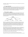
1.1 Data structures
The nature of an RPC interface is such that each RPC function takes a pointer to an argument,
which may be a scalar or a structure, and returns a pointer to a scalar or structure. It is the calling
program’s responsibility to free the memory for the returned item.
The data structures for the I/O daemon’s rpc functions are ioInfo(), ioMsg(), ioProp(), ioSts(),
ioReply(), and ioStrReply(), which are defined in io.h and derived from io.x.
Note that the data structures returned from RPC calls must be explicitly deallocate with
xdr_free(). If this were not done then a memory leak would exist.
1.1 ioInfo
The ioInfo structure is used in two of the I/O daemon’s RPC calls (iowrite_1 and ioread_1). This
structure allows a client to specify the details about which signal for which to fetch a value or set
a value.
The ioInfo structure consists of: a channel (signal number) field; a board (device number) field;
a raw flag to specify whether or not the values should be manipulated as per any scale and offset
or lookup table which may have been specified in the nirc2_io.config file (refer to section ‘’); an
ioType field which identifies the type of signal for which the value is pertinent where the type is
one of the enumerations in IO_TYPE within interface.h; a flag field which indicates whether the
value is an unsigned long or a double real; an unsigned long field which holds the value if the
flag field is set; and a double field which holds the value if the flag field is not set.
Note that the possible types are device specific. For instance, the Lakeshore temperature
controller has set points and heater values, as well as thermal inputs, and some of the DGH
modules have analog as well as digital signals.
1.2 IoMsg
The ioMsg structure is used in two of the i/o daemon RPC calls (telldevice_1 and askdevice_1).
This structure allows a client to send/receive arbitrary strings to/from an I/O device. The string is
not parsed or interpreted; hence it is the client’s responsibility to ensure a command string is
valid with respect to the remote device’s command syntax.
The ioMsg structure consists of an integer field ‘board’ which is the device number of the remote
device with which a transaction will occur and a string field ‘msg’ that hold the command or
response. Client programs must allocate the space for the string fields.
1.3
IoProp
The ioProp structure is used in the I/O daemons setioprop_1 and getioprop_1 RPC calls. This
structure allows clients to store arbitrary <name, value> strings in a hash table within the I/O
daemon. The intent is to store values which a client would later retrieve for internal used. This
concept is discussed in more detail within a subsection about ‘user variables’ within the Keyword
Library documentation (refer to subsection ).
The ioProp structure consists of two character pointer fields, namely, ‘name’ and ‘value’. The
client must allocate the space for the strings.
1.4 IoSts
The ioSts structure is returned to a client in response to finddevice_1, setioprop_1, telldevice_1,
or iowrite_1 RPC call. The intent is to return status information to a client, which issued a
command to some remote device.
The ioSts structure consists of an integer status field, which is set to 1 on success, and a string,
which holds any error message, associated with a status value other than 1.
1.5 IoStrReply
The ioStrReply structure is returned to a client in response to a getioprop_1, askdevice_1, or
getinfo_1 RPC call. All of these calls return string data to the client.
The ioStrReply structure consists of a status field, which is set to 1 when an error did not occur,
an error message string and a response message string.
1.6 IoReply
The ioReply structure is returned to a client in response to an ioread_1 RPC call. The structure
only provides for scale values.
The ioReply structure consists of: a status field which is set to 1 on success; an error message
string which is typically set when the status is not 1; a flag field which indicates whether or not
the value is returned as a double or unsigned long value; an unsigned long value field which is
set to the return value if the integer flag field is set; and a double value field which is set to the
return value if the integer flag field is not set. Note that the flag field is controlled within the
device−specific protocol routine, which, in this case, is handled within lakeshore.c or dgh.c.
1.2 Adding new I/O types
At some point in time it may be necessary to support additional types of device signals. To do so
one would need to extend the I/O type enumerations (io_type in interface.h) and then add a case
statement to the relevant functions in the device−specific modules (lakeshore.c or dgh.c). If a
new device command must be added to the keyword library then either a function must be
modified in io.c or a new function must be added to io.c.
3.2 Configuration File Format (nirc2_io.config)
When the I/O daemon initializes it reads and parses the records contained in a configuration file.
The configuration file is specified in the default script provided as a daemon command line
argument. Throughout this manual the configuration file is referred to as nirc2_io.config,
however, it is possible to change this in the default script, which one may wish to do for testing
and/or trouble−shooting.
The I/O configuration file has three functions: to identify the communications links; to identify
the devices connected to a given link; and to specify the characteristics of each of those devices.
More than one communications link may be specified but all devices and their characteristics,
for a given link, must be specified before another link is specified. That is, all device
information following a communications link is assumed to be relevant to that communications
link, up to the point that another communications link is specified.
2.1 Communications link specifications
The purpose of a communications link specification is to identify the physical port on which one
or more remote I/O devices are connected.
The devices may be connected to a host (UNIX machine) serial port, in which case the syntax
would be:
serial <port name>
Where the ’port name’ is the string as specified in the host’s device table (e.g., /dev/term/b).
Alternatively, the devices may be connected to a terminal server port, in which case the syntax
would be:
ethernet <host id> <port number>
Where ’host id’ would be the terminal server name/ip address and ’port number’ is the terminal
server port to which the remote device is connected (e.g., ethernet nirc2ts1 3003).
2.2 I/O device specification
For each I/O device connected to a communications link there must be a device specification
followed by any optional device characteristic specifications.
The syntax for the device specification is:
device=<device type> <major device number> <minor device number>
{icd=<microseconds>}
Where:
Device type for NIRC2 is any of the DGH modules (D1712, D1132, or D4172), or the
Lakeshore devices (L218S or L340).
The ’major−device number’ is the instrument−wide number (refer to section ‘’).
The ’minor−device number’ is the device address or number to which a specific device, on a
given communications link, will respond.
Icd is an inter−character delay used when writing to the communications link.
The motor daemon determines which device−specific configuration routines to call from the
device types.
If ’icd’ is not specified then characters are output in bursts and fragmentation by the UNIX
driver and/or terminal server may have an affect and, in some cases, the remote device may not
be able to keep up. In other cases the remote device may not accept delays between characters
greater than 100 milliseconds. In general the inter−character delay is very device specific and
typically requires tests to determine whether or not it is necessary. The devices on NIRC2 are set
so that data is in burst mode to the Lakeshore temperature monitors and there is a one−
millisecond inter−character delay for the Lakeshore temperature controller and all of the DGH
modules.
2.3 I/O device characteristics
A device may possess a set of characteristics, which can be specified in the configuration file.
The set of allowed characteristics depends upon the I/O module type (for NIRC2 that is the two
different Lakeshore devices and the three different DGH modules).
Each characteristic must exist on a separate line in the configuration file.
3.1
Digital signal characteristics
The syntax for the currently allowed digital I/O characteristics is:
[DIN | DOUT | DIO] = <hex bit pattern>
The DIO characteristic allows one to specify the I/O directions (input or output) of the signals,
on modules that permit such configuration. For each signal that is an output, the corresponding
bit in the bit mask must be a 1. Conversely, input signals must be designated with a 0.
The DIN and DOUT characteristics allow one to designate the active states of the digital I/O
signals. For digital inputs, the value obtained for a device is XOR’d with the mask before being
returned from the daemon. For digital outputs, the output value is exclusive ORed with the mask
before being sent to the module/device. This allows one to hide negative logic from the keyword
library and, hence, the users/clients.
3.2
Analog signal characteristics
The syntax for the currently allowed analog I/O characteristics is:
[DAC | ADC] <chan num> {scale=<real num>} {offset=<real num>}
<value pair list>
end}
{breaktable
Where: DAC or ADC, and ’chan num’ must be present; if scale is omitted then it defaults to 1.0;
if offset is omitted then it defaults to 0.0; the breaktable value pairs must each be on a separate
line and, the ordering of the pairs is keyword side followed by device side (i.e., the second value
is that which will be output to a device −DAC value− or the key for lookups on device reads
−ADC value); the breaktable ’end’ statement must be on a separate line. Note that linear
interpolation is performed on the breaktable values. As of November 2000, no break tables are
used on the NIRC2 devices.
3.3 Logging And Debugging
I/O daemon logging has been implemented with the UNIX facility syslog. The calls within the
I/O daemon are to errlog(), which actually performs the syslog calls, thereby providing some
insulation from changes in the logging mechanism.
The syslog logging level is controlled by the environment variable LOG_UPTO. This UNIX
variable must be set within the context in which the motor daemon is launched, in order to affect
syslogs from the daemon. The default logging level provides for syslogs of errors encountered in
the motor daemon. However with Solaris 5.7 this mechanism seems to function differently. As a
consequence dynamic software control of logging was added.
The tellDevice function within telldevice.c specifically checks for a command string of
“TRACE=<integer>” thereby providing a means for a user to cause the functions within
lakeshore.c to generate information other than errors.
Setting the trace level 1 or greater will cause the lakeshore functions to log a message on exit,
which will include the function’s status, and, for those that return data, the data.
If the trace level is set to a value greater than 2 then the lakeshore I/O functions (sendCmd() and
getAnswer()) will print all strings transmitted and received to standard output. If the trace level
is set to a value greater than 3 then those same functions will also generate the same information
in the log file.
There are numerous messages, which may be logged. The messages are intended to be self−
explanatory, so no attempt is made, herein, to describe the troubles that would cause a given set
of logged messages.
3.4 Support Programs
Support programs exist for the purposes of troubleshooting, integration, and I/O module setup.
These programs are intended to be used by the instrument software specialist and/or the instru−
ment specialist, but not the user community.
The support programs bypass the keyword library and interface directly to the I/O daemon via
the RPC interface.
The support programs are software modules written in the C programming language.
4.1 Askdevice
Askdevice is a standalone RPC client that allows one to issue a command string, to a specific
device, via the I/O daemon, in response to which the device will return some value. As only a
subset of the devices’ commands is programmed into the I/O daemon (refer to the DGH and
Lakeshore User’s Manuals for a description of valid commands), this function provides a client
with the ability to use various other commands.
To use askdevice one must provide an instrument−wide major−device number (refer to section
‘’) and a request string. The major device number is used, by the daemon, to locate the
communications link and device address (minor device number) of the associated physical
module/device. The device address is prepended to the request string before that string is
transmitted to the device.
The request string must be formatted in the device−specific language and syntax. Thus, one must
be familiar with the DGH and Lakeshore commands as specified in their various Users’
Manuals. The DGH and Lakeshore devices typically ignore unknown strings, which will then
result in a ’serial IO failed’ error.
If a command string is longer than a single word and/or contains non−alphanumeric characters
then it must be enclosed in double quotes.
A command string can contain embedded backslash sequences for either octal or the standard
carriage return, line feed, tab and so forth. The program will translate those sequences into their
single byte equivalents prior to sending the request to the I/O daemon.
An example to request the value of analog input channel 0 on DGH device 4 (which we assume,
for this example, is an analog input module such as D1132):
askdevice 4 RD
An example to request the value of the ADC feedback channel on a DGH analog output module
(D4172, assumed to be device 1 for this example):
askdevice 1 RAD
An example to request the device setup of device 3:
askdevice 3 RS
4.2 Telldevice
Telldevice is a standalone RPC client that allows one to issue a command string, to a specific
device, via the device daemon. As only a subset of the devices’ commands is programmed into
the I/O daemon (refer to the DGH and Lakeshore User’s Manuals for a description of valid
commands), this function provides a client with the ability to use various other commands.
To use this telldevice one must specify an instrument−wide/major−device number (refer to
section ‘’) and a request string, which must be formatted in the device specific syntax (DGH or
Lakeshore for NIRC2). The major device number is used, by the daemon, to lookup the specific
device address (minor device number) and communications link of the associated physical
device/module. The device address is prepended to the request string before that string is
transmitted to the device.
The request string is not parsed and, therefore, is assumed to be syntactically correct for the
device. Thus, one must be familiar with the DGH and Lakeshore commands as specified in their
various Users’ Manuals. The DGH and Lakeshore devices typically ignore unknown strings,
which will then result in a ’serial IO failed’ error.
If a request string is longer than a single word and/or contains non−alphanumeric characters then
it must be enclosed in double quotes.
A request string can contain embedded backslash sequences for either octal or the standard
carriage return, line feed, tab and so forth. The program will translate those sequences into their
single byte equivalents prior to sending the request to the I/O daemon.
An example to set the analog output on device 1 (assumed, for this example, to be an analog
output device D4172):
telldevice 1 AO+00010.00
An example to do a write enable (allows updates to non−volatile memory) on device 3:
telldevice 3 WE
An example to update the setup on device 3 (assumed to be a DGH analog output D4172):
telldevice 3 SU330202C4
Refer to the DGH manual for the description of the setup bits.
4.3
Showdevinfo
Showdevinfo is a standalone RPC client that allows one to request a display of the characteristics
of a specified device. The client effectively causes an RPC call within the I/O daemon.
To use this program one must specify an instrument−wide major device number, which is used,
by the daemon, to lookup the specific device address (minor device number) and
communications link. If one specifies a device number of 0 or less then the information for all
configured devices is displayed.
The display consists of: the major−device and minor−device numbers (refer to section ‘’), the i/o
type (AIN, AOUT, AIO, DIN, DOUT, DIO, or UNKNOWN), the manufacturer device type
(D1132, D4172, D1712,...); the number of digital input and output signals; and the number of
analog input and output signals.
If one specifies a number for a device, which is not configured, then "UNDEFINED" is
displayed. Similarly, "MAX=’n’" is displayed for a specified device number which is greater
than the highest numbered device configured.
3.5 Building and releasing
The building of the I/O daemon uses the Keck general make facility. This facility reduces the
amount of makefile drudgery that a programmer would otherwise need to concern him or herself
with. For a description of the make facility please refer to KSD 31 ‘/kroot Programming
Manual’.
The basic recompilation command is simply ‘gmake’. This will affect the sub tree in which the
command is issued but not the parent directories or release directories.
To recompile, link, and release the motor daemon the command is ‘gmake install’. This
command will affect the entire motor daemon sub tree (/kroot/kss/ir_common/io) as well as the
release tree.
The release tree is /kroot/rel/default/… Releasing involves adding links to the release
subdirectories of include and lib. The actual released files are written to subdirectories of
/kroot/rel/default/Versions/ioDaemon/… However, the I/O daemon executable is not built and
released from within the ir_common sub tree. The I/O daemon executable is built from
/kroot/kss/nirc2/mech/daemons. This is because there are files that exist in other directories that
must be linked into the daemon so as to tailor the daemon for the NIRC2 instrument.
Below the ioDaemon−release directory is a numeric subdirectory which corresponds to the
current release version number as specified by the ‘VERNUM’ statement in the Makefile within
/kroot/kss/ir_common/io. If a software specialist modifies any of the C modules used by the
ioDaemon then that person is expected to change the VERNUM statement. Doing this will
preserve the current released files so reverting can easily be accomplished. If VERNUM is not
changed then the current release files will be overwritten when ‘gmake install’ processes.
The software specialist is also expected to commit any changes with the appropriate CVS
commands (refer to alternate documentation for CVS commands), including the modified
Makefile.
Note that the files within /kroot/kss/ir_common and the subdirectory util must also be rebuilt
upon occasion. This is done via a ‘gmake install’ within ir_common.
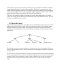
4
Keyword Library
Control of the NIRC2 mechanisms and I/O devices is provided by the standard Keck tasking
library (KTL) keywords and the associated show, xshow, and modify programs. More
sophisticated clients can be constructed in which case they would need to interface to KTL via
the functions contained in software modules such as ktcl and kidl. The UCLA graphical user
interface uses kidl to interface to the detector system and various other NIRC2 GUIs use ktcl
(the status window interfaces to the detector keyword library as well as the mechanisms keyword
library).
A complete description of KTL can be found in KSD 28, however, a brief overview follows.
KTL consists of a set of routines, which interface to various control systems by locating
shareable libraries that are tailored for those systems. The functions in the libraries must
implement a generic set of routines, which serve as the interface between KTL and the
independent systems. The generic routines are analogous to the device drivers on most modern
operating systems, namely, keyword_open(), keyword_ioctl(), keyword_read(),
keyword_write(), and keyword_close(). Those systems, which need to provide asynchronous
updates, must also implement keyword_event () and keyword_respond().
The link between a shareable library and a specific control system is provided by the ‘service’
name, which is typically an acronym for the control system. This constrains the spellings of the
shareable libraries to be of the form lib<service>_<text>.so.0.0. For instance, the NIRC2
mechanism keyword library is libnirc2_keyword.so.0.0 and the NIRC2 detector keyword library
is libalad_keyword.so.0.0 (where the acronym is for Aladdin).
When a client calls keyword_open() the actual processing is specific to the requirements of the
control system for which the library was created. The NIRC2 detector system software consists
of an RPC server, which possesses the knowledge of all the detector keywords, hence the
keyword library functions simply make RPC calls to that server (refer to the UCLA detector
documents). The NIRC2 mechanism software consists of two RPC daemons (as described in
previous sections) but those daemons are essentially communications agents and the keyword
knowledge is contained within the functions of the keyword library.
The phrase ‘NIRC2 keyword library’ will refer to the NIRC2 mechanism keyword library, unless
explicitly stated otherwise, in the remainder of this section.
Many keyword libraries have the details of their keywords implemented as static structures in a
list. The NIRC2 keyword library builds it’s keyword table from configuration files (refer to
sections ‘’), which are read when a client invokes keyword_open(). The configuration files can
be dynamically modified, although it is expected that an instrument specialists will rarely do
modifications on those files. When one of the keyword programs is used, the KTL layer causes
the keyword library (libnirc2_keyword.so.0) to be instantiated. In the case of show and modify,
the keyword library terminates when the requested action is complete. In the case of xshow, the
library persists until xshow is terminated.
When the one−shot utilities (show and modify) are invoked the NIRC2 keyword library
configures itself, processes the command, and terminates. Thus there is no persistence, within
the keyword library, between keyword commands. Any persistence is a function of the daemons
and the functions in the keyword library may extensive use of the hash tables maintained by the
daemon. Thus, the keyword library is essentially a conduit for translating mechanism specifics
into device specifics.
The keyword library can be conceptualized as two layers each layer of which could have its own
set of keywords.
A low−level layer of keywords provides an interface to the mechanisms that is more or less
device specific. For instance motor control keywords would allow one to move a motor to a
specified position but would not provide feedback during that move, a sort of fire−and−forget
control mode. This layer of control would not understand that a given mechanism was a wheel or
slider stage but simply that a motor is associated with the keyword for which a set of operations
exists. For this level of control the functions in the files (analogKeyword.c, digitalKeyword.c,
ioKeyword.c, and motorKeyword.c) within /kroot/kss/ir_common/keyword, utilize the functions
contained in motor.c and io.c to interface with the motor and I/O daemon tasks (refer to sections
and ).
A higher−level layer of keywords provides an interface to the mechanisms that is more of a
logical device level. The associated keywords use the functions in the files (mechanisms.c,
wheels.c, and sliders.c) within /kroot/kss/nirc2/mech/keyword to utilize the functions within
motor.c and io.c to interface with the motor and I/O daemon tasks. The higher−level functions
understand that a given mechanism is either a wheel or slider stage and implement algorithms
pertinent to the type of the mechanism.
The distinction between the two levels of keywords is provided within the keyword
configuration file (nirc2_config_file).
The keywords can be categorized as mechanism keywords, motor keywords, I/O keywords, and
user keyword. Each of these categories is described in subsequent subsections.
4.1 Mechanism keywords
The mechanism keywords refer to the keywords, which are associated with the NIRC2 motor
controlled mechanisms that have a higher−level abstraction than simply a motor. There is a set
of keywords associated with each of the NIRC2 cryogenic mechanisms. The exact set of
keywords that exists is provided by a configuration file (refer to section ‘’).
1.1 Keyword naming conventions
In general the mechanism keywords consists of a prefix and a suffix, such that the prefix is tied
to a specific mechanism via a configuration file, and the suffix is essentially a logical command
or logical operation to be performed on the mechanism.
The prefixes are used by the keyword library functions to find the mechanisms’ characteristics
that are read from the relevant configuration files when the keyword library is invoked, and to
determine which mechanisms’ functions to invoke (wheels.c or sliders.c).
The keyword suffixes are used by the keyword library functions to determine which specific
functions within wheels.c and sliders.c to invoke. The invoked functions then drive the relevant
motors as per the functionality implied by the suffix (logical operation). The associations
between the keyword suffixes and logical operations are provided by hard−coded lists
(WheelTable and SliderTable) within wheels.c and sliders.c. The contents of these tables are
entered into hash tables when the keyword library is invoked such that subsequent read and/or
write requests, for the suffixes, will efficiently find the necessary C functions to call.
Restrictions in the spelling of mechanism keywords exist as there must be some relation between
a keyword and the desired function commanded of a specific mechanism. The prefixes are
restricted in spelling to those specified in nirc2_mechanism.config (refer to section ‘’) and the
suffixes are restricted to the spellings within the aforementioned WheelTable and SliderTable
lists. Note that the spelling of some keywords is a little cryptic. This was done for those
keywords that one might want included in a fits header, as fits header keywords are restricted to
a maximum of eight characters.
As there are eleven motor controller mechanisms, on the NIRC2 instrument, there are eleven
mechanism keyword prefixes: CAM for the camera slide; GRS for the grism slider; SHR for the
shutter whose type is designated as a slider; FWI for the inner filter wheel; FWO for the outer
filter wheel; PMS for the pupil mask selector wheel; PMR for the pupil mask rotator (keywords
exist for this only for integration and testing as it is implemented differently for the other
mechanisms as specified in section ‘’); SLS for the slit slider; SLM for the slit mask slider; PSI
for the inner preslit slider; and PSO for the outer preslit slider.
1.2 Mechanism keyword types
Two major types of mechanism keywords exist: wheel mechanism keywords which are
associated with mechanisms that are rotated to discrete positions, and slider mechanism
keywords which are associated with mechanisms that are linearly translated to discrete positions.
Note that the pupil mask rotator keywords are not included with the mechanism keywords (the
pupil mask rotator is expounded upon in section ‘’).
The depiction of whether a mechanism is a wheel or a slider is specified in both of the keyword
library configuration files (refer to section ) and is referred to as the keyword type. The keyword
type is retained within the data structures that are constructed within wheels.c and sliders.c when
the configurations files are read upon keyword library startup.
Another small category of keywords exists which is composed of a few miscellaneous keywords,
which are not associated with specific mechanisms. These keywords are essentially hard−coded
within the C modules and are not a composite of a prefixes and suffixes.
1.3 Mechanism operations relating to keyword suffixes
There are numerous operations that can be performed on the instrument mechanisms. Most of
those operations are identical or at least analogous between the wheel and slider mechanisms.
One exception to this is the suffix relating to the mechanisms’ positions, in engineering units, as
the wheels’ positions are expressed as angular measures in degrees and the sliders’ positions are
expressed as displacements in millimeters. Consequently, the keyword suffixes, for these
measures, differ between wheel and slider mechanisms.
Some of the mechanism operations imply read only mechanism keywords and vis−à−vis others
imply write only. For instance, FWOSTAT would be a read only keyword, which provides the
current motion state of the outer filter wheel, whereas FWOSTOP would be a write only
keyword, which would cause the outer filter wheel to stop its current motion.
The keyword suffixes provide a logical set of operations that a client is permitted to perform on
the instrument mechanisms. To cause an operation to happen the functions within mechanisms.c,
sliders.c, and wheels.c are invoked. These functions, in turn, invoke functions within motor.c to
interface with the motor daemon, which handles the command transactions with the motors.
Each of the keyword suffixes is discussed in detail within the following subsections. The C
functions calling sequence, for reading and writing of each of the keywords that are constructed
from the suffixes, are include with the suffix descriptions.
3.1 ACCEL
The ACCEL suffix refers to a mechanism’s motor acceleration parameter. As of November 2000
this is a write only operation.
Note that the non−operational keywords of this type may be removed from the default
configuration file nirc2_config_file at some point.
Writing to an acceleration keyword will invoke either sliderDynamics() within sliders.c or
wheelDynamics() within wheels.c, as per the keyword type, which is implied by the keyword
prefix. The complete calling sequences follow.
Keyword library calling sequence:
keyword_write (keyword.c)
sliderDynamics or wheelDynamics (sliders.c or wheels.c)
motorSetAcceleration −> motorCmd
(motor.c)
motorcmd_1 (motor_clnt.c RPC)
Motor daemon calling sequence:
motorcmd_1 (clientFuncs.c)
animaticsCmd −> sendCommand (animatics.c)
3.2 ACTIVE
The ACTIVE suffix refers to a mechanism’s current/impending motion state.
When a function is called which will cause a mechanism to move, whether from a homing,
absolute position, or delta position command, the motion control function will set and store an
active flag for that mechanism. This is done even before the motion commands are issued to the
relevant motor. Note that the C code does not clear the active flag, as clearing the flag is the
responsibility of the client programs.
This functionality was added during motor repeatability tests so that scripts could initiate parallel
motor moves and then determine when all such moves commenced before proceeding to the next
step in the script. Of course those scripts would have to reset all the active flags.
Note that the active flags are analogous to ‘user keywords’, as described in section , because their
values are stored in a hash table within the motor daemon.
The calling sequences for reading an ACTIVE keyword follows.
Keyword library calling sequence:
keyword_read (keyword.c)
sliderRequest or wheelRequest (sliders.c or wheels.c)
getMotorProp(motor.c)
getmotorprop_1 (motor_clnt.c RPC)
Motor daemon calling sequence:
getmotorprop_1 (clientFuncs.c)
propGetString (properties.c)
The calling sequences for writing an ACTIVE keyword follows.
Keyword library calling sequence:
keyword_write (keyword.c)
sliderCommand or wheelCommand (sliders.c or wheels.c)
setMotorProp (motor.c)
setmotorprop_1 (motor_clnt.c RPC)
Motor daemon calling sequence:
setmotorprop_1 (clientFuncs.c)
propSetString (properties.c)
3.3 AMPS
The AMPS suffix refers to a mechanism’s maximum motor current parameter. As of November
2000 this is a write only operation. This keyword has aliases that are: CURRENT, and CRNT.
As of the aforementioned date only the AMPS suffix is used in the configuration file.
Note that the non−operational keywords of this type may be removed from the default
configuration file nirc2_config_file at some point.
Writing to an amperage keyword will invoke either sliderDynamics() within sliders.c or
wheelDynamics within wheels.c, as per the keyword type, which is implied by the keyword,
prefix. The calling sequences for writing an AMPS keyword follow.
Keyword library calling sequence:
keyword_write (keyword.c)
sliderCommand or wheelCommand (sliders.c or wheels.c)
motorSetCurrent −> motorCmd (motor.c)
motorcmd_1 (motor_clnt.c RPC)
Motor daemon calling sequence:
motorcmd_1 (clientFuncs.c)
animaticsCmd −> sendCommand (animatics.c)
3.4 BLASH
The BLASH suffix refers to a mechanism’s backlash offset. As of November 2000 this is a write
only operation. This keyword has the alias BACKL but as of the aforementioned date only the
BLASH suffix is used in the configuration file.
The backlash offset is applied within the motor controllers’ subroutines for motor moves (refer
to section ‘’). Although this parameter is dynamically modifiable the intent is that once
instrumentation integration is complete that this parameter will seldom if ever be changed.
Note that the non−operational keywords of this type may be removed from the default
configuration file nirc2_config_file at some point.
Writing to a backlash keyword will invoke either sliderDynamics() within sliders.c or
wheelDynamics within wheels.c, as per the keyword type, which is implied by the keyword,
prefix. The calling sequences for writing a backlash keyword follow.
Keyword library calling sequence:
keyword_write (keyword.c)
sliderCommand or wheelCommand (sliders.c or wheels.c)
motorSetBackLash −> motorCmd (motor.c)
motorcmd_1 (motor_clnt.c RPC)
Motor daemon calling sequence:
motorcmd_1 (clientFuncs.c)
animaticsCmd −> sendCommand (animatics.c)
3.5 BRAKES
The BRAKES suffix refers to a mechanism’s brakes. Under normal operations the brakes are
automatically released and set, at the appropriate times, by the motor controller subroutines
(refer to section ‘’). However this functionality is provided for trouble−shooting mechanism
problems. Specifically the BRAKES keywords, in conjunction with the ENABLE keywords,
would allow one to ‘free−wheel’ a mechanism.
Note that the non−operational keywords of this type may be removed from the default
configuration file nirc2_config_file at some point.
Writing to a backlash keyword will invoke either sliderDynamics() within sliders.c or
wheelDynamics within wheels.c, as per the keyword type, which is implied by the keyword,
prefix. The calling sequences for writing a BRAKES keyword follow.
Keyword library calling sequence:
keyword_write (keyword.c)
sliderCommand or wheelCommand (sliders.c or wheels.c)
motorBrakes −> motorCmd (motor.c)
motorcmd_1 (motor_clnt.c RPC)
Motor daemon calling sequence:
motorcmd_1 (clientFuncs.c)
animaticsCmd −> sendCommand (animatics.c)
3.6 DELTA
The DELTA suffix refers to moving a mechanism a relative distance from its current position.
This suffix has an alias of DEL, which is not used, in the configuration file of as November
2000.
The composite keywords can be written. When written to the keywords will typically initiate
motor motion and will cause the keywords with suffixes TARG and DEST to be updated (refer
to sections and ).
The displacement keywords are write only keywords which will invoke either moveSliderCmd()
within sliders.c or moveWheelCmd() within wheels.c, as per the keyword type which is implied
by the keyword prefix. The calling sequences for writing displacement keywords follow.
Keyword library calling sequence:
keyword_write (keyword.c)
moveSliderCmd or moveWheelCmd −> moveSlider or moveWheel (sliders.c or
wheels.c)
motorMove −> motorCmd (motor.c)
motorcmd_1 (motor_clnt.c RPC)
Motor daemon calling sequence:
motorcmd_1 (clientFuncs.c)
animaticsCmd −> sendCommand (animatics.c)
3.7 DESCR
The DESCR suffix provides clients the ability to obtain a descriptive string for a given
mechanism. The descriptions are those specified in nirc2_mechanism.config (refer to section ).
The intent is to provide information for user interfaces.
The DESCR keywords are read only keywords which cause either the sliderInfoFn() function or
the wheelInfoFn() function, within sliders.c and wheels.c, to be invoked as per the mechanism
type. The complete calling sequences follow.
Keyword library calling sequence:
keyword_read (keyword.c)
sliderInfoFn or wheelInfoFn (sliders.c or wheels.c)
3.8
DEST
The DEST suffix provides clients read only keywords, which specify the raw encoder positions
to which mechanisms were last commanded to acquire.
The destination keywords are analogous to ‘user keywords’ (refer to section ) in that their values
are retained in a hash table within the motor daemon.
The destination keywords are updated whenever mechanism motion keywords are written.
Reading a destination keyword causes either the sliderRequest() function or the wheelRequest()
function, within sliders.c and wheels.c, to be invoked as per the mechanism type. The read
calling sequences follow.
Keyword library calling sequence:
keyword_read (keyword.c)
sliderRequest or wheelRequest (sliders.c or wheels.c)
getMotorProp(motor.c)
getmotorprop_1 (motor_clnt.c RPC)
Motor daemon calling sequence:
getmotorprop_1 (clientFuncs.c)
propGetString (properties.c)
3.9 DIST or ANGL
The DIST and ANGL suffixes refer to mechanisms positions in engineering units. For wheel
mechanisms the angular measure is in degrees and for slider mechanisms the distance measure is
in millimeters. The values are relative to mechanisms’ home locations.
The composite keywords can be read and written. When written to the keywords will typically
initiate motor motion and will cause the keywords with suffixes TARG and DEST to be updated
(refer to sections and ). However, once motor motion commences, reading these keywords will
provide values that reflect the mechanisms’ current positions and not the values to which they
were set. Thus, as the motors move, the keywords will be continually changing until motor
motion stops, which, if the positions are successfully attained, will then have values agreeing
with the TARG keywords and be consistent with the values to which the keywords were
originally written.
Writing the position keywords will cause either the moveSliderCmd() function or the
moveWheelCmd() function to be invoked. The write calling sequences follow.
Keyword library calling sequence:
keyword_write (keyword.c)
moveSliderCmd or moveWheelCmd −> moveSlider or moveWheel (sliders.c or
wheels.c)
motorMove −> motorCmd (motor.c)
motorcmd_1 (motor_clnt.c RPC)
Motor daemon calling sequence:
motorcmd_1 (clientFuncs.c)
animaticsCmd −> sendCommand (animatics.c)
The read calling sequences follow.
Keyword library calling sequence:
keyword_read (keyword.c)
sliderPositionSts or wheelPositionSts −> updatePosnFeedback (sliders.c or wheels.c)
motorTellPosition −> motorSts (motor.c)
motorsts_1 (motor_clnt.c RPC)
Motor daemon calling sequence:
motorsts_1 (clientFuncs.c)
animaticsSts (animatics.c)
intRequest (connectFuncs.c)
procAnimaticsCmd −> sendCommand and getAnswer (animatics.c)
3.10 ENABLE
The ENABLE suffix provides composite mechanism keywords, which allow clients to enable
and disable the mechanisms’ motor servos (vis−à−vis motor power or holding torque).
Under normal operations the motor servos are automatically enabled and disabled, at the
appropriate times, by the motor controller subroutines (refer to section ‘’). However this
functionality is provided for trouble−shooting mechanism problems. Specifically the ENABLE
keywords, in conjunction with the BRAKE keywords, would allow one to ‘free−wheel’ a
mechanism.
Note that the non−operational keywords of this type may be removed from the default
configuration file nirc2_config_file at some point.
The ENABLE keywords are write only and cause either the sliderCommand() or the
wheelCommand() functions, within sliders.c and wheels.c, to be invoked as per the mechanism
type. The write calling sequences follow.
Keyword library calling sequence:
keyword_write (keyword.c)
sliderCommand or wheelCommand (sliders.c or wheels.c)
motorPower −> motorCmd (motor.c)
motorcmd_1 (motor_clnt.c RPC)
Motor daemon calling sequence:
motorcmd_1 (clientFuncs.c)
animaticsCmd −> sendCommand (animatics.c)
3.11 HOME
The HOME suffix provides for mechanism keywords, which will cause mechanisms to find their
‘home’ positions and to provide feedback as to whether or not the mechanisms have been homed
since their last software resets or power cycles.
The Animatics Smartmotors do not provide homing commands or statuses so, on NIRC2, the
functionality is provided by homing subroutines, which are downloaded into the motor
controllers’ non−volatile memories (refer to section ‘’). At the end of the homing subroutines a
motor controller variable is set to indicate that homing is complete. It is the value of the internal
motor controller variable that is returned when a HOME keyword is read. Note that all motor
controller variables default to 0 upon a software reset or power cycle.
Whereas writing a HOME keyword will invoke either the homeSliderCmd() function or the
homeWheelCmd() function within the same C modules. The write calling sequences follow.
Keyword library calling sequence:
keyword_write (keyword.c)
homeSliderCmd or homeWheelCmd −> homeSlider or homeWheel (sliders.c or
wheels.c)
motorHome −> motorCmd (motor.c)
motorcmd_1 (motor_clnt.c RPC)
Motor daemon calling sequence:
motorcmd_1 (clientFuncs.c)
animaticsCmd −> sendCommand (animatics.c)
When a HOME keyword is read either the sliderHomeSts() function or the wheelHomeSts()
function, within sliders.c and wheels.c, is invoked as per the mechanism type. The read calling
sequences follow.
Keyword library calling sequence:
keyword_read (keyword.c)
sliderHomeSts or wheelHomeSts (sliders.c or wheels.c)
motorTellHomingPosition −> motorSts (motor.c)
motorsts_1 (motor_clnt.c RPC)
Motor daemon calling sequence:
motorsts_1 (clientFuncs.c)
animaticsSts (animatics.c)
intRequest (connectFuncs.c)
procAnimaticsCmd −> sendCommand and getAnswer (animatics.c)
3.12 IDLE
The IDLE suffix provides for mechanism keywords, which will provide clients with the current
idle status of the associate motor where idleness means that the motor is not currently moving
The Animatics Smartmotors do not provide for status commands that would explicitly indicate
whether or not a motor is idle. On NIRC2 this was implemented by always setting an specific
motor controller variable prior to executing a motor controller subroutine –the subroutines are
downloaded into the motor controllers’ non−volatile memories− and those subroutines always
clear that variable just before exiting. In this way the motor controllers’ variables can be read to
determine whether or not they are 0 and, hence whether or not the controller is idle.
The IDLE keywords are read only and cause either the sliderIdleSts() function or the
wheelIdleSts() function, within sliders.c and wheels.c, to be invoked. The read calling sequences
follow.
Keyword library calling sequence:
keyword_read (keyword.c)
sliderIdleSts or wheelIdleSts (sliders.c or wheels.c)
motorIsIdle −> motorSts (motor.c)
motorsts_1 (motor_clnt.c RPC)
Motor daemon calling sequence:
motorsts_1 (clientFuncs.c)
animaticsSts (animatics.c)
intRequest (connectFuncs.c)
procAnimaticsCmd −> sendCommand and getAnswer (animatics.c)
3.13 INFO
The INFO suffix allows mechanism keywords to provide clients with mechanism−specific
information, which was previously loaded from configuration files (refer to section ). The intent
is to provide users with names and position information for when they have memory lapses, of
course the information could also be parsed by user interfaces so that they can self configure
themselves.
The information provided consists of: the mechanism’s associated motor number, encoder
resolution, and number of discrete positions; for each discrete position the position name,
number, position value in engineering units, positioning accuracy, and absolute encoder position
are provided.
The INFO keywords are all read only and invoke either the sliderShowInfo() function or the
wheelShowInfo() function, within sliders.c and wheels.c, as per the mechanism type. The calling
sequences follow.
Keyword library calling sequence:
keyword_read (keyword.c)
sliderShowInfo or wheelShowInfo (sliders.c or wheels.c)
3.14 INIT
The INIT suffix provides for mechanism keywords to either initialize mechanisms and/or
provide feedback on whether or not mechanisms have been initialized since they last
experienced a software reset or power cycle.
The Animatics Smartmotors default to a set of motor control parameter values, which do not
permit the motors to be moved. To alleviate this an initialization subroutine was downloaded
into each of the motor controller’s non−volatile memory. The subroutines set the motor control
parameters to safe values, which will allow the motors to be moved albeit not necessarily at their
optimums. The INIT keywords cause the initialization subroutines to be executed.
At the end of the initialization subroutines, motor controller variables are set to indicate that
initialization has been performed. It is the values of the internal motor control variables that are
returned when INIT keywords are read.
Writing an INIT keyword will invoke either the sliderCommand() function or the
wheelCommand() function within sliders.c or wheels.c. as per the mechanism type. The calling
sequences follow.
Keyword library calling sequence:
keyword_write (keyword.c)
sliderCommand or wheelCommand (sliders.c or wheels.c)
motorInitialize −> motorCmd (motor.c)
motorcmd_1 (motor_clnt.c RPC)
Motor daemon calling sequence:
motorcmd_1 (clientFuncs.c)
animaticsCmd −> sendCommand (animatics.c)
When an INIT keyword is read either the sliderRequest() function or the wheelRequest()
function, within sliders.c and wheels.c, is invoked as per the mechanism type. The calling
sequences follow.
Keyword library calling sequence:
keyword_read (keyword.c)
sliderRequest or wheelRequest (sliders.c or wheels.c)
motorTellInitSts −> motorSts (motor.c)
motorsts_1 (motor_clnt.c RPC)
Motor daemon calling sequence:
motorsts_1 (clientFuncs.c)
animaticsSts (animatics.c)
intRequest (connectFuncs.c)
procAnimaticsCmd −> sendCommand and getAnswer (animatics.c)
3.15 KILL
The KILL suffix provides for keywords to abruptly stop mechanisms’ motors.
In practice these keywords do not behave as expected. All motor motions are performed by
invoking subroutines which are stored in the motor controllers’ non−volatile memories, in most
cases, the subroutines perform two moves so as to compensate for backlash, and there is no
mechanism for terminating a subroutine that is executing, short of a software reset. As a result a
KILL will usually occur before the backlash move thus only the ‘slew’ will be killed and the
backlash move will still occur.
If a true kill is needed then the user should cause a software reset to occur (refer to section ).
The KILL keywords are write only and invoke either the sliderCommand() function or the
wheelCommand() function, within sliders.c and wheels.c, as per the mechanism type. The
calling sequences follow.
Keyword library calling sequence:
keyword_write (keyword.c)
sliderCommand or wheelCommand(sliders.c or wheels.c)
killMechanism (mechanisms.c)
motorKill −> motorCmd (motor.c)
motorcmd_1 (motor_clnt.c RPC)
Motor daemon calling sequence:
motorcmd_1 (clientFuncs.c)
animaticsCmd −> sendCommand (animatics.c)
3.16 LMTORIDE
The LMTORIDE suffix provides keywords for over−riding a mechanism’s software limits. This
would typically not be done during normal operations but is often useful when trouble−shooting
are calibrating after a mechanism has been physically altered.
Note that the non−operational keywords of this type may be removed from the default
configuration file nirc2_config_file at some point.
Writing a limit override keyword will invoke either the sliderCommand() function or the
wheelCommand() function within sliders.c or wheels.c, as per the mechanism’s type. The write
calling sequences follow.
Keyword library calling sequence:
keyword_write (keyword.c)
sliderCommand or wheelCommand (sliders.c or wheels.c)
setMotorProp (motor.c)
setmotorprop_1 (motor_clnt.c RPC)
Motor daemon calling sequence:
setmotorprop_1 (clientFuncs.c)
propSetString (properties.c)
Reading a LMTORIDE keyword will invoke either the sliderRequest() function or the
wheelRequest() function, within sliders.c and wheels.c, as per the mechanism type. The read
calling sequences follow.
Keyword library calling sequence:
keyword_read (keyword.c)
sliderRequest or wheelRequest (sliders.c or wheels.c)
getMotorProp(motor.c)
getmotorprop_1 (motor_clnt.c RPC)
Motor daemon calling sequence:
getmotorprop_1 (clientFuncs.c)
propGetString (properties.c)
3.17 MAXPE
The MAXPE suffix allows keywords to control a mechanism’s maximum allowed position error.
When a maximum position error value is exceeded a motor will stall.
Note that the non−operational keywords of this type may be removed from the default
configuration file nirc2_config_file at some point.
As of November 2000 the MAXPE keywords are write only and invoke either the
sliderDynamics() function or the wheelDynamics() function, within sliders.c and wheels.c, as
per the mechanism type. The write calling sequences follow.
Keyword library calling sequence:
keyword_write (keyword.c)
sliderDynamics or wheelDynamics (sliders.c or wheels.c)
motorSetAcceleration −> motorCmd
(motor.c)
motorcmd_1 (motor_clnt.c RPC)
Motor daemon calling sequence:
motorcmd_1 (clientFuncs.c)
animaticsCmd −> sendCommand (animatics.c)
3.18 MAXPOS
The MAXPOS suffix provides for keywords to obtain the maximum position to which a
mechanism can be commanded. The maximum positions are retained in the motor daemon and
are read from a configuration file (refer to section ).
The MAXPOS keywords are read only and invoke either the sliderRequest() function or the
wheelRequest() function, within sliders.c and wheels.c, as per the mechanism type. The read
calling sequence follows.
Keyword library calling sequence:
keyword_read (keyword.c)
sliderRequest or wheelRequest (sliders.c or wheels.c)
3.19 MINPOS
The MINPOS suffix provides for keywords to obtain the minimum position to which a
mechanism can be commanded. The minimum positions are retained in the motor daemon and
are read from a configuration file (refer to section ).
The MINPOS keywords are read only and invoke either the sliderRequest() function or the
wheelRequest() function, within sliders.c and wheels.c, as per the mechanism type. The read
calling sequence follows.
Keyword library calling sequence:
keyword_read (keyword.c)
sliderRequest or wheelRequest (sliders.c or wheels.c)
3.20 MTR
The MTR suffix provides for keywords to return the mechanisms’ associated motor numbers.
In actual fact the MTR keywords can be written to so as to change the number of a motor
associated with a mechanism. This is a potentially dangerous thing to do! One may wish to do
this to recover from a severe motor failure where a motor is swapped with a faulty one so as to
provide some instrument functionality at the expense of some other functionality, or if a spare
motor or motor memory is swapped with a faulty one on the instrument. In both these cases the
motor number may not be the same as the original in which case the MTR keywords would
become useful. In all probability the MTR keywords will not exist in the default keyword
configuration file and will only exist in an engineering mode.
Writing a Mtr keyword will invoke either the sliderCommand() function or the
wheelCommand() function within those same C modules. The write calling sequence follows.
Keyword library calling sequence:
keyword_write(keyword.c)
sliderCommand or wheelCommand (sliders.c or wheels.c)
Reading a MTR keyword will invoke either the sliderRequest() function or the wheelRequest()
function, within sliders.c and wheels.c, as per the mechanism type.
Keyword library calling sequence:
keyword_read (keyword.c)
sliderRequest or wheelRequest (sliders.c or wheels.c)
3.21 NAME
The NAME suffix provides for keywords to drive mechanisms to positions that are specified by
names that are read from configuration files (refer to sections ‘’ and ‘’) or to provide feedback
about the mechanisms’ current positions.
A mechanism’s position names, ordinal position numbers, angular or distance positions, and
encoder positions are all specified in the mechanism−details files. When a mechanism is moved
via the setting of its NAME keyword, the corresponding encoder position is derived and the
associated motor is commanded to that position. If an unknown name is specified then the motor
is not moved and an error is returned.
The writing of a NAME keyword will cause the corresponding TARG, TRGT, and DEST
keywords to be updated (refer to sections , , and ) and motor motion to be initiated. Once motor
motion commences, reading a NAME keyword will provide values that reflect the mechanism’s
current position and not the values to which the NAME keyword was set. Thus, as the motor
moves, the NAME keyword (as well as other motion feedback keywords) will be continually
changing until motor motion stops. Assuming that the position is successfully attained, then the
NAME keyword will again agree with the TARG keyword. As implied above, when a
mechanism’s NAME keyword is read, the current motor position is obtained from the motor and
compared with the encoder positions associated with the position names. If a motor position does
not correspond with a named position then ‘Unknown’ is returned.
When a NAME keyword is written, either the moveSliderCmd() function or the
moveWheelCmd() function, within sliders.c and wheels.c, is invoked as per the mechanism type.
The write calling sequences follow.
Keyword library calling sequence:
keyword_write (keyword.c)
moveSliderCmd or moveWheelCmd −> moveSlider or moveWheel (sliders.c or
wheels.c)
motorMove −> motorCmd (motor.c)
motorcmd_1 (motor_clnt.c RPC)
Motor daemon calling sequence:
motorcmd_1 (clientFuncs.c)
animaticsCmd −> sendCommand (animatics.c)
When a NAME keyword is read, either the sliderPositionSts() function or the wheelPositionSts()
function is invoked. The read calling sequences follow.
Keyword library calling sequence:
keyword_read (keyword.c)
sliderPositionSts or wheelPositionSts −> updatePosnFeedback (sliders.c or wheels.c)
motorTellPosition −> motorSts (motor.c)
motorsts_1 (motor_clnt.c RPC)
Motor daemon calling sequence:
motorsts_1 (clientFuncs.c)
animaticsSts (animatics.c)
intRequest (connectFuncs.c)
procAnimaticsCmd −> sendCommand and getAnswer (animatics.c)
3.22 NUM
The NUM suffix provides for keywords to either move a mechanism to an ordinal position or to
provide feedback about a mechanism’s current position.
A mechanism’s position names, ordinal position numbers, angular or distance positions, and
encoder positions are all specified in the mechanism−specific configuration files (refer to
sections ‘’ and ‘’). When a mechanism is moved via the setting of its NUM keyword, the
corresponding encoder position is derived and the associated motor is commanded to that
position. If an out−of−range position number is specified then the motor is not moved and an
error is returned.
Writing to a NUM keyword, with an in−range value, will initiate motor motion. Once motor
motion commences, reading the NUM keyword will provide values that reflect the mechanism’s
current position and not the values to which the keyword was set. Thus, as the motors move, the
NUM keyword will be continually changing until motor motion stops, such that most of the time
the NUM keyword will have a value of –1 as it will be between discrete positions.
As implied above, when a mechanism’s NUM keyword is read, the current motor position is
obtained from the motor and compared with the encoder positions associated with the ordinal
position numbers. If a motor position does not correspond with an ordinal position number then
−1 is returned.
When a NUM keyword is written, either the moveSliderCmd() function or the
moveWheelCmd() function, within sliders.c and wheels.c, is invoked as per the mechanism type.
The write calling sequences follow.
Keyword library calling sequence:
keyword_write (keyword.c)
moveSliderCmd or moveWheelCmd −> moveSlider or moveWheel (sliders.c or
wheels.c)
motorMove −> motorCmd (motor.c)
motorcmd_1 (motor_clnt.c RPC)
Motor daemon calling sequence:
motorcmd_1 (clientFuncs.c)
animaticsCmd −> sendCommand (animatics.c)
When a NUM keyword is read, either the sliderPositionSts() function or the wheelPositionSts()
function is invoked. The read calling sequences follow.
Keyword library calling sequence:
keyword_read (keyword.c)
sliderPositionSts or wheelPositionSts −> updatePosnFeedback (sliders.c or wheels.c)
motorTellPosition −> motorSts (motor.c)
motorsts_1 (motor_clnt.c RPC)
Motor daemon calling sequence:
motorsts_1 (clientFuncs.c)
animaticsSts (animatics.c)
intRequest (connectFuncs.c)
procAnimaticsCmd −> sendCommand and getAnswer (animatics.c)
3.23 RAW
The RAW suffix provides for keywords to move mechanisms to absolute encoder positions
and/or provide feedback as to the mechanisms’ current encoder positions.
The writing of a RAW keyword will cause the corresponding TARG and DEST keywords to be
updated (refer to sections and ) and motor motion to be initiated. Once motor motion
commences, reading a RAW keyword will provide values that reflect the mechanism’s current
position and not the values to which the RAW keyword was set. Thus, as the motor moves, the
RAW keyword (as well as other motion feedback keywords) will be continually changing until
motor motion stops. Assuming that the position is successfully attained, then the RAW keyword
will again agree with the DEST keyword.
As implied above, when a mechanism’s RAW keyword is read, the current motor position is
obtained from the motor and compared with the encoder positions associated with the position
names.
When a RAW keyword is written, either the moveSliderCmd() function or the
moveWheelCmd() function, within sliders.c and wheels.c, is invoked as per the mechanism type.
The write calling sequences follow.
Keyword library calling sequence:
keyword_write (keyword.c)
moveSliderCmd or moveWheelCmd −> moveSlider or moveWheel (sliders.c or
wheels.c)
motorMove −> motorCmd (motor.c)
motorcmd_1 (motor_clnt.c RPC)
Motor daemon calling sequence:
motorcmd_1 (clientFuncs.c)
animaticsCmd −> sendCommand (animatics.c)
When a RAW keyword is read, either the sliderPositionSts() function or the wheelPositionSts()
function is invoked. The read calling sequences follow.
Keyword library calling sequence:
keyword_read (keyword.c)
sliderPositionSts or wheelPositionSts −> updatePosnFeedback (sliders.c or wheels.c)
motorTellPosition −> motorSts (motor.c)
motorsts_1 (motor_clnt.c RPC)
Motor daemon calling sequence:
motorsts_1 (clientFuncs.c)
animaticsSts (animatics.c)
intRequest (connectFuncs.c)
procAnimaticsCmd −> sendCommand and getAnswer (animatics.c)
3.24 RDY
The RDY suffix provides for keywords which indicate whether or not a mechanism is in a ready
state, where that state is defined to be true when the current motor position agrees with the last
demanded motor position and the motor is idle.
The RDY keywords are read only and invoke either sliderRequest() or wheelRequest(), within
sliders.c and wheels.c, as per the mechanism type. The calling sequences follow.
Keyword library calling sequence:
keyword_read (keyword.c)
sliderRequest or wheelRequest (sliders.c or wheels.c)
getMotorProp(motor.c)
getmotorprop_1 (motor_clnt.c RPC)
Motor daemon calling sequence:
getmotorprop_1 (clientFuncs.c)
propGetString (properties.c)
3.25 RESET
The RESET suffix provides for keywords to perform software resets on mechanisms’ motors.
Once a software reset has been performed it is impudent upon the user to perform a motor
initialization and homing prior to attempting to move the motor.
The RESET keywords are write only and invoke either sliderCommand() or wheelCommand(),
within sliders.c and wheels.c, as per the mechanism type. The calling sequences follow.
Keyword library calling sequence:
keyword_write (keyword.c)
sliderCommand or wheelCommand (sliders.c or wheels.c)
motorReset −> motorCmd (motor.c)
motorcmd_1 (motor_clnt.c RPC)
Motor daemon calling sequence:
motorcmd_1 (clientFuncs.c)
animaticsCmd −> sendCommand (animatics.c)
3.26 SIM
The SIM prefix provides for keywords to enable and disable motor simulate.
When simulation is enabled, commands are not sent to the associated motor, instead a set of
motor−controller−specific simulation functions are invoked within the motor daemon (refer to
sections ‘’). The intent is to test and debug scripts and keyword library enhancements without
interfacing to the actual motors.
Setting a SIM keyword to 1 will enable simulation for the underlying motor, and setting the
keyword to 0 will disable simulation. When written to a SIM keyword will invoke either
sliderCommand() or wheelCommand(), within sliders.c and wheels.c, as per the mechanism
type. The write calling sequences follow.
Keyword library calling sequence:
keyword_write(keyword.c)
sliderCommand or wheelCommand (sliders.c or wheels.c)
motorSimulate (motor.c)
motorcmd_1 (motor_clnt.c RPC)
Motor daemon calling sequence:
motorcmd_1 (clientFuncs.c)
animaticsCmd −> sendCommand (animatics.c)
Reading a SIM keyword will return the current state of motor simulation and invokes either
sliderRequest() or wheeRequest() as per the mechanism type. The read calling sequences follow.
Keyword library calling sequence:
keyword_read (keyword.c)
sliderRequest or wheelRequest (sliders.c or wheels.c)
getMotorProp(motor.c)
getmotorprop_1 (motor_clnt.c RPC)
Motor daemon calling sequence:
getmotorprop_1 (clientFuncs.c)
propGetString (properties.c)
3.27 STAT
The STAT suffix provides for keywords which generate feedback on mechanisms’ current
control statues.
The STAT keywords are read only and are automatically updated in response to modification of
various other keywords, motor motion, and motor faults. During normal operating conditions the
mechanisms’ statuses will transit from idle to moving then back to idle. However, other states
can occur, several of which indicate various fault conditions (timeout, fault, comms_flt,
pos_limit_flt, neg_limit_flt, overtemp_flt, stall_flt, and position_flt) and, in addition, the states
will reflect other motor functions ( initing, homing, resetting, stopping, and killing).
The STAT keyword are read only and invoke either sliderPositionSts() or wheelPositionSts(),
within sliders.c and wheels.c, as per the mechanism type. The calling sequences follow.
Keyword library calling sequence:
keyword_read (keyword.c)
sliderPositionSts or wheelPositionSts (sliders.c or wheels.c)
getMotorProp(motor.c)
getmotorprop_1 (motor_clnt.c RPC)
Motor daemon calling sequence:
getmotorprop_1 (clientFuncs.c)
propGetString (properties.c)
3.28 STOP
The STOP suffix provides for keywords to stopping mechanisms’ motors.
In practice these keywords do not behave as expected. All motor motions are performed by
invoking subroutines which are stored in the motor controllers’ non−volatile memories (refer to
section ‘’), in most cases, the subroutines perform two moves so as to compensate for backlash,
and there is no mechanism for terminating a subroutine that is executing, short of a software
reset. As a result a STOP will usually occur before the backlash move thus only the ‘slew’ will
be killed and the backlash move will still occur. The command may have to be issued at least
twice in succession, although the backlash move is so quick that it can usually not be prevented.
The STOP keywords are write only and invoke either the sliderCommand() function or the
wheelCommand() function, within sliders.c and wheels.c, as per the mechanism type. The
calling sequences follow.
Keyword library calling sequence:
keyword_write (keyword.c)
sliderCommand or wheelCommand (sliders.c or wheels.c)
stopMechanism (mechanisms.c)
motorStop −> motorCmd (motor.c)
motorcmd_1 (motor_clnt.c RPC)
Motor daemon calling sequence:
motorcmd_1 (clientFuncs.c)
animaticsCmd −> sendCommand (animatics.c)
3.29 TARG
The TARG suffix provides for keywords to drive a mechanism to a named position. This is very
similar to the behavior of NAME keywords except for that TARG keywords do not change
while the mechanisms are moving. The TARG keywords will be automatically set whenever
motion commences, in response to the writing of the keyword, which causes motor motion, but
they will not be altered during the motion. This also implies that reading TARG keywords return
the last values to which they were set and does not involve reading the current motor positions.
A mechanism’s position names, ordinal position numbers, angular or distance positions, and
encoder positions are all specified in the mechanism−specific configuration files (refer to
sections ‘’ and ‘’). When a mechanism is moved via the setting of its TARG keyword, the
corresponding encoder position is derived and the associated motor is commanded to that
position. If an unknown name is specified then the motor is not moved and an error is returned.
The writing of a TARG keyword will cause the corresponding TRGT and DEST keywords to be
updated (refer to sections and ) and motor motion to be initiated.
When a mechanism’s TARG keyword is read the returned value is the last value to which it was
set, which may be ‘Unknown.
When a TARG keyword is written, either the moveSliderCmd() function or the
moveWheelCmd() function, within sliders.c and wheels.c, is invoked as per the mechanism type.
The write calling sequences follow.
Keyword library calling sequence:
keyword_write (keyword.c)
moveSliderCmd or moveWheelCmd −> moveSlider or moveWheel (sliders.c or
wheels.c)
motorMove −> motorCmd (motor.c)
motorcmd_1 (motor_clnt.c RPC)
Motor daemon calling sequence:
motorcmd_1 (clientFuncs.c)
animaticsCmd −> sendCommand (animatics.c)
When a Read keyword is read, either the sliderRequest() function or the wheelRequest() function
is invoked. The read calling sequences follow.
Keyword library calling sequence:
keyword_read (keyword.c)
sliderRequest or wheelRequest (sliders.c or wheels.c)
getMotorProp(motor.c)
getmotorprop_1 (motor_clnt.c RPC)
Motor daemon calling sequence:
getmotorprop_1 (clientFuncs.c)
propGetString (properties.c)
3.30 TRGT
The TRGT suffix provides for keywords to readback the named positions at which the
mechanisms’ are positioned. These composite keywords are read only and return values (named
positions) that are derived from the mechanisms’ current motor positions in encoder counts. The
returned positions are derived from the information that is extracted out of the mechanisms’
configuration files (refer to sections ‘’ and ‘’) and which associates position names with encoder
positions, ordinal positions, and positioning accuracy.
When a TRGT keyword is read either a sliderRequest() or wheelRequest() function is invoked,
as per the mechanism type. The read calling sequences follow.
Keyword library calling sequence:
keyword_read (keyword.c)
sliderRequest or wheelRequest (sliders.c or wheels.c)
getMotorProp(motor.c)
getmotorprop_1 (motor_clnt.c RPC)
Motor daemon calling sequence:
getmotorprop_1 (clientFuncs.c)
propGetString (properties.c)
3.31 TYPE
The TYPE suffix provides for keywords, which return the mechanisms’ types (slider or wheel).
The intent is to provide a information which user interfaces can use for self configuration..
The TYPE keywords are read only and invoke either sliderInfoFn() or wheelInfoFn(), within in
sliders.c and wheels.c, as per the mechanism type. The calling sequences follow.
Keyword library calling sequence:
keyword_read (keyword.c)
sliderInfoFn or wheelInfoFn (sliders.c or wheels.c)
3.32 VEL
The VEL suffix refers to a mechanism’s maximum motor velocity parameter. As of November
2000 this is a write only operation.
Note that the non−operational keywords of this type may be removed from the default
configuration file nirc2_config_file at some point.
Writing to a velocity keyword will invoke either sliderDynamics() within sliders.c or
wheelDynamics within wheels.c, as per the keyword type which is implied by the keyword
prefix. The calling sequences follow.
Keyword library calling sequence:
keyword_write (keyword.c)
sliderDynamics or wheelDynamics (sliders.c or wheels.c)
motorSetVelocity −> motorCmd (motor.c)
motorcmd_1 (motor_clnt.c RPC)
Motor daemon calling sequence:
motorcmd_1 (clientFuncs.c)
animaticsCmd −> sendCommand (animatics.c)
3.33 VAR1
The VAR1 suffix provides for keywords, which can be used by keyword clients to store and
retrieve information of their choosing. The resulting keywords are identical to ‘user’ variables
(refer to section ).
The keyword values are stored in a hash table within in the motor daemon hence they have
persistence between invocations of the keyword library. Of course the values will be destroyed if
the motor daemon is restarted.
Writing a VAR keyword invokes either sliderCommand() or wheelCommand() within sliders.c
or wheels.c, as per the keyword type. The write calling sequences follow.
Keyword library calling sequence:
keyword_write (keyword.c)
sliderCommand or wheelCommand (sliders.c or wheels.c)
setMotorProp (motor.c)
setmotorprop_1 (motor_clnt.c RPC)
Motor daemon calling sequence:
setmotorprop_1 (clientFuncs.c)
propSetString (properties.c)
Reading a VAR keyword will invoke either sliderRequest() or wheelRequest(), within sliders.c
and wheels.c, as per the keyword type. The read calling sequences follow.
Keyword library calling sequence:
keyword_read (keyword.c)
sliderRequest or wheelRequest (sliders.c or wheels.c)
getMotorProp(motor.c)
getmotorprop_1 (motor_clnt.c RPC)
Motor daemon calling sequence:
getmotorprop_1 (clientFuncs.c)
propGetString (properties.c)
1.4 Miscellaneous mechanism keywords
Another small category of keywords exists which is composed of a few miscellaneous keywords,
which are not associated with specific mechanisms. These keywords are essentially hard−coded
within the C modules and are not a composite of a prefixes and suffixes.
4.1 MOTORLIST
MOTORLIST is a read only keyword, which returns a list of the motor numbers. The list is
returned in the same order as the mechanism prefixes returned by MECHLIST. The intent is that
a user interface can obtain as much information from keywords as is necessary to self configure
itself for controlling the instrument.
This keyword has aliases of MOTLIST and MTRLIST.
When the motor−list keyword is read a call is made to findMechanisms() within
mechanisms.c.The calling sequences follow.
The keyword library calling sequence is:
keyword_read (keyword.c)
findMechanisms (mechanisms.c)
sliderList (sliders.c) and wheelList (wheels.c)
4.2 MECHLIST
MECHLIST is a read only keyword, which returns a list of the mechanism prefixes. The list is
returned in the same order as the motor number list returned by MTRLIST. The intent is that a
user interface can obtain as much information from keywords as is necessary to self configure
itself for controlling the instrument.
When the mechanism−list keyword is read a call is made to findMechanisms() within
mechanisms.c. The calling sequences follow.
The keyword library calling sequence is:
keyword_read (keyword.c)
findMechanisms (mechanisms.c)
sliderList (sliders.c) and wheelList (wheels.c)
1.5 Adding new mechanism functions (suffixes)
The possibility exists that some day new mechanism functions will be required which would
probably entail adding new keyword suffixes as well. Although this is a non−trivial procedure it
is well within the capabilities of most C programmers.
To add a new mechanism function, which does not require a new motor function one would need
to modify sliders.c and/or wheels.c, depending on whether the new function is applied to slider
or wheel mechanisms or both. One would need to add a new entry to SliderTable and/or
WheelTable.
A new table entry requires the suffix string, a write function, and a read function. In most cases
one of the existing read and write functions is sufficient and one can modify those functions so
as to include a case for the new suffix. If the new mechanism operation requires more than a few
lines of code then a new C function should be written and called from the new case statement.
All that remains to be done is to add new keywords to nirc2_config_file.
As an example lets add a command to cause a motor to release its brakes and disable it’s servo.
This would allow someone to turn the motor shaft by hand. We will use ‘FREE’ as the new
suffix.
So we would add an entry to SliderTable after BRAKES:
Static SLIDER_KEYWORD_TABLE SliderTable[] = {
{DIST, moveSliderCmd, sliderPositionSts},
{NAME, moveSliderCmd, sliderPositionSts},
.
.
.
{BRAKES, sliderCommand, NULL},
{“FREE”, sliderCommand, NULL},
.
.
.
{MAXPOS, NULL, sliderRequest},
{NULL, NULL, NULL}
}
Now it is necessary to add a new case statement to sliderCommand(). To simplify this example
we will assume that the motor is stopped and we will not check return statuses:
} else if ( strstr( keywordSuffix, “FREE” ) ) {
ret = motorBrakes( motor, 0 );
sleep(2);
ret = motorPower( motor, 0 );
}...
To make this work for wheel mechanisms we would have to make the analogous changes in
wheels.c.
The next step is to compile and link the keyword library then adds the keyword in the
configuration file. To make a keyword to free the camera we would simply copy an existing line
in nirc2_config_file, say the line for CAMENABLE, then change the keyword (CAMFREE) and
description. A modify command will now work with CAMFREE. However, we did not allow
the user to undo the free command.
4.2 Motor keywords
A set of keywords exists which allows direct control over motor functions. These operate at a
level below the instrument mechanism keywords in that such things as engineering units,
discrete positions and names are disregarded. This category of keywords is considered an
engineering level, in most cases, such that the keywords may not exist in the operational
nirc2_config_file.
The type of a motor keyword must be specified, in nirc2_config_file, as MOTOR.
Two main classes of motor keywords exit, generic and motor specific. A small category of
miscellaneous motor keywords is also described in a subsequent subsection.
2.1 Generic motor keywords
The generic motor keywords are those where the keywords imply the desired motor functions
(such as MTRSTOP).
Generic motor keywords are all write only and take a motor number as a parameter.
For all the generic motor keywords, a value of 0 is valid, even though no motor number 0 exists.
When 0 is specified, the command is performed on all motors. Thus, the command ‘modify −s
nirc2m mtrhome=0’ would cause all motors to perform their homing sequence, whereas ‘modify
− s nirc2m mtrhome=1’ would cause only motor 1 to home. In the case of MTRINFO and
MTRPOSN a value of 0 results in a multi−line response, which may prove problematic for client
programs.
Of the generic motor keywords, MTRHOME, MTRKILL or MTRABORT, and MTRSTOP or
MTRHALT, are affected by the nowait option of the modify command. The default is wait, such
that the keyword library waits until homing is complete or a motor stops moving. These waits
have timeouts, which are specified in nirc2_mechanism.config (refer to section ). To cause one
of these commands to terminate without waiting, one would use the modify nowait option (e.g.,
modify −s nirc2m mtrstop=1 nowait).
The generic motor keywords all take a motor number as a value, therefore, motor functions
which are Boolean in nature must be implemented with two keywords. For instance, to enable a
motor one would use MTRENABLE and to disable that same motor one would use
MTRDISABLE (‘modify –s nirc2 mtrenable=3’ and ‘modify –s nirc2 mtrdisable=3’).
The behavior of the generic motor keywords is described in subsequent sections.
1.1 MTRABORT and MTRKILL
The abort keyword is intended to abruptly stop a motor.
In practice these keywords do not behave as expected. All motor motions are performed by
invoking subroutines which are stored in the motor controllers’ non−volatile memories, in most
cases, the subroutines perform two moves so as to compensate for backlash, and there is no
mechanism for terminating a subroutine that is exectuing, short of a software reset. As a result
an abort will usually occur before the backlash move thus only the ‘slew’ will be killed and the
backlash move will still occur.
If a true kill is needed then the user should cause a software reset to occur (refer to section ).
The abort keyword invokes cmdMotor() within motorKeyword.c which, in turn, invokes
motorKill() within motors.c. The calling sequences follow.
Keyword library calling sequence:
keyword_write (keyword.c)
cmdMotor (motorKeyword.c)
motorKill −> motorCmd (motor.c)
motorcmd_1 (motor_clnt.c RPC)
Motor daemon calling sequence:
motorcmd_1 (clientFuncs.c)
animaticsCmd −> sendCommand (animatics.c)
1.2 MTRBRAKESON and MTRBRAKESOFF
These keywords all controlling motor brakes where setting the brakes off will release the brakes
and setting the brakes on will set the brakes. This may be desirable during trouble−shooting to
allow someone to rotate a motor shaft by hand.
These keyword invoke cmdMotor() within motorKeyword.c which, in turn, invokes
motorBrakes() within motors.c. The calling sequences follow.
Keyword library calling sequence:
keyword_write (keyword.c)
cmdMotor (motorKeyword.c)
motorBrakes −> motorCmd (motor.c)
motorcmd_1 (motor_clnt.c RPC)
Motor daemon calling sequence:
motorcmd_1 (clientFuncs.c)
animaticsCmd −> sendCommand (animatics.c)
1.3 MTRENABLE (MTRON) and MTRDISABLE (MTROFF)
The keywords allow one to enable and disable motors. Enabling a motor means that the motor is
energized and the motor servo is running and disabling is the converse. One may need to do this
during trouble−shooting.
These keywords invoke the cmdMotor() function within motorKeyword.c which, in turn, invoke
motorPower() within motors.c. The calling sequences follow.
Keyword library calling sequence:
keyword_write (keyword.c)
cmdMotor (motorKeyword.c)
motorPower −> motorCmd (motor.c)
motorcmd_1 (motor_clnt.c RPC)
Motor daemon calling sequence:
motorcmd_1 (clientFuncs.c)
animaticsCmd −> sendCommand (animatics.c)
1.4 MTRECHOON and MTRECHOOFF
These keywords allow one to enable and disable motors’ echo modes. When in echo mode a
motor will echo all commands received. This functionality has not been completely tested within
the functions of animatics.c and its use is discouraged when the motor is connected to the motor
daemon. However, this mode may be useful for trouble−shooting when a motor is connected to
telnet session or a direct serial link.
These keywords invoke the cmdMotor() function within motorKeyword.c which, in turn,
invokes motorSetEchoMode() within motors.c. The calling sequences follow.
Keyword library calling sequence:
keyword_write (keyword.c)
cmdMotor (motorKeyword.c)
motorSetEchoMode −> motorCmd (motor.c)
motorcmd_1 (motor_clnt.c RPC)
Motor daemon calling sequence:
motorcmd_1 (clientFuncs.c)
animaticsCmd −> sendCommand (animatics.c)
1.5 MTRHALT and MTRSTOP
These keywords are intended to allow one to decelerate a motor to a stop; however, in practice
this does not behave as expected. All motor motions are performed by invoking subroutines
which are stored in the motor controllers’ non−volatile memories, in most cases, the subroutines
perform two moves so as to compensate for backlash, and there is no mechanism for terminating
a subroutine that is executing, short of a software reset. As a result a stop will usually occur
before the backlash move thus only the ‘slew’ will be killed and the backlash move will still
occur. One could attempt repeated stop commands but the backlash move is sufficiently short
that it will most likely always occur.
These keywords invoke the cmdMotor() function within motorKeyword.c which, in turn,
invokes motorStop() within motors.c. The calling sequences follow.
Keyword library calling sequence:
keyword_write (keyword.c)
cmdMotor (motorKeyword.c)
motorStop −> motorCmd (motor.c)
motorcmd_1 (motor_clnt.c RPC)
Motor daemon calling sequence:
motorcmd_1 (clientFuncs.c)
animaticsCmd −> sendCommand (animatics.c)
1.6
MTRHOME
The home keyword allows one to cause motors to execute there homing procedures.
This keyword invokes the homeMotor() function within motorKeywords.c which, in turn,
invokes motorHome() within motor.c. The homeMotor() function is relatively complex as it
must keep track of which motors have started and/or complete homing when all motors are
homed simultaneously, so please refer to the functional descriptions. The calling sequences
follow.
Keyword library calling sequence:
keyword_write (keyword.c)
homeMotor (motorKeyword.c)
motorHome −> motorCmd (motor.c)
motorcmd_1 (motor_clnt.c RPC)
Motor daemon calling sequence:
motorcmd_1 (clientFuncs.c)
animaticsCmd −> sendCommand (animatics.c)
1.7 MTRINFO
The information keyword allows one to obtain basic information about one or all motors. The
information returned consists of: the major−motor number (refer to section ‘’), the motor
address and the motor type (Animatics in this case).
The calling sequence for the information keyword follows.
The keyword library calling sequence:
keyword_read (keyword.c)
showMotorInfo (motorKeyword.c)
motorInfo (motor.c)
motorinfo_1 (motor_clnt.c RPC)
Motor daemon calling sequence:
motorinfo_1 (clientFuncs.c)
1.8 MTRIDLE
The motor idle status keyword provides feedback on the idle state of one or all motors. If the
idle status for a single motor is requested then the returned value is either 1 (idle) or 0 (not idle).
If the idle status for all motors is requested then the returned value is a bit mask where each bit is
the state of a single motor (bit 0 should be ignored).
The calling sequences follow.
Keyword library calling sequence:
keyword_read (keyword.c)
motionState (motorKeyword.c)
motorIsIdle −> motorCmd (motor.c)
motorsts_1 (motor_clnt.c RPC)
Motor daemon calling sequence:
motorsts_1 (clientFuncs.c)
animaticsSts (animatics.c)
intRequest (connectFuncs.c)
procAnimaticsCmd −> sendCommand and getAnswer (animatics.c)
1.9 MTRINIT
The motor initialize keyword provides a means of initializing one or all motors simultaneously.
This keyword invokes the cmdMotor() function within motorKeyword.c which, in turn, invokes
motorStop() within motors.c. The calling sequences follow.
Keyword library calling sequence:
keyword_write (keyword.c)
cmdMotor (motorKeyword.c)
motorInitialize −> motorCmd (motor.c)
motorcmd_1 (motor_clnt.c RPC)
Motor daemon calling sequence:
motorcmd_1 (clientFuncs.c)
animaticsCmd −> sendCommand (animatics.c)
1.10 MTRPWRON and MTRPWROFF
These keywords allow one to enable and disable one or all motors (powered up or servo
enabled).
These keywords invoke the cmdMotor() function within motorKeyword.c which, in turn,
invokes motorPower() within motors.c. The calling sequences follow.
Keyword library calling sequence:
keyword_write (keyword.c)
cmdMotor (motorKeyword.c)
motorPower −> motorCmd (motor.c)
motorcmd_1 (motor_clnt.c RPC)
Motor daemon calling sequence:
motorcmd_1 (clientFuncs.c)
animaticsCmd −> sendCommand (animatics.c)
1.11 MTRRESET
These keywords allow one to cause one or all motors to execute their software.
These keywords invoke the cmdMotor() function within motorKeyword.c which, in turn,
invokes motorReset() within motors.c. The calling sequences follow.
Keyword library calling sequence:
keyword_write (keyword.c)
cmdMotor (motorKeyword.c)
motorReset −> motorCmd (motor.c)
motorcmd_1 (motor_clnt.c RPC)
Motor daemon calling sequence:
motorcmd_1 (clientFuncs.c)
animaticsCmd −> sendCommand (animatics.c)
1.12 MTRSIM
The simulation keyword allows enabling motor simulation for all motors (this cannot be done on
an individual motor basis). When simulation is enabled the motor daemon does not perform
serial communication transactions with the instrument motors, instead a set of simulation
functions are invoked. The simulation functions are found in animaticsSim.c and approximate
the motor controller subroutines, as they existed in November of 2000 including accelerations
and velocities, thereby giving realistic homing motion responses.
The simulation keyword invokes the cmdMotor() function within motorKeyword.c which, in
turn, invokes motorSimulate within motors.c. The calling sequences follow.
Keyword library calling sequence:
keyword_write (keyword.c)
cmdMotor (motorKeyword.c)
motorSimulate −> motorCmd (motor.c)
motorcmd_1 (motor_clnt.c RPC)
Motor daemon calling sequence:
motorcmd_1 (clientFuncs.c)
animaticsCmd (animatics.c)
1.13 MTRWAIT
The motor wait keyword will wait for one or all motors to attain their idle states. There is a
hard−coded maximum amount of time that will be awaited (MAX_MOVE_TIME in
motorKeyword.c). If idling does not occur within this time then a timeout error is returned.
This keyword invokes waitMotorIdle within motorKeyword.c, which, in turn, calls motorIsIdle
within motor.c. The calling sequence follows.
Keyword library calling sequence:
keyword_write (keyword.c)
waitMotorIdle (motorKeyword.c)
motorIsIdle −> motorSts (motor.c)
motorsts_1 (motor_clnt.c RPC)
Motor daemon calling sequence:
Motorsts_1 (clientFuncs.c)
animaticsSts (animatics.c)
intRequest (connectFuncs.c)
procAnimaticsCmd −> sendCommand and getAnswer (animatics.c)
2.2 Motor−specific keywords
The motor− specific keywords are those in which the motor number is embedded in the keyword
name. The general form is MTR<motor number><suffix>. An example would be ‘modify −s
nirc2m mtr1stop=1’. Note that any non−zero value will cause the desired operation although
these keywords are typically Boolean.
Of the motor−specific keywords, HOME, KILL or ABORT, STOP or HALT, DELTA or DEL,
and RAW, are affected by the nowait option of the modify command. The default is wait, such
that the keyword library waits until homing is complete or a motor stops moving. The waits have
timeouts that are specified in the nirc2_mechanism.config file (refer to section ).
To cause one of these commands to terminate without waiting one would use the modify
‘nowait’ option (e.g. ‘modify −s nirc2m mtr1stop=1 nowait’). In addition, the keywords which
cause motion, (DELTA or DEL, and RAW are affected by the wait flag in that motion will not
commence until the motor is idle (wait), or an error is returned (nowait) when the motor is not
idling at the time of the command.
One of the major differences between the motor−specific keywords and the generic motor
keywords is that the motor−specific keywords do not take an argument (recall that the motor
numbers are embedded in the motor−specific keyword names) so they can be read and written
(where necessary) and two keywords are not needed for Boolean−type operations.
Some of the motor−specific keywords are read only, some are write only, and some are
read/write. The descriptions and function calls for most of the motor−specific keywords are
identical to those provide in the subsections for the generic motor keywords, therefore, the
following subsections only pertain to those motor−specific keywords which either have no
generic motor keyword counterpart and/or significantly differ from the generic motor keywords.
2.1 ACCEL
The ACCEL suffix refers to a motor’s motor acceleration parameter. As of November 2000 this
is a write only operation.
Note that the non−operational keywords of this type may be removed from the default
configuration file nirc2_config_file at some point.
Writing to an acceleration keyword will invoke cmdMotor() within motorKeyword.c. The
complete calling sequences follow.
Keyword library calling sequence:
keyword_write (keyword.c)
cmdMotor (motorKeyword.c)
motorSetAcceleration −> motorCmd (motor.c)
motorcmd_1 (motor_clnt.c RPC)
Motor daemon calling sequence:
motorcmd_1 (clientFuncs.c)
animaticsCmd −> sendCommand (animatics.c)
2.2 AMPS or CURRENT
The AMPS suffix refers to a motor’s maximum motor current parameter. As of November 2000
this is a write only operation. This keyword has the alias CURRENT. As of the aforementioned
date only the AMPS suffix is used in the configuration file.
Note that the non−operational keywords of this type may be removed from the default
configuration file nirc2_config_file at some point.
Writing to an amperage keyword will invoke cmdMotor() within motorKeyword.c. The calling
sequences for writing an AMPS keyword follow.
Keyword library calling sequence:
keyword_write (keyword.c)
cmdMotor (motorKeyword.c)
motorSetCurrent −> motorCmd (motor.c)
motorcmd_1 (motor_clnt.c RPC)
Motor daemon calling sequence:
motorcmd_1 (clientFuncs.c)
animaticsCmd −> sendCommand (animatics.c)
2.3 ASK
Not all Animatics motor control commands have been implemented with keywords. To provide
as much flexibility during trouble−shooting ASK keywords were created. The ASK keywords
allow a client to send any arbitrary request strings to the motors and await the replies.
The client is responsible for the syntax of the request strings and in fact the strings must be valid
within the Animatics command language, include case. The command string may include
multiple motor commands in which case it must be enclosed in double quotes (e.g. to stop motor
1 and read it’s current position, ‘modify −s nirc2m mtr1tell=”X RP”’), however, if the command
strings includes multiple queries, only the first response will be awaited and returned (the other
responses will be discarded when the next command is sent on the related communication link).
The ASK keywords are write only and the reply is simply written to standard output (there is no
KTL ‘query’ program). These keywords invoke motorStsKw within motorKeyword.c. The
calling sequences follow.
Keyword library calling sequence:
keyword_write (keyword.c)
motorStsKw (motorKeyword.c)
askMotor (motor.c)
askmotor_1 (motor_clnt.c RPC)
Motor daemon calling sequence:
askmotor_1 (clientFuncs.c)
askAnimatics −> procAnimatics (animatics.c)
sendCommand then getAnswer (animatics.c)
2.4 BLASH
The BLASH suffix refers to a motor’s backlash offset. As of November 2000 this is a write only
operation.
The backlash offset is applied within the motor controllers’ subroutines for motor moves (refer
to section ‘’). Although this parameter is dynamically modifiable the intent is that once
instrumentation integration is complete that this parameter will seldom if ever be changed.
Note that the non−operational keywords of this type may be removed from the default
configuration file nirc2_config_file at some point.
Writing to a backlash keyword will invoke cmdMotor within motorKeyword.c. The calling
sequences for writing a backlash keyword follow.
Keyword library calling sequence:
keyword_write (keyword.c)
cmdMotor (motorKeyword.c)
motorSetBackLash −> motorCmd (motor.c)
motorcmd_1 (motor_clnt.c RPC)
Motor daemon calling sequence:
motorcmd_1 (clientFuncs.c)
animaticsCmd −> sendCommand (animatics.c)
2.5 MAXPE
The MAXPE suffix allows keywords to control a motor’s maximum allowed position error.
When a maximum position error value is exceeded a motor will stall.
Note that the non−operational keywords of this type may be removed from the default
configuration file nirc2_config_file at some point.
As of November 2000 the MAXPE keywords are write only and invoke cmdMotor in
motorKeyword.c. The write calling sequences follow.
Keyword library calling sequence:
keyword_write (keyword.c)
cmdMotor (motorKeyword.c)
motorSetAcceleration −> motorCmd
motorcmd_1 (motor_clnt.c RPC)
(motor.c)
Motor daemon calling sequence:
motorcmd_1 (clientFuncs.c)
animaticsCmd −> sendCommand (animatics.c)
2.6 RAW
The RAW suffix provides for keywords to move motors to absolute encoder positions and/or
provide feedback as to the motors’ current encoder positions.
Motor motion is provided by a subroutine that is downloaded into the motor controller’s non−
volatile memory. The subroutine will automatically control the brakes and power, as well as,
perform the backlash removal.
When a RAW keyword is written the moveMotor function within motorKeyword.c is invoked.
This function will check whether or not the motor has been homed, and generate a message if it
has not been homed, prior to moving the motor. The write calling sequences follow.
Keyword library calling sequence:
keyword_write (keyword.c)
moveMotor (motorKeyword.c)
motorMove −> motorCmd (motor.c)
motorcmd_1 (motor_clnt.c RPC)
Motor daemon calling sequence:
motorcmd_1 (clientFuncs.c)
animaticsCmd −> sendCommand (animatics.c)
When a RAW keyword is read the getMotorPosition funtion within motorKeyword.c is invoked.
The read calling sequences follow.
Keyword library calling sequence:
keyword_read (keyword.c)
getMotorPosition (motorKeyword.c)
motorTellPosition −> motorSTS (motor.c)
motorsts_1 (motor_clnt.c RPC)
Motor daemon calling sequence:
motorsts_1 (clientFuncs.c)
animaticsSts (animatics.c)
intRequest (connectFuncs.c)
procAnimatics −> sendCommand then getAnswer (animatics.c)
2.7 TELL
Not all Animatics motor control commands have been implemented with keywords. To provide
as much flexibility during trouble−shooting TELL keywords were created. These keywords
allow a client to send any arbitrary command strings to the motors.
The client is responsible for the syntax of the command strings and in fact the strings must be
valid within the Animatics command language, include case. The command string may include
multiple motor commands in which case it must be enclosed in double quotes (eg. to stop motor
1 and force its servo to turn off, ‘modify −s nirc2m mtr1tell=”X E=0”‘).
The ASK keywords are write only and invoke motorCmdKw within motorKeyword.c. The
calling sequences follow.
Keyword library calling sequence:
keyword_write (keyword.c)
motorCmdKw (motorKeyword.c)
tellMotor (motor.c)
tellmotor_1 (motor_clnt.c RPC)
Motor daemon calling sequence:
tellmotor_1 (clientFuncs.c)
tellAnimatics −> sendCommand (animatics.c)
2.8 VEL
The VEL suffix refers to a motor’s maximum motor velocity parameter. As of November 2000
this is a write only operation.
Note that the non−operational keywords of this type may be removed from the default
configuration file nirc2_config_file at some point.
Writing to a velocity keyword will invoke cmdMotor within motorKeyword.c. The calling
sequences follow.
Keyword library calling sequence:
keyword_write (keyword.c)
cmdMotor (motorKeyword.c)
motorSetVelocity −> motorCmd (motor.c)
motorcmd_1 (motor_clnt.c RPC)
Motor daemon calling sequence:
motorcmd_1 (clientFuncs.c)
animaticsCmd −> sendCommand (animatics.c)
2.3 Miscellaneous motor keywords
A few miscellaneous keywords, which do not fall into the categories of the generic motor
keywords or motor specific keywords, are described in this section.
3.1 MTRDTEST and MTRMTEST
The test keywords were provided to facilitate timing tests. The keywords are write−only.
The MTRDTEST refers to a communications test with the motor daemon. The value to which
the keyword is set specifies the number of times that a request is made for to store a value in the
hash table within the motor daemon. The total number of microseconds for the transactions are
logged and printed to standard output. This test must be performed before the MTRMTEST (see
the next paragraph for the explanation).
The MTRMTEST refers to a communications test with a specific motor, whose idle status is
requested. The keyword must be set to the motor in question and the number of transactions is
specified by the last value to which MTRDTEST was set (hence the daemon test must precede
the motor test). This test also logs and prints the total number of microseconds for the
transactions.
Both tests have the same calling sequence as follows.
Keyword library calling sequence:
keyword_write (keyword.c)
commsTest (motorKeyword.c)
motorTest −> setMotorProp, or motorTest −> motorIsIdle −> motorSts (motor.c)
setmotorprop_1 or motorsts_1 (motor_clnt.c RPC)
Motor daemon calling sequence for MTRDTEST
setmotorprop_1 (clientFuncs.c)
propSetString (properties.c)
Motor daemon calling sequence for MTRMTEST
motorsts_1 (clientFuncs.c)
animaticsSts (animatics.c)
intRequest (connectFuncs.c)
procAnimatics −> sendCommand then getAnswer (animatics.c)
3.2 MTRDTRACE and MTRMTRACE
The TRACE keyword are provide to control the amount of information that is logged from
within the motor daemon. In general, the amount of logged information increases with the size
of the values to which these keywords are set.
The DTRACE keyword controls logging level from within the daemon functions other than the
motor specific functions (those in animatics.c), where as, the MTRACE keyword controls the
logging level from within the Animatics functions.
For a more complete description of the trace keyword behavior please refer to section ‘’. The
calling sequences for both MTRDTRACE and MTRMTRACE are almost identical, as follows.
Keyword library calling sequence:
setTraceLevel (motorKeyword.c)
motorSetTraceLevel −> motorCmd (motor.c)
motorcmd_1 ( motor_clnt.c RPC)
Motor Daemon calling sequence:
motorcmd_1 (client_funcs.c) this is the end−point for daemon trace
animaticsCmd (animatics.c) this is the end−point for motor trace
3.3 LOCK and MASTER
The LOCK and MASTER are stored in the motor daemon hash table in a similar fashion to user
keywords (refer to section ).
These keywords provide a client the capability to lock out all motor moves, which would
typically be done while images are being taken with the detector. The MASTER keyword stores
the identification of the client and allows only the process with that identification to lock and
unlock the motors. When the ‘master’ client terminates, the master keyword is set to –1 thereby
allowing the next client to take control by setting the keyword to it’s process id.
4.3 I/O keywords
Several NIRC2 devices contain analog input/output signals and/or digital input/output signals.
I/O keywords differ from the mechanism and motor keywords in that the names may be any
alphanumeric sequence, albeit without a leading numeric character. In addition the I/O
keywords’ type fields are significantly different from all other keywords.
The I/O keyword type field, in nirc2_config_file, must specify the signal type, device number,
and signal number. Two forms of the type field exist:
<signal type>_C<device number>S<signal number>
<signal type>_C<device number>G<signal number>
The difference being that the ‘G’ specifies a keyword associated with a gain term. The ‘G’ form
is only relevant to analog signals on analog devices, which provide for a dynamically
controllable gain term.
The valid signal types are: AIN_, AINRAW_, ADC_, ADCRAW_, AOUT_, AOUTRAW_,
DAC_ or DACRAW_, DIN_, DOUT_, RELAY, SETPT, or TEMP. Not all of these types are
used in the NIRC2 system. The following subsections describe those types, which are used in the
instrument.
The analog ’RAW’ types instruct the system (read I/O daemon) to return the data returned from
the underlying device rather than any lookup table value (refer to section ‘’ for lookup table
specifications).
The device number is the instrument−wide device number. Note that each device has a major
and minor device number. This distinction exists because there are multiple communications
links upon which multiple devices are connected, such that two modules may exist with the same
address (one on each link). It is the instrument−wide device number (major), which must be
embedded in an I/O keyword’s type field.
The signal number is the channel number of that signal type on the specified device,
commencing with the 0 or 1 as per the remote device nomenclature and in some cases the
implementation of the device interface code within the motor daemon modules. In the case of a
digital i/o device, whose channels are configurable, the number of input and output channels
depends on the configuration which must be specified in the appropriate record in
nirc2_io.config.
3.1 Analog keywords
As mentioned above, the analog keywords are basically unrestricted in terms of their alphanu−
meric spelling. However, the type field is restricted and is used to identify signal type, device
number, and signal number.
As a general rule, the I/O keyword names have spellings, which are somewhat descriptive of the
underlying signal so that an unfamiliar user could derive this from the names. For instance
dettemp, and basetemp could respectively refer to the detector and base temperatures.
The analog output keywords used in the NIRC2 system are:
CH1SPD is the single−stage cold head’s speed control
CH2SPD is the dual−stage cold head’s speed control
The calling sequences for the analog output keywords follow.
The keyword library calling sequences:
keyword_write (keyword.c)
irWrtDAC (analogKeyword.c)
ioDAwrite −> ioRequest (io.c)
iowrite_1 (io_clnt.c RPC)
The motor daemon calling sequences:
iowrite_1 (clientFuncs.c)
ioWrite −> wrtDac −> processCmd −> sendCmd then getAnswer (dgh.c)
The analog input keywords used in the NIRC2 system are:
CH1SPDRBV is the single−stage cold head’s current speed (ReadBack Value)
CH2SPDRBV is the dual−stage cold head’s current speed (ReadBack Value)
The calling sequences for the analog input keywords follow.
The keyword library calling sequences:
keyword_read (keyword.c)
irRdADC (analogKeyword.c)
ioADread −> ioRequest (io.c)
ioread_1 (io_clnt.c RPC)
The motor daemon calling sequences:
ioread_1 (clientFuncs.c)
ioRead −> rdAdc (dgh.c)
floatRequest (connectFuncs.c)
3.2 Digital keywords
As mentioned above, the digital keywords are basically unrestricted in terms of their alphanu−
meric spelling. However, the type field is restricted and is used to identify signal type, device
number, and signal number.
Again, the keywords are essentially descriptive names.
The digital output keywords used in the NIRC2 system are:
ARGONPWR is the power control for the argon calibration lamp
CHREMOTE is the cold heads’ remote control
CH1PWR is the single−stage cold head’s power control
CH2PWR is the dual−stage cold head’s power control
KRYPTONPWR is the power control for the krypton calibration lamp
LAMPPWR is the power control for the spectral lamp
NEONPWR is the power control for the neon calibration lamp
XENONPWR is the power control for the xenon calibration lamp
The calling sequences for the digital output keywords follows.
The keyword library calling sequences:
keyword_write (keyword.c)
irWrtDout (analogKeyword.c)
ioDOwriteChan −> ioRequest (io.c)
iowrite_1 (io_clnt.c RPC)
The motor daemon calling sequences:
iowrite_1 (clientFuncs.c)
ioWrite −> wrtDout −> processCmd −> sendCmd then getAnswer (dgh.c)
As of November 2000 there are no digital input keywords used in the NIRC2 system.
3.3 Set point keywords
The setpoint keyword type was created to differentiate between analog output signals and heater
output controls. At first glance one would simply say they are both the same, however some
devices (Lakeshore temperature controllers) require a different command string for heater set
points than for analog outputs. Therefore this category is needed so that software can determine
which command to issue.
The Lakeshore set point keywords used with the NIRC2 instrument are:
OPTBSTPT is the optical bench temperature set point
DETSTPT is the detector head temperature set point
The keyword library calling sequence is:
keyword_write (keyword.c)
ioWriteKw (ioKeyword.c)
ioRequest (io.c)
iowrite_1 (io_clnt.c RPC)
The motor daemon calling sequences:
iowrite_1 (clientFuncs.c)
ioWrite −> wrtSetpoint −> sendCmd (lakeshore.c)
3.4 Temperature keywords
The temperature keyword type was created to differentiate between analog input signals and
thermal inputs. At first glance one would simply say they are both the same, however some
devices (Lakeshore temperature controllers) require a different command string for temperature
inputs than for analog inputs. Therefore this category is needed so that software can determine
which command to issue.
The Lakeshore temperature keywords used with the NIRC2 instrument are:
TCAMERA is the camera temperature
THEAD1 is the single−stage coldhead temperature
TBENCH is the optical bench temperature
THEAD2HI is the dual−stage cold head’s high temperature
TSHIELD is the shield temperature
TDETBLCK is the detector block temperature
TEMPDET is the detector temperature
TGETTER is the getter temperature
THEAD2LO is the dual−stage cold head’s low temperature
TCOLL is the collimator temperature
The keyword library calling sequence is:
keyword_read (keyword.c)
ioReadKw (ioKeyword.c)
ioRequest (io.c)
ioread_1 (io_clnt.c RPC)
The motor daemon calling sequences:
ioread_1 (clientFuncs.c)
ioRead −> rdTemp (lakeshore.c)
floatRequest (connectFuncs.c)
4.4 User keywords
In addition to mechanism, motor, or I/O signal specific keywords, it is possible to create
keywords that are more or less user variables. Said keywords are actually name/value pairs that
are stored as strings in a hash table within the motor daemon.
The restrictions on user keywords are that the type field, in nirc2_config_file, must be MOTOR,
USER, CACHE, SLIDER, or WHEEL and that one must not use any of the motor−specific
suffixes in the keyword name (refer to Sections ).
Use of user keywords allows one to read and write keywords that retain their values between
keyword library invocations. This can be useful for holding state information for use between
multiple scripts or for clients, which are active for only short periods of time. Of course all
persistence is lost whenever the motor daemon terminates. As of November 2000 there is no
mechanism for storing the motor daemon’s hash table values in a file, although this would in
principle be relatively simple to do.
The intention is that the instrument specialist is responsible for configuring user keywords, and
that the user community will never modify the configuration files.
The user keywords are not described herein as the list is not and may never be constant.
As previously stated the user keywords must exit in nirc2_config_file, in addition, initial values
can be specified for the user keywords by adding appropriate lines in the
nirc2_motor_defaults_script file. This file is loaded when the motor daemon starts. Adding the
initial values is advisable so that clients who attempt to read the user keywords, prior to them
being set by some other client, will not get errors.
The calling sequence for writing user keywords depends somewhat on the type assigned to the
keywords within the nirc2_config_file, as each of SLIDER, WHEEL, and MOTOR keywords
will pass through a different module after the keyword_write call within keyword.c.
The keyword library calling sequence is:
keyword_write (keyword.c)
sliderCommand (sliders.c for SLIDER)
or
wheelCommand (wheels.c for WHEEL)
or
setMotorPropKw (motorKeyword.c for motorKeyword.c)
setMotorProp (motor.c in all cases)
setmotorprop_1 (motor_clnt.c RPC)
Motor daemon calling sequence:
setmotorprop_1 (clientFuncs.c)
propSetString (properties.c)
The calling sequence for user keywords also depends somewhat on the type assigned to the
keywords.
The keyword library calling sequence is:
keyword_read (keyword.c)
sliderRequest (sliders.c for SLIDER)
or
wheelRequest (wheels.c for WHEEL)
or
getMotorPropKw (motorKeyword.c for motorKeyword.c)
getMotorProp (motor.c in all cases)
getmotorprop_1 (motor_clnt.c RPC)
Motor daemon calling sequence:
getmotorprop_1 (clientFuncs.c)
propGetString (properties.c)
4.5 Configuration Files
The keyword library is driven by a set of configuration files, which are read when the keyword_
open function is invoked from the KTL software layer. These configuration files specify which
keywords are valid, which mechanisms exist, the characteristics of those mechanisms and how
they relate to the motor and I/O devices.
Two configuration files must exist: nirc2_config_file and nirc2_mechanisms.config. There is
some control over the explicit files used with the environment variables NIRC2_CONFIG_FILE
and NIRC2_MECHANISM_CONFIG, such that one could cause alternate files to be loaded for
any given keyword library instantiation (perhaps for debugging or testing).
5.1 Nirc2_config_file (keyword characteristics)
The nirc2_config_file enumerates the available keywords and specifies the characteristics of
those keywords. If a keyword is to be available to the user community (read Keck Tasking
Library software), such that it can be operated on by show, xshow, and modify, then it must be
listed in nirc2_config_file. The intent is that said file is maintained by the instrument specialists
so as to provide the desired set of keywords to the user community.
Each entry in the nirc2_config_file must include various keyword characteristics. Most of the
characteristics are required even though a few of them are not actually used by the keyword
library. The characteristics are described in the following subsections in the order in which they
must appear within the configuration file.
1.1 Keyword name
A keyword name is the string, which clients will use when interfacing to the keyword library. A
name may include any alphanumeric character as well as underscores, except that the leading
character cannot be a number. Those keywords, which are included in image headers, are
restricted to being only eight characters long as required by the FITS format.
Most keywords, which are associated with motor driven mechanisms, must be spelled in specific
ways as the software uses the name to determine what command to apply to which. These
keywords can be viewed as composites of prefixes and suffixes, where the prefixes are specified
in nirc2_mechanism.config (refer to section ) and the suffixes are more or less hardcode in the C
modules.
1.2 Keyword description
A keyword description is a string which is displayed when one issues ‘show –s nirc2 keywords’.
The descriptions must be a single string (no spaces) consisting of any combination of
alphanumeric characters as well as underscores.
1.3 Keyword save flag
The keyword save flag indicates whether or not the keyword is to be saved, each time it changes,
by infoman. However, infoman is not used on the NIRC2 system. The save flags are essentially
ignored but they should be set to ‘F’.
1.4 Keyword header flag
Each keyword has the potential of being included in the head of the image files. This is done via
a one−shot procedure, which attempts to obtain all such keywords with a single call to the
keyword library (a speed issue). The header flag indicates whether or not a keyword is to be
included in the header list.
1.5 Keyword units
Some but not all keywords have some units. The keyword units are a single alphanumeric string
that is displayed, along with a keyword’s value, in response to a show command. Other keyword
clients may obtain a keyword’s units string via keyword_ioctl().
1.6 Keyword data−type
A keyword data−type identifies the type of the keyword to KTL and, in most cases, to the
functions in the keyword library. The data−type specifies how the KTL routines must parse the
command arguments so that they can be correctly passed to the keyword library functions (i.e.
the data−type is significant to the KTL−>keyword library interface).
There are some NIRC2 keywords, which must be of specific types. This generally applies to
string typed keywords. The keyword library functions check the keyword data−types where
necessary and reject those that are incorrect.
The keyword data−types are entered as strings: Boolean, string, float, integer, and double.
1.7 Keyword class
The keyword class is essential as it defines the mechanism or device type to which the keyword
is associated and, therefore, the processing performed by the keyword library.
The allowed mechanism classes are: wheel, slider, and motor.
The other device classes are pertinent to the analog and digital I/O signals, and temperature
control and monitoring. Said classes commence with: DIN, DOUT, AOUT, DAC, AIN, or ADC.
However, the class also must specify the device number and signal number. The general form of
the class is <signal type>_C<device number>S<signal number). Note the ‘C’ is a hold over from
other systems where the devices were referred to by ‘Card number’. As an example assume that
i/o device number 1 is an analog output device then a keyword attached to its output channel 0
would have a class type as follows, AOUT_C1S0.
1.8 Keyword I/O flag
The keyword I/O flags indicate whether a client is allowed to read and/or write specific
keywords. In many cases this is superfluous as the keyword library functions allow some
keyword to be read only others to be written only, however, the I/O flags do provide information
to the users as documentation if nothing else.
1.9 Keyword precision
Keyword precision is an optional keyword characteristic that indicates the number of significant
decimal digits a keyword’s value is valid. If used this characteristic is entered in the
configuration files as an integer value. Keyword clients can obtain a keyword’s precision via
keyword_ioctl().
1.10 Keyword remark
A keyword remark is also an optional characteristic which can be an arbitrary string enclosed in
double quotes. Note that there is no escape sequence for the double quote character itself so it
must not be embedded in the remark.
The parsing routines allow a remark to be 2048 characters long but I suspect the UNIX file
system will limit this to less.
A keyword’s remark is obtainable via keyword_ioctl().
5.2 Nirc2_mechanisms.config (mechanism characteristics)
The nirc2_mechanisms.config file provides information about the instrument mechanisms to the
higher−level functions in the keyword library (mechanisms.c, sliders.c, and wheels.c). The
configuration file is read and parsed when the keyword library is invoked.
Each line in the mechanisms’ configuration file is pertinent to a specific NIRC2 motor driven
mechanism. One of the entries on each line is information depicting an additional configuration
file that is specific to the mechanism in question. Please refer to sections ‘’ and ‘’ for a
description of the mechanism−specific details files.
The expectations are that the nirc2_mechansisms.config file will only require modifications if
testing with a subset of the instrument’s mechanisms and/or, if a device fails during observing
and a work around can be accomplished by reassigning devices.
The following subsections describe the entries of which a line in the mechanism configuration
file is comprised, in the order in which they must exist on the line.
2.1 Mechanism type
The first entry on a mechanism configuration line must be the mechanism type. The type
specifies whether a mechanism is a slider (a stage which linearly translated to discrete positions
such as a slit mask) or a wheel (rotate to discrete positions such as a filter wheel). As of
November 2000 the only values for the mechanism types are slider and wheel. Note that the
shutter control is handled by the same keyword library functions as the sliders so the shutter is
marked as a slider.
The mechanism type actually determines whether the functions in sliders.c or wheels.c are used
to process commands on the keywords, which are marked as slider and wheel in the
nirc2_config_file.
2.2 Mechanism prefix
As should now be evident, the motor−driven−mechanism keywords can be visualized as a
composite of a mechanism prefix and a functional suffix (for each mechanism there are over 30
such keywords). It is the mechanism prefixes in the mechanism configuration file which ties a
set of keywords, that are specified in the keyword configuration file, to a specific mechanism
and the corresponding functions which process commands for that mechanism.
The limitation on the length of the prefixes is defined by the FITS header file format, where a
keyword must be eight or fewer characters. For NIRC2 the prefixes have been limited to three
characters.
2.3
Motor number
Each mechanism has an associated motor, which drives that mechanism. The link between a
motor and a mechanism is via the motor number specified on a mechanism configuration line.
The motor number is passed to the motor daemon (refer to section ) along with commands to
that motor.
The motor numbers must be unique for each mechanism and must cross−reference with the
major−motor numbers specified in nirc2_motor.config (refer to section ‘’). These motor
numbers are not the motor addresses but are instrument wide unique numbers.
2.4 Mechanism resolution
Mechanism resolution refers to the number of motor counts per unit of measurement of a
mechanism. For sliders the resolution would typically be encoder counts per millimeter, and for
wheels the resolution would typically be encoder counts per 360 degrees of rotation of the
mechanism (not the motor shaft).
This information is not hidden in the motor daemon so that limit checking can be performed on
motor position demands prior to issuing RPC commands to a motor via the motor daemon.
The mechanism resolution is used by the functions in sliders.c and wheels.c when converting to
and from engineering units, for position keywords such as camdist and fwiangl.
2.5 Mechanism discrete position count
Each of the NIRC2 mechanism, other than the pupil mask rotator, is typically positioned to one
of several discrete positions. This information is used to create structures relevant to each
mechanism within the sliders.c and wheels.c modules. The number of discrete positions is
specified on a mechanism configuration line and must correspond to the number of entries in a
given mechanisms’ details files (refer to sections ‘’ and ‘’).
2.6 Homing timeout
A mechanism’s homing timeout specifies the maximum time in seconds within which a
mechanism should complete its homing routine. If a homing timeout is exceeded a home
command will abort and appropriate error messages will be logged and displayed.
2.7 Moving timeout
A mechanism’s moving−timeout specifies the maximum time in seconds within which a
mechanism should complete any move. If a moving timeout is exceeded a move will abort and
appropriate error messages will be logged and displayed.
2.8
Mechanism details file environment variable
Each mechanism has an associated detail configuration file (refer to the next subsection). A
UNIX environment variable exists for that configuration file so that a different file can be used,
perhaps for trouble−shooting or to test updates.
The environment variables are specified as strings entered/spelled (include case) exactly as the
associated UNIX environment variable.
2.9 Mechanism details file
As previously mentioned, each mechanism has an associated configuration file, which provides
details about a mechanism’s discrete positions (refer to ‘’ and ‘). The spelling of this
characteristic must be exactly as that of the actual filename.
2.10 Mechanism description
An optional mechanism description is provided for in the nirc2_mechanism.config file. The
description can be any arbitrary string enclosed in double quotes, albeit the double quote cannot
be embedded in the description.
The description is returned with the …DESCR keywords (refer to section ) and is intended for
use by graphical user interfaces.
5.3 Wheel mechanisms’ details files
As mentioned in section , each slider and wheel configuration record, within
nirc2_mechanisms.config, must specify a ‘details’ file. The details files are read and parsed when
the keyword library is activated and contain specifics about the discrete positions to which the
mechanisms can be positioned, via the NUM, DIST or ANGLE, and NAME keyword (refer to
sections , and ).
The general form of a wheel−details file is:
FILTERTABLE = {
<Name>, <Position #, <Motor position>, <Position accuracy>
<Name>, <Position #, <Motor position>, <Position accuracy>
<Name>, <Position #, <Motor position>, <Position accuracy>
.
.
<Name>, <Position #, <Motor position>, <Position accuracy>
}
where:
The opening and closing braces are required;
The number of entries must correspond with the number of positions specified in
nirc2_mechanisms.config (refer to Section );
Name is an alphanumeric string enclosed in double quotes;
Position number is an integer corresponding to a discrete wheel position;
Motor position and Position accuracy can be either a floating value in millimeters or a motor
position −in the case of NIRC2 it would be an integer in encoder counts− written as
MM(<motor position>), where the parentheses are required.
5.4 Slider mechanisms’ details files
As mention in section each slider and wheel configuration record, within
nirc2_mechanisms.config, must specify a ‘details’ file. The details files are read and parsed when
the keyword library is activated and contain specifics about the discrete positions to which the
mechanisms can be positioned, via the NUM, DIST or ANGLE, and NAME keyword (refer to
sections , and ).
The general form of a slider−details file is:
SLIDERTABLE = {
<Name>, <Position #, <Motor position>, <Position accuracy>
<Name>, <Position #, <Motor position>, <Position accuracy>
<Name>, <Position #, <Motor position>, <Position accuracy>
.
.<Name>, <Position #, <Motor position>, <Position accuracy>
}
where:
The opening and closing braces are required;
The number of entries must correspond with the number of positions specified in
nirc2_mechanisms.config (refer to Section );
Name is an alphanumeric string enclosed in double quotes;
Position number is an integer corresponding to a discrete slider position;
Motor position and Position accuracy can be either a floating value in millimeters or a motor
position −in the case of NIRC2 it would be an integer in encoder counts− written as
MM(<motor position>), where the parentheses are required.
4.6 Asynchronous keyword updates (monitors and events)
The keyword library must support an event mechanism for those clients which have persistence,
such as is required for xshow and graphical user interfaces. The intent is that if a user updates
motor keywords with modify, or via scripts which use modify, or even from one or more user
interfaces, then all persistent clients will see the changes.
The choice of the NIRC2 event notification implementation was somewhat influenced by the
fact that the NIRC2 keyword library is not a server task. This simplifies the implementation of
the event notification as the keyword library need never service more than one client and, hence,
need not retain and manipulate a list of clients (show and modify clients terminate at completion
of the command and persistent clients each have their own copy of the keyword library). Of
course this also means that notifying all persistent clients of updates is more complex than a
simple broadcast to each client in a list.
When a client modifies a keyword, that keyword and its new value are written to a data file via a
call to errLog(), which, as of November 2000, is implemented as a syslog() call. The advantage
of this is that the UNIX syslog is a very stable and dependable utility. The logging uses
LOCAL1, which must be set within the UNIX syslog.conf file. The keyword library defaults to a
keyword log file of /var/log/local0 so to point the file to an alternate file the UNIX environment
variable KEYWORD_LOGFILE must be appropriately set (as of November 2000 the file is
nirc2info).
In order to obtain notifications of keyword changes a persistent client must implement an event
loop which includes performing ioctl calls (keyword_ioctl() within keyword.c) to specify read−
continuous mode and to obtain a set of files descriptors upon which the client must pend
(usually via a select() call). One should review xshow for a good example of how to implement
the event loop. A similar technique is used in ktcl and kidl.
For NIRC2 the specifics of the implementation are that the read−continuous ioctl call will cause
a child process to be forked which will write to a UNIX pipe every HEARTBEAT_INTERVAL
(2 seconds). The pipe identification is returned to the client, via another ioctl call, for addition to
the client’s select list. Each time the child process wakes the parent (client) by writing to the
pipe, the parent will call keyword_event() which in turn will call the functions in extract.c to
parse the log file. The keyword_event() function will retain a pointer to the end of the log file
such that it will start parsing at that point in the file upon the next wakeup.
4.7 Log files
Two forms of keyword library logging occur, both of which write to files via errlog calls. As of
November 2000 errlog() has been implemented with the UNIX syslog facility.
One of the logging occurs whenever a keyword is modified, whether by client changes or
automatically when motor conditions or positions change. This logging comprises the event
notification as described in section ‘’. This file is not intended to be monitored by users. This
file could be used by a future utility to restore the instrument context on software restarts.
The other category of logging also uses errlog() and generates an error log file that is intended
for users to monitor via ‘tlog’. This file is also monitored by tklogger so as to generate warnings
when specific errors are detected (refer to section ‘’). The error log file also contains any errors
that occur within the keyword library, keyword changes of those keywords that are deemed
worthy of user attention (these are mainly relevant to mechanism position changes), and all
information that is logged from the motor and i/o daemons (refer to sections and ).
Both of the log files must be identified within the UNIX syslog.conf file, which is used by the
syslog facility. As of November 2000 the error log file is nirc2log and the event log file is
nirc2info.
The amount of detail, which is logged to the error log file, is somewhat controllable via the
UNIX environment variable LOG_UPTO. This variable must be set within the context in which
the client program is executed. For instance, if one was to use ‘show’ and wants the log level
increased to debug level, then they would need to ‘setenv LOG_UPTO debug’ in the window in
which the show is to be performed. For additional information on syslog please refer to the
UNIX documentation.
4.8 Error notification
As described in the various sections on logging (, , and ) the motor and I/O daemons, and
keyword library modules all log errors to a file that is serviced by the UNIX syslog facility. This
file is monitored and parsed by a tcl utility called tklogger.
8.1 tklogger
Tklogger is a tcl utility, which has a user interface, is used to report errors to the NIRC2
instrument users.
Tklogger requires two files: a configuration file, tklogger.config, which identifies the files that
are to be monitored and the colors used for reporting types of errors; and a procedures file,
.tklogger−procs, which must exist in the root directory of the user account. The procs file
contains the tcl procedures that are called upon the detection of specific error message; in
general, the procedures generate the information that is displayed on the user interface.
Note that the tklogger user interface de−iconifies itself in an attempt to get the user’s attention.
4.9 Building and releasing
The building of the keyword library uses the Keck general make facility. This facility reduces
the amount of makefile drudgery that a programmer would otherwise need to concern him or
herself with. For a description of the make facility please refer to KSD 31 ‘/kroot Programming
Manual’.
The basic recompilation command is simply ‘gmake’. This will affect the sub tree in which the
command is issued but not the parent directories or release directories.
To recompile, link, and release the keyword library the command is ‘gmake install’. This
command will affect the entire keyword sub tree (/kroot/kss/nirc2/mech) as well as the release
tree.
The release tree is /kroot/rel/default/… such that links are added to the subdirectories have
include, lib, data, and bin when the ‘gmake install’ processes. The actual released files, libraries,
and executables are written to subdirectories of /kroot/rel/default/Versions/nirc2/mech/…
Below the mech release directory is a numeric subdirectory which corresponds to the current
release version number as specified by the ‘VERNUM’ statement in the Makefile within
/kroot/kss/nirc2/mech. If a software−specialist modifies any of the C modules used by the
keyword library then that person is expected to change the VERNUM statement. Doing this will
preserve the current released files so reverting can easily be accomplished if needed. If
VERNUM is not changed then the current release files will be overwritten when ‘gmake install’
processes.
The software specialist is also expected to commit any changes with the appropriate CVS
commands (refer to alternate documentation for CVS commands), including the modified
Makefile.
Note that the files within /kroot/kss/ir_common and its subdirectories are used by the NIRC2
daemons and keyword library. If the files in ir_common are modified then a build must be
performed within that sub tree (refer to sections and ) before building …/nirc2/mech.
5
Troubleshooting Guide
The main troubleshooting technique for the NIRC2 instrument is to enable various levels of
information logging, all of which provide feedback in the error log file (refer to log file sections
, , and ) and/or statements printed within the user/client sysout context (for show and modify this
would be the window in which the command is entered).
There is a UNIX environment variable to control the level of logging by the syslog daemon
(refer to section ‘’).
There is a UNIX environment variable to control logging from within the keyword library, the
motor daemon, and the I/O daemon.
There are keywords which control logging of information from within the motor daemon.
There are keywords for controlling logging of information from within the keyword library.
5.1 Environment variables to control logging
In addition to the UNIX environment variable LOG_UPTO (described in section ‘’) the variable
NIRC2_KEYWORD_DEBUG can be set to enable messages which display the entry conditions
of each of the keyword library interface functions within keyword.c. When said variable is set,
each function call will cause a message to be printed to standard output. This provides a
convenient trace when clients are being debugged as one can readily see whether it is an open,
read, write, or ioctl call which generates a fault. Note that keyword_ioctl() will generate a
message for most of the ioctl options that it processes.
If the aforementioned variable is set then the messages will be generated for all subsequent show
and modify calls within that context (terminal session). If one needs to enable logging for a
persistent client (xshow, tcl or idl user interface) then the variable must be set in the window
within which the client is launched.
5.2 Keywords to control logging
There are NIRC2 keywords for controlling the logging of detailed information within the motor
daemon and also within the highest level of keyword library modules. The keywords are stored
within a hash table in the motor daemon so that they have persistence between activations of the
keyword library.
The keywords, which affect logging in the motor daemon, are MTRDTRACE and
MTRMTRACE. These keywords are described in sections and .
In addition, the following keywords can be used to enable logging from within various modules
of the keyword library:
NIRC2_MOTOR_DEBUG provides a trace of the functions within motor.c.
NIRC2_IO_DEBUG provides a trace of the functions within io.c.
NIRC2_MECHANISM_DEBUG controls information from within mechanisms.c where the
higher the value of the keyword the more detail that is generated, including the reading of
the keyword configuration file.
NIRC2_SLIDER_DEBUG controls the information from within sliders.c where the keyword
value controls the amount of detail.
NIRC2_WHEEL_DEBUG is analogous to the aforementioned slider debug keyword but is
relevant to the functions in wheels.c.
6
Simulation
If one cannot diagnose a problem from either the error logs or by enabling debug statements
(refer to section ‘’), then mechanism and/or motor simulation may provide the answer.
Three levels of simulation are provided, one at the mechanism−level within the keyword library,
one at the motor/device level within the keyword library, and one at the motor level within the
motor daemon.
6.1 Mechanism simulation
Minimal simulation is provided in the keyword library at the mechanism level.
A SIM keyword is supported for each mechanism (e.g., FWOSIM, FWISIM, CAMSIM,...) the
setting of which only affects motion commands. If a simulate keyword is set, then the writing of
a motion keyword (NAME, TARG, NUM, RAW, and DIST/ANGL −− refer to section ‘‘) will
cause the associated TRGT, DEST, and STAT keywords to be updated, but the motion
command is not issued to the motor daemon and, hence, the mechanism does not move.
The SIM keywords exist for testing/debugging/troubleshooting and do not provide added value
to operations. The use of the keywords may assist users when debugging shell scripts, that is,
motors will appear to move but the instrument is not physically affected.
6.2 Motor simulation within the keyword library
More extensive simulation is provided, at the motor level, within the keyword library. This
simulation is controlled by a set of Unix environment variables that affect the functions in
motor.c. The environment variables are checked when motorInit() is called which occurs upon
each keyword library activation.
The simulation, when enabled, affects all motor−controlled mechanisms, that is, one cannot
enable simulation for one motor and not the others. Simulation affects the system such that
commands are not forwarded to the motor daemon, and keyword reads (show) respond with the
values of appropriate environment variables.
The original intent was to test all conditional branches and error log calls relevant to motor
control and status within the keyword library (runtime segmentation faults occur for certain
errors in errlog() parameters as the compiler does not detect the errors). Consequently, some
functions in motor.c consist of more lines of code relevant to simulation than not and, in some
cases, the functions in motor.c are hard to read and understand. The most complex of these are
motorCmd() and motorSts() as they are used by most of the other functions within the module.
There are numerous UNIX environment variables for controlling simulation, many of which are
used only within specific functions in motor.c. The variables allow one to run in simulation
modes with or without the motor daemon, and with or without actual motors being connected.
Other variables allow one to control specific return values for motor daemon RPC calls (in some
cases the motor daemon return values are overwritten with the value of environment variables).
With appropriate setting of the variables, and use of show and modify, within UNIX shell
scripts, one can create automated tests for the keyword library.
The environment variables are described in subsequent paragraphs in regards to their affect on
the functions within motor.c.
When motorInit() processes it attempts to get six simulation−related environment variables. If
any one of NIRC2_MOTOR_SIM, NIRC2_MOTOR_DISCONNECTED, and
NIRC2_MOTOR_NODAEMON exist then the values of seventeen other environment variables
are obtained.
The seventeen environment variables have three forms: NIRC2_MOTOR_SIM_RETn,
NIRC2_MOTOR_SIM_STSn, and NIRC2_MOTOR_SIM_MSGn. Where ‘n’ is an integer from
1 to 11. These variables allow one to control specific responses and success/failure statuses from
motor commands, even when the motors are physically connected, as follows: variables of the
form …RETn all refer to return values (success/failure status) from RPC calls; …STSn all refer
to numeric responses to motor requests; and …MSGn all refer to string responses to motor
requests.
There are eleven environment variable suffixes (1 to 11) as there are eleven functions within
motor.c which perform RPC calls to the motor daemon. This allows one to explicitly control the
behavior of each of those functions. The correlation between the numeric suffixes and the
functions in motor.c in numeric order are: setMotorProp(), getMotorProp(), motorExists(),
motorCmd(), motorSts(), motorIsIdle(), waitForIdle(), tellMotor(), askMotor(), motorInfo(), and
motorTellHomingStatus().
Note that there are eleven environment variables of the form …RETn but only a few of forms
…STSn and …MSGn as only a few of the motor commands generate responses but all of them
generate a success/failure return value.
If NIRC2_MOTOR_NODAEMON is set then a connection is not made to the motor daemon,
setmotorprop() returns the value of NIRC2_MOTOR_SIM_RET2 (with a default of 1 for
success), and getmotorprop() returns the value of NIRC2_MOTOR_SIM_RET2 and the property
value given by NIRC2_MOTOR_SIM_MSG2.
If NIRC2_MOTOR_SIM is set then all of the various response and return environment variables
come into play within the associated functions within motor.c (as per the aforementioned
relationships). In addition, simulation affects waitForIdle() by using the value of
NIRC2_MOTOR_SIM as the timeout value, and the value of NIRC2_MOTOR_SIM_RET7,
which should be a negative integer, is used to simulate a timeout after the number of calls to
waitForIdle() given by the absolute value of the variable. Thus one can simulate a timeout on a
call to a specific motor.
Also, when NIRC2_MOTOR_SIM is set it’s value is used as the timeout value within
motorHome() and motorMove().
The environment variable NIRC2_MOTOR_DISCONNECTED modifies the behavior of the
simulation environment variables by controlling when an error will be simulated. If this variable
is set to a negative integer value then an error will be generated from the ‘nth’ call to the
functions within motor.c where ‘n’ is the absolute value the variable. For example, if
NIRC2_MOTOR_DISCONNECTED is set to –4 and the getMotorProp() function is called 5
times then the value from the motor daemon is returned for the first 4 calls and the value of
NIRC2_MOTOR_SIM_MSG2 is returned on the 5 call. Thus one can more or less simulate
various motor and/or motor daemon errors from specific motors or motor operations. Note that
‘n’ refers to the cumulative calls to all functions in motor.c not an individual function so one
must be somewhat cognizant of the motor.c calls performed in response to show and modify of
NIRC2 keywords, in order to get the desired simulated behavior.
The three remaining environment variables are NIRC2_MOTOR_SIM_EXISTS,
NIRC2_MOTOR_SIM_ISIDLE, and NIRC2_MOTOR_SIM_ISHOME. As you probably
surmised these control the simulation from motorExists(), motorIsIdle(), and
motorTellHomingSts(). The simulation within these functions is controlled via the
corresponding environment variables and NIRC2_MOTOR_SIM. This was necessary so as to be
able to test certain conditional branches within the mechanism modules (mechanisms.c, sliders.c,
and wheels.c).
6.3 I/O device simulation within the keyword library
Simulation of the i/o devices (DGH and Lakeshore) is analogous to the motor simulation within
the keyword library (refer to section ). The main difference between the two is that I/O
simulation only requires a single set of environment variables to control the functions in io.c, as
opposed to the motor simulation, which requires a set of variables for each function within
motor.c.
The set of environment variables to control simulation are: NIRC2_IO_SIM,
NIRC2_IO_SIM_VAL, NIRC2_IO_SIM_STS, NIRC2_IO_SIM_MSG, NIRC2_IO_SIM_RET,
NIRC2_IO_SIM _EXISTS, and NIRC2_IO_DISCONNECTED.
The variable NIRC2_IO_SIM _EXISTS only applies to ioBdExists() and is used independent of
all other variables except NIRC2_IO_SIM_VAL. The value of NIRC2_IO_SIM_EXISTS is
used to control fault simulation within the function.
If NIRC2_IO_SIM is set then the return values from the RPC calls within the function in io.c are
controlled by the value of NIRC2_IO_SIM_RET, where different values allow simulating
various faults. To understand how this affects a specific function one should review the
functions themselves (ioAsk(), ioTell(), ioSetProp(), ioGetProp(), and ioRequest()).
The environment variable NIRC2_IO_DISCONNECTED allows one to control when a fault
condition is simulated. The variable must be set to a negative value whose absolute value is the
number of calls to the aforementioned functions that will succeed prior to a simulated fault. Note
that number of successful calls is the total of all calls to all those functions not the number of
calls to a single function.
6.4 Motor simulation within the motor daemon
Simulation has also been provided within the motor daemon. When motor simulation is enabled
command transactions with the motor controllers terminate and instead the functions in
animaticsSim.c are called.
The simulation is controlled by the keyword MTRSIM as described in section . When enabled,
simulation is performed for all motors, that is, simulation cannot be enabled on an individual
motor basis. The intent is to provide a means of testing new software and/or user scripts without
having motors physically connected.
The functions in animaticsSim.c approximate the motor controller subroutines, as they existed in
November of 2000 including accelerations and velocities, thereby giving realistic homing and
motion responses.
7
Pupil Mask Rotator
The pupil mask rotator is the only mechanism within the NIRC2 instrument, which is singled−
out in this document because its control has been implemented differently from all the other
NIRC2 mechanisms.
The pupil mask rotator differs from the other motor controller mechanisms because it has a
control mode whereby the mechanism must ‘track’ the position of the telescope elevation angle
and the adaptive optics image rotator.
8
User scripts
Users of the NIRC2 instrument would typically use integrated commands that are provided by a
graphical user interface and/or UNIX shell scripts.
9
Animatics Motor Controllers
The NIRC2 instrument uses Animatics Smartmotors, which have an integrated motor, controller,
controller interface, brake, incremental encoder, provisions for travel limit and homing switches,
and an 8K−memory module. All the motors are equipped with the memory modules and
switches, except the shutter assembly that does not have any switches.
The communications interface provides the RS−485 serial protocol. The RS−485 protocol allows
connecting multiple motors on the same serial link in a star configuration. This is done for ten of
the eleven instrument motors, the pupil mask rotator motor being the exception as it is connected
to a separate port. .
On NIRC2, the motors are ultimately connected to terminal server ports that do not provide the
RS−485 serial protocol; consequently, a DGH RS−232 to RS−485 converter box is connected
between the terminal server ports and the motor controllers.
The Animatics motor controllers provide a rich command language. One should review the
‘Animatics SmartMotor User’s Manual’ for details in regards to the individual commands. The
commands are all ASCII strings consisting of printable characters except for the motor
addresses. The motor addresses typically prefix a command and adding the integer value of the
motor number to 0x80 generates them. The users need never concern themselves with this detail
as the functions in animatics.c handle the motor address formatting, however the programmer
who intends to modify or implement new communications software must be aware of the
requirements.
The version of the motor controllers used on NIRC2, as of November 2000, do not provide for
buffering of incoming data −no FIFO on the UART− and they poll for the data. This is a
limitation because the controller can miss data when running a subroutine (refer to section ‘’),
especially if conditional statements are used in the subroutine. The software and motor controller
subroutine were implemented so as to alleviate this problem as much as possible.
9.1 Animatics motor programs
The Animatics motor controllers are all equipped with memory modules. These modules are
used to hold a set of subroutines that provide for motor initialization, homing, motion to absolute
positions, and motion to relative positions.
A motor initialization subroutine is necessary as after a software reset or power cycle the motor
dynamics are set to defaults which do not allow the mechanisms to move. The initialization
subroutine sets the motor dynamics to safe values that allow the mechanisms to move but not
necessarily at their optimums.
As of November 2000, the NIRC2 instrument has mechanisms with three differing motion
requirements and two different homing requirements. As a result there are three different motor
controller programs (generic.pgm, shutter.pgm, and pmr.pgm) that are downloaded into the
motor controllers’ memory modules. The number of programs may increase as the motor
dynamics for individual mechanisms are evaluated.
All the motors use the same set of controller subroutines except the shutter and the pupil mask
rotator; the shutter does not have any travel limit or homing switches so it’s homing routine is
unique; and the pupil mask rotator requires a ‘tracking mode’. The controller program, which is
the same in nine of the motors, will be referred to as the generic motor program and subroutines
The generic motor subroutines for homing and moving must release brakes, enable motor power
(servo on), perform necessary motor rotations, apply the brakes, and disable motor power. In
addition the motion routines must perform a backlash removal move prior to setting the brakes.
The Animatics motor controller language provides for ten variables that can be used in
subroutines. The variables are specified by single letters (a−j). The controller variables are used
within the controller programs downloaded into the NIRC2 motor controllers.
All the controller variables default to a value of 0 after a software reset or power−cycle; hence
they can be used to indicate whether or not certain operations have occurred. In this respect: the
‘a’ variable is set to 1 within the initialization subroutine to indicate that initialization has
occurred; and the ‘h’ variable is set to 1 within the homing subroutine to indicate that homing
has occurred.
The Animatics controller language does not provide a status that explicitly indicates that a motor
is in an idle state (not moving). To this end the ‘g’ variable is used within the subroutines. The
‘g’ variable is set to a value that specifies which subroutine to execute by the motor daemon
communications software. All controller subroutines set the ‘g’ variable to 0 as their last
command. Thus the communications software can poll the ‘g’ variable to determine whether or
not a motor controller is currently executing a subroutine where a value of 0 indicates the motor
is idle.
The other motor controller variables are used as follows: ‘b’ is set to the backlash distance which
has a default of 200 steps in the initialization subroutine; ‘c’ is set to delay used for WAIT
commands that occur after motion and before applying brakes to allow for servo settling; ‘d’is
set to the absolute or relative position demand to simplify the backlash algorithm in the motion
subroutines; ‘e’ is set to the maximum allowed position error above which the motor will abort
with a stall fault; ‘f’ is set to the maximum allowed velocity; ‘i’ is used as a final offset within the
homing subroutine; and ‘j’ is used as a temporary variable within the homing subroutine.
1.1 Downloading and uploading motor controller programs
The Animatics motor control language provides commands for downloading and uploading
motor control programs into the controllers’ memory modules. This is necessary in order to
accommodate the NIRC2 mechanisms’ motor requirements as described in the previous section.
To facilitate these operations a standalone program ‘loadmotor’ was written, as partially
described in section .
The loadmotor program allows one to download a program into a motor controller and to upload
a program from a motor controller. The motor can be connected to a host serial port or a
terminal server port. A third mode was also implemented which was intended to allow one to
perform the programming operations via the motor daemon, however, as November 200 this
mode has not been successfully debugged. If one simply types loadmotor on the instrument
computer the correct command syntax will be displayed for the three modes.
Two problems exist with program control on the NIRC2 motor controllers.
Firstly, one cannot successfully perform a programming operation when a motor is multi−
dropped with other motors (recall that 10 of the motors are multi−dropped) in fact the programs
in motors other than the one being addressed may be corrupted. Hence one must connect a motor
to a separate serial port (terminal server or host) prior to managing a motor’s controller program.
The second problem is that the Animatics uses 0xff to mark the end of a motor controller
program and that character can not be successfully passed through the EMULEX terminal
servers used on NIRC2. As a result one must cycle power to a motor controller after
downloading a program into that controller. If this step is forgotten then the downloaded
program will be corrupted and the download must be reattempted (after cycling power to the
controller).
10 DGH Devices (calibration lamps and cryogenic controls)
The NIRC2 calibration lamps and cryogenic controls all utilize DGH analog and digital I/O
modules for control and status. The interface to these small modules is via RS−485 serial
protocol. This permits multiple modules to be connect to a single serial link, as is done for the
four modules in the cryogenic controls.
The connection from the NIRC2 host to the DGH modules involves two terminal server ports.
As the terminal server ports do not function in RS−485 mode there are two DGH RS−232 to
RS−485 converter modules, between the DGH modules and the terminal server ports.
The NIRC2 instrument uses 5 DGH modules of 3 different types. A DGH 1712 digital I/O
module is used for controlling the calibration lamps that are on a stage on the adaptive optics
bench. Two DGH 1132 analog input modules and two DGH 4172 analog output modules are
inside the cryogenic electronics.
Note that each analog output module has one analog output signal, one analog input signal, and
three digital input signals, and each analog input module has one analog input signal, one digital
input signal, and two digital output signals. Some of the extra signals are used; to determine how
they are used one should review the cryogenic electronics documentation and the
nirc2_config_file.
The dgh.c module is linked into the I/O daemon to provide configuration file parsing and
communication routines.
11 Lakeshore Devices (temperature control and monitoring)
The NIRC2 temperature control and monitoring is performed with Lakeshore devices. The
interface to the Lakeshore units is via RS−232 serial protocol, however, the serial port setup of
the temperature controller is different from the temperature monitor’s setup. As the units are
connected to terminal server ports, the different serial characteristics are handled by appropriate
configuration of those ports.
The Lakeshore units provide a rich command language in which all the commands consist of
printable ASCII character strings. Only of a few of the commands are required in order to
support the NIRC2 keywords. If one needs to use an unsupported command then they must use
askdevice as described in section .
The lakeshore.c module is linked into the I/O daemon to provide configuration file parsing and
communication routines.
12 Source directories
The entire NIRC2 instrument software resides in numerous subdirectories, if one includes all the
facility software such as the Keck Tasking Library and the Keck User Interface. However the
NIRC2 programmer generally need only concern themselves with the source that is either unique
to NIRC2 and/or was developed within the auspices of the instrument. This being so there are
two sub trees that need to be understood /kroot/kss/nirc2 (mechanism specific modules) and
/kroot/kss/ir_common (low−level keyword interface and the daemons).
12.1/kroot/kss/ir_common
The ir_common directory contains four subdirectories: util which contains code that is used in
the other subdirectories; keyword which contains functions that support low−level motor and
device keywords as well as the keyword event mechanism; motor which comprises the motor
daemon; and io which comprises the I/O daemon. Ultimately the ir_common code will be used
on other infrared instruments (NIRC and LWS as a minimum) hence the reason it is not part of
the /kroot/kss/nirc2 tree.
Ir_common
keyword
rpc
daemon
io
dg
lakeshore
motor
rpc
util
daemon
animatics
The files in ir_common/keyword implement the keyword interface to the remote devices. In
addition, the modules of the form …Keyword.c can be linked into a minimal keyword library
which would allow one to manipulate keywords associated with the remote devices so as to
provide control and status of those devices. The intent is that one could build a bare−bones
keyword library that would use the motor daemon and I/O daemon to communicate with
instruments’ motors and I/O devices in a few hours, prior to implementing the higher−level
mechanism interface to the instrument.
The ir_common/io is a sub tree, which forms the I/O daemon. There are two subdirectories, rpc
and daemon, which form the interface to the daemon and the remote device communication
functions. The remaining subdirectories (dgh and lakeshore for NIRC2) contain the
communication interface for specific I/O devices. The files in ir_common/io itself consist of the
keyword library interface to the I/O daemon (they translate keyword operations into the
associated RPC calls) as well as standalone support programs (refer to section ), which bypass
the keyword library and interface directly to the I/O daemon.
The ir_common/motor is a sub tree, which forms the motor daemon. There are two
subdirectories, rpc and daemon, which form the interface to the daemon and the motor controller
communication functions. The remaining subdirectories (just animatics for NIRC2) contain the
communication interface for specific motor controllers. The files in ir_common/motor itself
consist of the keyword library interface to the motor daemon (they translate keyword operations
into the associated RPC calls) as well as standalone support programs (refer to section ), which
bypass the keyword library and interface directly to the motor daemon.
The files in util supply miscellaneous functions used in the other subdirectories. The utilities
include the errlog() implementation and an abstraction to the UNIX hash table facility, which is
used for user variables (refer to section ).
12.2/kroot/kss/nirc2
The nirc2 directory contains three main subdirectories: alad which is the UCLA detector control
and image processing software; mech which is the instrument’s high−level mechanism control
and status software; and scripts which are mostly shell scripts that comprise the instrument
command set. The alad sub tree is not described herein as a separate set of documents exists for
that purpose.
nirc2
alad
keyword
mech
ui
daemons
scripts
keyword
epics
(numerous dirs)
The scripts sub tree contains several subdirectores, which are more or less self−explanatory. This is the
domain of the instrument specialists. There are other documents describing the command set supplied by
the script sub tree.
The mech sub tree provides the mechanism−level keyword library functions that are described throughout
this document but specifically so in section . The daemons subdirectory exists to tailor the motor and I/O
daemons for NIRC2 and, consequently, consists of simply a Makefile. The epics sub tree contains the
implementation for the pupil mask rotator control (refer to section ), which uses EPICS running on
UNIX.