1
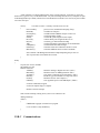
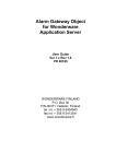
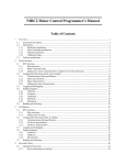
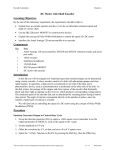
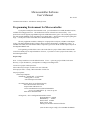
Microcontroller Software
User’s Manual
Rev 9/1/05
Comments/corrections to: Alex Brown [email protected]
Programming Environment for Microcontroller.
If you plan to modify the microcontroller code, you will need the ICC12 IDE (Standard version)
available from imagegecraft.com . The Professional version will work but is not necessary. The
professional version supports paged addressing in the 256K flash memory space. The current program uses
only 26K and the Standard version can address up to (about) 40K. I don't foresee this program getting this
large. A 30 day trial version of the IDE can be downloaded from imagecraft.
The only equipment needed is a desktop PC or laptop with a serial port (a USB to serial adapter
works). The laptop should also have a floppy disk to read/store license data (a USB floppy works). A
standard serial cable (not a null modem cable) is required to go between the PC and the 9 pin serial port on
the Adapt9S12DP256 card.
I will generally provide all the source code in the form of a project folder which contains all the
source files and the project setup information. However, if you have to create a project from scratch, use
the following directions.
Project setup
Note: I always install ICC12 to the default location C:/ICC. I place my project folders in the same
directory. If you do otherwise, you might have to change some things below.
Create a new project with Project/New.
Select a directory to keep it in (make a new one if desired).
Pick a project name. Usually “Microcontroller” for this one.
Set project options:
Select Project/Options
on Paths tab, Include path: c:\icc\include\
Library path: C:\icc\lib\
asm and output can be blank
on Compiler tab, check Accept Extensions only
macro define entries can be blank
output format is Motorola s19
execute command after successful build should be:
../sreccvt -m c0000 fffff 32 -lp -o out.s19 %p.s19
other entries should be blank
on Target tab, device configuration should be Custom
Program Memory: 0x4000
Data Memory:
0x1000
Stack Pointer: 0x4000
Printf version: float
nothing else should be checked or filled in.
(note: the above target config is for a standard 9S12DP256
with code residing in flash memory. The Debug12 utility
must be erased at programming time.)
Click "set as default" then "OK"
Copy all source files into the directory. (all *.c and *.h)
Go to the Project/Add File(s) option and place all the above source files in the project.
There is an apparent typo in the hcs12dp256.h file in the ICC/INCLUDE folder (at least the
register name in the include file didn't agree with the processor documentation . So, change this
file as follows. This way, either spelling works.
Following line:
Add:
#define PWMPRCLC _P(0xA3)
#define PWMPRCLK _P(0xA3
The file: SRecCvt.exe must be placed in the ICC folder. You can put it elsewhere, but you'll have
to modify the " execute command after successful build" line above.
The ICC12 IDE generates .s19 files which can be bootloaded into an HC12 processor. The .s19
file generated is not compatible with the paged memory of the 9S12DP256 version. The SRecCvt
program (as directed by the "execute command after successful build" string converts the
generated .s19 file to a converted file called out.s19.
Now, you should be able to hit the "build project" button, or select Project/Rebuild all and have a
successful compilation and generation of an out.s19 file that can be loaded into the processor.
Bootloader:
First, you should have a standard serial cable hooked from the Com port of your PC to the 9 pin connector
on the Adapt9S12. I'm going to assume your PC communicates on COM1 for the explanation, if it doesn't
work, you can try COM 2 etc. Or look in the Device Manger to see which port you are set to.
Bring up the ICC12 IDE.
Go to Tools/ Environment Options/ Terminal...and set:
COM Port to COM 1
Baudrate to 9600
Flow Control to None (Software(^S/^Q) also works, I believe)
ASCII transfer protocol to None.
Hit OK.
Select Terminal/ Show Terminal Window (this should bring up the blank terminal display.
Hit the Open Com Port button. (the button will change to read "Close Com Port")
Switch the RUN/PROG switch to the PROG position .
With 12 vdc power applied to your controller board, the green light on the processor should be on.
Press the reset button on the Adapt9S12DP256 board (right upper corner).
You should get the following menu page starting:
D-Bug 12 Bootloader......
If you don't get the bootloader, make sure you have moved the Mode Select jumpers on the Adapt board
from the 0 to the 1 position. Or you might try other COM ports.
Once you get the menu:
If there is no cursor on the terminal page, click on the page.
press the "a" key to erase the flash memory. The menu should reappear within 5 seconds.
Use the browse button to select the out.s19 file generated above.
press the "b" key to program the flash memory.
Hit the Download button to actually sent the file.
A progress indicator on the top will move from left to right. This may take a couple minutes.
When done, several rows of asterisks will appear on the screen followed by the menu.
The program has loaded.
Place the RUN/PROG switch to the RUN position.
Reset the terminal baud rate to 115K
Hit the reset button.
You should see the words "Processor is Running!" on the screen.
More may be printed afterwards depending on what is in the program.
Congratulations are in order, I hope!
Essential documentation:
Schematic and connector pinout lists usually supplied by Technological Arts with each board
purchased.
"MC9S12DP256 Advance Information" Google on this and it will find you the motorola website.
Or, just go to: http://www.datasheetcatalog.com/motorola/75/ This document contains all of the
programming information.
Motorola has much more documentation on the various functions in the processor, but the above
"Advance Information" manual covers most all of it.
SRecCvt and documentation. Google on SRecCvt or :
http://homepage.mac.com/WebObjects/FileSharing.woa/65/wo/kX5IgoKx0YHyRPOw.1/0.2.1.2.2
2.31.97.2.35.0.1.1.1?user=rbarris&fpath=OSX_SRecCvt&templatefn=FileSharing1.html
Microcontroller software
General:
Almost all math is performed in fixed point. This is because the Motorola chip does not have
hardware floating point and the software floating point package is much slower (and I am a speed freak!).
One exception is in the Navigation module where I use floating point to calculate X and Y
coordinates accurately using triginometric functions.
Sometimes long ints are used for improved resolution.
RC.C
Real time executive
Overview:
A real-time system usually
consists of a set of code that is executed
periodically at a consistent rate. This is
implemented with a hardware function
that calls the real-time set of code at a
rate based on a hardware clock.
As shown to the right, the
program first initializes itself and then
starts the real-time interrupt. The main
program then enters a loop, often called
the Background loop, where it runs
forever and may perform useful
computations.
In parallel, the hardware realtime interrupt will call a defined set of
software to execute. When called, the main program is interrupted from its background tasks. The realtime tasks are all executed and then the program returns to the background loop and continues execution
there.
One important constraint on a real time system is that the real-time tasks should all be completed
before the next interrupt occurs. If not, the real-time tasks will be interrupted and start again from the
beginning. When they are completed, hopefully on time this cycle, the remaining tasks from the last cycle
will be completed. This can result in data corruption since the completing cycle will not be operating on
the same data set as the first part of the cycle which was interrupted. This can only be solved with a lot of
context switching which creates a lot of trouble, in my opinion. The easier solution is to ensure that the
real-time tasks can always complete on time. Basically this means that no blocking functions should exist.
That is, any task which can not be completed immediately should be deferred to the next cycle.
Details:
The following is an overview of the real time software for the Leaf microcontroller. It should help
to understand the code of RC.c.
main() initializes everything and then turns on the real time interrupt. From then on, the items
under rtexec(); get run every 16.384 milliseconds. Any time remaining after the rtexec() completes is spent
in the Background loop of main() which will execute the Built in test mode if it is selected, or print out data
sets to the serial port.
rtexec()
{
// real time executive. Called by real time clock at 61 hz
ProcessCmds();
DIOread();
I2Ccompass();
Analogs();
Sonar();
RCservo();
DGyro();
Tilt();
USBupdate();
Odometry();
MotorExec();
processes new commands from laptop (if any)
reads discrete I/O ports
reads Devantech CMPS03 compass via I2C bus.
reads in all analog signals.
reads all RC ports assigned as sonar inputs
controls all RC ports assigned as RC servos
reads rate gyro and calculates heading
reads accelerometers and calculates accel and attitudes
reads and transmits USB messages.
Calculates wheel travel distances and X/Y coords
Calculates PWM to achieve motion commands.
Store a dataset if the Background mode has completed printing the previous set.
Test if operator has selected Built in test mode.
}
main()
{
Set processor clock to 24 MHz
Set baudrate to 115K
Initialize functions:
ATDinit();
MotorInit();
AccelInit();
RGnull();
I2Cinit();
USBinit();
Initializes Analog to Digital converters (Init.c)
Initializes timers for PWM generation (Init.c)
Sets up Port J interrupts for accelerometers (Init.c)
Reads rate gyro and calculates average null (DG.c)
Initializes I2C bus (I2Ccompass.c)
Sets up parallel port to read USB adapter (USB.c)
set motor command to stopped
set motion complete flags to complete
initialize real time interrupt
Start real time interrupt (causing rtexec() above to be called at 61 hz.
//Background loop
while(1)
{
if BITEmode engaged, run built in test program
if a set of data is ready, DataPrint();
}
USB.C
Communications:
The microcontroller communicates with the laptop computer over a USB data bus. Currently,
there is a single data message transmitted from the microcontroller to the laptop which contains sensor data,
computed data, and various status messages. There are several messages which are transmitted from the
laptop to the microcontroller; there is a command message which tells the microcontroller what to do, and
there are several configuration and calibration messages which are sent from the laptop at initialization
time.
This function is the USBupdate() function that is called every 16 milliseconds. It transmits a data
message to the laptop every 64 msec and looks for new messages from the laptop every 16 msec.
Every 64 milliseconds, //every 4th cycle
{
Load output message buffer with current data [ USBmsgfill()]
Set message counter for transmission
}
Send message to USB adapter
[USBsendmsg()]
Read input message
[USBreadmsg()]
return
When the send and read message functions are called, there is no assurance that they will be able
to complete their tasks in a timely manner. The Laptop may have sent only a partial message to the
microcontroller or the send buffer of the USB adapter may be full. Hence, each of these functions has a
counter, USBsendidx and USBreadidx which keeps track of the amount of data that has been sent or
received.
USBsendmsg() transfers the output message to the USB adapter buffer until it indicates full; then
it returns with USBsendidx set to the amount of data transferred. USBupdate will continue to call
USBsendmsg each cycle until the counter indicates that the entire message has been transmitted.
Similarly, USBreadmsg() returns when the USB input buffer is empty and USBreadidx reports
the amount of data received. USBupdate will continue to call USBreadmsg until it reports that a complete
message has been received. At this time, it copies the message to another buffer for export to the
ProcessCmds function and sets seqnumUSB to the new message sequence number so that ProcessCmds can
recognize that a new message has been received.
This technique avoids the need to wait for USB system to complete message transmissions and
avoids exceeding the real time executive frame time.
ProcessCmds.C
handle command messages:
The next highest level function is processing command messages from the Laptop computer and
sending those commands to the various microcontroller functions to be executed.
Each cycle, ProcessCmds() reads the seqnum of the current input message. If it is the same as the
seqnum of the last message processed, it returns. Otherwise it processes the new message. (note:
sequence numbers are incremented by the laptop for each message with new content. A message with a
unique seqnum may be transmitted multiple times)
ProcessCmds() reads the message type identifier in the message and calls the appropriate function
to handle that message type. Currently, there is one message for commands from the laptop to the
microcontroller and several messages sent at initialization to configure and calibrate the microcontroller.
The ProcessCmdMsg() function reads motor drive commands and Discrete output commands from
the message and calls functions in the motors.c module and the DIO.c module to set up the specified
commands.
The configuration and calibration messages generally read the message and store the information
directly to memory. An exception is the ProcessConfigMsg1() function which calls the TimerInit() and
DIOinit() functions. These two functions are really part of the basic processor initialization but are not
able to be completed until the required configuration information has been received.
DataLog.c
Datalog provides the capability of printing out data during every processor frame for analysis or
troubleshooting. The data is formatted in such a way as to be compatible with the DataPlot utility program.
A data printout can be requested by a message from the laptop computer. The resulting printout
can be captured from the RS232 serial bus on the microcontroller at 115K baud to a file using any terminal
emulator program. A subsequent command message can turn off the printout. The data log messages
consist of a single integer (2 bytes) from the laptop which specify “turn data logging on” (bit 15 set), “turn
data logging off” (bit 14 set) and the dataset number (bits 0 to 7). This integer is processed by
ProcessCmds() which sets two variables .
These two variables control the data logging. DataLogOn gives the logging status; and DataCase
specifies the particular data set desired. A zero means that data logging is OFF, a 1 means that logging has
been requested by the laptop. DataPrint() is the executive for data logging and is called for each processor
cycle. If it receives a value of 1 for DataLogOn, it prints out the appropriate header file and then sets
DataLogOn to “2”. If a “2” is seen, DataPrint sends out the appropriate data string.
The data format consists of a header which identifies all the parameters being recorded followed
by a set of data printed each cycle (61 sets per second). See DataLog.c for an example of the header format
and the data print statements.
Since the data is printed out in background mode, only as many parameters can be printed during
each frame as can be handled in the time remaining after the real time functions. If the print can not be
completed before the next real time interrupt, it will be completed following the next frame. In this event,
one frames data will be skipped. For this reason (and others), the first data parameter should always be
“time” so that manual and automatic data review can recognize where data has been skipped.
Most aspects of data logging are controlled by the executive DataPrint noted above. However,
the data is actually written to the Data string for printout in the real time executive (rtexec() in
Microcontroller.c) so that a data set is always associated with a particular frame. A variable called LogFlag
is used to ensure that new data is not stored into the Data string until the previous string has completed
printing.
(The following are very abbreviated descriptions of the remaining modules. They
will be elaborated later.)
NAVIGATION.C
Currently just performs odometry, generates wheel speed and distances and some basic dead reckoning
calculations.
MOTORS.C
This module has three functions all called as MotorExec() from the realtime executive.
Steering() calculates differential wheel acceleration, speed and distance commands to comply with steering
commands sent from the laptop.
MotorCmd() calculates wheel acceleration, speed and distance commands to travel forward or reverse as
commanded by the laptop.
The Steering and MotorCmd calculations are summed to generate commands for each of the drive wheels.
Motor() calculates PWM signals for each motor to track to the above commands.
ANALOGS.C
Called every cycle to read the current values of the analog input ports and places the results in global
memory for use by microcontroller functions (none currently) and transmission to the laptop for navigation.
SONAR.C
Reads up to 7 SRF04 sonar range sensors. (selectable in software from 0 to 7) It cycles through the number
of sonars using two cycles to read each.
RCSERVOS.C
Radio control servos can use the same output ports as the sonar signals above and are alternatives in
software. If signals 0 to 3 are sonar, then 4 to 6 are defined as RC servos.
This function generates signals to drive each RC servo to the position commanded by the laptop (not
implemented yet). The command can be to a specific position, or to cycle back and forth between two
specified positions for scanning of sensors.
DG.C
This module is responsible for implementing a directional gyro signal by integrating the yaw rate gyro
installed on the microcontroller board. It has an RGnull() function which is executed at power up and reads
100000 values of the yaw rate gyro to determine an accurate null value.
Each real time cycle, it reads the yaw rate gyro and calculates turn rate and integrates the rate gyro to
determine the robot's heading.
I2CCOMPASS.C
Reads the current heading from a Devantech CMPS03 compass. This is implemented as an interrupt
interface hence this function just starts the transaction and the interrupts.c module finishes it.
ACCEL.C
Reads a dual axis accelerometer chip and makes the results available as filtered acceleration signals and
estimates of pitch and roll axis tilt.
BATTMON.C
Reads the battery voltage and converts it to volts
INTERRUPTS.C
Provides interrupt handlers for:
Calling the real time executive and counting time. (time increments 1 per cycle, i.e. 61 per second)
Reads drive motor quadrature encoders. These store to a long integer (32 bits) and are implemented in
assembly for speed.
Read the two interrupts for the accelerometer signals.
Process the reading of the I2C compass signal.
BITE.C
Built in test function. This tests most input sensors and motor drive outputs over the serial bus connected to
a terminal. This mode is engaged by selecting ESC on the keyboard when the robot is stopped.
VECTORS.C
Sets up all the necessary interrupt vectors
IOCHAR.C
Sends printf bytes to the serial bus.
COMMAND MESSAGE from laptop Nav and Control to microcontroller
Note: words are 16 bits (2 bytes)
revised 8-18-05
Word
Value
0
start word
1
time tag
Sequential number of command message. Unique to each new message (with new
data). Same number should be used on repeated transmissions of same message.
2
msg type
3
spare
4
FwdCmd
currently FFA5
Message type identifier. (not used)
(this will be an integer value selecting the commanded mode of forward or reverse
motion which may be high level (e.g. explore) or low level (e.g. forward 1 meter)
This command is also used to select high level activities.
0
None
this message has no command for forward motion
1
Proceed straight forward or backwards starting from a stopped condition.
Starts distance reference at zero.
(see words 3 and 4 for parameters)
3
Modify the acceleration, velocity or distance of an on-going FwdCmd. This command
will work even if the on-going command has completed and stopped. But the initial
distance reference remains the same as the original command.
5
Stop
causes an on-going FwdCmd to halt immediately. Only the deceleration rate is
specified (see word 4 for parameter)
5
spare
6
accel command sets maximum acceleration to be used during both acceleration and deceleration.
Defaults to 300 mm/sec^2 if not set (zero value). Sign does not matter.
Normally in the range of 50 to 500.
7
speed command maximum speed applied to commands 1 and 3 above. speed is in
millimeters/second . Robot will accelerate
or decelerate to commanded speed at the specified accel rate. Sign does not
matter. Normally in the range 10 to 400.
8/9
distance command distance robot should proceed at the commanded speed. Robot will
automatically come to a stop at the specified distance.
To move without having a specified distance, command a distance which is very
far; e.g. +/- 200000000.
Distance command is + for forward and – for backwards.
Distance is measured from the last time a FwdCmd = 1 was sent . If
the distance is changed with FwdCmd = 3 while a distance is already set, the
robot will proceed to the new distance; the start point will remain where it was
originally set.
10
Turn Cmd
This is an integer number selected a particular mode of steering.
Turning may be done while the robot is moving forward or stopped. If stopped,
the result is to pivot in place.
0
None
no steering command is sent in this message
1
Turn
3
This mode controls direction with respect to wheel encoder data. The distance
to turn is always with respect to the starting point when the mode is engages.
(see words 9 thru 11 for parameters)
Modify turn
5
Stop turn
(note: Following commands 10 – 25 are not yet implemented)
10
HdgSel This mode controls direction with respect to the heading signal derived from
the yaw rate gyro and compass. Heading can be specified from –360 to
+360. Robot will turn the shortest direction from the current to new heading.
(see words 9 thru 11 for parameters)
13
Modify hdg
15
Stop hdg turn
20
Radius turn
23
Modify radius turn
25
stop radius turn
11
spare
12
Turn Accel
matter.
turn acceleration rate in deg/sec^2 *10 (normally about 300). Sign doesn’t
13
Turn rate
rate at which robot should turn or pivot in degrees per second *10. Normally in
range of 50 to 600. Sign doesn’t matter.
14/15
Turn distance
how far the robot should turn in degrees * 10. 30 degrees is “300”.
+ is to the right, - to the left. (clockwise is to the right)
If want to turn continuously, use a very large number; e.g. +/ 200000000
16
DG control
provisions
17
DG set
provisions
18/19
Xcoord set
provisions
20/21
Ycoord set
provisions
22
DIOcommand
23
RC0 param0
RC servo 0, rate/select
24
RC0 param1
RC servo 0, Left limit/command
25
RC0 param2
RC servo 0, Right limit/mode
26/27/28
(same for RC servo 1)
29/30/31
(same for RC servo 2)
32/33/34
(same for RC servo 3)
35/36/37
(same for RC servo 4)
38/39/40
(same for RC servo 5)
41/42/43
(same for RC servo 6)
44
MCDatalogcmd Data logging command word
Notes on use of robot motion control commands.
Forward and reverse motion may be commanded and modified at most any time.
Motion may be commanded in either the forward (+) or reverse (-) directions. The Distance parameter
specifies the direction of motion. The Acceleration and Velocity maximum parameters apply to both
forward and reverse motion and acceleration and deceleration. The sign of these two parameters does not
affect the results. Normally no sign is used.
A value of distance must be supplied, if only to specify direction of motion. Normally the robot will
accelerate to the maximum specified velocity at the specified acceleration. It will travel toward the target
distance at the maximum velocity and compute when to decelerate (at the specified acceleration) to stop at
the specified distance.
If you want the robot to continue travelling for an indefinite distance (until you tell it to stop ), choose a
very large value for distance that the robot will never get to. A value of +/- 2000000000 ( 2000 KM)
should do.
If the robot is traveling forward, you can send modified parameters using FwdCmd = 3. The robot will
continue motion but will transition to the new parameters. Maximum velocity can be modified to be larger
or smaller and the robot will speed up, or slow down. Acceleration can be modified and will affect any
ongoing or future speed changes. If the robot cannot achieve the commanded velocity due to motor
speed limitations, ramps, deep rugs etc, it will continue at the highest speed it can manage.
Distance can be changed at any time. Direction can even be reversed and the robot will slow to a stop and
then proceed toward the new target. Even after the robot has completed a forward motion command and
come to a stop, specifying a new distance with FwdCmd = 3 will cause the robot to restart and go to the
new target.
If an explicit stop command has been sent (FwdCmd = 5), subsequent FwdCmd = 3 commands will have
no effect. You must use a new FwdCmd = 1 message to start a new motion.
Notes:
Correlation between DIOcmd word and modular jack pins:
DIOcmd bit
15
14
13
12
11
10
9
8
7
6
5
4
3
2
1
0
no connection
no connection
no connection
no connection
DIO2 pin 5
DIO2 pin 4
DIO2 pin 3
DIO2 pin 2
DIO1 pin 5
DIO1 pin 4
DIO1 pin 3
DIO1 pin 2
DIO0 pin 5
DIO0 pin 4
DIO0 pin 3
DIO0 pin 2