1
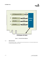
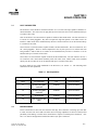
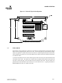
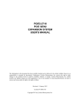
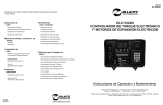
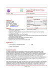
PCIE2-437
USER’S MANUAL
The information in this document has been carefully checked and is believed to be entirely reliable. However, no
responsibility is assumed for inaccuracies. Furthermore, Cyclone Microsystems, Inc. reserves the right to make
changes to any products herein to improve reliability, function, or design. Cyclone Microsystems, Inc. neither
assumes any liability arising out of the application or use of any product or circuit described herein, nor does it
convey any license under its right or the rights of others.
Revision 1.0, December 2010
Copyright 2010 by Cyclone Microsystems, Inc.
CONTENTS
CHAPTER 1
1.1
INTRODUCTION ..............................................................................................................................1-1
1.2
SPECIFICATIONS............................................................................................................................1-2
1.3
STANDARDS ...................................................................................................................................1-3
1.4
ORDERING INFORMATION ............................................................................................................1-3
CHAPTER 2
2.1
THEORY OF OPERATION ..............................................................................................................2-1
CHAPTER 3
3.1
SLOT CAPABILITIES .......................................................................................................................3-1
3.2
BOARD POWER ..............................................................................................................................3-1
3.3
POWER CONNECTOR....................................................................................................................3-2
3.4
LINKED LED INDICATORS .............................................................................................................3-3
3.5
BOARD COOLING ...........................................................................................................................3-4
3.6
BOARD MECHANICALS..................................................................................................................3-4
3.7
FLEX CABLES .................................................................................................................................3-5
i
PCIe2-437 User’s Manual
Revision 1.0, December 2010
CONTENTS
LIST OF FIGURES
Figure 1-1.
PCIe2-437 Block Diagram ...................................................................................................1-2
Figure 3-1.
PCIe2-437 Physical Configuration.......................................................................................3-5
LIST OF TABLES
Table 1-1.
Table 3-1
Specifications ......................................................................................................................1-3
Slot Capabilities...................................................................................................................3-1
Table 3-2
Power Requirements ...........................................................................................................3-2
Table 3-3
Power Supplied Per PCIe Slot.............................................................................................3-2
Table 3-4
Power Connector.................................................................................................................3-3
Table 3-5
Link LED Definition ..............................................................................................................3-3
ii
PCIe2-437 User’s Manual
Revision 1.0, December 2010
CHAPTER 1
INTRODUCTION
1.1
INTRODUCTION
The Cyclone Microsystems PCIe2-437 Four Slot Riser Card is a PCI Express (PCIe) add-in board that
allows the user to expand a host slot from one to four slots. Most PCs contain few PCI Express slots
making them poorly suited for embedded system developers to use powerful and cost-effective PCs as a
foundation for a robust embedded system.
The PCIe2-437 Four Slot Riser Card host interface is a x16 (electrical and mechanical) Gen2 card edge.
The riser card’s slots are x4 electrical, organized as one x16 mechanical slot and three x8 mechanical
slots. All are Gen2 capable. Each slot of the riser card will support a flex cable attachment to its
respective add-in card. Additionally, the riser card can be attached to its host slot via a flex cable.
Using flex cables allows the PCIe2-437 riser card to be used as an “internal expansion board”.
The PCIe2-437 Four Slot Riser Card supports 80 Gbit/s bi-directional traffic to and from the host
system and 20Gbit/s bi-directional traffic to and from each slot. The system uses a non-blocking PCI
Express switch for excellent peer-to-peer I/O bandwidth. The PCIe2-437 is recognized by the host
system upon boot-up, requires no hardward specific drivers and is entirely host operating system
agnostic.
PCI Express is a high performance, general purpose I/O inter-connect defined for a wide variety of
computing and communication platforms. Key PCI attributes, such as its usage model, load-store architecture, and software interfaces are maintained, whereas its parallel bus implementation is replaced by a
serial interface. PCI Express take advantage of recent advances in point-to-point inter-connects, switchbased technology, and packetized protocol to deliver new levels of performance.
PCIe2-437 User’s Manual
Revision 1.0, December 2010
1-1
INTRODUCTION
x4 Gen2
J4
PCI-Express x16 Slot
J3
PCIe x8 Slot
J2
PCIe x8 Slot
J1
PCIe x8 Slot
x4 Gen2
x4 Gen2
PCI-Express
Switch
x4 Gen2
PCI-Express x16 Gen2
Figure 1-1. PCIe2-437 Block Diagram
1.2
SPECIFICATIONS
The specifications in Table 1-1 detail the PCIe2-437 Four Slot Riser Card. The physical dimensions do
not include attached boards or flex cables.
1-2
PCIe2-437 User’s Manual
Revision 1.0, December 2010
INTRODUCTION
Table 1-1. Specifications
Physical
Electrical
Board Height
4.199 inches
Board Length
5.750 inches
Component Height
0.554 inches
Voltage
+3.3VDC +/- 9%
+12VDC +/- 8%
Environmental
1.3
Input Current (no boards
installed)
2A for +3.3VDC,
Input Current (Four 75W PCIe
Cards installed)
14A for +3.3VDC,
Operating Temperature
0 to 50 Degrees Celsius
Relative Humidity
0% to 95% (non-condensing)
Storage Temperature
-20 to 70 Degrees Celsius
0A for +12VDC.
22A for +12VDC.
STANDARDS
PCI Express Base Specification Revision 2.0
PCI Express Card Electro Mechanical Specification 2.0
1.4
ORDERING INFORMATION
Cyclone Part Numbers
CM437
PCIe2-437 User’s Manual
Revision 1.0, December 2010
PCIe2-437 Four Slot Riser Card
1-3
CHAPTER 2
THEORY OF OPERATION
2.1
THEORY OF OPERATION
The basic PCI Express link consists of dual unidirectional differential links, implemented as a transmit
pair and a receive pair. The signaling rate for PCI Express Gen2 is 5.0 Gigabits/second/Lane/direction.
A link supports at least one lane.
The PCI Express link at the PCIe2-437 card edge is a sixteen lane (x16) link. The PCIe2-437 provides
three slots with x8 connectors (slots J1, J2, J3) and one slot with a x16 connector (slot J4). All slots are
four lane (x4) links. All slots can accommodate single lane (x1), x4 or x8 add-in cards. Additionally,
slots J1, J2 and J4 will accept x16 add-in cards. Although not expressly permitted by the PCI Express
Specification, slots J1 and J2 accommodate “down-shifting” a x16 card into a x8 slot. Plugging a
smaller link card into a larger link connector is fully allowed.
The system is ready to be turned on once the PCIe2-437 is installed into the host PC (either directly or
with flex cable), the power cable is connected to the PCIe2-437 and any desired add-in cards are
installed (again, either directly or with flex cable). When the host is turned on, the PCI Express links are
initialized. This is a purely hardware initialization where each PCI Express link is set up following a
negotiation of lane widths by the two ends of each link. No firmware or operating system software is
involved. Once the links are initialized or “trained”, there are LEDs on the PCIe2-437 that provide a
visual indication of link status. A detailed explanation of the LEDs follows later in this manual.
One essential requirement for system initialization is the ability of the host system’s BIOS to be able to
enumerate the many bridges inherent in a complex PCI Express design. The links from the host to the
PCIe2-437 slots are created with a PCI Express Switch. Each link looks like a PCI-to-PCI bridge to the
Host’s BIOS. The number of bridges can add up quickly. Older BIOS may not have the resources to
enumerate the number of bridges. Make sure that the BIOS on the host computer has the latest updated
BIOS. If required, contact the host system’s manufacturer to make sure that the BIOS used can handle
the large number of bridges that it will see in the system.
PCIe2-437 User’s Manual
Revision 1.0, December 2010
2-1
CHAPTER 3
BOARD OPERATION
3.1
SLOT CAPABILITIES
The PCIe2-437 Four Slot Riser Card host interface is a x16 Gen2 card edge capable of 80Gbit/s bidirectional traffic. The PCIe2-437 can plug directly into a host PCIe slot or can be attached with up to
12 inches of flex cable.
Slots J1 and J2 have x4 Gen2 interfaces capable of 20Gb/s bi-directional traffic. The slot connectors at
J1 and J2 are “down pluggable”, they have an open back edge that permits a x16 add-in card to be
installed. Add-in cards can be installed directly into the J1 and J2 connectors or can be attached with up
to 12 inches of flex cable.
Slot J3 also has a x4 Gen2 interface capable of 20Gb/s bi-directional traffic. The slot connector at J3 is
not “down pluggable”. There are board components in the way that prevent a x16 add-in card from
being installed. Add-in cards x8 or smaller can be installed directly into the J3 connector or can be
attached with up to 12 inches of flex cable.
Slot J4 has a x4 Gen2 interface capable of 20Gb/s bi-directional traffic. The slot connector at J4 is a
x16 connector with a board latch commonly used with video cards. Add-in cards can be installed
directly into the J4 connector or can be attached with up to 12 inches of flex cable.
For more details on flex cable attachment to the PCIe2-437, see section 3-7. The following table
summarizes the slot capabilities
Table 3-1. Slot Capabilities
3.2
Slot
Connector
Lanes
Flex Cable
Host
x16 card edge
x16
up to 12 inches
J1
x8 down pluggable
connector
x4 lanes
up to 12 inches
J2
x8 down pluggable
connector
x4 lanes
up to 12 inches
J3
x8 connector
x4 lanes
up to 12 inches
J4
x16 connector with
latch
x4 lanes
up to 12 inches
BOARD POWER
Power to the PCIe2-437 does not come from the card edge, host connection. Powering up to four addin cards from one host slot would exceed the current carrying capabilities of the host connector and
potentially cause damage. For this reason, the PCIe2-437 requires a external power connection; +12V
and +3.3V must be brought to the board from a Molex style power connector.
PCIe2-437 User’s Manual
Revision 1.0, December 2010
3-1
BOARD OPERATION
Table 3-2 shows the power requirements for the PCIe2-437.
Voltage
Table 3-2. Power Requirements
Tollerance
Current Minimum
Current Maximum
(no cards installed)
(Four 75W add-in
cards installed)
+3.3VDC
+/- 9%
2.00 Amps
14 Amps
+12VDC
+/- 8%
0.00 Amps*
22 Amps
* The PCIe2-437 does not use +12V, it only routes +12V to the slot connectors.
Each PCIe2-437 slot is a PCIe 75W slot. Some add-in cards, especially video cards, require more than
75W; these cards will have their own external Molex style power connector. Video card users should
verify that any external power connections to their cards have been made. Table 3-3 shows the
breakdown of power at each slot.
Table 3-3. Power Supplied Per PCIe Slot
Voltage
Current Maximum
3.3
+3.3V
3.0 Amps
+12V
5.5 Amps
POWER CONNECTOR
For the reasons stated in the previous section, the PCIe2-437 requires an external power connection.
The power connector J9 on the board is a Molex 39-30-0100. Customers must make their own cable to
connect J9 on the PCIe2-437 to a +12V & +3.3V power source. The mating connector housing to J9 is
Molex 39-01-2100 (UL94V-2 nylon, natural color) and there are other housings in this series that will
work. This connector style uses discrete contacts crimped to the wires and inserted into the housing.
Typical contact is Molex 39-00-0060 for 18-24AWG wire. The crimping tool is Molex 63819-0900.
The pinout of J9 is: pins 6-7-8 are +12V, pins 9-10 are +3.3V and pins 1-2-3-4-5 are ground. Each
contact position is labeled on the housing at the wire insertion openings
3-2
PCIe2-437 User’s Manual
Revision 1.0, December 2010
BOARD OPERATION
Table 3-4. Power Connector
3.4
J9-1
GND
J9-2
GND
J9-3
GND
J9-4
GND
J9-5
GND
J9-6
+12V
J9-7
+12V
J9-8
+12V
J9-9
+3.3V
J9-10
+3.3V
Mating housing (typ)
Molex 39-01-2100
Contact (18-24AWG)
Molex 39-00-0060
Crimping tool
Molex 63819-0900
LINK LED INDICATORS
The PCIe2-437 has LEDs to indicate the PCIe link status of each slot and the host connection. The five
surface mount, green LEDs are arranged in a row on the edge of the board opposite the host card edge
connector, see Figure 3-1. The LEDs are labeled J1, J2, J3, J4 and HOST.
A fully functional link (all lanes used and operating at Gen2 rates) will have its LED ON solid. A link
running at Gen1 rates and/or using less lanes than available will indicate status with a blinking LED.
The LEDs indicate link status as follows:
Table 3-5. Link LED Definition
Link is down
OFF
ON
Link is up, all lanes, Gen2 (5GT/s) rate.
BLINK: 0.5 seconds ON, 0.5 seconds OFF
Link is up, reduced lanes, Gen2 (5GT/s rate)
BLINK: 1.5 seconds ON, 0.5 seconds OFF
Link is up, all lanes, Gen1 (2.5GT/s rate).
BLINK: 0.5 seconds ON, 1.5 seconds OFF
Link is up, reduced lanes, Gen1 (2.5GT/s rate).
There is a sixth surface mount, green LED labeled PWR. When lit, this LED indicates there is +3.3V
power to the board. It is also located on the edge opposite the host card edge connector. There is no
indicator for +12V power.
PCIe2-437 User’s Manual
Revision 1.0, December 2010
3-3
BOARD OPERATION
3.5
BOARD COOLING
The PCIe switch is the only part on the PCIe2-437 that requires cooling. The part dissapates about 3W
typical and 6.5W maximum. The manufacturer defines typical as 35% traffic (voltage rails at their
nominal voltage) and defines maximum as 85% traffic (voltage rails at their maximum). At the 6.5W
maximum, the heatsink used on the PCIe switch will require about 200lfm (2m/s) of airflow.
For most users, just allowing the heatsink to radiate should be sufficient. For power users or applications where flex cable is covering the board, users must ensure there is adaquate airflow across the fins
of the heatsink.
3.6
BOARD MECHANICALS
Figure 3-1 is a mechanical drawing of the PCIe2-437 Four Slot Riser Card. As the drawing shows, the
boards’ overall dimensions are 4.366in x 5.750in. The card edge connector is to the x16 PCIe specification including the “hockey stick” latch mechanism. The mounting holes are 0.125in, suitable for #4
screws located at each corner.
The tallest components on the board are the PCIe connectors (0.440in), the PCIe switch with heatsink
(0.554in) and the power connector (0.396in).
3-4
PCIe2-437 User’s Manual
Revision 1.0, December 2010
BOARD OPERATION
Figure 3-1. PCIe2-437 Physical Configuration
3.7
FLEX CABLES
The PCIe2-437 can be used like a typical riser card, where it is plugged directly into the host and the
add-in cards are plugged directly into the riser card. In most host systems, this mechanical configuration is not practical. To make the PCIe2-437 more like an “internal expansion board” the PCIe2-437
can be attached to the host slot via a flex cable and like-wise, add-in cards can be attached to the PCIe2437 with flex cables.
Cyclone has tested the PCIe2-437 with a 12inch long flex cable to the host system and with add-in cards
on 12inches of flex cable. The cables have a small section of printed circuit board on each end of the
flex cable, a PCIe card edge on one end and a PCIe slot connector on the other. The flex cables were
purchased from Adex Electronics in Lake Forest CA (www.adexelec.com). A typical part number is
PEFLEX16RG212 for the x16, 12inch, Gen2 cable.
PCIe2-437 User’s Manual
Revision 1.0, December 2010
3-5