1
ECOLOR 250 XT
Table of contents
1. Safety instructions ........................................................................................................ 3
2.Operating determinations .............................................................................................. 4
3.Description of the device ............................................................................................... 5
4.Installation ....................................................................................................................... 7
4.1Fitting/Exchanging the lamp ........................................................................................ 7
4.2Lamp adjustment ........................................................................................................ 7
4.3 Manually adjustment of the effects .............................................................................. 8
4.4 Rigging ...................................................................................................................... 9
4.5Connection to the mains ............................................................................................ 10
4.6 DMX- 512 connection, master/slave connection ....................................................... 11
5. DMX Protocol-8 bit ....................................................................................................... 12
6.Control of the fixture .................................................................................................... 13
7.Controller mode ............................................................................................................ 13
7.1 DMX addressing ...................................................................................................... 13
7.2 Remotely and manually controllable functions ........................................................... 14
8. Stand - alone mode ..................................................................................................... 14
9. Functions of the control panel ................................................................................... 16
9.1 Addressing .............................................................................................................. 16
9.2 Slave control ............................................................................................................ 17
9.3 Fixture informations .................................................................................................. 17
9.4 Personality options ................................................................................................... 18
9.5 Switching On/Off the lamp ........................................................................................ 21
9.6 Test sequences ........................................................................................................ 21
9.7 Stand-alone setting .................................................................................................. 22
9.8 Reset function .......................................................................................................... 25
9.9 Special functions ...................................................................................................... 26
10. Error and information messages.............................................................................. 28
11.Technical specifications............................................................................................. 28
12. Maintenance and cleaning ........................................................................................ 30
13. Appendix .................................................................................................................... 32
2
CAUTION!
Keep this device away from rain and moisture!
Unplug mains lead before opening the housing!
FOR YOUR OWN SAFETY, PLEASE READ THIS USER MANUAL CAREFULLY
BEFORE YOU INITIAL START - UP!
1. Safety instructions
Caution ! Be careful with your operations.With a dangerous voltage you can suffer
a dangerous electric shock when touching the wires
This device has left our premises in absolutely perfect condition. In order to maintain this condition and to ensure
a safe operation, it is absolutely necessary for the user to follow the safety instructions and warning notes written
in this manual.
Important:
Damages caused by the disregard of this user manual are not subject to warranty. The dealer will not accept
liability for any resulting defects or problems.
If the device has been exposed to drastic temperature fluctuation (e.g. after transportation), do not switch it on
immediately. The arising condensation water might damage your device. Leave the device switched off until it has
reached room temperature.
This device falls under protection-class I. The power plug must only be plugged into a protection class I outlet.
Never let the power-cord come into contact with other cables! Handle the power-cord and all connections with the
mains with particular caution!
Make sure that the power-cord is never crimped or damaged by sharp edges. Check the device and the powercord from time to time.
Always disconnect from the mains, when the device is not in use or before cleaning it.
During the initial start-up some smoke or smell may arise. This is a normal process and does not necessarily
mean that the device is defective.
Caution: During the operation, the housing becomes very hot.
Do not switch the device on and off in short intervals as this would reduce the lamp’s life.
HEALTH HAZARD!
Never look directly into the light source,as sensitive persons may suffer
an epileptic shock
( especially meant for epileptics) !
Please consider that damages caused by manual modifications to the device are not subject to warranty.
Keep away children and amateurs !
3
2.Operating determinations
This device is an architectural luminaire for creating decorative effects and was designed for outdoor use.
Never run the device without lamp!
Do not shake the device. Avoid brute force when installing or operating the device.
Weatherized design to IP65.
When choosing the installation-spot, please make sure that the device is not exposed to extreme heat, moisture
or dust. There should not be any cables lying around. You endanger your own and the safety of others!
The minimum distance between light-output and the illuminated surface must be more than 1,0 meter.
Make sure that the area below the installation place is blocked when rigging, derigging or servicing the fixture.
The exterior of the fixture becomes very hot,up to 110°C.Do not place the fixture in areas where accidental
contact is likely.
Only operate the fixture after having checked that the housing is firmly closed and all screws are tightly fastened.
The lamp must never be ignited if the objective-lens or any housing-cover is open, as discharge lamps may
explose and emit a high ultraviolet radiation, which may cause burns.
The maximum ambient temperature ta =40°C must never be exceeded.
CAUTION!
The lens has to be replaced when it is obviously damaged,
so that its function is impaired, e. g. due to cracks or deep scratches!
Operate the device only after having familiarized with its functions. Do not permit operation by persons not
qualified for operating the device. Most damages are the result of unprofessional operation!
CAUTION!
The lamp has to be replaced when it is damaged
or deformed due to the heat!
Please use the original packaging if the device is to be transported.
Please consider that unauthorized modifications on the device are forbidden due to safety reasons!
Never remove the serial barcode from the device as this would make the guarantee void.
If this device will be operated in any way different to the one described in this manual, the product may suffer
damages and the guarantee becomes void. Furthermore, any other operation may lead to dangers like shortcircuit, burns, electric shock, lamp explosion, crash etc.
4
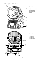
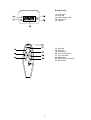
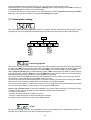
3.Description of the device
Front side
1
2
3
4
5
- Front cover of the head
- Rear cover of the head
- Bracket bolts
- Head bracket
- Base
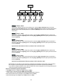
Rear side
6 - Lamp cover
7 - Patchcord
8 - DMX input
9 - DMX output
10 - Powercord
11 - Patchcord
5
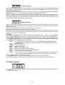
Display board
12 - Green LED
13 - Red LED
14 - Infra-red transceiver
15 - Light sensor
16 - Display
17 - Red LED
18 - Up-button
19 - Down-button
20 - Infra-red transmitter
21 - Lamp On-button
22 - Mode-button
23 - Blackout/lamp off-button
24 - Enter-button
6
4.Installation
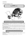
4.1Fitting/Exchanging the lamp
DANGER !
Unplug from mains before !
Lamp assembly
Lamp cover
Lamp
Rubber seal
Allow the lamp to cool for 20 minutes before removing the lamp cover
To insert the lamp MSD/HSD 250 open the small cover at the rear of the projection-head (see the drawing ) by
loosening the 4 screws on the cover.Remove the rubber seal.Loose the 4 screws ("V,X,Y,Z") on the lamp
assembly and gently pull the lamp assembly out.If changing the lamp, remove the old lamp from the socket.
Insert the lamp to the socket.
Do not install a lamp with a higher wattage! A lamp like this generates temperatures the device is not designed
for.
Damages caused by non-observance are not subject to warranty. Please follow the lamp manufacturer‘s notes!
Do not touch the glass bulb with bare hands during the installation! Make sure that the lamp is installed tightly
into the lampholder system.
Reinsert the lamp assembly and tighten the 4 screws ("V,X,Y,Z").Close the small lamp cover with the seal by
tighten the 4 fastening screws again.
Before striking the lamp, reset the "LAti/rSEt" and "LASt/rSEt"- counter in the "InFO" menu of the fixture, by
pressing the "Up" and "Down" buttons in one time and then confirming with the "Enter"-button on the remote
control.
Do not operate this fixture with opened housing-cover!
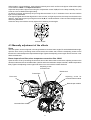
4.2Lamp adjustment
The fixture lampholder is aligned at the factory. Due to differences between lamps, fine adjustment may improve
light performance.
Open the lamp cover at the rear of the projection-head by loosening the 4 screws on the cover.
Remove the rubber seal.
7
Strike the lamp, cancel all effects, set the dimmer intensity onto 100 % and focus the light on a flat surface (wall)
or use function "LAAd" in the Special functions .
Adjust the lamp until the light is even using the 3 adjustment screws "A, B, C" on the lamp assembly. Turn one
screw at a time to distribute the light evenly.
To reduce a hot-spot, pull the lamp in by turning all three screws "A, B, C” clockwise 1/4-turn at a time until the
light is evenly distributed.
If the light is brighter around the edge than it is in the center, or if light output is low, the lamp is too far back in the
reflector. „Push” the lamp out by turning the screws "A, B, C" counterclockwise 1/4-turn at a time the light is bright
and evenly distributed.
Close the lamp cover with the seal by tighten the 4 fastening screws again.
Screws "A,B,C"
4.3 Manually adjustment of the effects
Zoom
The lens system can be configured in the range between 8° and 22° beam angles.To set the desired beam angle,
open the front cover by loosening the 8 screws,remove the rubber seal, loose the 2 adjusting screws on the
fresnel lens unit and adjust the required beam angle.Tighten the adjusting screws again and fix the front cover
with the rubber seal.
Beam shapers,frost filter,colour temperature correction filter 3200K
Open the front cover by loosening the 8 screws,remove the rubber seal.Loosen the 2 adjusting screws on the
desired module and set the suitable effect (vertical and horizontal beam shaper,frost filter, 3200K temperature
filter).Tighten the adjusting screws again and fix the front cover with the rubber seal back.
Adjusting screw
for fresnel unit
Rubber seal
Fresnel lens
Front cover
Adjusting screw for
correction filters module
Beam shaper module
Correction filter module
8
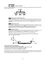
4.4 Rigging
DANGER TO LIFE!
Please consider the respective national norms during the installation! The
installation must only be carried out by an authorized dealer!
The installation of the fixture has to be built and constructed in a way that it can hold 10 times the weight for 1 hour
without any harming deformation.
When rigging, derigging or servicing the fixture staying in the area below the installation place, on bridges, under
high working places and other endangered areas is forbidden.
The operator has to make sure that safety-relating and machine-technical installations are approved by an expert
before taking into operation for the first time and after changes before taking into operation another time.
The operator has to make sure that safety-relating and machine-technical installations are approved by a skilled
person once a year.
The fixture should be installed outside areas where persons may walk by or be seated.
IMPORTANT! OVERHEAD RIGGING REQUIRES EXTENSIVE EXPERIENCE, including (but not limited to)
calculating working load limits, installation material being used, and periodic safety inspection of all installation
material and the fixture. If you lack these qualifications, do not attempt the installation yourself, but instead use
a professional structural rigger. Improper installation can result in bodily injury and or damage to property.
The fixture has to be installed out of the reach of people.
If the fixture shall be lowered from the ceiling or high joists, professional trussing systems have to be used. The
projector must never be fixed swinging freely on the mounting place.
Caution: Fixtures may cause severe injuries when crashing down! If you have doubts concerning the safety of a
possible installation, do NOT install the projector!
The fixture can stand directly on the floor by standing on the 2 removable stands which are mounted with the 4
bolts M10 to the fixture's base.If you demount this stands,the fixture's base enables the fixture to be mounted
with the screws M10 through the 12 mm slot to the desired site.
fixture's base:
removable stand:
9
Danger of fire !
When installing the device, make sure there is no highly inflammable
material (decoration articles, etc.) in between a distance of min. 1,0 m.
CAUTION!
Follow the instructions mentioned at the bottom of the base.
Make sure that the device is fixed properly! Ensure that
the structure (truss) to which you are attaching the fixtures is secure.
Before rigging make sure that the installation area can hold a minimum point load of 10 times the projector’s
weight.
Install the fixture away from accidental public contact.
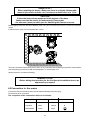
The fixture is rated to IP65 and may be mounted in any orientation without altering its operation characteristics
(see the drawing).The fixture's head can be adjusted in a vertical range 130°.
Allow the fixture to cool before handling!
DANGER TO LIFE!
Before taking into operation for the first time,the installation has to be
approved by an expert!
4.5Connection to the mains
Connect the fixture to the mains with the protected and weatherproof power-plug.
The earth has to be connected!
The occupation of the connection-cables is as follows:
Cable (EU)
Cable (US)
Pin
Brown
Black
Live
L
Light blue
White
Neutral
N
Yellow/Green
Green
Earth
10
International
4.6 DMX- 512 connection, master/slave connection
Controller operation
Master/slave operation
The wires must not come into contact with each other, otherwise
the fixtures will not work at all, or will not work properly.
Only use a RS-485 data cable and 3-pin XLR connectors in order to connect the controller with the fixture or one
fixture with another.The connectors must be protected in a weatherproof housing.
Occupation of the XLR-connection:
DMX - output
DMX-input
XLR mounting-socket:
XLR mounting-plug:
1 - Ground
2 - Signal (-)
3 - Signal (+)
1 - Ground
2 - Signal (-)
3 - Signal (+)
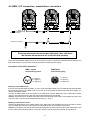
Building a serial DMX-chain:
If you are using the standard controllers, you can connect the DMX-output of the controller directly with the DMXinput of the first fixture in the DMX-chain. If you wish to connect DMX-controllers with other XLR-outputs, you
need to use adapter-cables.
Connect the DMX-output of the first fixture in the DMX-chain with the DMX-input of the next fixture. Always
connect output with the input of the next fixture until all fixtures are connected.
Caution: At the last fixture, the DMX-cable has to be terminated with a terminator. A termination plug is an XLR
connector with a 120 ohm resistor soldered across pins (+) and (–).
Building a master/slave-chain:
Connect the DMX-output of the master fixture in the data-chain with the DMX-input of the first slave. Always
connect output with the input of the next slave until all slaves are connected (up to 9 fixtures).
Caution:It’s necessary to insert the XLR termination plug (with 120 Ohm) into the input of the master fixture and
into the output of the last slave fixture in the link in order to ensure proper transmission on the data link.
11
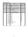
5. DMX Protocol-8 bit
Channel
Value
1
Function
Type of control
0-255
Cyan
Cyan from 0 (white) to 255 (full cyan)
proportional
0-255
Magenta
Magenta from 0 (white) to 255 (full magenta)
proportional
0-255
Yellow
Yellow from 0 (white) to 255 (full yellow)
proportional
0-255
Dimmer intensity
Intensity from 0 to 100%
proportional
0-255
Speed of CMY and dimmer
From max. speed to min. speed
proportional
2
3
4
5
6
0-7
8-15
16-23
24-31
32-39
40-47
48-55
56-63
64-71
72-79
80-87
88-95
96-103
104-111
112-119
120-127
128-139
140-229
230-239
240-255
Colour macros,Lamp On/Off,Reset
Off
Macro 1
Macro 2
Macro 3
Macro 4
Macro 5
Macro 6
Macro 7
Macro 8
Macro 9
Macro 10
Macro 11
Macro 12
Macro 13
Macro 14
Macro 15
Lamp On after 3 sec.,reset
No function
Lamp Off after 3 sec
No function
12
step
step
step
step
step
step
step
step
step
step
step
step
step
step
step
step
6.Control of the fixture
The ECOLOR 250 XT is controled by infra-red 6-buttons remote control and 4-digit LED display on the rear side
of the fixture. You can simply set the lighting address,operating mode, read the number of the lamp or unit hours,
switch On and Off the lamp, run programs, make a reset and also use special functions for manual and service
purposes.
Two LEDs on the rear panel display the fixture status. Red LED indicates normal operation after switching the
fixture on.Green LED indicates the lamp is switched on.
Green LED
Red LED
The red LED on the remote control indicates if any button is pressed (the signal is transmited).
There are the 2 buttons on the remote control which have a special function:[Power]-button and [Blackout/lamp
Off]-button.
Power- switching the lamp On
Red LED
Blackout/lamp Off- brief press makes the blackout
- long press makes the lamp Off
The ECOLOR 250 XT can be operated with a controller in controller mode or without the controller in standalone mode.
Both modes are described in the texts below.
7.Controller mode
The fixtures are individually addressed (001-507) on a data link and connected to the controller.The fixtures respond
to the DMX signal from the controller.
7.1 DMX addressing
The remote control allows you to assign the DMX fixture address, which is defined as the first channel from which
the ECOLOR 250 XT will respond to the controller.
If you set, for example, the address to channel 5, the ECOLOR 250 XT will use the channel 5 to 10 for control.
Please, be sure that you don’t have any overlapping channels in order to control each ECOLOR 250 XT correctly
and independently from any other fixture on the DMX data link.
If two, three or more ECOLOR 250 XT are addressed similarly, they will work similarly.
For address setting, please refer to the instructions under "Addressing"(menu "A001").
Controlling:
After having addressed all ECOLOR 250 XT , you may now start operating these via your lighting controller.
Note:After switching on, the ECOLOR 250 XT will automatically detect whether DMX 512 data is received or
not.If there is no data received at the DMX-input, the display will start to flash "A001" with actually set address.
This situation can occur if:
- the 3 PIN XLR plug (cable with DMX signal from controller) is not connected with the input of the ECOLOR 250
XT
- the controller is switched off or defective, the cable or connector is defective or the signal wires are swap in the
input connector.
Note:It’s necessary to insert the XLR termination plug (with 120 Ohm) to the last fixture in the link in order to
ensure proper transmission on the DMX data link.
7.2 Remotely and manually controllable functions
Lamp
The ECOLOR 250 XT is to be operated with a MSD/HSD 250 or MSD 250/2 lamp.
A relay inside of the ECOLOR 250 XT allows you to switch on and off the lamp via the remote control or via your
DMX-controller without affecting the rest of the lighting.
To switch On/Off the lamp,use the [Power]-button or [Blackout/lamp Off]-button on the remote control .You can
use also menu "LAMP"- please refer to "Switching On/Off the lamp ".
Note: It is also important to note, that the discharge lamp is cold restrike types, that means, that they have to be
cold before re-striking. For this reason, you have to wait 5 minutes (after having switched Off the lamp before you
can switch it back On again. If you try to switch On the lamp within 5 minutes after having switched it Off, the
ECOLOR 250 XT will store this information and automatically ignite the lamp when the 5 minutes period has
expired. The message "HEAt" will appear on the control board display of the ECOLOR 250 XT. If the ignition of
the lamp is seven times unsuccessful, on the display will appear "LA.Er.", meaning that the lamp could be
damaged or even missed, or there could be a failure on the ignitor or ballast.
Avoid turning on several lamps at once.
CMY-colors mixing system
The CMY color mixing system is based on graduated cyan,magenta and yellow color filters.A continuous range
of colours may be achived by varying the amount of each filter from 0 to 100%
Dimmer
Smooth 0-100% dimming is provided by the special dimmer unit.
Beam effects
Horizontal and vertical beam shapers – manually adjustable.Frost filter for softer beam and colour temperature
correction filter 3200K – manually adjustable.
Clock
The ECOLOR 250 XT has a battery operated 24-hour clock that can set the start and the stop stand-alone
operation.
Cooling
The ECOLOR 250 XT is cooled by one axial fan in the head.
8. Stand - alone mode
The fixtures on a data link are not connected to the controller but can execute pre-set programs which can be
different for every fixture.To set the program to be played,see the "Stand-alone setting" ( menu "St.AL.").
"Stand-alone operation" can be applied to the single fixture (the fixture may be set to the master /slave mode ) or
to multiple fixtures operating synchronously.
Synchronous operation of multiple fixtures requires that they must be connected on a data link and one of them
is set as a master (master mode) and the rest as the slaves (slave mode).The slaves are assigned to SLA.1SLA.9 and on the certain slave address can be connected only one fixture.To set the fixture as the master or
slave , see the "Addressing" (menu "A001").
If the master fixture runs a reset,switches On/Off the lamp or plays test(program) ,all slaves will execute
these acts too (e.g. if the master fixture has switched its lamp off,no slave can switch its lamp on)!
You can't play or edit any programs on the slaves by their control displays if the master is switched on
and connected to the master/slave chain.
14
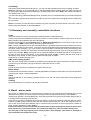
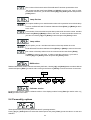
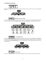
The master fixture starts simultaneous program start in the other slave fixtures.All fixtures have a definite, synchronized
starting point when playing back their programs.The number of running program is the same in all slaves and
depends on the master's choice (menu "St.AL." ).Every fixture runs its program repeatedly ,starting the program
step No.1 when requested by the master .
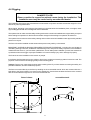
For example:
If the slave fixture has a shorter program length, it will continously repeat its program until the master fixture
finishes its own program and restarts its program running (slave 1- prog.step 3 will not be finished).
If the slave fixture has a longer program length, it will restart at prog. step 1 before it completes all its prog.steps
(slave 2 - prog.step 5 will not be played)- see the picture bellow.
Restart
Starting point
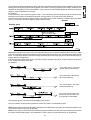
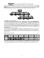
Stand-alone operation can be set for one or two periods during a 24 hour period,using the built-in clock or for a light
level,using the built-in light sensor.If both the clock and the light sensor are active, operation starts within the set
times or if it is darker than the light-level setting.Operation stops at the stop times or if that the ambient light is
brighter than the set light level.
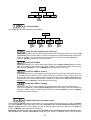
If the time periods overlap each other or if the time period overlaps the light level period,the fixture will respond
to the events according to their rank.
For example:
All events will be executed
(Start1,Stop1,Start2,Stop 2).
The events Start 1 and Stop 2
will be executed only.
The events Start 1 and Stop
will be executed only.
The Time period1 and Light
period will be executed ,the
Time period 2 is eliminated.
The played program is the same for all time(light level) periods.
From the master's control panel is possible to control any slave in a master/slave chain.
Note:Disconect the fixtures from the DMX controller before master/slave operating ,otherwise data collisions can
occur and the fixtures will not work properly!
Note:It’s necessary to insert the XLR termination plug (with 120 Ohm) into the input of the master fixture and into
the output of the last slave fixture in the data link in order to ensure proper transmission on the data link.
15
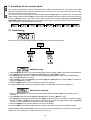
9. Functions of the control panel
The control panel situated on the front side of the base offers several features. You can simply set the DMX
address,master/slave mode, read the number of lamp or unit hours, run test, make a reset and also use many
functions for setting and service purposes.
The main menu of the control panel is accessed by pressing the [ Mode ] button - press this one so many times
until the display shows message "A001" (with actually stored address). Browse through the menu by the pressing
[ Up ] or [ Down ] buttons - the display shows step by step these messages: A001,SLCt, InFO,PErS,tESt,
StAL,rESE, SPEC. Press [ Enter ] if you wish to select one of them. The functions are described in the following
sections and the function hierarchy is shown below.
9.1 Addressing
By this menu you can set the DMX address or address the fixture as a master/slave.
- DMX addressing
1. Press the [Mode]- button so many times until the display shows message "A001" (with actually stored address).
2. Press [Enter]-button and use the [Up] and [down] buttons to select"dM.Ad."-menu.
3. Press[Enter]-button(the letter "A" flashes) and by [Up] and [down] buttons select required address (001 507), press [Enter]-button to confirm.
4. Select "MA.SL."-menu,press[Enter]-button and use [Up] and [down] buttons to select "d.AbL."(no master or
slave),press [Enter] to confirm.
5. Press the [Mode]- button.Choosen address is shown on the display.
If message "A001" (with actually stored address) flashes-no DMX data received at the DMX-input.
- Master/slave adressing
1. Press the [Mode] button so many times until the display shows message "A001" (with actually stored
address).
2. Press [Enter]-button and use the [Up] and [down] buttons to select "MA.SL."-menu.
3. Press[Enter]-button(display flashes) and select"MASt."(to set the fixture as the master in a chain of multiple
fixtures) or "SLA.1"-"SLA.9" (to set the fixture to be the slave in a chain of multiple fixtures) and press [Enter]
to confirm. If you want address no master or slave, select "d.AbL.".
4. Press the [Mode]- button.Chosen address is shown on the display.
If message "MASt." fast flashes- DMX signal is received at the DMX-input.Disconnect DMX controller!
Only one fixture may be the master. Up to the 9 slaves may be connected to the master and on the certain
address can be connected only one slave fixture (SLA.1-SLA.9).
16
Note:Disconect the fixtures from the DMX controller before master/slave operating ,otherwise data collisions can
occur and the fixtures will not work properly!
If the fixture is set as the master and DMX signal is connected to its input,the error massage "MAEr" will appear
on its display and the fixture's address will be set to its DMX address in order to respond to DMX signal from the
controller.
For example:
The master fixture has this address setting:"dM.Ad."-menu.........A013
"MA.SL."-menu........MASt (is displayed)
The DMX signal is connected to the master fixture.The message "MAst" starts fast flashing and after 20s error
massage "MA.Er" appears on its display and the fixture automatically will be switched to its DMX address
(master address is disabled).
Now the fixture has the address setting: "dM.Ad."-menu.........A013 ("A013"/" MA.Er"blinks )
"MA.SL."-menu.........d.AbL.
If the fixture is set as the slave and DMX signal is connected to its input,the fixture will respond to DMX signal
from the controller (in dependence on the fixture's DMX address).
9.2 Slave control
This function allows you to control the slaves from the master's control panel in a master/slave operation.
Select this function from the main menu and press [ Enter ]-button.Browse the list of all connected slaves
("SL.C.1" - "SL.C.9") by pressing [ Up ] and [ Down ] bottons.Select the desired slave and press [ Enter ]button.The slave's control panel is available from the master's control panel.
If no slave is connected to the master,massages "SL.C.1","SL.C.2","SL.C3"..."SL.C.9" still round repeat.
Note:This function is available from the master fixture only.
9.3 Fixture informations
The menu allows you to read an useful information about the fixture as the lamp life,lamp strikes,software
version, etc.
Press [ Up ] or [ Down ] buttons to select the desired option and press [ Enter ] to see the value or next submenu.
Power On time
-By this option you can read the total number of the operation hours since the
ECOLOR 250 XT has been fabricated. Press [ Enter ] or [ Mode ] to return to the
menu.
17
- The number of the hours that the ECOLOR 250 XT has been powered On since
the counter was last reset.Press [ Enter ] or [ Mode ] to return to the menu.In order
to reset this counter to 0, you have to hold the [ Up ] and [ Down ]-button and press the
[ Enter]-button.
Lamp On time
- This option enables you to read the total number of the operation hours with the lamp
on since the ECOLOR 250 XT has been fabricated.Press [Enter ] or [ Mode ] to return
to the menu.
- The number of hours that the lamp has been powered On since the counter was last
reset.Press [Enter] or [Mode] to return to the menu. In order to reset this counter to 0,
you have to hold the [ Up ] and [ Down ]-button and press the [ Enter ]-button.
Lamp strikes
- By this option you can read the total number of the lamp strikes since the
ECOLOR 250 XT has been fabricated.Press [Enter ] or [Mode ] to return to the menu.
-The number of the lamp strikes since the counter was last reset.Press [ Enter]
or [ Mode ] to return to the menu. In order to reset the counter to 0, you have to
hold the [ Up ] and [ Down ]-button and press the [ Enter ]-button.
- DMX values
Readout DMX values of each channel received by the fixture. Use the [ Up ] and [Down] buttons to select desired
channel and press [ Enter ] to read its value coming to the fixture or [ Mode ] to cancel and return to the menu.
- Software version
By this function you can read the software version of the display module. Press [ Enter ] to read its value or [
Mode ] to return to the menu.
9.4 Personality options
These options allow you to modify ECOLOR 250 XT operating behavior.
Press [ Up ] or [ Down ]buttons to select the desired option and press [ Enter ] to set the value or to see next
submenu.
18
Lamp presetting
This function allows you to adjust the lamp settings:
Lamp On after switching the fixture On
This function enables to turn the lamp on automatically after switching the fixture on. Use the [Up]
and [Down] buttons to select "On" if you wish to turn the lamp on automatically after switching the
fixture on or "Off" if you wish the lamp off after switching on the fixture and press [Enter] to
confirm or [Mode] to cancel and return to the menu.
Lamp Off via DMX
This function allows you to switch off the lamp by DMX. Use the [Up] and [Down] buttons to select
"On" if you want to switch off the lamp by DMX or "Off" if you don’t want to switch off the lamp by
DMX and press [Enter] to confirm or [Mode] to cancel and return to the menu.
Lamp On if DMX is present
This function allows you to strike the lamp automatically after 26 seconds if DMX signal is present
on the data link.If the ignition is unsuccessfull (e.g.lamp is too hot),the fixture will try to ignite the
lamp after next 26 s.This process will repeat until the lamp lights.Use the [Up] and [Down] buttons
to select "On" if you want to strike the lamp or "Off" if you don’t want to strike the lamp and press
[Enter] to confirm or [Mode] to cancel and return to the menu.
Lamp Off if DMX is missing
This function allows you to switch Off the lamp automatically after 2 minutes if DMX signal is
missing on the data link. Use the [Up] and [Down] buttons to select "On" if you want to switch Off
the lamp or "Off" if you don’t want to switch Off the lamp and press [Enter] to confirm or [Mode]
to cancel and return to the menu.
Switch On/Off the lamp light sensor
Use the [Up] and [Down] buttons to select "On" if you wish to switch the lamp light sensor on and press [Enter]
to confirm or [Mode] to cancel and return to the menu.The option"On" is for the standard operation.Use the
[Up] and [Down] buttons to select "Off" if you wish to switch the lamp light sensor Off and press [Enter] to
confirm or [Mode] to cancel and return to the menu.
Important: The option"Off" is for "emergency operation" only if the lamp light sensor is defective and
you will wait for a service intervertion! If the lamp light sensor is switched Off,the error messages
19
"LAEr,SnEr,HEAt" will not appear on the display (only the message "HEAt" will appear if the lamp was turned off
and on within 5 minutes ) and at switching the lamp on the electronics will still try to ignite the lamp until it shines
(even when the lamp is damaged or absent), on this account some electronics parts could be damaged!
- Display adjusting
This function allows you to adjust the display settings:
- Display -intensity
With this function you can adjust the display intensity from 20% to 100% . Use the [Up ] or [Down
] buttons to select the level of the display intensity and press [Enter ] to confirm or [Mode ] to
cancel and return to the menu.
- Display-reverse
With this function, you can rotate the display by 180°. Use the [Up ] or [Down ] buttons to select
"normal display" or "display turned by 180°" and press [Enter ] to confirm or [Mode ] to cancel and
return to the menu.
- Display-On
This function allows you to keep the display on or to turn off automatically 2 minutes after last
pressing any button on the control panel. Use the [Up ] or [Down ] buttons to select "On" if you wish
to keep the display on or "Off" if you wish to turn off automatically 2 minutes after last pressing any
button on the control panel and press [Enter ] to confirm or [Mode ] to cancel and return to the
menu.
20
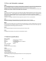
- Default settings
Press [ Enter ] to reset all fixture personalities (not the adjusting functions) to the default values. On the display
will appear "rSt" meaning that the fixture makes the reset. See the table of personality setting and their default
positions.
Personality
Display
Default values
(SHADED)
Lamp On after switch.
the fixture On
Lamp Off via DMX
Lamp On if DMX
is present
Lamp Off if DMX
is missing
Display-On
Display intensity
Display- reverse
Presetting playback
Light level-start
Light level-stop
Timer 1-start
Timer 1-stop
Timer 2-start
Timer 2-stop
Switch On/Off
the lamp light sensor
9.5 Switching On/Off the lamp
Press the [Mode] button in order to access the main menu. Browse through the menu by pressing the [Up] and
[Down] buttons until the display shows "LAMP". Confirm by pressing [Enter] button.
Use the [Up] and [Down] buttons to select "On" to switch On the lamp and "Off" to switch Off the lamp and
press [Enter] to confirm or [Mode] to cancel.
9.6 Test sequences
This function allows you to run a special demo-test sequences without an external controller, which will show you
21
some possibilities of using ECOLOR 250 XT and is a good for an introduction of the fixture.
Browse through the menu by pressing the [Up] and [Down] buttons until the display shows "tESt". Confirm by
pressing [Enter] button in order to run the test program.
If you want to pause the runnnig program in the required position, press the [Enter]-button(messages"PAUS./
test." blink ).To continue the program running,press the [Enter]-button again.
9.7 Stand-alone setting
This menu offers options for stand-alone mode as a program playing ,programming and modifying current
programs.You can run programs at pre-defined two periods during a 24 hour period or at a certain light level.
-Presetting playback
This function allows you to select the the program which will be played in the stand-alone mode after switching
the fixture on( LAAu-function must be "On" in the menu LAPr) .The selected program will be also used for the
operating with the time periods or the light level period( LAAu-function must be "OFF" in the menu LAPr).
Use the [Up] and [Down] buttons to select desired program ("tESt"- bilt-in program) or "OFF" if you don't want to
trigger any program and press [Enter] to confirm or [Mode] to cancel and return to the menu.Selected program
will be played continuously in a loop as long as it appears on the display.
This option should be set "OFF" for all slaves in the master/slave chain by reason of the right program starts.
For example: You have selected program "PrG.3" in this menu and:
This fixture is set as a single fixture (master/slave or controller operating)- the fixture will run its program "PrG.3".
This fixture is set as a master in a data chain- the fixture will run its program "PrG.3".
This fixture is set as a slave in a data chain- the fixture will run its program according to the master(if the master
runs its own program "PrG.1", the slave will run its own program "PrG.1"also).
Note for the controller mode: If the fixture operates in this mode ( DMX controller is connected) and any
program from this menu is selected ,the fixture will start to play the selected program if:
- the fixture is switched on
- the reset command from DMX controller is received
- the timer or light level trigger are active and starts the operation
In all these cases the fixture not respond to the DMX controller.
- Timer
By this menu you can set one or two periods during a 24 hour time period for the stand-alone operation.For
example ,one period in the morning and one period in the evening.
22
-Fixture clock
This function allows to set the current fixture time. Use the [Up] or [Down] buttons to set the
hour and press the [Enter]-button.Use the [Up] or [Down] buttons to set the minutes and press the
[Enter]-button to save the adjusted time or press the [Mode]-button twice to cancel and return
to the menu.
.
-Timer 1 -start
This function sets the start of the time period 1.Use the [Up] or [Down] buttons to specify the
start hour and press the [Enter]-button.Use the [Up] or [Down] buttons to specify the start minute
and press [Enter].
-Timer 1-stop
This function sets the finish of the time period 1.Use the [Up] or [Down] buttons to specify the
stop hour and press the [Enter]-button.Use the [Up] or [Down] buttons to specify the stop minute
and press [Enter].
If you wish to deactivate the Timer 1,set Ont1="Off" and OFt1="Off".
-Timer 2 -start
This function sets the start of the time period 2.Use the [Up] or [Down] buttons to specify the
start hour and press the [Enter]-button.Use the [Up] or [Down] buttons to specify the start minute
and press [Enter].
-Timer 2-stop
This function sets the finish of the time period 2.Use the [Up] or [Down] buttons to specify the
stop hour and press the [Enter]-button.Use the [Up] or [Down] buttons to specify the stop minute
and press [Enter].
If you wish to deactivate the Timer 2,set Ont2 ="Off" and OFt2 ="Off".
Note:Please, be sure that you don’t have any overlapping time periods to ensure the correct operation.
Don´t forget to choose the program which will be playing when the fixture operates (menu Auto).
If you want to modify the fixture clock or the time limits,do it when the program is not runnig,otherwise the
current time period will not be finished correctly.
How to set the time period operation:
1.Set LAAu-function to "Off"(menu PerS,submenu LAPr) .
2.Set the timer 1 and timer 2 (menu StAL,submenu timr).
If you will use only one time period for operations,deactivate the timer 2.
3.Choose the desired running program (menu StAL,submenu Auto).
4.Deactivate the light level trigger (menu StAL,submenu LiGt).
23
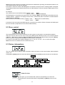
- Light level trigger
By this menu you can set a light level for the stand- alone operation.If the light intensity falls below the specified
level then operation will start.
-Scanning the ambient light level
Press the [Enter] button to scan the current ambient light level (2-darkest,252-brightest).This value
is useful as a comparative level for setting both start and stop light levels for operation in the standalone mode . The scanning takes about 7 seconds.By pressing the [Mode]- button you can return
to the menu.
-Light level - start
Use the [Up] and [Down] buttons to select the required light level when the operation is to be
started(3-251) and press [Enter] to confirm or [Mode] to cancel and return to the menu.Don´t forget
to choose the program which will be playing when the fixture operates (menu "Auto").
Important:The values 0,1,2,252,253,254,255 do not affect the state of the fixture.
-Light level -stop
Use the [Up] and [Down] buttons to select the required light level when the operation is to be
finished (3-251) and press [Enter] to confirm or [Mode] to cancel and return to the menu.
Important:The values 0,1,2,252,253,254,255 do not affect the state of the fixture.
If you wish to deactivate the light level trigger,set the "OnL"= 0 and "OFFL"= 255.
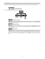
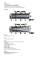
Example of the light level operation:
How to set the light level operation:
1.Set LAAu-function to "Off"(menu PerS,submenu LAPr) .
2.Set the start and stop light levels for fixture operating (menu StAL,submenu LiGt).
3.Choose the desired running program (menu StAL,submenu Auto).
4.Deactivate the timer 1 and timer 2 (menu StAL,submenu timr).
Note:The light sensor has the 2 minutes delay for the start/stop of the light level operation to eliminate the random
light fluctuations.If the fixture is placed close to the changeable ambient illumination (e.g.neon signs),the time
period for stand-along operation may be useful than the light level setting.
24
- Playing program
This function allows you to run a bilt-in program "tESt" and the 3 freely-programmable programs "PrG.1,PrG.2,PrG.3"
.Press [ Up ] or [ Down ] buttons to select the desired program and press [Enter ] to run the program which will
be played continuously in a loop.
If you want to pause the runnnig program in the required position, press the [Enter ]-button(messages"PAUS"/"
program No."blink ).To continue the program running,press the [ Enter ]-button again.
Note:If the fixture operates in the controller mode ( DMX controller is connected) and any program from this
function is selected in this case the fixture will not respond to the DMX controller and will play selected program.
You can't play programs on the slave fixtures from their control panels if the master fixture is switched On and
connected to the slaves (playing is forced by the master).
- Editing program
This menu item allows you to select a program to edit or create.The ECOLOR 250 XT has one built-in program
("tESt") and the 3 free programs,each up to 99 steps.Each program step has a dynamic part(fade time) and
static part(step time).
Fade time-the time,during which effects move to the programmed position.
Step time-the time,during which effects last in the current step.
If the fixture is set as a master ,then you may edit any program in the slaves.You can't edit programs on the slave
fixtures from their control panels if the master fixture is switched on and connected to the slaves (editing is
possible by the master control panel only).
Procedure:
1. Press [ Up ] or [ Down ]-button to select the program you want to edit ("PrG.1" - "PrG.3") and press [ Enter ].
2. Press [ Up ] or [ Down ]-button to select the desired fixture ("MASt." - "SLA.9") and press [ Enter ]-button.
3. Press [ Up ] or [ Down ]-button to select the desired program step ("St.01" - "St.99") and press [Enter ]-button.
4 Press [ Up ] or [ Down ]-button to select the desired item and press [ Enter ]-button.Now you can edit by [Up
] or [ Down ] buttons the DMX value for selected item:
"P.End." - a total number of the program steps,value 1-99 .This value you must set before start
programming(e.g. if you want to create program with the 10 steps,set the value onto 10).
"CYAn" - a cyan,value 0-255
"MAGE" - a magenta,value 0-255
"YELL" - a yellow, value 0-255
"dimr" - a dimmer intensity,value 0-255
"SPEd" - a speed of CMY and dimmer,value 0-255
"Func" - a colour macros,switch On/Off the lamp,value 0-255
"S.tim." - a step time,value 0,1-25,5 seconds
"COPY." - a copying the current prog. step to the next prog. step .If the last prog.step is copied to the
next prog. step ,parameter "P.End" is increased about 1 automatically (except step 99).
5. Press [ Enter ]-button to confirm adjusted value .
6. Press [ Mode ]-button,select next prog. step and repeat this procedure (steps 4 and 6).
The editting programs "PrG.1,PrG.2,PrG.3" are saved in the current modified fixture (master or slave1-9).
9.8 Reset function
Press [ ] button to run a reset. This option enables the ECOLOR 250 XT to index all effects (functions) and return
to their standard positions.
25
9.9 Special functions
Use the [Up ] or [ Down ] buttons to browse through the special functions and select the one by pressing [ Enter
]-button.
- Manual control of effects
The function allows you to control manually the channel functions of the fixture. Use the [ Up ] or [ Down ] buttons
to select desired function and press [Enter ] to adjust the effect or [ Mode] to cancel and return to the menu.
- Lamp adjustment
This function can be used when you make the fine adjustment of the lamp.If you select "LAAd" pressing by [Enter
]-button ,all effects will be canceled,shutter will be opened and the dimmer intensity will be set onto 100%.By
using the options "CYAn, MAGE,YELL,dimr" you can focus the light on a flat surface (wall) and perform the fine
lamp adjustment.
-- Fixture code
The option contains identification code (1-9999) for the fixture, which is used for the master/slave operation.
26
- Adjusting the default positions of the CMY wheels
By this function you can adjust the colour wheels and the dimmer unit to their right positions. Use the [Up] and
[Down] buttons to browse through the adjusting menu - the display shows step by step these messages: "CYAn,
MAGE,YELL,dimr" by which you can adjust the effects to the required positions (0-255) before the function
calibration.Then when the positioning is finished use the last "FCAL" function (Fixture calibration).
1. Calibration via the control board
Press [Enter] and the [Up] and [Down] buttons in order to display the following messages: "CYAn, MAGE,YELL,"
for very smooth function calibration. Select one of them, press [Enter] and use the [Up] and [Down] buttons in
order to adjust their right value from 0 to 255. Then press [Enter] to confirm or [Mode] to cancel and return to the
menu. This can be repeated for each calibration parameter if it is required. When the calibration is finished, it is
necessary to use the "A.rES." function in order to write the calibration values to the memory (EPROM) and to
make a reset in order to check the newly adjusted positions of the CMY-colours. When the reset of the fixture is
finished, the display will show the "F.CAL." message. Press [Enter] to repeat the calibration or [Mode] to return
to the "AdJ" menu.
2. Calibration via the external controller
Connect the DMX controller to the fixture.Press [Enter] and the [Up] and [Down] buttons in order to display the
following messages: "CYAn, MAGE,YELL" - calibration parameters. Select one of them and press [Enter].
Now you can calibrate the CMY-colours by your controller. The DMX calibration protocol is described in the table
mentioned below.
DMX Calibration protocol:
After having calibrated required functions press [Enter] to confirm (or [Mode] to cancel and return to the menu
without reset by the "A.rES." function) and use the "A.rES." function in order to write the calibration values to the
memory (EEPROM) and to make a reset in order to check the new adjusted positions of the CMY-colours .
27
10. Error and information messages
HEAt
This message appears if you try to switch on the lamp within 5 minutes after having switched it off (the lamp is too
hot). The message will appear on the display if the lamp doesn't ignite within 15 seconds. The ECOLOR 250 XT will
store this information and automatically ignite the lamp when the 5 minutes period has expired.
Caution: The message is disabled if the lamp light sensor (function "En.Sn.") is switched Off (only if the lamp was
turned Off and On within 5 minutes,the message "HEAt" will appear).
LA.Er.
The ignition of the lamp is seven times unsuccessful (the HEAt message appeared six times before), and the
display shows "LA.Er.", meaning that the lamp could be damaged or even missed, the fixture is overheating (this
can occur if the ambient temperature is 45° C or more) or there could be a failure on the ignitor or ballast.
Please place or replace the lamp, check the ambient temperature or contact your dealer if the situation was not
caused by the lamp.
Caution: The message is disabled if the lamp light sensor (function "En.Sn.") is switched Off.
SnEr.
This message appears if the lamp lighting sensor is failed. Please, contact your dealer.
Caution: The message is disabled if the lamp light sensor (function "En.Sn.") is switched Off.
MA.Er
(Master error)The message informs you that the fixture was addressed as a master and DMX signal is connected
to its input.Disconnect the DMX controller from fixture's input and address the fixture as the master again.The
message appears after switching the fixture Off and On.
Po.Er.
This message will appear if the fixture was shortly disconnect from the main.
Fr.Er.
It will appear if the frequency of the mains is not standard 50 or 60Hz.
11.Technical specifications
Power supply:
EU-model:
Fuse:
US-model:
Fuse:
Power consumption:
208/230/240V AC, 50/60Hz ~
T 3.15A @ 230V
100/120/208/230/240 V AC, 50/60Hz ~
T 6,3A @ 120V
450 VA
Remote control:
2 batteries 1,5V ,size AAA,LR03(T)
Lamp:
MSD/HSD 250 GY-9,5
Optical System:
-150mm Fresnel lens
·Manually adjustable zoom 8 - 22°
·High reflectivity computer designed eliptical reflector for maximum lighting output
Colours:
-CMY - colours mixing system
28
Effects:
-15 colour macros
-Horizontal beam shaper – manually adjustable
-Vertical beam shaper – manually adjustable
-Frost filter for softer/wide beam – manually adjustable
-Colour temperature correction filter 3200K – manually adjustable
Beampath:
Dimmer:
- Smooth dimmer from 0 - 100 %
Fan:
- Axial fan in the fixture head
Motor:
- 4 high-quality stepping motors controlled by microprocessors
Electronics:
- Digital serial input DMX-512
- 6 control-channels (8 bit protocol):
Channel 1: Cyan
Channel 2: Magenta
Channel 3:Yellow
Channel 4: Dimmer intensity
Channel 5: Speed of CMY and dimmer
Channel 6: Colour macros,Switching On/Off the lamp
Rigging:
Mounts horizontally or vertically with 2 crews
Vertical head adjusting range: 130°
Protection factor IP 65
29
Temperatures:
Maximum ambient temperature ta: 35° C
Maximum housing temperature tB (steady state): 110° C
Minimum distances:
Min.distance from flammable surfaces: 1,0m
Min.distance to lighted object: 1,0m
Dimensions and weight:
Length : 330 mm
Width: 295 mm
Height (head horizontally): 450 mm
Weight (net): 22 kg
Shipping weight: 28 kg
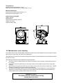
12. Maintenance and cleaning
The operator has to make sure that safety-relating and machine-technical installations are inspected by an expert
after every four years in the course of an acceptance test.
The operator has to make sure that safety-relating and machine-technical installations are inspected by a skilled
person once a year.
The following points have to be considered during the inspection:
1)
All screws used for installing the devices or parts of the device have to be tighly connected and must not
be corroded.
2)
There must not be any deformations on housings, fixations and installation spots (ceiling, suspension,
trussing).
3)
Mechanically moved parts like axles, eyes and others must not show any traces of wearing (e.g. material
abrading or damages) and must not rotate with unbalances.
4)
The electric power supply cables must not show any damages, material fatigue (e.g. porous cables) or
sediments. Further instructions depending on the installation spot and usage have to be adhered by a
skilled installer and any safety problems have to be removed.
DANGER TO LIFE !
Disconnect from the mains before starting
maintenance operation!
30
Regular cleaning will not only ensure the maximum light-output, but will also allow the fixture to function reliably
throughout its life.
Rinse off loose dirt with a garden hose or low pressure water spray.Wash the housing with a soft brush or sponge
and a mild, non-abrasive washing detergent.Rinse it.
There are no serviceable parts inside the device except for the lamp and the batteries inside the remote control.
Maintenance and service operations are only to be carried out by authorized dealers.
Please refer to the instructions under "Fitting/Exchanging the lamp".
Should you need any spare parts, please use genuine parts.
If the power supply cable of this device will be damaged (cable firmly connected with the device), it has to be
replaced by authorized dealers only in order to avoid hazards.
If the power supply cable of this device will be damaged (replaceable cable), it has to be replaced by a special
power supply cable available at your dealer.
Should you have further questions, please contact your dealer.
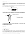
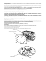
Replacing the main fuse
The fixture contains 3 fuses located on the circuit board.The main fuse is placed in the fuseholder next to the
relay on the circuit board and has marking F10(see the picture below).If the lamp burns out, the fine-wire fuse of
the device might fuse, too. Only replace the fuse by a fuse of the same type and rating .
Before replacing the fuse, unplug mains lead!
The fuse replacement should be carried out by authorized persons only.
Procedure:
Step 1: Open the plate cover of the base by loosening the 12 screws and remove the rubber seal.
Step 2: Remove the old fuse from the fuseholder.
Step 3: Install the new fuse in the fuseholder.
Step 4: Reinsert the seal and the plate cover of the base and tighten the screws.
Rubber seal
Plate cover of the base
Main fuse F10
Relay
31
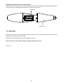
Replacing the batteries in the remote control
Pull off the botton cover of the remote control and take the batteries out .Replace the exhausted batteries with a
new ones-check the voltage and the polarity!Push the bottom cover in back.
batteries
bottom cover
13. Appendix
We hope you will enjoy your ECOLOR 250 XT. We can assure you that you will enjoy this device for years if you
follow the instructions given in this manual.
Should you have further questions, do not hesitate to contact us.
Please note: Every information is subject to change without prior notice.
Version 1.0
32