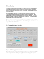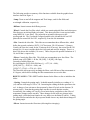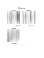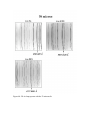
1
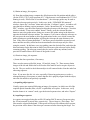
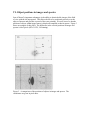
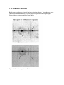
Manchester Echelle Spectrometer ( MES – SPM ) MEZCAL User’s Manual Version 1.1 December 2003 José Alberto López, Michael Richer Leonel Gutiérrez, John Meaburn & Hortensia Riesgo Mezcal documentation Other information available for the Mezcal spectrograph includes: I – Manchester Echelle Spectrometer, (MES-SPM) MEZCAL. Manual de Usuario. Versión 1.1, Diciembre, 2003. J. A. López, Michael Richer, Leonel Gutiérrez y Hortensia Riesgo. This is the Spanish version of this manual. II - MEZCAL: Un espectrógrafo computarizado para su uso en el Observatorio Astronómico Nacional. L. Gutiérrez, J. M. Murillo, F. Quiróz, M. H. Pedrayes, J. A. López & J. Meaburn. Reporte Técnico OAN. Describes the operation of the graphical interface, including the use of macros. III - Upgraded control, acquisition program and user interface for the Manchester Echelle at San Pedro Mártir. L. Gutiérrez, J. M. Murillo, F. Quiróz, M. H. Pedrayes, J. Meaburn & J. A. López. Proceedings SPIE on Advanced Telescopes and Instrumentation Control Software II, vol. 4848, p. 531. Describes the modifications made to the spectrograph in 2000. It includes a description of the user interface. IV – The efficiency, stability, and lamp identifications for the MES-SPM spectrograph. Michael Richer. August 2003. http://haro.astrossp.unam.mx/Instruments/mezcal/efmez_e.htm Describes the efficiency of the spectrograph as well as its spectral stability and provides identifications for the ThAr lamp. V - The Manchester Echelle Spectrometer at the San Pedro Mártir Observatory (MESSPM). J. Meaburn, J.A. López, L. Gutiérrez, F. Quiróz, J. M. Murillo, J. Valdéz & M. Pedrayes. 2003, Revista Mexicana de Astronomía y Astrofísica, 39, 185. Describes the general use of the instrument and the classes of astrophysical problems it was designed to confront efficiently. VI – Ten years of Manchester Echelle Spectrometers J. Meaburn & M. Bryce. 1993, Optics in Astronomy, 32nd Herstmonceux Conference, p.9. A general description of the MES spectrograph. VII- A dedicated echelle spectrometer for the Anglo-Australian telescope. J. Meaburn, B. Blundell, R. Carling, D.F. Gregory, D. Keir & C. G. Wynne, 1984, Monthly Notices of the Royal astron. Soc. 210, 463. The original article describing the MES. VII - Manual para la instalación del MEZCAL. E. Colorado, G. Guiza, J. L. Ochoa, B. García & J. M. Murillo García. Describes the installation procedures on the 2.1m telescope. I -Introduction The Manchester Echelle Spectrograph, MES, was conceived to attack a limited number of astrophysical problems that require studies at high spectral resolution and signal to noise of extended, faint emission line sources. Consequently, the instrument’s design is simple and efficient. A version of the MES has been in operation at the OAN-SPM since 1998. In 2000, various modifications to its mechanical and control systems were undertaken. These modifications were designed and implemented at the IAUNAM-Ensenada. As a result of these modifications, the MES was rebaptized locally as MEZCAL. A summary of these modifications is given in document III above. The new controls system allows the control of the instrument’s basic operation, including the detector, from a single graphical interface. A detailed description of this interface may be found in document II above. II- The graphical user interface. Figure 1- MEZCAL’s graphical user interface. The graphical interface may be initiated using the icon found in the “Instrumentos” folder on the sonaja workstation’s desktop. The graphical interface is displayed in Figure 1. The following provides a summary of the functions available from the graphical user interface shown in Figure 1: -Lamp: Turns on and off the tungsten and ThAr lamps, used for flat fields and wavelength calibration, respectively. -Diffuser: Inserts/retracts the diffusing screen. -Wheel: Controls the first filter wheel, which can contain polaroid filters and a short-pass filter that cuts out infrared light (red-cutter). This short-pass filter is not required when using MEZCAL’s new filters. The polaroids are oriented with respect to the spectrograph slit. The 0º polaroid is aligned parallel to the slit and the 60º and 120º polaroids are rotated 60º and 120º, respectively, from the slit orientation. -Slits: Controls the slits slide. This slide can accommodate three different slits, which define the spectral resolution. SLITS: 1 70 microns, 2 150 microns, 3 empty Usually, the first slot is used for the 70 micron slit (0.95 arcsec), the second for the 150 micron slit (1.9 arcsec) and the third slot is left open and used for imaging. There is a third, 300 micron slit available (3.8 arcsec). These slits provide spectral resolutions of 5, 10, and 20 km/s, respectively. -Filters: Controls the filter slide. This slide can accommodate up to four filters. The default setup is FILTERS: 1 Hα, 2 [OIII], 3 [SII], 4 empty Currently available filters are: Hα, including the [N II] 6548,6584 lines (λc = 6575, Δλ = 90Å); [O III] 5007 (λc = 5020, Δλ = 60Å), and [S II] 6717, 6724 (λc = 6730, Δλ = 90Å). The filter slide allows precisely inclining the filters: each full turn of the nut amounts to 0.5 degrees, which allows shifting the filter transmission curves to the blue. RESET VALUES: CTRL+SHIFT and the button for the filters or slits re-initializes the slides. - Grating: Controls the grating angle. It should normally initialize at a reading of ~0 (±2) and has a full range of -50 to +50. Increasing the reading shifts the spectrum to the red. A change of one unit moves the spectrum by about 45 pixels on the detector (24 micron pixels). Note that the grating angle encoder is not an absolute encoder. Occasionally, the reading will vary by several units during a night due to the effect of temperature changes on the encoder. These changes do not imply any change in the grating angle, which has been found to be very stable (see document IV above). Taking arc spectra before and after the object spectra should remove any doubt about changes of the grating angle. -Mirror: Inserts/retracts the flat mirror (allowing direct imaging). -Lenses: Controls the postion of the collimator lenses. Usually, it presents a reading of 2580±4 units. Without the consent of the instrument scientist, this should never be changed for any reason. Furthermore, the mechanism that moves the collimator is mechanically locked and requires freeing before moving. -Shutter: Local: Allows one to open and close the shutter manually with the open/close buttons. Remote: Uses the CCD controller to control exposures. -Base name & Directory: Fixes the image root name and the directory where the images are stored. By default, the image directory is /home/observa. It is recommended to store images in a subdirectory of /home/observa/imagenes, in which case the path syntax would be ./imagenes/mydirectory. Save Image: If this box is checked, images are saved automatically. Otherwise, images must be saved manually using the Save Image button. Once an exposure has begun, it is impossible to save the previous image. Sequences: A collection of macros have been written to automate many of the spectrograph functions, such as the acquisition of arc spectra with specific slits, taking bias images, and acquiring double exposures to assure accurate pointing. Document II above details the construction of these macros. New macros may be written should they be necessary. In this case, edit the macros in the text file “secuencias” in /home/observa/mes_work. To use the new macros, simply reselect the sequences button. Be warned: quitting the graphical user interface and re-starting it will cause newly edited macros to be lost. Make a copy of the “secuencias” files outside the directory mes_work if you wish to preserve them (and copy it back to this directory on starting the interface). On start-up, the interface uses the default collection of macros. -CCD Parameters: Controls the CCD parameters, such as gain and pixel binning. Normally (2003-2005), the SITe3 CCD is used in gain mode 4 and with a binning that samples the slit (1x1 for the 70 micron slit; 2x2 for the 150 micron slit). The plate scale with the f/7.5 secondary is 13.1 arcsec/mm. For the SITe3 CCD’s 24 micron pixels, this maps to 0.301 arcsec/pix. For the 2x2 pixel binning normally used with the 150 micron slit, the plate scale is then 0.602 arcsec/pixel. III- Slit Orientation Mezcal’s optical configuration is described in documents V, VI, and VII above. The instrument has the form of an “L”. The slit is perpendicular to the instrument’s long arm. Figures 2a and 2b show two typical orientations for the instrument. Figure 2a. Instrument oriented N-S, slit oriented E-W. Figure 2b. Instrument oriented E-W, slit N-S. Due to its shape and weight, the instrument exerts a very strong eccentric force. In the past, changing instrument orientation required re-balancing the telescope and so was rarely done during the night. In 2003, a counterweight system was installed that allows re-orienting the instrument at will without re-balancing. Figure 2c shows the default orientation of the instrument with its counterweight (instrument E-W, slit N-S). In this position, the angle counter on the telescope’s back end should read zero degrees. Figure 2c. Mezcal with its counterweight installed in the default instrument configuration (instrument E-W, slit N-S). The instrument’s cables allow rotations over only 180 degrees. The instrument should never be rotated so that its long arm is to the east. For a given desired position angle, use the smallest rotation feasible from the configuration shown in Figure 2c. Mezcal’s graphical user interface includes an image display. The image orientation will depend upon the spectrograph orientation. Additionally, the image orientation differs from that used in IRAF’s image displays. Figure 3 demonstrates the image orientations (Mezcal and IRAF) for two spectrograph orientations. (The spectral axis is always horizontal.) Slit E – W E N W S N W S E IRAF MEZCAL Slit N – S N W S E S W E N Figure 3- Examples of typical image orientations. IV- Setup procedures at the beginning of a run Our experience over the years is that Mezcal does not need constant refocussing (due to its slow f/8 focal ratio). When the instrument is installed, the resident astronomer will confirm that the spectrograph is properly focussed. As part of the usual set-up the resident astronomer should perform the following steps to assure the proper operation of the instrument. 1- Centre a star in the guider. Remove the guider probe from the light path. 2- Postion the flat mirror in the light path and set the slit to the clear position. Take a series of images to centre the star on the CCD. For stars of mv ≈ 6-8 mag, exposure times of one second are adequate. 3- Re-centre the guider to the centre of the spectrograph’s field of view. Remove the guider probe from the light path. 4- Focus the telescope using a star of mv > 9 mag on the CCD. During summer, the secondary’s encoder should read about 16 units, while, in winter, it should read about 7 units. Undoubtedly, these values will change with time and should be considered merely indicative. 5- Centre the star in the spectrograph slit. To accomplish this, use the image_slit_150 macro to acquire a double image of the field of view with the slit superposed. Move the telescope so as to position the star on the image of the slit. During this procedure, do not mix double exposures of the 150 micron and 70 micron slits, since their positions are different. The horizontal position of the slit on the CCD should be constant to within about a single pixel over the entire image. 6- Obtain a slitless spectrum: Position the slit slide to the open position and acquire a spectrum (60 seconds or so). The spectrum should be horizontal to within about ±3 pixels from one extremity to the other. Only if the mis-alignment is more than this should any attempt be made to correct it by rotating the CCD. Normally, it is not necessary to correct the CCD rotation. 7- Check the focus of the slitless spectrum. Normally, a FWHM ~ 3 pixels is found, or somewhat greater than the FWHM in imaging mode (step 4 above). In the unusual event that it should be necessary, the telescope may be refocussed in spectroscopic mode by taking a series of spectra and varying the telescope focus. 8- Obtain a spectrum of the ThAr lamp with the slit to be used. This is most easily done using the relevant macros (arc200-150 for the 150 micron slit, arc200-70 for the 70 micron slit). The exposure time is automatically set to 200 seconds to obtain a wellexposed spectrum. Compare the resulting spectrum with the examples given in Figures 4a-4b or with those available from the observatory website (document IV). A spectrum should be taken in each filter to assure that the filters are installed in the expected order. No lines in any of the spectra should be saturated. Check the line widths. The 150 micron slit projects to somewhat less than 6 pixels of 24 microns (e.g., SITe3 CCD) if no binning is used and half that with 2x2 binning. Since the spectrograph camera resolves the slit, its profile will be more square than a gaussian profile. The 70 micron slit projects to slightly less than 3 pixels (no binning) and is just barely resolved by the spectrograph camera. 9- Check that the slit is aligned N-S for the default instrument orientation (instrument oriented E-W; Figure 2c). Take a pair of double exposures (e.g., image_slit_150) of a star field, displacing the telescope N-S between them. The stars should move parallel to the slit. If not, rotate the spectrograph so as to achieve this. Set the angle counter on the telescope back end so that it reads zero degrees. Figure 4a –Th-Ar lamp spectra with the 150 micron slit. Figure 4b –Th-Ar lamp spectra with the 70 micron slit. V- Observing procedures It is generally recommended to select “Automatic” saving of images using the button for this purpose. Basically, it is better to waste hard disk space saving unnecessary setup images than it is to lose useful data. When using macros, be sure to wait until the image is displayed and all instrumental motions finish before closing the macro execution window. If this window is closed too soon, all of the optical elements may not have arrived at their desired position and may remain in the beam, thereby precluding subsequent operations. For instance, while acquiring an arc lamp exposure, if the macro execution window is closed too soon, the lamp diffuser will remain in the light path and object exposures will be impossible. The macros beep when they nominally finish. Do not close the macro execution window before this warning beep. You may note that the “Grating” position varies with time. Normally, this does not represent real changes in position, as arc lamp spectra will testify, but rather thermal drifts of the position encoder. a) Acquiring an image of the field Select the “Mirror in” position (select the button), the “open” slit position, and the desired filter. Then type the desired exposure time and select “Expose”. b) Acquiring the slit location on the object Objects are positioned in the slit using pre-defined macros (image_slit_150 and image_slit_70, more generally image_slit sequences). These macros take double images of the field and the slit. Which of these is used depends upon the slit that you intend to use for your observation (70 microns or 150 microns). It is important to choose the correct one, since the slits do not fall in exactly the same position within the spectrograph’s field of view. These macros first position the spectrograph’s mirror in front of the grating, allowing images to be acquired. Then, the shutter is opened for 20 seconds to acquire an image of the field. Next, the shutter is momentarily closed while the slit is moved into position, after which it is opened for a further 60 seconds to acquire an image of the slit backlit by the sky emission. Once this second exposure has completed, the CCD is read out. Finally, the mirror is removed from the beam to expose the grating. If the object is not properly centered, the telescope position is adjusted as necessary and the process is repeated. The macros ensure that all of the optical elements are moved as and when necessary, but the filter must be selected beforehand. In detail, the process is as follows: i) Select the filter you wish to use and ask the telescope operator to point at your target. Acquire a guide star and begin guiding. ii) Obtain an image_slit sequence. iii) From the resulting image, compute the offset between the slit position and the object (for the SITe3 CCD, 1 pixel represents 0.31" if the detector is used unbinned, 0.62" if 2x2 binning is used). If this offset is less than about 7", the telescope guider may be used to offset the telescope quite precisely. In this case, in the “GUIADOR 2M (motores)” window, choose the “Acciones” menu and select the “Configura” option. A window will open that allow defining various parameters. In the “Incremento AR” or “Incremento DEC” windows, type the offset required to align the telescope with the target. Close this window with the “Cierra esta ventana” button. Finally, press the relevant direction button to move the guider mirror, being sure to move the guider mirror in the direction opposite the desired telescope motion. For instance, if you want to offset the telescope to the east, press the west button to drive the guider mirror to the west, which, because the guider continues to guide throughout, will drag the telescope the same distance to the east. If the offset is greater than about 7", the above process should be repeated several times until the necessary offset has been accumulated or the telescope may be offset using the console. In this latter case, stop guiding, enter the desired offset, and select the direction button for the direction in which you wish to move the telescope before finally resuming guiding. The telescope console may be used to offset any amount, but the precision of small offsets will be better if the guider is used. iv) Obtain an image_slit sequence. v) Iterate the above procedure, if necessary. There are also macros called slit_image_150 and slit_image_70. These macros obtain images of the slit and field in the reverse order of the macros used to acquire objects in the slit. They are useful to check that an object is still centered in the slit at the end of an observing sequence. Note: If you move the slit, it is wise, especially if observing point sources, to take a subsequent image_slit sequence to ensure that the slit is properly aligned with the object, since the slit motion is not perfectly repeatable. c) Acquiring object spectra Usually, spectra are acquired following an image_slit sequence, in which case all of the required optical elements (filter, slit, RC or polaroids) are in place. In this case, verify that the shutter is in “remote” mode, type the desired exposure time, and select “Expose”. d) Acquiring arc spectra Arc spectra are acquired using the arc200-150 and arc200-70 macros (for spectra using the 150 micron and 70 micron slits, respectively). The arc lamp is a ThAr lamp. The filter must be selected beforehand. If the spectra will be used to calibrate object spectra, the precision will be better if the telescope is not moved after observing the target. For highest precision of calibration, it is recommended to obtain an arc lamp spectrum at least following every target spectrum. e) Acquiring bias images Bias images may be obtained individually by setting the exposure time to 0.0 seconds and selecting the “bias” button before pressing “Expose” or they may be obtained in sets of five images using the five_bias macro. f) Acquiring spectral flats Spectral flats may be obtained using the tungsten300 macro. The filter should be selected beforehand. VI- Object positions in images and spectra One of Mezcal’s important advantages is the ability to obtain double images of the field of view with the slit superposed. This allows the slit to be positioned precisely over the object of interest and provides a record of the exact pointing. We note, however, that the position of objects within image frames is displaced compared to that in spectra. Figure 5 shows an example of this effect. The difference in the vertical positions in images and spectra is 60±5 pixels (SITe3 CCD, 2x2 binning). Figure 5. A comparison of the positions of objects in images and spectra. The coordinates are given in pixel units. VII- Spurious reflections Bright sources produce a variety of spurious reflections (ghosts). These ghosts are wellcharacterized and their intensity is usually only a few percent of the original signal. Figure 6 shows various examples of these ghosts. Figure 6 – Examples of spurious reflections. Happy observing! ☺ José Alberto López [email protected] Michael Richer [email protected] Leonel Gutiérrez [email protected] Hortensia Riesgo [email protected] .