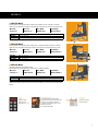
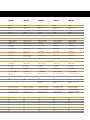
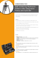
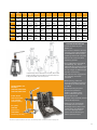
1
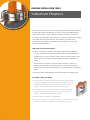
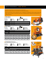
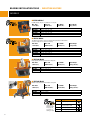
Maintenance Tools
1
SAFETY
WARNING Failure to observe the following warnings could create a risk of serious injury.
Never spin a bearing with compressed air. The rollers may be forcefully expelled.
Proper maintenance and handling procedures are critical. Always follow installation instructions and maintain proper lubrication.
Tensile stresses can be very high in tightly fitted bearing components. Attempting to remove such components by cutting the cone
(inner race) may result in a sudden shattering of the component causing fragments of metal to be forcefully expelled. Always use
properly guarded presses of bearing pullers to remove bearings from shafts, and always use suitable personal protective equipment,
including safety glasses.
Disclaimer
Every reasonable effort has been made to ensure the accuracy of the information contained in this writing,
but no liability is accepted for errors, omissions or for any other reason.
Less Friction.
More Solutions.
With more than 100 years of experience in bearing
technology, Timken understands the importance of
proper maintenance procedures in maximizing product
and equipment life. High-quality Timken maintenance
products help to decrease downtime and operating costs.
Our line of maintenance tools are an example of how
we extend beyond bearings with friction management
solutions to keep your business running smoothly. These
value-added products are grounded in our knowledge
of motion, lubrication, friction and metallurgy. They
are designed to help you extend bearing life in your
applications through proper installation, removal and
service.
For more than 100 years, Timken has provided quality
products to the industrial marketplace. Our maintenance
tools are made to the same standards you’ve come to
expect from Timken® bearings. Our field support team is
available to help you use these tools appropriately, as well
as identify other Timken solutions that may boost your
productivity and save you money.
Through our products, programs and services, we’re
providing less friction and more solutions to help you
achieve greater success.
For more information, contact your local Timken
distributor or sales representative.
Bearing INSTALLATION Tools
Induction Heaters
Timken offers a large assortment of high-quality induction heaters designed
for demanding industrial applications. They can heat and radially expand a
wide variety of gears, rings, couplings, bearings and other components.
All heaters are produced in accordance with International (IEC) and European
(CE) health and safety requirements. They feature a microprocessorcontrolled power supply, automated time and temperature control and
automatic demagnetization.
Why choose an induction heater?
nInduction
heating is a superior, fast and controlled heating method. It
is a safe and environmentally friendly alternative for traditional heating
methods such as ovens, oil baths or blow torches. These methods cause
smoke, fumes or oil waste and are hazardous for personal health and
safety.
nTimken
induction heaters use the principle of induction, similar to a
transformer. The heater and yokes remain cool; only the work piece is
heated. During the induction heating cycle, a certain degree of magnetism
occurs.
nAll Timken
heaters demagnetize automatically after each heating cycle.
Versatility, safety and quality
nTimken
induction heaters can be used for heating gear wheels,
bushings, couplings and other components. Proper mounting
lengthens the life span of your equipment, and controlled
induction heating helps prevent unnecessary damage.
nDigital
electronics provide optimal control during the heating
process and automatically select the most efficient power
supply to ensure balanced and fast heating.
nTimken
nThe
induction heaters are dependable.
robust and easy-to-use designs offer you reliable heaters that are
suitable for continuous operation in industrial environments.
4
New heater Models - turbo design
• Powerful turbo design for demanding industrial applications
• Maximum capacity for both work piece sizes and heating capability
• Plug & Heat design models are delivered with a molded plug* (available for 120V and 230V models only)
•S
afe: all Timken heaters automatically select the most effective power setting to ensure optimal and
balanced heating
n VHIN 33 Model
Plug & Heat Turbo Model
Min. Bore
Max. O.D.
Max. Width
Max. Weight
10 mm (0.4”)
350 mm (13.8”)
135 mm (5.3”)
40 kg (88.2 lb)
VHIN 331
VHIN 331GB
VHIN 331EN
VHIN 332GB
VHIN 332US
230V - ºC, Yokes 10, 14, 40
230V - ºC, Yokes 10, 14, 40
230V - ºC, Yokes 10, 14, 40
120V - ºC, Yokes 10, 14, 40
120V - ºF, Yokes 10, 14, 40
n VHIS 75 Model
Plug & Heat Turbo Swing Arm Model
Min. Bore
Max. O.D.
Max. Width
Max. Weight
15 mm (0.6”)
750 mm (29.5”)
230 mm (9.1”)
95 kg (209.4 lb)
VHIS 751
VHIS 751GB
VHIS 751EN
VHIS 752GB
VHIS 754US
230V - ºC, Yokes 14, 30, 60
230V - ºC, Yokes 14, 30, 60
230V - ºC, Yokes 14, 30, 60
120V - ºC, Yokes 14, 30, 60
120V - ºF, Yokes 14, 30, 60
HEATING EXAMPLES: 20-110°C (68-230°F)
Voltage Work Piece
110V
110V
230V
230V
6314
23148
23148
23156
Weight
kg
2.6
63.0
63.0
95.0
Weight
lbs.
5.7
138.9
138.9
209.4
O.D.
mm
150
400
400
460
O.D.
inch
5.9”
15.7”
15.7”
18.1”
Bore
mm
70
240
240
280
Bore
inch
2.8”
9.4”
9.4”
11.0”
Heating
Time
1.5 min.
53.0 min.
53.0 min.
45.0 min.
n VHIS 400 Model Turbo Design
Sliding support
for heating
in horizontal
position.
Mobile extra-powerful heater with unique swing arm
Min. Bore
Max. O.D.
Max. Width
Max. Weight
60 mm (2.4”)
920 mm (36.2”)
350 mm (13.8”)
550 kg (1,212 lbs.)
VHIS 4001
VHIS 4002
VHIS 4003US
400V - ºC, Yoke 80
450V - ºC, Yoke 80
500V - ºF, Yoke 80
HEATING EXAMPLES: 20-110°C (68-230°F)
Work Piece
Weight
kg
Weight
lbs.
O.D.
mm
O.D.
inch
Bore
mm
Bore
inch
Heating
Time
Bearing 23156
Gear wheel
95.8
300
211
661
460
600
18.1
23.6
11.0
210
280
8.3
4 min.
3 min.
5
Bearing INSTALLATION Tools
•
Induction Heaters
Models
n VHIN 10 Model
Portable design, easy to use, ideal for on-site jobs.
Min. Bore
15 mm (0.6”)
VHIN 10
VHIN 10GB
VHIN 10US
VHIN 10EN
VHIN 101GB
Max. O.D.
210 mm (8.3”)
Max. Width
120 mm (4.8”)
Max. Weight
15 kg (33 lbs.)
230V - ºC, Yokes 10, 14, 40
230V - ºC, Yokes 10, 14, 40
120V - ºF, Yokes 10, 14, 40
230V - ºC, Yokes 10, 14, 40
120V - ºC, Yokes 10, 14, 40
n VHIS 35 Model
This bench-top model is the most popular among customers and features
a unique swing arm for ergonomic working.
Min. Bore
Max. O.D.
Max. Width
Max. Weight
15 mm (0.6”)
480 mm (18.9”)
150 mm (5.9”)
35 kg (77 lbs.)
VHIS 35
VHIS 35GB
VHIS 35EN
VHIS 351GB
VHIS 351US
230V - ºC, Yokes 14, 30, 60
230V - ºC, Yokes 14, 30, 60
230V - ºC, Yokes 14, 30, 60
120V - ºC, Yokes 14, 30, 60
120V - ºF, Yokes 14, 30, 60
n VHIS 100 Model
Large capacity bench-top model with swing arm.
Min. Bore
Max. O.D.
Max. Width
Max. Weight
30 mm (1.2”)
720 mm (28.3”)
200 mm (7.9”)
125 kg (275 lbs.)
VHIS 1003
VHIS 1005
VHIS 1011US
450V - ºC, Yokes 20, 70
400V - ºC, Yokes 20, 70
500V - ºF, Yokes 20, 70
n VHIS 200 Model
Mobile heavy-duty heater with unique swing arm
Min. Bore
Max. O.D.
Max. Width
Max. Weight
30 mm (1.2”)
1020 mm (40.2”)
265 mm (10.4”)
250 kg (551 lbs.)
VHIS 2002
VHIS 2003
VHIS 2007US
400V - ºC, Yoke 80
450V - ºC, Yoke 80
500V - ºF, Yoke 80
please add the
following suffix to
the appropriate
part number to
identify your plug:
6
Suffix
-
Plug type
European plug 230V
GB
US
UK 2-pin plug for 120V
UK-3 pin plug for 230V
US 2-flat pin plug 120 V
EN
3-round pin plug 230 V
Models
n VHIN 550 Model
Powerful heater for exceptionally heavy components up to 600 kg (1,322 lbs.). Popular in workshops
within steel mills, paper mills and gear box manufacturing. Heats parts in horizontal and vertical positions.
Min. Bore
Max. O.D.
Max. Width
Max. Weight
85 mm (3.4”)
900 mm (35.4”)
400 mm (15.8”)
600 kg (1,322 lbs.)
VHIN 5502
VHIN 5503
VHIN 5504US
400V - ºC, Yoke 100
450V - ºC, Yoke 100
500V - ºF, Yoke 100
n VHIN 800 Model
Powerful heater for exceptionally heavy components up to 1,250 kg (2,756 lbs.). Popular in workshops
within steel, rail, wind, paper and gear box operations. Heats parts in horizontal and vertical positions.
Min. Bore
Max. O.D.
Max. Width
Max. Weight
85 mm (3.4”)
1400 mm (55.1”)
420 mm (16.5”)
1250 kg (2,756 lbs.)
VHIN 8002
VHIN 8003
VHIN 8004US
400V - ºC, Yoke 150
450V - ºC, Yoke 150
500V - ºF, Yoke 150
n VHIN 850 Model
The biggest standard size and capacity design.
Powerful heater for exceptionally heavy components up to 1,500 kg (3,300 lbs.).
Min. Bore
Max. O.D.
Max. Width
Max. Weight
145 mm (5.7”)
1760mm (69,29”)
700 mm (27.6”)
1500 kg (3,300 lbs.)
VHIN 8501
VHIN 8502
VHIN 8503US
400V - ºC, Yoke 150
450V - ºC, Yoke 150
500V - ºF, Yoke 150
Contact your local Timken representative for assistance in building a custom solution for extremely large
heaters.
DIGITAL
CONTROLS:
All digital controls
operate by time or
temperature in °C or °F
Temperature probe:
Each Timken Induction Heater model is
supplied with a magnetic temperature probe.
A clamp is also available for nonferrous
components. Replacement probes are also
available for purchase.
Part number: VHIA 100001
HORIZONTAL
SUPPORT:
Support for heating in
horizontal position.
7
Bearing INSTALLATION Tools
•
Induction Heaters
Models
Type
VHIN 10
VHIN 33
VHIS 35
VHIS 75
VHIS 100
3.6 k VA
120V/20A
230V/16A
—
50/60 Hz
No
Yes
3.6 k VA
120V/15A
230V/16A
—
50/60 Hz
No
Yes
3.6 kVA
120/20A
230V/16A
—
50/60Hz
Yes
Yes
3.6 kVA
120V/15A
230V/16A
—
50/60Hz
Yes
Yes
8 kVA
400/450/500V
20A
230V
50/60Hz
Yes
—
15 kg (33.1 lbs.)
10 kg (22.1 lbs.)
15 mm (0.6”)
210 mm (8.3”)
40 kg (88,2 lbs.)
25 kg (55,1 lbs.)
10 mm (0.4”)
350 mm (13.8”)
120 mm (4.7”)
135 mm (5.3”)
35 kg (77.2 lbs.)
20 kg (44.1 lbs.)
15 mm (0.6”)
340/480 mm
(13.4”/18.9”)
150 mm (5.9”)
95 kg (209.4 lbs.)
50 kg (110.2 lbs.)
15 mm (0.6”)
520/750 mm
(20.5”/29.5”)
230 mm (9.1”)
125 kg (275.6 lbs.)
75 kg (165.4 lbs.)
30 mm (1.2”)
480/720 mm
(18.9”/28.4”)
200 mm (7.9”)
120 x 130 mm
(4.7” x 5.1”)
40 mm (1.6”)
135 x 135 mm
(5.3” x 5.3”)
95/40 mm (3.7”/1.6”)
150 x 140 mm
(5.9” x 5.5”)
60 mm (2.4”)
200 x 230 mm
(7.9” x 9.1”)
120/60 mm (2.4”/4.7”)
200 x 180 mm
(7.9” x 7.1”)
70 mm (2.8”)
Pole Height
ControlS
Temperature Control
Max. Temp
Time Control
Max. Time
Auto Power Reduction
options
Standard / Optional Yokes
130 mm (5.1”)
135 mm (5.3”)
140 mm (5.5”)
230 mm (9.1”)
210 mm (8.3”)
150° C (302° F)
240° C (464° F)
240° C (464° F)
240° C (464° F)
240° C (464° F)
0 – 30 Min.
—
0 – 45 Min.
Automatically
0 – 45 Min.
—
0 – 45 Min.
Automatically
0 – 60 Min.
Automatically
10,14, 20, 40 mm
(0.4”, 0.6”, 0.8”, 1.6”)
(in case)
—
—
—
—
—
10, 14, 20, 30, 40, 50,
60 mm (0.4”, 0.6”, 0.8”,
1.2”, 1.6”, 2.0”, 2.4”)
(in carry box)
Yes
—
—
10, 14, 20, 30, 40, 50,
60 mm (0.4”, 0.6”, 0.8”,
1.2”, 1.6”, 2.0”, 2.4”)
(in carrier)
Yes
—
—
20, 30, 40, 50, 70 mm
(0.8”, 1.2”, 1.6”, 2.0”, 2.8”)
Support for Horizontal
Heating
Mobile
Temperature Control
7, 10, 14, 20, 40 mm
(0.3”, 0.4”, 0.6”, 0.8”,
1.6”)
Yes
435 x 225 x 275 mm
(17.1” x 8.9” x 10.8”)
500 x 250 x 350 mm
(19.7” x 9.8” x 13.8”)
21 kg (46.3 lbs.)
(includes yokes)
600 x 220 x 275 mm
(23.6” x 8.7” x 10.8”)
650 x 290 x 350 mm
(25.6” x 11.4” x 13.8”)
23 kg (50.7 lbs.)
340 x 290 x 380 mm
(13.4” x 11.4” x 15.0”)
600 x 450 x 600 mm
(23.6” x 17.7” x 23.6”)
31 kg (68.3 lbs.)
440 x 370 x 360 mm
(17.3” x 14.6” x 14.2”)
700 x 500 x 700 mm
(27.6” x 19.7” x 27.6”)
38 kg (83.8 lbs.)
630 x 365 x 470 mm
(24.8” x 14.4” x 18.5”)
700 x 500 x 700 mm
(27.6” x 19.7” x 27.6”)
53 kg (116.8 lbs.)
yes
yes
yes
yes
yes
yes
yes
yes
yes
yes
yes
yes
yes
yes
yes
yes
yes
yes
yes
yes
yes
yes
yes
yes
yes
yes
yes
yes
yes
yes
yes
yes
yes
yes
yes
yes
yes
yes
yes
yes
Electricity
Power Rating
Voltage/Current
Different Voltage Option
Frequency
Swing Arm
Plug
Work Piece
Max. Weight
- Bearings
- Other Parts
Min. Bore Diameter
Max O.D.
Vertical/Horizontal
Max. Work Piece Width
POLE DIMENSIONS
Operating area
Width x Height
Pole Section
DIMENSIONS
Dimensions
Package Size
Mass Heater Body
(excludes yokes)
MISCELLANEOUS
Sound Signal
Temperature Hold
Demagnetizing <2 A/cm
Thermal Safety Guard
Magnetic Temperature Probe
DIGITAL DISPLAY
Temperature
Time
Error Report
8
Yes
—
—
VHIS 200
VHIS 400
VHIN 550
VHIN 800
VHIN 850
12 kVA
400/450/500V
32A
—
50/60Hz
Yes
—
12 kVA
400/450/500V
32A
—
50/60Hz
Yes
—
24 kVA
400/450/500V
63A
—
50/60Hz
No
—
40 kVA
400/450/500V
100A
50/60Hz
No
-
40 kVA
400/450/500V
100A
50/60Hz
No
-
250 kg (551.2 lbs.)
150 kg (330.7 lbs.)
30 mm (1.2”)
700/1020 mm
(27.6”/40.2”)
265 mm (10.4”)
550 kg (1,212.5 lbs.)
450 kg (992.1 lbs.)
60 mm (2.4”)
920 mm (36.2”)
600 kg (1,322.8 lbs.)
350 kg (771.6 lbs.)
85 mm (3.4”)
900 mm (35.4”)
1250 kg (2,755.8 lbs.)
750 kg (1,653.5 lbs.)
85 mm (3.4”)
1400 mm (55.1”)
1500 kg (3,300 lbs.)
800 kg (1,764 lbs.)
145 mm (5.7”)
1760 mm (69,29”)
350 mm (13.8”)
400 mm (15.8”)
420 mm (16.5”)
700 mm (27.6”)
265 x 310 mm
(10.4” x 12.2”)
80 mm (3.2”)
390 x 400 mm
(15.4” x 15.8”)
100 mm (3.9”)
660 x 420 mm
( 26.0” x 16.5”)
150 mm (5.9”)
750x700 mm
(29,52”x27,56”)
240 mm (9.5”)
310 mm (12.2”)
350 x 305 mm
(13.8” x 12.0”)
170/110 x 80 mm
(6.7”/4.3” x 3.2”)
305 mm (12.0”)
390 mm (15.4”)
660 mm (26.0”)
750 mm (29.5”)
240° C (464° F)
240° C (464° F)
240° C (464° F)
240° C (464° F)
240° C (464° F)
0 – 99 Min.
Automatically
0 – 99 Min.
Automatically
0 – 99 Min.
Automatically
0 – 99 Min.
Automatically
0 – 99 Min.
Automatically
20, 30, 40, 60, 80 mm
(0.8”, 1.2”, 1.6”,
2.4”, 3.2”)
40, 60, 80 mm
(1.6”, 2.4”, 3.2”)
60, 80, 100 mm
(2.4”, 3.2”, 4.0”)
60, 80, 100, 150 mm
(2.4”, 3.2”, 4.0”, 5.9”)
60, 80, 100, 150 mm
(2.4”, 3.2”, 4.0”, 5.9”)
Yes
Yes
—
Yes
Yes
—
Yes
Yes
Yes
On request up to 480°C
( 896°F)
On request up to 480°C
(896°F)
On request up to 480°C
(896°F)
950 x 640 x 1000 mm
(37.4” x 25.2” x 39.4”)
1140 x 750 x 1000 mm
(44.9” x 29.5” x 39.4”)
120 kg (264.6 lbs.)
1200 x 640 x 1000 mm
(47.2” x 25.2” x 39.4”)
1250 x 750 x 1000 mm
(49.2” x 29.5” x 39.4”)
205 kg (452.0 lbs.)
1000 x 500 x 1350 mm
(39.4” x 19.7” x 53.2”)
1400 x 700 x 1600 mm
(55.1” x 27.6” x 63.0”)
200 kg (440.9 lbs.)
1500 x 600 x 1470 mm
(59.1” x 23.6” x 57.9”)
1920 x 950 x 1720 mm
(75.6” x 37.4” x 67.7”)
660 kg (1,455.1 lbs.)
2300 x 1000 x 1000 mm
(90.6” x 39.4” x 39.4”)
2750 x 1350 x 1350 mm
(108” x 53” x 53”)3000 kg
(6614,0 lbs.)
yes
yes
yes
yes
yes
yes
yes
yes
yes
yes
yes
yes
yes
yes
yes
yes
yes
yes
yes
yes
yes
yes
yes
yes
yes
yes
yes
yes
yes
yes
yes
yes
yes
yes
yes
yes
yes
yes
yes
yes
9
Bearing REMOVAL Tools
Self-centering Hydraulic
Pullers with Integrated
Pump and Cylinder
The new Timken Self-centering Hydraulic Pullers are practical and convert
easily to either a 2- or 3-arm puller. The arms slide inwards or outwards
simultaneously.
Features:
n Integrated
n Compact
n Sets
pump, cylinder, hose and puller with safety-release valve.
design: The self-contained hydraulic pump and puller saves space.
are supplied in handy carrying case.
nMulti-purpose:
Ideal for pulling a wide variety of press-fit parts including
bearings, wheels, bushings, gears and pulleys.
nThe
pump handle is able to rotate 360-degrees providing flexibility to use
the puller in the most convenient position.
n Pullers
can be used with two or three legs.
n Available
with accessories.
Benefits
Practical:
• Ergonomic design - easy to handle
• Flexible - use in any position with a pump handle that rotates 360 degrees
• Protective - prevents damage to shafts and objects being pulled
• Efficient - saves time
• Accessories - available for models from 4 to 12 tons
Safe:
The safety-release valve prevents overloading and ensures that you never
exceed maximum force.
Easy-to-use:
The VHPS20 and VHPS30 ton models are equipped with an innovative 2-stage
pump for easier and safer pumping.
Rugged:
The greater the pulling force, the tighter the jaws grip the object concerned.
The arms cannot be bent or deflected.
Economical:
The combination 2- or 3- arm puller gives you 2 pullers for the price of one.
10
MODEL
Max.
Withrawal Arm length
Force
Width of
Grip
STROKE
A
B
C
190 mm
(7,48“)
230 mm
(9,1“)
280 mm
(11“)
305 mm
(12“)
365 mm
(14,4“)
465 mm
(18,3“)
325 mm
(12,8“)
380 mm
(15“)
450 mm
(17,7“)
485 mm
(19,1“)
570 mm
(22,4“)
680 mm
(26,8“)
60 mm
(2,4“)
70 mm
(3,4“)
85 mm
(3,4“)
85 mm
(3,4“)
111 mm
(4,4“)
111 mm
(4,4“)
13 mm
(0,5“)
13 mm
(0,5“)
13 mm
(0,5“)
15 mm
(0,6“)
20 mm
(0,8“)
20 mm
(0,8“)
10 mm
(0,4“)
10 mm
(0,4“)
13 mm
(0,5“)
17 mm
(0,7“)
27 mm
(1,1“)
27 mm
(1,1“)
22 mm
(0,9“)
22 mm
(0,9“)
27,5 mm
(1,1“)
29 mm
(1,1“)
33 mm
(1,3“)
38 mm
(1,5“)
VHPS4
4t
VHPS6A
6t
VHPS8
8t
VHPS12
12 t
VHPS20
20 t
VHPS30
30 t
D
-
E
F
G
MASS
40 mm
(1,6“)
50 mm
(2“)
70 mm
(2,7“)
70 mm
(2,7“)
62 mm
(2,4“)
85 mm
(3,3“)
42 mm
(1,7“)
45 mm
(1,8“)
50 mm
(2“)
60 mm
(2,4“)
80 mm
(3,2“)
98 mm
(3,9“)
22 mm
(0,9“)
23 mm
(0,9“)
25 mm
(1“)
28 mm
(1,1“)
40 mm
(1,6“)
50 mm
(2“)
8 kg
(18lbs.)
10 kg
(22lbs.)
12 kg
(26lbs.)
15 kg
(33lbs.)
25 kg
(55lbs.)
36 kg
(80lbs.)
PULLER HANDLING TIPS
• Check condition of puller
before use.
• If there are indications of wear
and tear such as ground-down,
overloaded or worn-out parts,
exchange them with new parts.
• Do not use a hammer when
operating spindle.
• If any indications of overload,
stiff working, etc., can be
observed during pulling, please
stop the procedure at once. Try
to use a larger or different type
of puller if necessary.
1 = Max. Aslengte / Reach / Abziehtiefe / Portée max. / Alcance máx.
2 = Max. Spreiding / Spread / Spreizweite / Ecartement / Dispersión
3 = Slag / Stroke / Hub / Course vérin / Carrera
ACCESSORIES SET
MODELS:
VHPT490, VHPT690A,
VHPT890, VHPT1290
Puller shown
with accessories.
(set supplied
without pump)
For puller
VHPS6A
please use
VHPT690A
accessory set only
• For proper puller engagement,
the jaws/legs should be
centered.
• When pulling, make sure
puller and pulled part are kept
covered by the safety blanket
provided.
• When operating the puller
please wear protective
clothing, including safety
shoes, protective glasses,
gloves and helmet.
• Spindle and puller body should
always be kept clean.
•M
ake sure you avoid puller
overload, as it can result in
breakage of the puller’s arms
and/or beam. This breakage
can cause damage to the
puller, shaft and bearing as
well as personal injury.
Technical specifications for the accessory sets can be found on page 13
11
Bearing REMOVAL Tools
Hydraulic Pullers
Timken has a wide range of self-contained portable hydraulic pulling
systems that have capacities from four to 30 tons.
They are excellent for the removal of all kinds of shaft-fitted parts.
Advantages:
n Integrated
n Compact
n Sets
pump, cylinder, hose and puller with safety-release valve.
design: The self-contained hydraulic pump and puller saves space.
are supplied in handy carrying case.
n Multi-purpose:
Ideal for pulling a wide variety of press-fit parts including
bearings, wheels, bushings, gears and pulleys.
n The
pump handle is able to rotate 360-degrees providing flexibility to use
the puller in the most convenient position.
n Pullers
can be used with two or three legs.
n Available
with accessories.
Hydraulic Pullers HANDLING TIPS
• Check condition of puller before use.
• If there are indications of wear and tear such as ground-down,
overloaded or worn-out parts, exchange them with new parts.
• Do not use a hammer when operating spindle.
• If any indications of overload, stiff working, etc., can be observed
during pulling, please stop the procedure at once. Try to use a larger or
different type of puller if necessary.
• For proper puller engagement, the jaws/legs should be centered.
• When pulling, make sure puller and pulled part are kept covered by the
safety blanket provided.
• When operating the puller please wear protective clothing, including
safety shoes, protective glasses, gloves and helmet.
• Spindle and puller body should always be kept clean.
12
MODEL
Max.
Withrawal Arm length
Force
Width of
Grip
STROKE
A
B
C
D
E
F
G
MASS
185 mm
(7.3”)
230 mm
(9,1“)
230 mm
(9.1”)
270 mm
(10.6”)
360 mm
(14.2”)
360 mm
(14.2”)
275 mm
(10.8”)
300 mm
(11.8”)
350 mm
(13.8”)
375 mm
(14.8”)
520 mm
(20.5”)
550 mm
(21.7”)
60 mm
(2,4“)
85 mm
(3.4”)
85 mm
(3,4“)
85 mm
(3,4“)
111 mm
(4,4“)
111 mm
(4,4“)
11 mm
(0.4”)
11 mm
(0.4”)
11 mm
(0.4”)
14 mm
(0.6”)
20 mm
(0,8“)
20 mm
(0,8“)
6 mm
(0.2”)
10 mm
(0,4“)
10 mm
(0,4“)
10 mm
(0,4“)
27 mm
(1,1“)
27 mm
(1,1“)
22 mm
(0,9“)
25 mm
(1.0”)
25 mm
(1.0”)
29 mm
(1,1“)
33 mm
(1,3“)
38 mm
(1,5“)
32 mm
(1.3”)
51 mm
(2.0”)
51 mm
(2.0”)
51 mm
(2.0”)
60 mm
(2.4”)
60 mm
(2.4”)
84 mm
(3.3”)
122 mm
(4.8”)
122 mm
(4.8”)
118 mm
(4.6”)
161 mm
(6.3”)
155 mm
(6.1”)
42 mm
(1,7“)
50 mm
(2.0”)
50 mm
(2.0”)
60 mm
(2,4“)
80 mm
(3,2“)
98 mm
(3,9“)
22 mm
(0,9“)
25 mm
(1.0”)
25 mm
(1.0”)
28 mm
(1,1“)
40 mm
(1,6“)
50 mm
(2“)
4.5 kg
(9.9 lbs.)
6.5 kg
(14.3 lbs.)
6.5 kg
(14.3 lbs.)
8 kg
(17.6 lbs.)
22 kg
(48.5 lbs.)
32 kg
(70.6 lbs.)
VHPT4
4t
VHPT6A
6t
VHPT8
8t
VHPT12
12 t
VHPT20
20 t
VHPT30
30 t
AccessorY Sets (hydraulic pump Not included)
MODEL
VHPT490
VHPT690A
VHPT890
VHPT1290
Arm length
Width of
Grip
Min. OD
Max. OD
MASS
250 mm
(9.8”)
280 mm
VHPT6A
(11.0”)
280 mm
VHPT8
(11.0”)
325 mm
VHPT12
(12.8”)
110 mm
(4.3”)
220 mm
(8.7”)
210 mm
(8.3”)
290 mm
(11.4”)
25 mm
(1.0”)
50 mm
(2.0”)
50 mm
(2.0”)
80 mm
(3.2”)
110 mm
(4.3”)
150 mm
(5.9”)
150 mm
(5.9”)
225 mm
(8.9”)
8.5 kg
(18.7 lbs.)
12.5 kg
(21.6 lbs.)
12.5 kg
(21.6 lbs.)
18 kg
(39.7 lbs.)
Puller
VHPT4
SPLITTER ACCESSORY SET
MODELS:
VHPT490, VHPT690A,
VHPT890, VHPT1290
1- Arm Length
2- Width of Grip
3- Stroke
Puller shown with splitter accessory.
(set supplied without pump)
13
Bearing installation Tools
Impact Fitting Tool
Proper mounting allows the load to be transmitted to the ring
experiencing the interference fit. This way, mounting forces are not
transmitted via the rolling elements, avoiding damage to the raceways.
This Metric mounting
set consists of:
n33
n3
Collets
Sleeves
n1
Impact hammer
weight : 0.7 kg (1.5 lbs.)
absorbs shock and vibration
nCase
dimensions:
430 x 320 x 100 mm
(16.9” x 12.6” x 4.0”)
Impact Fitting Tool HANDLING TIPS
• When operating the impact fitting tool, please wear protective clothing,
including safety shoes, protective glasses, gloves and helmet.
• Do not use the collets to mount components that have a temperature
greater than 80° C (176° F).
• Never mount the cup and cone of a tapered bearing together or mount
a cone from the front face.
• Proper mounting is essential to ensure long bearing life. Designed to
permit the safe, precise and quick mounting of bearings, bushings,
sealing rings, cam wheels and pulleys, the Timken Impact Fitting Tool
Set features impact-resistant plastic collets, which help to avoid metalto-metal contact and the resulting shaft damage.
• During the mounting of bearings, such as ball and spherical roller
bearings, where the faces lie in the same plane, the collets enable the
load to be transmitted to the ring experiencing the interference fit. In
this way, mounting forces are not transmitted via the rolling elements
and hence damage to the raceways is avoided.
Part Number: VIFT 3300
14
Sleeve
Ring
All ISO bearings codes ending with:
60,62,
63,64
12,22,
13,23
A1
10-26
10-30
000
200
6000
6200
10-35
12-28
12-32
300
001
201
6300
6001
6201
129
1200
2200
1300
12-37
301
6301
15-32
15-35
002
202
6002
6202
15-42
302
6302
17-35
003
17-40
203
6003
16003
6203
17-47
303
6303
20-42
20-47
004
204
6004
6204
20-52
304
403
005
205
6304
6403
6005
6205
305
404
006
206
6305
6404
6006
6206
306
405
007
207
6306
6405
6007
6207
307
406
008
208
6307
6406
6006
6208
308
407
009
209
6308
6407
6009
6209
309
408
010
210
6309
6408
6010
6210
310
409
6310
6409
B2
25-47
25-52
25-62
30-55
30-62
30-72
C3
35-62
35-72
35-80
40-68
40-80
40-90
45-75
45-85
45-100
50-80
50-90
50-110
1201
2201
1301
2301
70, 72B, 73B
7000
222,213,223
NU,NJ,N
234
302, 322,
303, 330
3200
3201
7301
7202B
1203
2203
1303
2303
3202
3302
30302
7203B
3203
30203
7303B
3303
30303
7004
7204B
3204
7304B
3304
7005
7205B
204
30204
21304
304
30304
3205
22205
205
7305B
3305
21305
305
30205
32205
30305
7206B
3206
22206
206
7306B
3306
21306
7007
7207B
306
405
3207
22207
207
7307B
3307
21307
307
406
1208
7208B
3208
22208
208
1308
2308
7308B
3308
21308
22308
308
407
1209
2209
1309
2309
7209B
3209
22209
209
7309B
3309
21309
22309
309
408
1210
2210
7210B
3210
22210
210
1310
2310
7310B
3310
21310
22310
310
409
1205
2205
1305
2305
1206
2206
1306
2206
1207
2207
1307
2307
320, 313,
323, 332
7300
1202
2202
1302
2302
1204
2204
1304
2304
32, 33
30206
32206
30306
30207
32207
30307
30208
32208
30308
32009
30209
32209
30309
32303
32004
32304
32005
33205
31305
32305
32006
33206
31306
32306
32007
33207
31307
32307
32008
33208
31308
32308
33209
31309
32309
32010
33210
33010
30210
32210
JM205149/JM205110
30310
31310
32310
Impact rings 50-90, 45-100, 50-110 also fit the following bearing where only the outer ring is to be fitted (e.g. shaft is not installed)
C3
50-90
6011
6012
45-100
6013
1211
7211B
3211
22211
211
6211
2211
7212B
50-110
6014
1212
7213B
3212
22212
212
6015
1213
3213
22213
213
6212
2213
3211
21311
311
6213
2213
22311
410
6311
1311
6410
2311
For tapered bearings, impact rings fit outer ring and also inner ring if driving is from larger diameter side.
The numbers on each impact ring (e.g. 25-62) are clearly marked on the ring. The first figure refers to shaft diameter, the second to bearing outer diameter
15
WARNING:
Proper maintenance and handling practices are critical. Failure to follow user manual instructions can result in equipment
failure, creating a risk of serious bodily harm.
Bearings • Steel •
Precision Components • Lubrication
Seals • Remanufacture and Repair •
Industrial Services
www.timken.com
Timken® is a registered trademark of
The Timken Company
© 2009 The Timken Company
Printed in Europe
Order No. E7710-GB
•