1
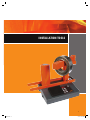
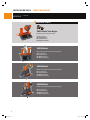
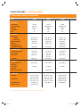
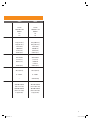
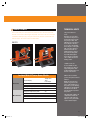
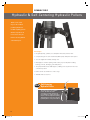
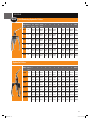
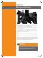
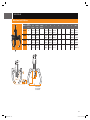
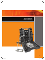
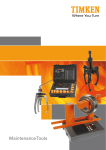
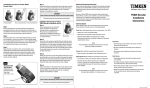
Maintenance Tools
269612.indd 1
7/7/07 3:08:55 AM
Less Friction.
More Solutions.
With more than 100 years of experience in bearing
technology, Timken understands the importance of
proper maintenance procedures in maximizing product
and equipment life. High-quality Timken maintenance
products help to decrease downtime and operating costs.
Our line of maintenance tools are an example of how
we extend beyond bearings with friction management
solutions to keep your business running smoothly. These
value-added products are grounded in our knowledge
of motion, lubrication, friction and metallurgy. They
are designed to help you extend bearing life in your
applications through proper installation, removal and
service.
For more than 100 years, Timken has provided quality
products to the industrial marketplace. Our field
support team is available to help you use these tools
appropriately, as well as identify other Timken solutions
that may boost your productivity and save you money.
Through our products, programs and services, we’re
providing less friction and more solutions to help you
achieve greater success.
For more information, contact your local Timken
distributor or sales representative.
269612.indd 2
7/7/07 3:09:29 AM
Installation Tools
INDUCTION HEATERS ..................................................................................... 4
IMPACT FITTING TOOLS ..............................................................................14
Removal Tools
HYDRAULIC & SELF-CENTERING HYDRAULIC PULLERS .....18
MECHANICAL PULLERS ..............................................................................20
Accessories .............................................................................................23
1
269612.indd 3
7/7/07 3:10:02 AM
WARNING:
Proper maintenance and handling practices are critical. Failure to follow user
manual can result in equipment failure, creating a risk of serious bodily harm.
DO NOT WEAR
METAL OBJECTS
OR WATCHES.
USE HEAT
PROTECTIVE
GLOVES.
PROHIBITED FOR
PEOPLE WITH
A PACEMAKER
AND/OR HEARING
AID.
CAUTION
READ THE
INSTRUCTIONS.
269612.indd 4
DO NOT OPERATE AN
INDUCTION HEATER IN
AREAS WHERE THERE IS A
RISK OF AN EXPLOSION.
7/7/07 3:10:24 AM
INSTALLATION TOOLS
3
269612.indd 5
7/7/07 3:10:34 AM
INSTALLATION TOOLS
Induction Heaters
Timken offers a large
assortment of high-quality
induction heaters designed
for demanding industrial
applications. They can
heat and radially expand
a wide variety of gears,
rings, couplings, bearings
and other components.
All heaters are produced
in accordance with
International (IEC) and
European (CE) health and
safety requirements. They
feature a microprocessor
controlled power supply,
automated time and
temperature control and
automatic demagnetization.
Why choose an induction heater?
Induction heating is a superior, fast and controlled heating method. It is a safer
and more environmentally friendly alternative to traditional heating methods
such as ovens, oil baths or blow torches. These methods cause fumes or oil
waste and are not recommended for personal health and safety.
Timken induction heaters use the principle of induction, similar to a transformer.
The heater and yokes remain cool; only the work piece is heated. During the
induction heating cycle, a certain degree of magnetism occurs. All Timken
heaters demagnetize automatically after each heating cycle.
Induction heaters with this
icon next to them means
that it comes with a plug
and is ready to use.
Versatility, safety and quality.
Timken induction heaters can be used
for heating gear wheels, bushings,
couplings and other components.
Proper mounting may lengthen the
life span of your equipment, and
controlled induction heating helps to
prevent unnecessary damage.
Digital electronics provide optimum
control during the heating process
and automatically select the most
efficient power supply to help ensure
balanced and fast heating.
4
269612.indd 6
7/7/07 3:10:44 AM
MODELS
VHIN10 Model
Portable design, easy to use, ideal for on-site jobs. Includes four yokes.
Min. Bore 15 mm (0.6”)
Max. O.D. 210 mm (8.3”)
Max. Width 120 mm (4.8”)
Max. Weight 15 kg (33 lbs.)
VHIN33 Model
Powerful turbo design. Automatically selects the most effective power
setting to ensure optimal and balanced heating.
FPO
Min. Bore 10 mm (0.4”)
Max. O.D. 350 mm (13.8”)
Max. Width 135 mm (5.3”)
Max. Weight 40 kg (88.2 lbs.)
* Not available in the U.S. or Canada
VHIN35 Model
Basic model with choice of four yokes. Picture at left shows optional
vertical support arm.
Min. Bore 15 mm (0.6”)
Max. O.D. 480 mm (18.9”)
Max. Width 150 mm (5.9”)
Max. Weight 35 kg (77 lbs.)
VHIS35 Model
This bench-top model features a unique swing arm for ergonomic
working.
Min. Bore 15 mm (0.6”)
Max. O.D. 480 mm (18.9”)
Max. Width 150 mm (5.9”)
Max. Weight 35 kg (77 lbs.)
5
269612.indd 7
7/7/07 3:10:57 AM
INSTALLATION TOOLS
MODELS
•
INDUCTION HEATERS
– CONTINUED
#
1
POPULAR CHOICE
VHIS75 Model Turbo Design
Plug & Heat turbo swing arm model.
Min. Bore 15 mm (0.6”)
Max. O.D. 750 mm (29.5”)
Max. Width 230 mm (9.1”)
Max. Weight 95 kg (209.4 lb)
VHIS100 Model
Large capacity bench-top model with swing arm.
Min. Bore 30 mm (1.2”)
Max. O.D. 720 mm (28.3”)
Max. Width 200 mm (7.9”)
Max. Weight 125 kg (275 lbs.)
VHIS200 Model
Mobile heavy-duty heater with unique swing arm.
Min. Bore 30 mm (1.2”)
Max. O.D. 1020 mm (40.2”)
Max. Width 265 mm (10.4”)
Max. Weight 250 kg (551 lbs.)
VHIS300 Model
Mobile heavy-duty heater with unique swing arm.
Min. Bore 30 mm (1.2”)
Max. O.D. 1020 mm (40.2”)
Max. Width 265 mm (10.4”)
Max. Weight 350 kg (772 lbs.)
6
269612.indd 8
7/7/07 3:11:33 AM
VHIS400 Models
Turbo Design
Mobile extra-powerful heater with unique swing arm.
Min. Bore 60 mm (2.4”)
Max. O.D. 920 mm (36.2”)
Max. Width 350 mm (13.8”)
Max. Weight 550 kg (1,212 lbs.)
VHIN550 Models
Powerful heater for exceptionally heavy components up to 600 kg (1,322
lbs.). Popular in workshops within steel mills, paper mills and gear box
manufacturing. Heats parts in horizontal and vertical positions.
Min. Bore 85 mm (3.4”)
Max. O.D. 900 mm (35.4”)
Max. Width 400 mm (15.8”)
Max. Weight 600 kg (1,322 lbs.)
VHIN800 Models
Powerful heater for exceptionally heavy components up to 1,250 kg
(2,750 lbs.). Popular in workshops within steel, rail, wind, paper and
gear box operations. Heats parts in horizontal and vertical positions.
Min. Bore 85 mm (3.4”)
Max. O.D. 1400 mm (55.1”)
Max. Width 420 mm (16.5”)
Max. Weight 1250 kg (2,750 lbs.)
PART NUMBER AVAILABLE:
VHIS 3005US
500V, Yoke set: 20/30/40/60/80
Contact your local Timken sales representative for assistance in building a custom solution for extremely large heaters.
7
269612.indd 9
7/7/07 3:12:05 AM
INSTALLATION TOOLS
•
INDUCTION HEATERS
Timken Induction Heaters Technical Data
Type
VHIN10
VHIN33
VHIN35
3.6 kVA
120V • 20A
50/60 Hz
No
Yes
3.6 kVA
120V/230V • 20A
50/60 Hz
No
Yes
3.6 kVA
120V/230V • 20A
50/60 Hz
No
Yes
15 kg (33.1 lbs.)
10 kg (22.1 lbs.)
15 mm (0.6”)
210 mm (8.3”)
40 kg (88.2 lbs.)
25 kg (55.1 lbs.)
10 mm (0.4”)
350 mm (13.8”)
120 mm (4.8”)
135 mm (5.3”)
35 kg (77.2 lbs.)
20 kg (44.1 lbs.)
15 mm (0.6”)
340/480 mm
(13.39”/18.9”)
150 mm (5.9”)
POLE DIMENSIONS
Area between the poles
Width x Height
Pole Section
120 x 130 mm
(4.8” x 5.1”)
40 mm (1.6”)
Pole Height
130 mm (5.1”)
135 x 135 mm
(5.3” x 5.3”)
95/40 mm
(3.7” x 1.6”)
135 mm (5.3”)
140 mm (5.5”)
150° C (302° F)
240° C (464° F)
240° C (464° F)
0 – 30 Min.
0 – 45 Min.
0 – 45 Min.
—
Automatically
—
435 x 225 x 275 mm
(17.1” x 8.9” x 10.8”)
500 x 250 x 350 mm
(19.7” x 9.8” x 13.8”)
21 kg (46.3 lbs.)
(includes yokes)
600 x 220 x 275 mm
(23.6” x 8.7” x 10.8”)
650 x 290 x 350 mm
(25.6” x 11.4” x 13.8”)
23 kg (50.7 lbs.)
340 x 290 x 310 mm
(13.4” x 11.4” x 12.2”)
600 x 450 x 600 mm
(23.6” x 17.7”x 23.6”)
29 kg (63.9 lbs.)
ELECTRICITY
Power Rating
Available Voltages
Frequency
Swing Arm
Plug
WORK PIECE
Max. Weight
- Bearings
- Other Parts
Min. Bore Diameter
Max O.D.
Vertical/Horizontal
Max. Work Piece Width
CONTROLS
Temperature Control
Max. Temp
Time Control
Max. Time
Auto Power Reduction
DIMENSIONS
Dimensions
Package Size
Mass Heater Body
(excludes yokes)
150 x 140 mm
(5.9” x 5.5”)
60 mm (2.4”)
Contact your Timken Representative for country-specific part numbers.
8
269612.indd 10
7/7/07 3:12:24 AM
VHIS35
VHIS75
3.6 kVA
120V/230V • 20A
50/60 Hz
Yes
Yes
3.6 kVA
120V/230V • 15A
50/60 Hz
Yes
Yes
35 kg (77.2 lbs.)
20 kg (44.1 lbs.)
15 mm (0.6”)
340/480 mm
(13.4”/18.9”)
150 mm (5.9”)
95 kg (209.4 lbs.)
50 kg (110.2 lbs.)
15 mm (0.6”)
520/750 mm
(20.5”/29.5”)
230 mm (9.1”)
150 x 140 mm
(5.9” x 5.5”)
60 mm (2.4”)
140 mm (5.5”)
200 x 230 mm
(7.9” x 9.1”)
120/60 mm
(2.4”/4.7”)
230 mm (9.1”)
240° C (464° F)
240° C (464° F)
0 – 45 Min.
0 – 45 Min.
—
Automatically
340 x 290 x 380 mm
(13.4” x 11.4” x 15”)
600 x 450 x 600 mm
(23.6” x 17.7”x 23.6”)
31 kg (68.3 lbs.)
440 x 370 x 360 mm
(17.3” x 14.6” x 14.2”)
700 x 500 x 700 mm
(27.6” x 19.7”x 27.6”)
38 kg (83.8 lbs.)
9
269612.indd 11
7/7/07 3:12:25 AM
INSTALLATION TOOLS
•
INDUCTION HEATERS
Timken Induction Heaters Technical Data –
CONTINUED
VHIS100
VHIS200
8 kVA
230V/400V/500V/600V • 20A
50/60 Hz
Yes
–
12 kVA
500V/900V • 32A
50/60 Hz
Yes
–
24 kVA
400V/500V/600V • 63A
50/60 Hz
Yes
–
WORK PIECE
Max. Weight
- Bearings
- Other Parts
Min. Bore Diameter
Max O.D.
Vertical/Horizontal
Max. Work Piece Width
125 kg (275.6 lbs.)
75 kg (165.4 lbs.)
30 mm (1.2”)
480/720 mm
(18.9”/28.3”)
200 mm (7.9”)
250 kg (551.2 lbs.)
150 kg (330.7 lbs.)
30 mm (1.2”)
700/1020 mm
(27.6”/40.2”)
265 mm (10.4”)
350 kg (771.6 lbs.)
250 kg (551.2 lbs.)
30 mm (1.2”)
700/1020 mm
(27.6”/40.2”)
265 mm (10.4”)
POLE DIMENSIONS
Area between the poles
Width x Height
Pole Section
200 x 180 mm
(7.9” x 9.1”)
70 mm (2.8”)
265 x 310 mm
(10.4” x 12.2”)
80 mm (3.2”)
Pole Height
210 mm (8.3”)
310 mm (12.2”)
265 x 310 mm
(10.4” x 12.6”)
110 x 80 mm
(4.3” x 3.2”)
320 mm (12.60”)
240° C (464° F)
240° C (464° F)
240° C (464° F)
0 – 60 Min.
0 – 99 Min.
0 – 99 Min.
Automatically
Automatically
Automatically
630 x 365 x 470 mm
(24.8” x 14.4” x 18.5”)
700 x 500 x 700 mm
(27.6” x 19.7”x 27.6”)
53 kg (116.8 lbs.)
950 x 640 x 1000 mm
(37.4” x 25.2” x 39.4”)
1140 x 750 x 1000 mm
(44.9” x 29.5”x 39.4”)
120 kg (264.55 lbs.)
950 x 640 x 1000 mm
(37.4” x 25.2” x 39.4”)
1140 x 750 x 1000 mm
(44.9” x 29.5”x 39.4”)
175 kg (385.8 lbs.)
Type
ELECTRICITY
Power Rating
Available Voltages
Frequency
Swing Arm
Plug
CONTROLS
Temperature Control
Max. Temp
Time Control
Max. Time
Auto Power Reduction
DIMENSIONS
Dimensions
Package Size
Mass Heater Body
(excludes yokes)
VHIS300
10
269612.indd 12
7/7/07 3:12:25 AM
VHIS400
VHIN550
VHIN800
12 kVA
400V/500V • 32A
50/60 Hz
Yes
–
24 kVA
400V/500V • 63A
50/60 Hz
No
–
40 kVA
400V/500V • 100A
50/60 Hz
No
–
550 kg (1,212.5 lbs.)
450 kg (992.1 lbs.)
60 mm (2.4”)
920 mm (36.2”)
600 kg (1,322.8 lbs.)
350 kg (771.6 lbs.)
85 mm (3.4”)
900 mm (35.4”)
1250 kg (2,750 lbs.)
750 kg (1,653.5 lbs.)
85 mm (3.4”)
1400 mm (55.1”)
350 mm (13.8”)
400 mm (15.8”)
420 mm (16.5”)
350 x 305 mm
(13.8” x 12.0”)
170/110 x 80 mm
(6.7”/4.3” x 3.2”)
305 mm (12.0”)
390 x 400 mm
(15.4” x 15.8”)
100 mm (3.9”)
660 x 420 mm
(26.0” x 16.5”)
150 mm (5.9”)
390 mm (15.4”)
660 mm (26.0”)
240° C (464° F)
240° C (464° F)
240° C (464° F)
0 – 99 Min.
0 – 99 Min.
0 – 99 Min.
Automatically
Automatically
Automatically
1200 x 640 x 1000 mm
(47.2” x 25.2” x 39.4”)
1250 x 750 x 1000 mm
(49.2” x 29.5”x 39.4”)
1000 x 500 x 1350 mm
(39.4” x 19.7” x 53.2”)
1400 x 700 x 1600 mm
(55.1” x 27.6”x 63.0”)
1500 x 600 x 1470 mm
(59.1” x 23.6” x 57.9”)
1920 x 950 x 1720 mm
(75.6” x 37.4”x 67.7”)
11
269612.indd 13
7/7/07 3:12:26 AM
INSTALLATION TOOLS
•
INDUCTION HEATERS
Choose Your Heater
Induction Heater Selection Guide
The size and weight of your product will help determine which heater is right for your equipment. Please note that
there is an overlap between models and that the model color on the left corresponds with the colors in the chart.
The larger models offer faster product heating.
Selection Guide Using Weight and O.D.
O.D. Diameter
MODEL 800
MODEL 550
MODEL 400
MODEL 300
MODEL 200
MODEL 100
MODELS 75
MODELS 35
MODEL 33
MODEL 10
1400 mm
(55”)
900 mm
(35.4”)
920 mm
(36.2”)
1020 mm
(40.2”)
1020 mm
(40.2”)
720 mm
(28”)
750 mm
(29.5”)
480 mm
(18.9”)
350 mm
(13.8”)
210 mm
(8.3”)
0 kg 15 kg
35 kg
95 kg
125 kg
250 kg
350 kg
550 kg
600 kg
1250 kg
(33 lbs.)
(77 lbs.)
(209 lbs.)
(275 lbs.)
(550 lbs.)
(770 lbs.)
(1,210 lbs.)
(1,320 lbs.)
(2,750 lbs.)
WEIGHT
For maximum width see technical specifications on pages 8-11.
Timken will work with you to make sure you have the right plug
for your heater and region.
12
269612.indd 14
7/7/07 3:12:26 AM
TECHNICAL HINTS
ORDER EXAMPLE
You need a work piece to heat fast for production use. The work piece has
an O.D. of nine inches and weighs 16 pounds. You work in the U.S. and need
a standard 120V-style plug. Using the chart at left, Timken recommends the
VHIS75 model. The order number is VHIS754US.
VHIS75
The product heats too
slow...
We advise our customers
to heat the work piece in a
horizontal position around
the pole if possible. This
will bring more energy into
the work piece since it is
closer to the coil. Hanging
the work piece on the yoke
will create more distance
between it and the coil
which means less energy
and slower heating time.
If possible, always place
the work piece around the
coil to achieve the fastest
heating results.
“Handle” broke off...
It’s not a handle. It’s the
base support. It is there to
support large O.D.’s that
would otherwise hang over
the side of the heater.
Included With All Timken Heater Models
Sound signal
Temperature hold
Demagnetizing, <2A/cm
Thermal safety guard
Temperature
Time
Error Report
Yes
Yes
Yes
Yes
Magnetic temperature probe
Yokes, different size
Warranty, electronics
400° F Heat-resistant gloves
Instructions for proper use
Yes
Yes (except 550, 800 and 900 models)
Three years
Yes
Yes
Digital display
Electronics
Miscellaneous
When I start to heat the
product, the part is loud and
vibrates...
Make sure you put some
Vaseline or grease on the
poles, yoke and the bore of
the product you are heating.
This improves the magnetic
field. Please note that it
may smoke when you heat
the product.
The swing arm could be out
of adjustment. Check the
setscrew on the pole and
adjust it so the yoke makes
contact with both poles.
13
269612.indd 15
7/7/07 3:12:27 AM
Impact Fitting Tool
Care should be taken when
mounting tapered roller
bearings. The cup can be
mounted in either direction,
but the cone can only be
mounted from the back face.
This ensures that the cage
does not overhang. Never
mount a cup and cone
together or mount a cone
from the front face. This will
avoid damage to the cage
and raceways which could
lead to catastrophic failure.
Mounting
Proper mounting is essential to ensure long bearing life. Designed to permit
the safe, precise and quick mounting of bearings, bushings, sealing rings,
cam wheels and pulleys, the Timken impact fitting tool set features impactresistant plastic collets. These help deter metal-to-metal contact and the
resulting shaft damage.
During the mounting of bearings where the faces lie in the same plane,
the collets enable the load to be transmitted to the ring experiencing the
interference fit. If the impact mounting tool is used, mounting forces are not
transmitted via the rolling elements and damage to the raceways is avoided.
Proper mounting allows the
load to be transmitted to
the ring experiencing the
interference fit. Mounting
forces are not transmitted
via the rolling elements,
helping to prevent damage
to the raceways.
Impact Fitting Tool Warning
• When operating the impact fitting tool, please wear protective clothing,
including safety shoes, protective glasses, gloves and helmet.
• Do not use the collets to mount components that have temperatures
greater than 80° C (176° F).
• Never mount the cup and cone of a tapered bearing together or mount a
cone from the front face.
VIFT3300
This set includes:
• 33 collets ranging from
10 mm to 110 mm
• Three sleeves
• One impact hammer
• Case size: 16.9” x 12.6” x 4.0”
14
269612.indd 16
7/7/07 3:12:39 AM
Impact Fitting Tool Selection Guide
Sleeve
Ring
All ISO Bearing
Codes Ending With
A1
B2
10-26
10-30
000
200
10-35
12-28
12-32
300
001
201
12-37
301
15-32
15-35
002
202
15-42
302
17-35
003
17-40
203
17-47
303
20-42
20-47
004
204
20-52
304
403
005
205
25-47
25-52
25-62
30-55
30-62
30-72
C3
35-62
35-72
35-80
40-68
40-80
40-90
45-75
45-85
45-100
50-80
50-90
305
404
006
206
306
405
007
207
307
406
008
208
308
407
009
209
309
408
010
210
60, 62
63, 64
12, 22
13, 23
70, 72B
73B
6000
6200
2200
6300
6001
6201
2201
6301
2301
6002
6202
2202
6302
2302
6003
16003
6203
2203
6303
2303
6004
6204
2204
6304
6403
6005
6205
2205
6305
6404
6006
6206
2206
6306
6405
6007
6207
2207
6307
6406
6006
6208
129
1200
7000
1300
7300
6308
6407
6009
6209
2209
6309
6408
6010
6210
2210
32, 33
222, 213
223
NU, NJ
N234
302, 322
303, 330
320, 313
323, 332
3200
1201
3201
1301
7301
1202
7202B
1302
3202
3302
30302
1203
7203B
3203
30203
1303
7303B
3303
30303
1204
7004
7204B
3204
7304B
3304
7005
7205B
1305
2305
32303
32004
204
30204
21304
304
30304
32304
3205
22205
30205
32005
33205
7305B
3305
21305
205
32205
305
1206
7206B
3206
22206
30206
1306
2206
7306B
3306
21306
206
32206
306
405
7007
7207B
3207
22207
1307
2307
7307B
3307
21307
1208
7208B
3208
22208
1308
2308
7308B
3308
21308
22308
1209
7209B
3209
22209
1309
2309
7309B
3309
21309
22309
1210
7210B
3210
22210
1304
2304
1205
1207
30305
30306
207
32207
307
406
30207
208
32208
308
407
30208
209
32209
309
408
210
32210
30307
30308
32009
30209
30309
33010
30210
31305
32305
32006
33206
31306
32306
32007
33207
31307
32307
32008
33208
31308
32308
33209
31309
32309
32010
33210
JM205149/JM205110
310
6310
1310
7310B
3310
21310
310
30310
31310
409
6409
2310
22310
409
32310
Impact rings 50-90, 45-100, 50-110 also fit the following bearing where only the outer ring is to be fitted, e.g., shaft not installed:
50-90
6011
6012
45-100
6013
1211
7211B
3211
22211
211
6211
2211
7212B
50-110
6014
1212
7213B
3212
22212
212
6015
1213
3213
22213
213
6212
2213
3211
21311
311
6213
2213
22311
410
6311
1311
6410
2311
50-110
C3
For tapered bearings, impact rings fit outer ring and also inner ring if driving from large-diameter side. The numbers on each impact ring (e.g.,
25-62) are clearly marked on the ring. The first figure refers to shaft diameter, the second to bearing outer diameter.
15
269612.indd 17
7/7/07 3:12:59 AM
Puller Warning
• Check condition of puller before use.
• If there are indications of wear and tear such as ground-down parts,
overloaded parts, or worn-out parts, exchange them with new parts.
• Do not use a hammer when operating spindle.
• If any indications of overload, stiff working, etc., occur during pulling, please
stop the procedure at once. Try to use a larger or different type of puller if
necessary.
• For proper puller engagement, the jaws/legs should be centered.
• When pulling, make sure puller and pulled parts are kept covered by the
safety blanket to provide protection from injury caused by flying parts
should a part ever break.
• When operating the puller, please wear protective clothing, including safety
shoes, protective glasses, gloves and helmet.
• Spindle and puller body should always be kept clean and oiled.
• Make sure you avoid puller overload, as it can result in breakage of the
puller’s arms and/or beam. This breakage can cause damage to the puller,
shaft and bearing as well as personal injury.
269612.indd 18
7/7/07 3:13:00 AM
REMOVAL TOOLS
17
269612.indd 19
7/7/07 3:13:10 AM
REMOVAL TOOLS
Hydraulic & Self-Centering Hydraulic Pullers
Timken carries a wide
range of self-contained
portable hydraulic and
mechanical pulling systems
that have capacities from
four to 30 tons. They are
ideal for removing all kinds
of shaft-fitted parts.
Advantages
• Integrated pump, cylinder, hose and puller with safety-release valve.
• Compact design: The self-contained hydraulic pump and puller saves space.
• Sets are supplied in a handy carrying case.
• Multi-purpose: Ideal for pulling a wide variety of press-fit parts including
bearings, wheels, bushings, gears and pulleys.
• The pump handle rotates 360-degrees, enabling users to pull from the most
convenient position.
• Pullers can be used with two or three legs.
• Available with accessories.
NEW
Self-Centering
Hydraulic Pullers
The same power as our standard
models, but with the added
convenience of hand operation. No
more fumbling to engage the puller to
the part. Self-centering makes pulling
shaft-fitting parts easy. Self-centering
hydraulic pullers come preassembled.
18
269612.indd 20
7/7/07 3:13:25 AM
MODELS
NEW
Self-Centering Hydraulic Pullers
Max.
MODEL Withdrawal Arm
Force
Length
Width of STROKE
Grip
Width
A
B
C
D
E
F
G
MASS
VHPS4
4t
190 mm 325 mm 60 mm 13 mm 10 mm 22 mm
(7.48”) (12.8“) (2.4“) (0.5“) (0.4“) (0.9“)
-
40 mm 42 mm 22 mm 8 kg
(1.6“) (1.7“) (0.9“) (18 lbs.)
VHPS6A
6t
230 mm 380 mm 70 mm 13 mm 10 mm 22 mm
(9.1“) (15“) (3.4“) (0.5“) (0.4“) (0.9“)
-
50 mm 45 mm 23 mm 10 kg
(2“)
(1.8“) (0.9“) (22 lbs.)
VHPS8
8t
280 mm 450 mm 85 mm 13 mm 13 mm 27.5 mm
(11“) (17.7“) (3.4“) (0.5“) (0.5“) (1.1“)
-
70 mm 50 mm 25 mm 12 kg
(2.7“)
(2“)
(1“) (26 lbs.)
VHPS12 12 t
305 mm 485 mm 85 mm 15 mm 17 mm 29 mm
(12“) (19.1“) (3.4“) (0.6“) (0.7“) (1.1“)
-
70 mm 60 mm 28 mm 15 kg
(2.7“) (2.4“) (1.1“) (33 lbs.)
VHPS20 20 t
365 mm 570 mm 111 mm 20 mm 27 mm 33 mm
(14.4“) (22.4“) (4.4“) (0.8“) (1.1“) (1.3“)
-
62mm 80 mm 40 mm 25 kg
(2.4“) (3.2“) (1.6“) (55 lbs.)
VHPS30 30 t
465 mm 680 mm 111 mm 20 mm 27 mm 38 mm
(18.3“) (26.8“) (4.4“) (0.8“) (1.1“) (1.5“)
-
85 mm 98 mm 50 mm 36 kg
(3.3“) (3.9“)
(2“) (80 lbs.)
Hydraulic Pullers
Max.
MODEL Withdrawal
Force
1
2
3
A
B
C
D
E
F
G
WEIGHT
VHPT4
4 t 185 mm 275 mm 60 mm 11 mm 6 mm 22 mm 32 mm 84 mm 42 mm 22 mm 4.5 kg
(7.3”) (10.8“) (2.4“) (0.4“) (0.2“) (0.9“) (1.3”) (3.3“) (1.7“) (0.9“) (9.9 lbs.)
VHPT6A
8 t 230 mm 350 mm 85 mm 11 mm 10 mm 25 mm 51 mm 122 mm 50 mm 25 mm 6.5 kg
(9.1“) (13.8“) (3.4“) (0.4“) (0.4“) (1.0“) (2.0”) (4.8“) (2.0“) (1.0“) (14.3 lbs.)
VHPT8
8 t 230 mm 350 mm 85 mm 11 mm 10 mm 25 mm 51 mm 122 mm 50 mm 25 mm 6.5 kg
(9.1“) (13.8“) (3.4“) (0.4“) (0.4“) (1.0“) (2.0”) (4.8“) (2.0“) (1.0“) (14.3 lbs.)
VHPT12
12 t 270 mm 375 mm 85 mm 14 mm 10 mm 29 mm 51 mm 118 mm 60 mm 28 mm 8 kg
(10.6“) (14.8“) (3.4“) (0.6“) (0.4“) (1.1“) (2.0“) (4.6“) (2.4“) (1.1“) (17.6 lbs.)
VHPT20
20 t 360 mm 520 mm 111 mm 20 mm 27 mm 33 mm 60 mm 161 mm 80 mm 40 mm 22 kg
(14.2“) (20.5“) (4.4“) (0.8“) (1.1“) (1.3“) (2.4”) (6.3“) (3.2“) (1.6“) (48.5 lbs.)
VHPT30
30 t 360 mm 550 mm 111 mm 20 mm 27 mm 38 mm 60 mm 155 mm 98 mm 50 mm 32 kg
(14.2“) (21.7“) (4.4“) (0.8“) (1.1“) (1.5“) (2.4”) (6.1“) (3.9“) (2.0“) (70.6 lbs.)
19
269612.indd 21
7/7/07 3:13:41 AM
REMOVAL TOOLS
Mechanical Pullers
After the required type of puller has been identified, it is easy to choose the
most suitable model from the series listed in the catalog.
Please note: Understanding the work space and possibility of gripping will
insure proper fit of grip.
Compare size and measurement of the part to be removed to the values
indicated in the table to choose the suitable puller. The choice of mechanical
puller depends also on required pulling force.
The most important factor is safety; make sure to always choose a larger or
stronger puller. Three-arm pullers better distribute the pulling force than twoarm devices, therefore, if there is enough space, three-arm pullers should be
the first choice.
For safety purposes and service life of the puller, never exceed the maximum
capacity. The capacity data has been determined for new pullers. Normal wear
and tear in practice and damage may decrease these figures.
NEW
Mechanical
3-Jaw Pullers
For economical-minded maintenance professionals, Timken offers
a simple to use mechanical line of pullers. Our mechanical pullers
have a self centering feature – making life easier for you.
20
269612.indd 22
7/7/07 3:13:46 AM
MODELS
Mechanical Pullers
Max.
MODEL Withdrawal Arm
Force
Length
Width of STROKE
Grip
Width
A
B
C
D
E
F
G
MASS
VMPS2
2t
80 mm 120 mm
(3.1”) (4.7“)
-
8.3 mm 6 mm 15 mm
(0.3“) (0.2“) (0.6“)
-
-
-
16 mm 1.6 kg
(0.625“) (3.5 lbs.)
VMPS3
3t
120 mm 180 mm
(4.7“) (7.1“)
-
6 mm
(0.2“)
7 mm 15 mm
(0.3“) (0.6“)
-
-
-
16 mm 2.3 kg
(0.625“) (5.1 lbs.)
VMPS5
5t
160 mm 270 mm
(6.3“) (10.6“)
-
11 mm 10 mm 25 mm
(0.4“) (0.4“)
(1“)
-
-
-
19 mm 4.3 kg
(.75“) (9.5 lbs.)
VMPS8
8t
210 mm 300 mm
(8.3“) (11.8“)
-
13 mm 14 mm 27 mm
(0.5“) (0.6“) (1.1“)
-
-
-
19 mm 6.1 kg
(.75“) (13.4 lbs.)
1 – Reach
2 – Spread
3 – Stroke
21
269612.indd 23
7/7/07 3:13:51 AM
269612.indd 24
7/7/07 3:13:59 AM
ACCESSORIES
23
269612.indd 25
7/7/07 3:14:06 AM
ACCESSORIES
INDUCTION HEATERS
•
Induction Heaters
Sliding Support
Hammer
Gloves
Yoke Set
Temperature Probe
Sliding support for VHIS 400 for
heating in vertical position.
Support
Each Timken induction heater
model is supplied with a
magnetic temperature probe.
A clamp also is available for
nonferrous components.
Replacement probes, part
number VHIA 100001,
can be purchased separately.
Support for VHIS 35 for heating
in vertical position included with
the VHIS 353US.
ACCESSORIES
•
HYDRAULIC PULLERS
Hydraulic Pullers
Accessories Set
For use with up to and including 12 tons.
These accessory sets are supplied without the hydraulic pump.
Use the hydraulic pump off the puller set.
Splitter Accessory Sets (Hydraulic Pump Not Included)
Fits both self-centering and
standard hydraulic pullers.
MODEL
Puller
Arm Length
Width of Grip
Min. O.D.
Max. O.D.
Weight
VHPT490*
VHPT690A*
VHPT890*
VHPT1290*
VHPT4
VHPT6
VHPT8
VHPT12
250 mm (9.8”)
280 mm (11.0”)
280 mm (11.0”)
325 mm (12.8”)
110 mm (4.3”)
220 mm (8.7”)
210 mm (8.3”)
290 mm (11.4”)
25 mm (1.0”)
50 mm (2.0”)
50 mm (2.0”)
80 mm (3.2”)
110 mm (4.3”)
150 mm (5.9”)
150 mm (5.9”)
225 mm (8.9”)
8.5 kg (18.7 lbs.)
12.5 kg (21.6 lbs.)
12.5 kg (21.6 lbs.)
18 kg (39.7 lbs.)
* Will work with VHPT/VHIS series.
24
269612.indd 26
7/7/07 3:14:33 AM
Safety Instructions
Hydraulic Puller Warning
• Check condition of puller before use.
• If there are indications of wear and tear such as ground-down parts,
overloaded parts, or worn-out parts, exchange them with new parts.
WARNING:
• Do not use a hammer when operating spindle.
Proper maintenance and
• If any indications of overload, stiff working, etc., occur during pulling,
handling practices are critical.
Failure to follow user manual
please stop the procedure at once. Try to use a larger or different type
of puller if necessary.
can result in equipment failure,
• For proper puller engagement, the jaws/legs should be centered.
creating a risk of serious
• When pulling, make sure puller and pulled parts are kept covered by
bodily harm.
the safety blanket to provide protection from injury caused by flying
parts should a part ever break.
• When operating the puller, please wear protective clothing, including
safety shoes, protective glasses, gloves and helmet.
Induction Heater Warning
• Spindle and puller body should always be kept clean and oiled.
• Make sure you avoid puller overload, as it can result in breakage of the
puller’s arms and/or beam. This breakage can cause damage to the
DO NOT WEAR
METAL OBJECTS
OR WATCHES.
PROHIBITED FOR
PEOPLE WITH
A PACEMAKER
AND/OR HEARING
AID.
puller, shaft and bearing as well as personal injury.
Impact Fitting Tool Warning
• When operating the impact fitting tool, please wear protective
clothing, including safety shoes, protective glasses, gloves and
helmet.
READ THE
INSTRUCTIONS.
• Do not use the collets to mount components that have temperatures
greater than 80° C (176° F).
• Never mount the cup and cone of a tapered bearing together or
mount a cone from the front face.
USE HEAT
PROTECTIVE
GLOVES.
CAUTION
DO NOT OPERATE AN
INDUCTION HEATER IN
AREAS WHERE THERE IS A
RISK OF AN EXPLOSION.
269612.indd 27
7/7/07 3:16:11 AM
WARNING:
Proper maintenance and handling practices are critical. Failure to follow user manual can result in equipment failure,
creating a risk of serious bodily harm.
Bearings • Steel •
Precision Components • Lubrication
Seals • Remanufacture and Repair •
Industrial Services
•
www.timken.com
Timken® is a registered trademark of
The Timken Company
© 2007 The Timken Company
Printed in U.S.A.
10M 06-07-29 Order No. 7710
269612.indd 28
7/7/07 3:16:13 AM