1
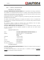
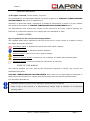
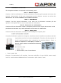
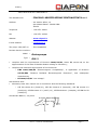
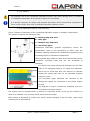
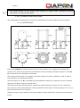
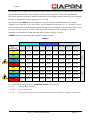
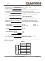
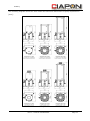
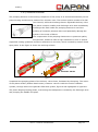
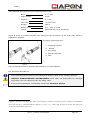
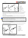
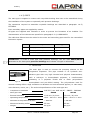
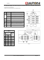
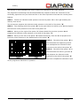
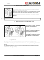
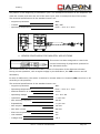
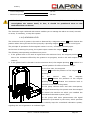
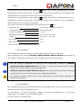
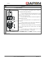
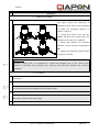
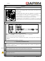
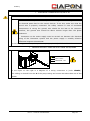
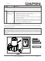
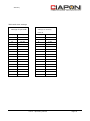
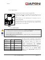
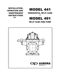
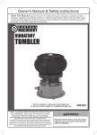
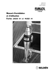
EUR 3 CENTRALIZED LUBRICATION SYSTEM OPERATION AND MAINTENANCE MANUAL Index PART 1 – GENERAL CONSIDERATIONS................................................................................................. 4 OVERVIEW OF THE COMPANY .............................................................................................................. 4 MANUFACTURER'S DATA ......................................................................................................................... 4 CUSTOMER SERVICE ................................................................................................................................. 4 GENERAL WARNINGS ............................................................................................................................... 5 SYMBOL LEGEND ........................................................................................................................................ 5 SCOPE OF THIS MANUAL ........................................................................................................................ 5 HANDBOOK STRUCTURE ......................................................................................................................... 6 SAFETY STANDARDS APPLIED.............................................................................................................. 6 DECLARATION OF CONFORMITY ......................................................................................................... 7 1.1.0) RECOMMENDED USE .................................................................................................................... 8 1.2.0) SAFETY.............................................................................................................................................. 9 1.3.0) DESCRIPTION OF THE SYSTEM ............................................................................................... 9 1.4.0) TECHNICAL SPECIFICATIONS ............................................................................................... 10 1.4.1) ELECTROPUMP ............................................................................................................................. 10 1.4.2) PUMPING ELEMENT ..................................................................................................................... 14 ● SIGNALING VALVE (with recirculation of grease) .................................................................. 16 ● SIGNALING VALVE (with ejection grease) .............................................................................. 16 ● MANOMETER .................................................................................................................................. 17 1.4.3) PIPES .............................................................................................................................................. 18 ● MAIN PIPE ....................................................................................................................................... 18 ● SECONDARY PIPE.......................................................................................................................... 19 1.4.4) DISPENSER ................................................................................................................................... 19 ● DOUBLING OF FLOW RATE ......................................................................................................... 25 ● BRIDGE OUTPUT CONNECTION ................................................................................................. 26 ● INDICATOR PULSE OF VISUAL INSPECTION .......................................................................... 26 1.4.5) FITTINGS ....................................................................................................................................... 26 ● RECYCLABLE FITTING .................................................................................................................. 27 ● QUICK FITTING ............................................................................................................................. 28 ● EXTENSIONS .................................................................................................................................. 29 1.4.6) TIMER ............................................................................................................................................. 30 ● PAUSE/WORKING CYCLE ............................................................................................................. 31 ● PAUSE/SENSOR WORKING CYCLE ............................................................................................ 31 1.4.7) SENSOR CONTROL WORKING DISTRIBUTORS ..................................................................... 31 ● SENSOR CODE 095032 FOR AUTOMOTIVE APPLICATIONS................................................. 31 ● SENSOR CODE 095010 FOR INDUSTRY APPLICATIONS ...................................................... 32 1.4.8) MINIMUM LEVEL .......................................................................................................................... 33 Industry 1.5.0) STORAGE ........................................................................................................................................ 34 1.6.0) ASSEMBLY ..................................................................................................................................... 34 1.6.1) OPERATING PROCEDURE ........................................................................................................... 35 ● ELECTROPUMP ............................................................................................................................... 36 ● PUMPING ELEMENT ....................................................................................................................... 37 ● FITTINGS ......................................................................................................................................... 37 ● DISPENSER ..................................................................................................................................... 38 ● SENSOR........................................................................................................................................... 38 ● MAIN AND SECONDARY PIPES ................................................................................................... 38 • ELECTRICAL CONNECTION 12/24 V DC ................................................................................... 39 • VERSION WITHOUT TIMER OR WITH TIMER PAUSE/WORK ............................................ 39 • VERSION WITH TIMER PAUSE/SENSOR ............................................................................... 39 • VERSION WITHOUT TIMER OR WITH TIMER PAUSE/WORK AND MINIMUM LEVEL .... 40 • VERSION with TIMER PAUSE/SENSOR and MINIMum LeVEL .......................................... 40 • electrical connection 110/220 V AC ...................................................................................... 41 • VERSION WITHOUT TIMER OR WITH TIMER PAUSE/WORK ............................................ 41 • VERSION WITH TIMER PAUSE/SENSOR ............................................................................... 42 • VERSION without TIMER Or with TIMER PAUSe/work and MINIMum LeVEL ............... 42 • VERSION with TIMER PAUSe/SENSOR and MINIMum LeVEL .......................................... 43 • remote control device............................................................................................................... 43 1.6.2) WIRING DIAGRAM VERSION 12/24 V DC .............................................................................. 44 VERSION WITHOUT TIMER OR WITH TIMER PAUSE/WORK ................................................ 44 VERSION WITH TIMER PAUSE/SENSOR .................................................................................. 44 1.6.3) WIRING DIAGRAM VERSION 110/-220 V DC ........................................................................ 45 VERSION WITHOUT TIMER OR WITH TIMER PAUSE/WORK ................................................ 45 VERSION WITH TIMER PAUSE/SENSOR .................................................................................. 46 PART 2 – OPERATING MANUAL .................................................................................................................. 47 2.1.0) COMANDS ...................................................................................................................................... 47 2.2.0) TIMER PROGRAMMING ............................................................................................................ 48 2.3.0) TANK FILLING .................................................................................................................................. 51 2.3.1) LUBRIFICANTS ............................................................................................................................. 51 2.4.0) START-UP ...................................................................................................................................... 52 2.4.1) OPERATING PROCEDURE ........................................................................................................... 52 PART 3 – MAINTENANCE INSTRUCTION ............................................................................................ 53 3.1.0) MAINTENANCE INSTRUCTION .............................................................................................. 53 Part 1 – General considerations Page 2 Industry 3.2.0) SCHEDULED MAINTENANCE ................................................................................................... 53 3.3.0) ANOMALIES .................................................................................................................................. 54 Part 1 – General considerations Page 3 Industry PART 1 – GENERAL CONSIDERATIONS OVERVIEW OF THE COMPANY CIAPONI LUBRIFICAZIONE CENTRALIZZATA s.r.l. is specialized in the design, manufacture and installation of centralized lubrication points. The company, which initially produced industrial vehicles only, has developed in the years, thanks to the vast experience acquired, earth moving machines and machinery for industrial applications. Its dynamism has led it to upgrade its engineering, manufacturing and quality control systems with state-of-the-art solutions. The Quality Control System adopted by the company was certified, in 2001, as compliant with the requirements of standard UNI EN ISO 9002 by the certification body named Det Norske Veritas Italia s.r.l.. The company's mission is supply its customers with a full assistance, from the supply, installation of dependable products down to on-site maintenance. CIAPONI LUBRIFICAZIONE CENTRALIZZATA s.r.l., is a leading Italian company, with over 35 years of experience that has gradually expanded its market and now serves several European customers. MANUFACTURER'S DATA Name - CIAPONI LUBRIFICAZIONE CENTRALIZZATA s.r.l. Address - Via Vittorio Alfieri, 10 – San Miniato Basso 56028 – Pisa ITALIA Telephone - +39 0571 42661 Fax - +39 0571 42244 Web site - www.ciaponi.it E-mail address - [email protected] Tax-payer code/VAT no. - IT01160480503 CUSTOMER SERVICE CIAPONI LUBRIFICAZIONE CENTRALIZZATA s.r.l. follows its customer directly by means of its post-sale servicing. To request further information or order spare parts, it is possible to contact the Customer Service at the phone/fax numbers listed above. Part 1 – General considerations Page 4 Industry GENERAL WARNINGS © All rights reserved. Fourth edition, July 2013. This Maintenance and Operation Manual has been prepared by CIAPONI LUBRIFICAZIONE CENTRALIZZATA s.r.l. and is supplied as is. Therefore, it cannot be copied, reproduced, circulated or transcribed, in whole or in part, without the written authorization of CIAPONI LUBRIFICAZIONE CENTRALIZZATA s.r.l.. The Manufacturer may change the content of this manual at any time, without warning, for technical or commercial reasons or to comply with new standards or laws. SYMBOL LEGEND Key to symbols for the correct text interpretation The symbols listed will be reported to the left of the text or in the vicinity of contents to which the reader should pay attention. Prohibition signal: it prohibits an action that could cause a hazard. Prescription signal: it prescribes specific behavior. Warning signal: it warns of a risk or generic danger. Electrical warning signal: it warns of a risk or danger of contact with electrical parts. Education signal: it feels you follow the instructions on the side. SCOPE OF THIS MANUAL This manual supplies the user with all the information required to install, use, service and dismantle the system. CIAPONI LUBRIFICAZIONE CENTRALIZZATA s.r.l. shall not be responsible for damages or faults caused by the failure to comply with the warnings and instructions provided below. It is therefore advisable to: • Carefully read all the parts of the Operation and Maintenance Manual. • Keep a copy of the manual in a safe place and always make it available to all operators working with it. Part 1 – General considerations Page 5 Industry HANDBOOK STRUCTURE The Complete Handbook is composed of the following parts. Part 1 – General aspect Consists of all the information of product presentation, describing the purpose and scope, the technical characteristics of the main components and the different versions, as well as the directions for the correct installation of centralized lubrication. Part 2 – User Manual Consists of all the general information is the entire set of information necessary for the operation of the plant and for correct control and use of the same. Part 3 – Instruction for maintenance Consists of all the information needed to adequately perform some simple maintenance. In this part there are also some very useful information in the event of a malfunction. Part 4 – Spare parts Consists of all the information necessary for the management of spare parts. SAFETY STANDARDS APPLIED Centralized lubrication systems are designed, manufactured and installed in accordance with the requirements set forth in Directive 2006/42/EC. Therefore, for the purposes of the EC marking implant, that is placed in the position shown in Figure 1, adhesive is applied to a metal plate, as shown in figure 2, and in which are contained the following information: Manufacturer's data Figura 2 • • Model / Type • Serial number / Year of manufacture Figura 1 Power supply data Example of a metal plate for EC marking of a pump model Euro 3, type 150302, power supply 24 V DC, serial number 038646 and lot of construction 11/06 (month / year). Part 1 – General considerations Page 6 Industry DECLARATION OF CONFORMITY CIAPONI LUBRIFICAZIONE CENTRALIZZATA s.r.l. The Manufacturer - Address - Via Vittorio Alfieri, 10 San Miniato Basso - 56028 PISA ITALIA Telephone - +39 0571 42661 Fax - +39 0571 42244 Website - www.ciaponi.it E-mail address - [email protected] Tax-payer code/VAT no. - IT01160480503 Declare that the machine: • Model - Elettropompa Type - EUR 3 complies with the requirements of Directive 2006/42/EC, Annex II, section A, on the approximation of the laws of Member States relating to machinery; • complies with essential requirements of the Directives: o EMC 2004/108/EC "Electromagnetic Compatibility", in application of Directive 95/54/EEC "Measure Radiated Electromagnetic Emissions", and subsequent amendments; o BT 2006/95/EC "Low Voltage". Also declares that: • laboratory tests were carried out in accordance with the following standards: o CEI EN 61000-6-4 (2002/10), CEI EN 61000-6-2 (2000/02); CEI EN 61000-3-2 (2002/04); CEI EN 61000-3-3 (1997 / 12), CEI EN 60204-1 (1998/04), CEI EN 50178 (1999/03); San Miniato Basso lì, July 2013 Il Legale Rappresentante Ciaponi Lido Part 1 – General considerations Page 7 Industry It is useful to remember that the Declaration of Conformity is valid only if: • The indications, safety warnings and instructions given in the operation and maintenance manual are observed. • The system is used in accordance with the instructions provided by the manufacturer. • Adjustment operations are carried out by authorized, trained and qualified personnel. • Maintenance operations are carried out by qualified and authorized technicians. Failure to comply with the requirements listed in the Certificate of Conformity shall automatically invalidate the warranty. 1.1.0) RECOMMENDED USE Centralized lubrication systems are designed to automatically lubricate points subject to wear, after their identification. Therefore, they must be used only for the lubrication of the points to which they are connected. • Users are not allowed to apply unauthorized changes to an installed system. Modifications must be carried out or authorized by the manufacturer only. • The system should always be used within the operating parameters specified in paragraph 1.4.0) TECHNICAL SPECIFICATIONS. • The system must be used only with the fluids listed in paragraph 2.3.1) LUBRICANTS. • The Technical Department of CIAPONI LUBRIFICAZIONE CENTRALIZZATA s.r.l. can be contacted for further information or feasibility studies. The manufacturer shall not be responsible for damages originating from an improper use or the unauthorized modification of the system or its components. Furthermore, the manufacturer shall not be responsible for damages originating from the use of non original spare parts or parts not certified by the manufacturer, or for damages originating from the use of lubricants other than those listed. Part 1 – General considerations Page 8 Industry 1.2.0) SAFETY • An improper use of the centralized lubrication system may cause damage due an excessive or inadequate lubrication of the points to which it is connected. • It is always necessary to comply with accident prevention and environmental regulations in force in the country where the centralized lubrication system is used. 1.3.0) DESCRIPTION OF THE SYSTEM Figure 3 shows a schematics of the centralized lubrication system in its basic configuration. The system comprises the following units: A – Electropump with tank B – Main pipe C – Multiple way dispenser D – Secondary pipes Centralized lubrication systems significantly reduce the maintenance costs of the equipment on which they are installed, lowering downtime for maintenance operations and increasing the life of lubricated components. These systems also enable to reach all the points that require lubrication, including those that are not accessible to operators. Figure 3 If is active, the pump conveys the lubricant into the main pipe of the pumping element, to supply the dispenser, which has to divide and dose the amount of lubricant among the points that have to be lubricated because subject to wear. The secondary pipes distribute the lubricant to the fittings the replace the lubricators in the points subject to wear. The diagram in Figure 4 shows the operating cycle of a Figure 4 centralized lubrication system. The system can be operated both in manual or automatic mode, driven by the machine on which it is installed or by a control timer fitted inside the pump. Each system is identified by means of a serial number stamped on the EC label, under serial number/year of manufacture. Part 1 – General considerations Page 9 Industry • The serial number of the system must always be quoted when requesting technical information or ordering spare parts. 1.4.0) TECHNICAL SPECIFICATIONS The paragraphs that follow list the technical specifications of each component of the system. 1.4.1) ELECTROPUMP Figure 4 Electropump EUR 3 is a piston pump driven by an eccentric cam, designed to operate with grease or oil, that can be used with a maximum of three pumping elements (Figure 5 ref. A, B, C) connected to the lubrication centralized. The housing of the pump is a compact monobloc element in plastic, shaped in order to offer a full resistance to mechanical stresses. The tank (figure 5 ref. D) is transparent polycarbonate molded for versions 2 liter and modular (figure 5 ref. E) for versions 4 and 8 liters. The filling of the tank takes place by means of a special lubricator (figure 5 ref. F) situated in the front part of the pump body for versions grease and through a screw cap (figure 5 ref. G) on the top of the tank for oil versions. Adhesive straps on the outside of the tank enable to easily identify the minimum and maximum levels. Part 1 – General considerations Page 10 Industry The shaped roller system and windscreen wiper enable to eliminate air bubbles from the grease contained inside the tank, thus ensuring a trouble-free operation also at low temperatures. The worm reduction gear with helical wheel and DC low voltage electric motor can be controlled directly or through the control timer(figure 5 ref. H). The electric model EUR 3 can be supplied in various versions characterized by the supply voltage (12 to 24 V DC; 110 ÷ 220 V AC), by the capacity of the tank (2 ÷ 4 ÷ 8 liters), by the control system with or without timer programming, by the presence or less of the sensor end of the cycle, by the presence or less of the warning of minimum level of grease in the tank. Electrical connections are made through wired systems (Figure 5 ref. I). TABLE A lists the codes of all the models of supply pumps. Table A Capability Pause / Operating Timer Pause / Sensor Timer 8 liters 12V 150102 150104 150108 150152 150154 150158 150202 150204 150208 24V 150252 150254 150258 150302 150304 150308 150352 150354 150358 110V 150402 150404 150408 150452 150454 150458 150502 150504 150508 220V 150552 150554 150558 150602 150604 150608 150652 150654 150658 12V 160102 160104 160108 160152 160154 160158 160202 160204 160208 24V 160252 160254 160258 160302 160304 160308 160352 160354 160358 110V 160402 160404 160408 160452 160454 160458 160502 160504 160508 220V 160552 160554 160558 160602 160604 160608 160652 160654 160658 Oil 2 liters 4 liters 8 liters 2 liters 4 liters 8 liters 2 liters 4 liters Voltage Grease Without Timer For versions with optional device MINIMUM LEVEL code becomes: • 1 5 1 ...... for all grease versions • 1 6 1 ...... for all oil versions • 1 7 1 ...... device press grease only grease version with tank 4 liters and supply voltage 24V Part 1 – General considerations Page 11 Industry The technical specifications for electropump EUR 3 are listed below: - Operating temperature From – 30°C to + 80°C - Number of outlets 1, 2 or 3 - Pumping system Ø 6 mm piston, driven by eccentric cam - Connection of main pipe Quick fitting, for Ø 6 mm pipe - Tank capacity 2, 4, 8 liters with maximum and minimum level indicators - Lubricant Grease up to consistency grade NLGI 2 Oil 50 – 1000 cST 40°C - Tank filling With lubricator A M10x1 UNI 7663 - System for the removal of air bubbles Rotating cylinder and windscreen wiper - Capacity per outlet See pargraph 1.4.2) Pumping element - Reduction gear Worm, with helical wheel and DC shielded electric motor • Rated voltage 24 V DC ; 12 V DC • Rated absorption 24 V DC – 0,5A ; 12 V DC – 1 A • Max pickup absorption 24 V DC – 3 A ; 12 V DC – 6,5 A • Speed 22 rpm - Power supply • 12 V DC ; 24 V DC ; 110/220 V AC – 50 Hz Rated absorption: 220V AC 0,1 A 110V AC 0,2 A - Protection class IP65 - Control system None, Timer or Timer and Sensor - Device minimum level Optional for all versions TABLE B is shown for each model, the empty weight of the pump in standard configuration with a single pump installed: Table B GREASE OIL Lubricant Tank capability Weight 2 liters 3,3 kg 4 liters 4,8 kg 8 liters 5,5 kg 2 liters 3,6 kg 4 liters 5,1 kg 8 liters 5,8 kg Part 1 – General considerations Page 12 Industry The following diagram shows for each model the maximum dimensions of pump expressed in [mm]: Figure 5 Part 1 – General considerations Page 13 Industry 1.4.2) PUMPING ELEMENT The pumping element is the working component of the pump. It is shrunk-fitted directly on the pump housing and driven by means of an eccentric cam. The suction system consists of a dual free channel, while the discharge has an adjustable delivery valve. The piston contains a safety and discharge valve that immediately discharges the fluid inside the pumping element to avoid the building of excessive pressure that could potentially damage the system in the event of failure. Figure 6 The components of the pumping element are in premium quality alloyed steel, treated to offer a high resistance to wear. A special superficial coating guarantee excellent resistance to corrosion, which is tested by means of salt spray tests. In the figure is shown the working scheme. CAM A PISTON A OUTLET VALVE B Figure 7 Completed the pumping phase of the delivery valve closes, facilitated by the spring. The return of the piston at BDC (bottom dead center) creates a vacuum inside the suction chamber cylinder, through which the lights A is filled with grease, Figure 8 left highlighted in light blue. The piston begins pumping phase, overcoming the backpressure created by the discharge valve and pumping the fat B in the plant. Part 1 – General considerations Page 14 Industry The technical specifications of the pumping element are: - Bore Ø = 6 mm - Useful stroke 6 mm - Capacity 0,17 cm3 - Flow rate 1 ~2,8 cm3/min - Weight 250 gr - Safety valve Pmax = 250 ± 50 bar - Fitting Standard with G1/4” threading Figure 8 shows a pumping element with fitting for the connection of the main pipe, which is supplied as standard. The main components are: 1. Pumping element 2. Washer 3. 90° fitting 4. Manual lubricator 5. Cap Figura 9 Every pumping element is adjusted and tested by the manufacturer. It is therefore advisable to: • Avoid changing the set points of the safety and delivery valve of the pumping element. • CIAPONI LUBRIFICAZIONE CENTRALIZZATA s.r.l. shall not responsible for damages originating from the tampering with the safety valve. • 1 In the event of problems, immediately contact the Customer Service. Warning - the flow value mentioned relates to the following conditions: lubricating grease consistency class NGLI2 or oil 50-1000 cSt 40 ° C, standard ambient conditions (T = 20 ° C, p = 1atm), back pressure of 100 bar and motor from 20 rpm and rated voltage 12/24 V DC. Part 1 – General considerations Page 15 Industry ● SIGNALING VALVE (with recirculation of grease) Figure 9 shows a version of the pumping element, which can be supplied as optional, with an external signaling system that controls the inlet instead of the safety valve with recirculation of grease. The components shown are: 1. Pumping 2. Washer 3. 3 way shunt 4. Signaling valve 5. 90° fitting 6. Manual lubricator 7. Cap Figura 10 In orinary operating conditions, the external signaling valve is located in the inactive position (OFF – Spin down). At the moment in which the pressure output from the pump reaches the value of 250 bar, the valve moves progressively in signaling position. (ON – Spin high). After you restore the correct functioning of the system is necessary to verify that the indicator has returned to normal operating position. In the event of overpressure circuit, the grease falls into the pump from the pumping itself. • • Do not modify or remove the safety valve outside. CIAPONI LUBRIFICAZIONE CENTRALIZZATA s.r.l. disclaims any liability for damage caused by tampering with the safety valve outside. • In case of malfunction of the safety valve outside immediately contact Customer Service. ● SIGNALING VALVE (with ejection grease) Figure 11 shows a version of the pumping element, wich can be supplied as optional, with an external signaling system that controls the inlet instead of the safety valve with ejection grease. Part 1 – General considerations Page 16 Industry The components shown are: 1. Pumping 2. Washer 3. 3 way shunt 4. Signaling valve 5. 90° fitting 6. Manual lubricator 7. Cap Figura 11 At the moment in which the pressure output from the pump reaches the value of 250 bar, the valve moves progressively in signaling position. (ON – Spin high). The centralized lubrication system is downloaded with grease leakage. After you restore the correct functioning of the system is necessary to verify that the indicator has returned to normal operating position. In the event of overpressure circuit, the grease falls into the pump from the pumping itself. • • Do not modify or remove the safety valve outside. CIAPONI LUBRIFICAZIONE CENTRALIZZATA s.r.l. disclaims any liability for damage caused by tampering with the safety valve outside. • In case of malfunction of the safety valve outside immediately contact Customer Service. ● MANOMETER • Figure 12 shows the version of the pump, supplied as optional on request, with manometer for measuring the pressure delivered. The components shown are: 1. Pumping 2. Washer 3. 3 way shunt 4. Manometer 5. 90° fitting 6. Manual lubricator 7. Cap Figura 12 Part 1 – General considerations Page 17 Industry 1.4.3) PIPES The main pipe is supplied in meters with recyclable bushing that have to be assembled during the installation of the system or optionally with pressure bushings. The operations required to assemble recyclable bushings are described in paragraph 1.4.5) FITTINGS. Even secondary pipes are supplied by meters. All pipes are supplied with lubricant in order to prevent the formation of air bubbles. The characteristics of the lubricant are specified in paragraph 2.3.1) LUBRICANTS. The table that follows lists the codes for the main and secondary pipes used for the centralized lubrication system. Code Description Lenght 00630 Main pipe R7 – 3/16 By meters 00760 Main pipe R7 – 1/8 By meters 097000 Secondary pipe ø6x1,5 By meters IMPORTANT: To order a main pipe with pressure bushings, use the code 00630/00760 associated to the description pressure bushings and indicate a length in millimeters. ● MAIN PIPE The main pipe is used to connect the pumping element to the progressive dispenser. This pipe consists in an hydraulic antiabrasive pipe with very high chemical and physical characteristics, with a sub-layer consisting Figura 13 in 2 in thermoplastic polyester braids polyester, and in a reinforcement black polyurethane thermoplastic and pre-drilled coating. The polyurethane used for external coating offers a high resistance to abrasion and environmental agents (i.e. salt water, micro-bacteria, ozone, etc.). The technical specifications of the main pipe are: - Compliant to standards SAE J517, sez. SAE 100 R7 – EN855 – ISO3949 - Main pipe code 00630 00760 - External diameter 3/16 inch / 9,6 mm 1/8 inch / 8,2 mm - Operating temperature from – 40°C to + 93°C from – 40°C to + 93°C - Minimum brust pressure at 20°C ~ 840 bar ~ 840 bar - Minumum bending radius 25 mm 25 mm - Weight 60 gr/m 45 gr/m Part 1 – General considerations Page 18 Industry ● SECONDARY PIPE The 6x1.5 secondary pipe is a type A, single layer pipe in Hytrel elastomeric polyester, compliant with the specifications listed in standards ISO, SAE, DIN, N.F. and UTAC. The technical specifications for the secondary pipe are: Figura 14 - Dimensions Ø 6 mm x 1,5 mm - Operating temperature from – 40°C to + 80°C - Minimum brust pressure at 20°C ~ 150 bar - Minimum bending radius 20 mm 1.4.4) DISPENSER Modular distributors or volumetric dispensers used are progressive dispensers with check valve. They are made of a monobloc steel body containing small pistons in tempered steel, which divide the flow ratebetween the outlets. Elements are sealed by means of high resistance O-Rings. The progressive distributor can be supplied both assembled and disassembled. The number of single dispensing elements which constitute a progressive distributor ranges from a minimum of 3 to a maximum of 10. Figura 15 Part 1 – General considerations Page 19 Industry ● SCREW TIE-RODS FOR DISPENSENSERS (screws UNI5931) TIE-RODS Code 00803 00804 00805 00806 00807 00808 00809 00810 Description Tie-rods for 3 dispensing elements - M6x65 Tie-rods for 4 dispensing elements - M6x80 Tie-rods for 5 dispensing elements - M6x90 Tie-rods for 6 dispensing elements - M6x110 Tie-rods for 7 dispensing elements - M6x120 Tie-rods for 8 dispensing elements - M6x140 Tie-rods for 9 dispensing elements - M6x150 Tie-rods for 10 dispensing elements - M6x170 Part 1 – General considerations Page 20 Industry The table that follows, wich refers to figure 15, lists the codes for the necessary components of a progressive distributors. Codes are also provided for the spare parts. Pos Code A Description 095500 Initial element 095502 Dispensing element 0,05 cm3 095503 Dispensing element 0,10 cm3 095504 Dispensing element 0,25 cm3 C 095505 End element D Da commercio B A1 See the previous table 095020 Gasket set initial element B1 095019 Gasket set dispensing element C1 095527 Outlet cap ----- 095016 Sensor cap Tab. C Dimensions N (mm) Weight (gr) A B 3 79,1 59,1 1230 4 93,8 73,8 1450 5 108,5 88,5 1670 6 123,2 103,2 1890 7 137,9 117,9 2110 8 152,6 132,6 2330 9 167,3 147,3 2550 10 182,0 162,0 2770 Part 1 – General considerations Page 21 Industry TABLE E, which refers to Figure 15, specifies the overall dimensions and the weight of the progressive dispenser without fittings, depending on the number “N“ of dosing elements. The technical specifications of the progressive dispenser are: - Number of dispensers that can be assembled from 3 to 10 - Operating temperature from – 30°C to + 100°C - Operating pressure: min 10 bar - 400 bar max - Max number of cycles per minute 300 - Dispenser flow rate per cycle 0,05 cm3 ; 0,10 cm3 ; 0,25 cm3 - Inlet fitting M10x1 threading - Outlet fitting M10x1 threading By means of the sensor connected to the - Cycle electric control (optional) pause/operating The following diagram describes the operation principle of taking as reference a distributor composed of 3 dispensers. The distribution and the flow rate to the various outputs is determined by the reciprocating indicated with the letters movement "A", of the pistons "B" and "C". With the stretch in black is identifies the flow of pressurized lubricant that determines the movement of the pistons. The progressive distributor is powered by a pumping element of the pump EUR3, to which it is connected through the main pipe. The dashed path identifies the flow of lubricant prepared disbursement. The course identifies the white pipes in which the lubricant is not under pressure. The progressive numbering from 1 to 6 identifies the outputs of which are connected to the secondary pipes that carry the lubricant flow in the flow required to lubricate the various points bearing. Part 1 – General considerations Page 22 Industry The stretch in white identifies the ducts in which the lubricant is not under pressure. The progressive numbering from 1 to 6 identifies the outputs of which are connected to the secondary pipes that carry the lubricant flow in the flow required to lubricate the various points bearing. STEP 1 - The flow of lubricant under pressure moves the piston "A" to the right enabling the delivery from the 1. This movement prepares the lubricant under pressure to the shift of the piston "B". STEP 2 - The resulting shift of the piston "B" to the right allows the delivery exit 4 and prepares the lubricant under pressure to the shift of the piston "C". STEP 3 - Moving to the right of the piston "C" allows allows the provision junction 6 and prepares the lubricant under pressure to the shift of the piston "A". STEP 4 - Moving to the left of the piston "A" allows the delivery from the 2 and prepares the lubricant under pressure to the displacement of the piston "B". STEP 5 - The shift of the piston "B" to the left allows the dispensing exit 3 and predisposes the lubricant under pressure to the shift of the piston "C". STEP 6 - The shift of the piston "C" to the left allows the delivery junction 5 and prepares the lubricant under pressure to the shift of the piston "A" has been completed a lubrication cycle of the progressive distributor in question. Part 1 – General considerations Page 23 Industry ● ASSEMBLY The dispenser must be assembled as shown in Figure 16. The initial element "A" dispensers "B" with the selected capacities, and the end element "C" must be paired correctly positioning the O-ring seal for each item. Tiranti Esempio di distributore composto da n°3 elementi dosatori Elemento iniziale Elementi dosatori num. min. 3 num. max 10 Elemento finale Schema di assemblaggio Dadi Figura 16 In the table below we list the codes of the gaskets needed to assemble a progressive distributor: Code Pos Description 095020 A1 Gasket set initial element 095019 B1 Gasket set dispensing element It is useful to remember that that the number of coupled dispensers can range between a minimum of 3 and a maximum of 10. The tightening torque of the tie rods must be equivalent to 6 Nm (Newton per meter). Part 1 – General considerations Page 24 Industry ● DOUBLING OF FLOW RATE The flow rate of each dispenser can be doubled by means of the internal connection of the two outputs. In this case it sees only one of the two outputs of the dispenser. For each lubrication cycle exit will be paid a nominal flow rate twice that shown on the dispenser. This operation, with reference to Figure 19, is performed by unscrewing the fitting from the side of the written "CX" from the doser to whom one wants to double the flow, phase "A", removing the threaded internal phase "B", and then screwing the plug M10x1, phase "C". Figura 17 IMPORTANT: You cannot close both outputs on the same dispenser. Part 1 – General considerations Page 25 Industry ● BRIDGE OUTPUT CONNECTION This connection system is used when we want to increase the flow of grease or oil, at a point of lubrication. In carrying out this type of operation, you must always keep in mind the grain to the central liaison for doubling the flow rate, which in some combinations should be removed, while others must remain inside the dispenser. In case of malfunctioning of the bridge link or problem about the installation, contact Customer Service immediately. ● INDICATOR PULSE OF VISUAL INSPECTION The movement of the pin, actuated by the piston element on which is mounted the detector, as shown in the figure, allows visual control of the operation of the distributor and then the successful execution of the lubrication cycle. The indicator is constructed in such a way that it can be installed on any metering element of the distributor. 1.4.5) FITTINGS The fittings used for the centralized lubrication system includes both quick fittings and extensions, for secondary pipes with a diameter of Ø 6 mm, and recyclable fittings for the main pipe R7. The paragraphs that follow describe the technical characteristics and dimensions expressed in millimeters for each type of fitting: Part 1 – General considerations Page 26 Industry ● RECYCLABLE FITTING These fittings, which are made in steel or nichel-plated brass, are used to assemble the main pipe. Ø Ø1 CH CH1 6 9,6 10 14 L L Ø1 00591 Descrizione Straight recyclable fitting Ø6 - 3/16” pipe Ø Code 59 CH CH Ø1 L2 Description 90° recyclable fitting Ø6 00592 - 3/16” pipe Ø Ø1 CH CH1 L1 L2 6 9,6 12 57 14 36 CH L1 Code CH Ø Ø Ø1 CH CH1 L1 6 9,6 12 36 14 Ø Description Straight recyclable fitting 00750 Ø6 - 1/8” pipe Ø1 L Code CH CH Description 90° recyclable fitting Ø6 00751 - 1/8” pipe Ø Ø1 CH CH1 L1 L2 6 9,6 10 51 12 36 CH CH L1 Code Ø1 L2 Ø Boccola recuperabile Tubazione primaria 1 Figure 18 show the operations that have to be 2 Inserto recuperabile recyclable fittings. 17 To facilitate and allow a correct assembly of the fitting, it is necessary to grease the internal and external surfaces of the area where the fitting is 3 4 performed to assemble the main pipe with Avvitare in senso antiorario inserted. Avvitare in senso orario Figura 19 Part 1 – General considerations Page 27 Industry ● QUICK FITTING Quick fittings are in nickel-plated brass. The fitting, with conical metrical or gas threading, guarantees maximum sealing without the need of gaskets. B 6 CH L 12 24,5 096016 Straight fitting M8x1, conical 6 M8x1 con. 6 12 23,5 096017 Straight fitting M10x1, conical 6 M10x1 con. 6 12 21 096022 Straight fitting G1/8” 6 G1/8” 7,5 12 21 Code 096021 Ø CH L 6 12 33 CH A CH Ø Ø Description Giunzione Ø L Ø A 6 M6x1 con. B Code Description 096015 Straight fitting M6x1, conical L 096019 90° fitting M8x1, conical 6 M8x1 con. 6 11 16,5 21 096020 90° fitting, M10x1 conical 6 M10x1 con. 6 11 16 21 096023 90° fitting G1/8” 6 G1/8” 7,5 11 17,5 21 Code Description 025030 90° fitting revolving M6X1 Ø A 6 M6x1 con. B 8 CH L1 L2 13 20,5 21,5 025031 90° fitting revolving M8X1 6 M8x1 con. 8 13 20,5 21,5 025032 90° fitting revolving M10X1 6 M10x1 con. 8 13 20,5 21,5 00426 6 G1/8 90° fitting revolving G1/8 7,5 12 21 22 L2 CH Ø L2 21 A L2 Ø L1 17 CH B CH 11 L1 6 B B Ø A 6 M6x1 con. L1 Code Description 096018 90° fitting M6x1, conical A Part 1 – General considerations Page 28 Industry Raccordo ad innesto rapido The quick fitting accelerates the assembly and "Click" disassembly of the system pipes. Tubo Ø6 Spingere Figure 19 shows the operations that have to be performed to quickly assemble and disassemble A B the pipes. Premere Quick fitting pipes can be used both as recyclable Tirare fittings and as pressure bushings for the primary and secondary pipes. Premere D C Figura 20 ● EXTENSIONS The tables that follow provide the codes of the straight and 90° extensions in brass, which can be installed on the secondary pipes of the centralized lubrication system. 00448 Code 00380 00473 00430 extension M8x1 M8x1 con. – M10x1 Straight con. extension M10x M10x1 con. – M10x1 1 con. B1 CH L M10x1 4.5 8 12 20 M10x1 7 6 12 18 L con. – M10x1 M10x1 M8x1 con. 90° extension M10x1 M10x1 con. – M10x1 con. CH A1 B1 Description A 90° extension M6x1 M6x1 con. con. – M10x1 90° extension M8x1 B A Straight B 7 6 12 18 A1 B B1 CH L1 L2 M10x1 7 4 12 20 12 M10x1 7 4 12 20 12 M10x1 7 4 12 20 12 CH A1 Part 1 – General considerations A 00499 A1 B1 00460 Description A Straight extension M6x1 M6x1 con. - M10x1 con. L2 Code B L1 Page 29 Industry The tecnical specifications of filling are: - Operating temperature From – 30°C to + 80°C - Minimum pressure -0,99 bar - Maximum pressure 150 bar - Gas threads Compliance with ISO7.1, BS 21, DIN 2999 - Metric/Conical threading Compliance with UNI 7707 1.4.6) TIMER The timer is located inside the pump housing, in a waterproof area. Its function is to automatically control the centralized lubrication system. Technical specifications for models with Pause/Operation timer, 24 V DC - Operating voltage 20 ÷ 30 V DC - Maximim current load 5A - Short-circuit limitation 7A - Current absorbed in stand-by 30 mA - Current absorbed during the cycle 50 mA (except current motor) - Lamp power 15 W (versions with remote control) - Operating temperature From - 25°C to + 70°C - Storage temperature From - 30°C to + 80°C - Hardware protections • Overload limitation • Polarity inversion • Overheating • Overvoltage (max 45 V) - Type of time memory Digital type EEPROM - Memory life Unlimited - Pause time setting - Working time setting From 5 min to 12 hours through digital programming From 20 sec to 8 min through digital programming WARNINGS: • Power the timer by thoroughly following the instructions provided in 4.1.0) WIRING DIAGRAM. • Do not power the timer with voltages above 35 V to prevent operating problems. Part 1 – General considerations Page 30 Industry ● PAUSE/WORKING CYCLE The control of the working cycle is completely entrusted to the digital programming of the timer. After the pause time set, the system begins a cycle of length equal to the time of scheduled work. The working time must be programmed in such a way that the duration of the lubrication cycle is sufficient to supply all the bearing points connected to it. The time necessary for the completion of a lubrication cycle, can be determined by detaching the secondary pipe from any output of the progressive distributor and measuring the time elapsed between two successive deliveries. In case of difficulty in the determination of working time contact Customer Service. ● PAUSE/SENSOR WORKING CYCLE The cycle control is assigned only to the Timer for programming the pause time. After the pause time set, the system begins the stage of lubrication. A proximity sensor or switch to induction, installed on the progressive distributor, reads the positions of the beginning and end of the cycle automatically stopping the operation of the pump. In case of failure of plant operation, the Timer, after 10 minutes from the drive, it shall stop its operation. A control device remote cod. 110001, consisting of an illuminated push button installed on the control panel of the machine or vehicle, allowing the drive and verify the operation of the lubrication system. In case of difficulty in the determination of pause time contact Customer Service. 1.4.7) SENSOR CONTROL WORKING DISTRIBUTORS ● SENSOR CODE 095032 FOR AUTOMOTIVE APPLICATIONS The sensor code 095032, normally used in the automotive sector, works as a button. Its output is an internal contact. Figura 21 It is used with the Sleep Timer – Sensor. The cycle begins with the contact of the sensor locked: you spent the time programmed pause, the pump enters the stage of work (lubrication). The actuation of the dispenser installed on it opens the contact sensor that reads Part 1 – General considerations Page 31 Industry the position of the beginning of lubrication cycle. The subsequent actuation of the dispenser will close the contact, and then the end of the work cycle, with a consequent stop of the pump. The technical specifications of the standard sensor are: - Degree of protection IP68 - Contact ON / OFF - Operating temperature From – 30°C to + 80°C A ● B SENSOR CODE 095010 FOR INDUSTRY APPLICATIONS This sensor has been designed to control the correct functioning of progressive systems for the Industrial Sector. The sensor checks the movement forward / return of the piston of the dispenser element. During correct operation, with a regular supply by the distributor, the LED turns on and off alternately. In case of malfunction, the sensor is blocked in a state where it is located (LED turned on or off according to the position). The technical specifications of the standard sensor are: - Degree of protection IP67 - Operating temperature From – 25°C to + 70°C - Nominal distance of read 5 mm - Operating voltage 10 ÷ 30 V DC - Hysteresis < 10% mm - Max working frequency 200 Hz - Repeatability < 0,01 mm - Max output current into DC voltage 100 mA - Max load current 200 mA - Short circuit protection Yes - Led indicator Yes - Voltage drop 1,8 V Part 1 – General considerations Page 32 Industry - Loss of amperage 1,8 mV - Maximum pressure 350 bar • N.B.: During maintenance or replacement of the sensor, it is recommended not to over-tighten the sensor itself, in fact, it should be positioned close to the mechanical but not forced. The electronic logic combined with sensor enables you to manage the alarm so visual, acoustic or cause, if necessary, to stop the system. 1.4.8) MINIMUM LEVEL The minimum level of grease in the tank is detected by a magnetic sensor S which detects the position taken during the work of the pump by a pivoting magnet M , as shown in the figure. The principle of operation of the magnetic sensor is to on / off switch, normally open. At the time of starting the pump, the system wiper rotates the magnet M pivoting. The following two operating conditions may occur: 1. if the grease level in the tank is higher than the minimum level, the magnet pivoting M , due to the resistance offered by the grease to its progress, tends to tilt with respect to the vertical; 2. if the grease level in the tank is at the minimum level, the magnet pivoting M remains in a vertical position for effect of its own weight. In the first case, the magnetic sensor S ignores the presence of the magnet M pivoting. In sensor the S pivoting and second case, the magnetic detects the presence of the magnet M indicates the minimum level is reached in the tank of the grease. In the pump without timer and with timer-pause, M S the signal detected by the system must be managed to control the machine on which you installed the centralized lubrication system (PLC). In the pump with timer pause-sensor the signal detected is processed by the timer, which provides Figura 21 to instantly stop the centralized lubrication system, signaling the end of grease to an indicator light. Part 1 – General considerations Page 33 Industry The detection of the position of the magnet M begins with a delay of approximately 20 sec. compared to the drive of the pump. The detection system the minimum level is provided by the manufacturer as an optional and does not provide for adjustment. The detection of the position of the magnet M begins with a delay of approximately 20 sec. compared to the drive of the pump. The detection system of the minimum level is supplied as optional and are not provided for adjuistment. The electro-mechanical characteristics of the magnetic sensor S are: - Mechanical life 100 number of millions of cycles - Switching frequency 250 pulses/second - Precision repeatability 0,1 mm - Operating temperature From - 20°C to + 60°C - Voltage 100 V DC ÷ 150 V AC - Max Power - Max current 10 W * 0,5 A *Do not use inductive loads greater than 0,1 A . 1.5.0) STORAGE The centralized lubrication system is usually supplied disassembled to customers. Before forwarding the system, CIAPONI LUBRIFICAZIONE CENTRALIZZATA s.r.l. adopts all the necessary measures to guarantee a correct packaging of all the components. • The user shall be responsible for storing all the components received by CIAPONI LUBRIFICAZIONE CENTRALIZZATA s.r.l., indoors, in clean and dry rooms and at a safety distance from chemical and/or corrosive substances. • CIAPONI LUBRIFICAZIONE CENTRALIZZATA s.r.l. shall not be responsible for damages originating from the incorrect storage of the components described. • It is useful to remember that the user is fully responsible for a safe loading, unloading and handling of the system. 1.6.0) ASSEMBLY The operating procedure that follows describes the operations that have to be carried out to assembly the centralized lubrication system. For information on overall dimensions, weights and technical specifications of the single components, see Chapter 1.4.0) TECHNICAL DATA . It is also useful to remember that: Part 1 – General considerations Page 34 Industry • These operations must always be performed by trained and qualified technicians • The protection and safety devices fitted on the vehicle or machine should not be modified or disabled. These devices may be removed during the installation of the system, but must be reinstalled after the installation has been completed. • All centralized lubrication systems must be installed away from heat sources. • Centralized lubrication systems should not be installed in particularly aggressive environments with chemicals that could potentially damage the components of the system. • Welding and/or drilling operations required to install the centralized lubrication system must be performed in compliance with the technical specifications of the vehicle or machine manufacturer. • Lubrication systems must be fitted only with the accessories supplied or certified by the Manufacturer. 1.6.1) OPERATING PROCEDURE F Operation 0 Remove all the components of the system from the package. 1 Visually inspect all the components of the system in order to detect potential damages originating from transportation or from an improper storage. All damages should be promptly reported to the Customer Service of CIAPONI LUBRIFICAZIONE CENTRALIZZATA s.r.l. Part 1 – General considerations Page 35 Industry F Operation ● It is advisable to observe the following recommendations: • ALTO Do not install the submerged pump in liquids or on supports with high vibrations. • Do not install the pump next heat sources or close to the electric equipment that could affect the correct operation of the control timer. • 112 2 ELECTROPUMP Do not install the pump in areas with explosive or inflammable mixtures. • N°2 FORI Ø9 0° the figure. • 162 Place electropump EUR 3 in the position shown in Leave at least 100 mm from other equipment or obstacles that prevent access to the pump. • 0° Install the pump making sure that the lubricator for the tank filling and the control timer are easily accessible. • FRONTALE Fix the pump to its support using the Ø 9 mm holes and the 2 M8 UNI5931 – 8.8 screws. Note: it is also possible to use the STANDARD ROD (Code 00610) available as optional on request. Part 1 – General considerations Page 36 Industry F Operation ● 3 PUMPING ELEMENT The system is usually supplied with a single pumping element installed on outlet no. 2. The figure shows the sequence of operations that need to be performed 1 to install the pumping element on 2 outlet 1 and/or 3. • A USCITA N°1 A USCITA N°3 gasket “A” from the outlet where the pumping unit has to be installed. • 3 4 Loosen and remove the cap with Insert and tighten the pumping element in the selected configuration “B”. • B Tighten the pumping element with a torque of 20 Nm. B ATTENTION: the position of the driving cam may hinder the tightening of the pumping element. In this case, it is necessary to install the pumping unit on one of the other outlets or introduce the pumping unit, making sure that the threads are correctly arranged. ● 4 FITTINGS Remove the lubricators from the bearing points of the automatic system that require lubrication. 5 Tighten the fittings of the bearing points. NB: use extensions for the fittings if difficulties arise due to the lack of space or the incorrect positioning of fittings on the bearing points. 6 Tighten the fittings of the dispenser that has to be used. NB: the dispenser is generally supplied without the outlet caps required for the dispensers. Otherwise, remove the screw caps. 7 Tighten the inlet fitting of the dispenser where the main pipe has to be connected. Part 1 – General considerations Page 37 Industry F Operation ● 8 DISPENSER Install the dispenser leaving a distance of at least 50 mm from equipment and obstacles that could prevent the access to the fitting of pipes. For models with sensor, place the dispenser in a position that A allows the cables to be easily connected to the electropump. Fix the dispenser to the frame or crossbeams so that it is possible to reach the lubricating points of the bearing. B To progressively fix the dispenser to its support, use holes “A” and “B”, located on the initial and final sections of the assembled dispenser, and 3 M6 screws. ● SENSOR 9 A B Only for the version with Pause control timer/Sensor Sensor, code 095032, must be installed only on 0.25 cm3 dispensers. • Remove the screw cap with metal gasket “A”. • Press the small piston until it reaches the limit switch; use a plug with a diameter of Ø6mm. • Tighten the sensor as shown in the figure. ● 10 • • MAIN AND SECONDARY PIPES Cut the pipes to measure at a straight angle using a cutter or a shearing unit. Tagliare le tubazioni a misura con taglio ad angolo retto: utilizzare un taglierino con sistema di taglio a cesoia NB: the pipe length should be calculated taking into account the minimum bending radius and the additional length required for the pipes fixed to mobile parts. 11 Fix the main and secondary pipes using common clips or straps. ATTENTION: do not fix or thread the pipes on vehicle or machine components that could overheat (i.e. exhaust pipes, motor, etc.). 12 Connect the pipes to the fittings. Part 1 – General considerations Page 38 Industry F Operation NB: the main pipe is used to connect the pump to the dispenser; the secondary one is instead used to connect the dispensers to the bearing points that require lubrications. • ELECTRICAL CONNECTION 12/24 V DC • VERSION WITHOUT TIMER OR WITH TIMER PAUSE/WORK 13 The only connection this is the power supply. The Connector A figure shows the WIRING 2P power/sensor code 150050 used for the 1) MARRONE (-) 2) BLU (+) connection. It is derived from the body of the pump marked A. A • VERSION WITH TIMER PAUSE/SENSOR 14 Connettor A 1) Posizione vuota 2) ROSSO / VERDE - Tensione sotto chiave 3) MARRONE - Massa 4) NERO - Pulsante 5) VIOLA - Lampada spia luminosa (max 15 W) A S Connettore S 1) MARRONE (-) 2) BLU (+) The CABLE 2P power/sensor code 150050, derived from the S of the pump body, must be connected to the connector B of the sensor. While derived from the connector to the pump housing must be connected to the electrical supply system and with the light button of the remote control device code 110001 . Part 1 – General considerations Page 39 Industry • VERSION WITHOUT TIMER OR WITH TIMER PAUSE/WORK AND MINIMUM LEVEL 15 Connettor A Connettor S 1) MARRONE (-) 1) MARRONE (-) 2) BLU (+) 2) BLU (+) A S The CABLE 2P power/sensor code 150050 used for the connection is derived from the exit of the pump body marked with A. From the position S is instead derived CABLE 2P minimum level cod. 150051. • VERSION WITH TIMER PAUSE/SENSOR AND MINIMUM LEVEL 16 Connettor A 1) Posizione vuota 2) ROSSO / VERDE - Tensione sotto chiave 3) MARRONE - Massa 4) NERO - Pulsante 5) VIOLA - Lampada spia luminosa (max 15 W) A S Connettor S 1) MARRONE (-) 2) BLU (+) The CABLE 2P power/sensor code 150050, derived from the S of the pump body, must be connected to the connector B of the sensor. While the connector (code 150053) derived from the A of the pump casing must be connected to the electrical supply system and with the light button of the remote control device code 110001. The minimum level signal is controlled by the electronic. Part 1 – General considerations Page 40 Industry • 17 ELECTRICAL CONNECTION 110/220 V AC ATTENTION: for the powered versions 220/110V AC - 50Hz ● All electrical components of the system shall be grounded. This applies both to the electrical parts that for the control devices. To do this, make sure that the ground wire is properly connected. For safety reasons in case of accidental disconnection of wiring the ground wire should be the last to be removed: therefore, the ground wire should be about 100mm longer than the phase conductors. ● Connection to the mains supply must be carried out between the electrical wiring of the lubrication system and the power supply a suitably selective differential magneto dimensionat. In the following procedures, always refer to paragraph 1.6.2) WIRING DIAGRAM • VERSION WITHOUT TIMER OR WITH TIMER PAUSE/WORK 18 1) GIALLO/VERDE - Terra 2) BLU - Neutro 3) MARRONE - Fase A In the figure on the right is a diagram of a wiring connection is (code 150052). The cabling is derived from the A of the pump casing and comes with about 600 mm of the sheath. Part 1 – General considerations Page 41 Industry • VERSION WITH TIMER PAUSE/SENSOR 19 Connettor A 1) ROSSO (+) 28-30 V DC 2) Posizione vuota 3) ROSSO/VERDE - Massa pulsante 4) NERO - Pulsante 5) VIOLA - Lampada spia luminosa (max 15 W) 1) GIALLO/VERDE - Terra 2) BLU - Neutro 3) MARRONE - Fase A Connettor S S 1) MARRONE (-) 2) BLU (+) The cable (code 150056) derived from the A of the pump body must be connected to the electrical supply system and with the light button of the remote control device code 110001. The harness comes with about 600 mm of the sheath. The CABLE 2P power/sensor code 150050, derived from the S of the pump body, must connected to the B sensor as for version 12/24 V DC. • VERSION WITHOUT TIMER OR WITH TIMER PAUSE/WORK AND MINIMUM LEVEL 20 1) GIALLO/VERDE - Terra 2) BLU - Neutro 3) MARRONE - Fase Connettore S A 1) MARRONE (-) 2) BLU (+) S The CABLE 2P power/sensor code 150050, derived from the S of the pump body, is what sends the signal to the minimum level. Part 1 – General considerations Page 42 Industry • VERSION WITH TIMER PAUSE/SENSOR AND MINIMUM LEVEL 21 Connettor A 1) ROSSO (+) 28-30 V DC 2) Posizione vuota 3) ROSSO/VERDE - Massa pulsante 4) NERO - Pulsante 5) VIOLA - Lampada spia luminosa (max 15 W) 1) GIALLO/VERDE - Terra 2) BLU - Neutro A 3) MARRONE - Fase Connettor S S 1) MARRONE (-) 2) BLU (+) The cable, derived from the A to the body pump, it must be connected to the electrical supply system and with the light button of the remote control device code. 110001. The harness comes with about 600 mm of the sheath. The Cable 2P power/sensor code. 150050, derived from the S of the pump body, must connected to the B sensor as for version 12/24 V DC. The minimum level signal is controlled by the electronic control. • REMOTE CONTROL DEVICE 22 For versions with control timer pause/sensor, install the luminous indicator of the Remote control device (Cod. 110001) on the control board of the machine or vehicle Dispositivo di controllo a distanza schema collegamento elettrico Cablaggio dispositivo di controllo a distanza pulsante luminoso Mod. A 16 - 1 24 V dc 3) MARRONE - Massa C NO NC It is possible to use both the 12/24 110/220 V V dc ac and remote control device. 2) ROSSO / VERDE - Tensione Sotto chiave per versione Automotive The 4) NERO - Pulsante luminous indicator. 5) VIOLA - Lampada spia luminosa (max 15W) For information on how to wiring figure shows diagram for the the connect the harness to the electropump, see the diagram referred to the selected version and the one below. NB: a lamp with a voltage above 24 V should be used for 110/220 V AC versions. 23 Connect the electropump to the electric system of the vehicle or of the machine on which the lubrication system is installed. Part 1 – General considerations Page 43 Industry 1.6.2) WIRING DIAGRAM VERSION 12/24 V DC VERSION WITHOUT TIMER OR WITH TIMER PAUSE/WORK Schema elettrico pompa 12/24V DC Timer Pausa - Lavoro 12/24V DC M+ Stabilizzatore + Mosfet N + Motore 12/24V DC M Diodo Microcontroller Connettore A Positivo + Blu Blu 12/24V DC Fuse 10A max Negativo Marrone Marrone - M- - Test Enter Presente sono nella versione con Minimo Livello Connettore S + Blu Minimo Livello Blu - Marrone Marrone VERSION WITH TIMER PAUSE/SENSOR Schema elettrico pompa 12/24V DC Timer Pausa - Sensore 12/24V DC Connettore A Posizione vuota + + Blu Negativo Marrone Marrone P+ + Nero Nero L- - Viola Lampada esterna (max 15W) Diodo - - Pulsante esterno M+ Stabilizzatore Viola Mosfet N Blu + M Microcontroller Positivo Blu 12/24V DC Fuse 10A max M- Motore 12/24V DC - Marrone Test Enter + 12/24V DC Minimo Livello Mosfet N Connettore S Sensore Blu + R+ Blu Blu S+ RS- - Marrone Marrone Part 1 – General considerations Marrone Presente sono nella versione con Minimo Livello Page 44 Industry 1.6.3) WIRING DIAGRAM VERSION 110/-220 V DC VERSION WITHOUT TIMER OR WITH TIMER PAUSE/WORK Schema elettrico pompa 110/220V AC Timer Pausa-Lavoro 24V DC Trasformatore 220/110V AC - 24V DC M+ + - Fuse 1,6A max + Stabilizzatore Diodo - Neutro Blu Terra PE Giallo / Verde Mosfet N + M Microcontroller Fase Marrone M- Motore 24V DC - Test Enter Presente sono nella versione con Minimo Livello Connettore S Blu + Minimo Livello Blu - Marrone Marrone Part 1 – General considerations Page 45 Industry VERSION WITH TIMER PAUSE/SENSOR Schema elettrico pompa 110/220V AC Timer Pausa-Lavoro 24V DC Trasformatore 220/110V AC - 24V DC M+ Stabilizzatore + - Fuse 1,6A max + Diodo Neutro Blu - Giallo Verde Terra PE Connettore A + Posizione vuota - Rosso Verde + Nero M- Motore 24V DC - Marrone Test Enter + 28-30V DC PR+ Blu Mosfet N Nero Viola Minimo Livello P+ - Lampada esterna (max 15W) M Rosso Rosso Verde Blu + L+ Rosso Pulsante esterno Mosfet N Microcontroller Fase Marrone RL- Marrone Viola Presente sono nella versione con Minimo Livello Connettore S Sensore Blu + Blu S- - Marrone S+ Marrone Part 1 – General considerations Page 46 Industry PART 2 – OPERATING MANUAL 2.1.0) COMANDS The table that follows describes the command and control devices of centralized lubrication systems with Pause/Operation timer and Pause/Sensor timer. The figure shows the 1 devices installed on the Timer. 2 3 4 The pump of versions without timer are electrically powered by the system that drives them. In this case, start and control instructions are described along with the management and control instructions of the machine where the system is installed. Pos. Type Description 1 Display • It displays the parameters that have been set during the time setting procedure. • 2 Led display The display LEDs turn on in sequence during ordinary operation. This LED turns on when the lubrication system is electrically powered. 3 Button TEST To access the timer, it is sufficient to slightly press it next to "Push". If it is pressed during ordinary operation, it starts the set working cycle after performing a self-diagnostic check. At the end of the working cycle, the timer returns to the Automatic mode. If it is pressed during the timer programming, it enables to scroll the options. 4 Button ENTER • If it is pressed for 3 seconds, it starts the digital programming procedure. • If it is pressed briefly during the programming mode, it enables to change the P (pause) and L (working) values. Part 2 – Operating manual Page 47 Industry Pos. Type Description A remote control system is available as optional for systems with Pause - Sensor timer. This must be installed next to the control panel of the vehicle or the machine where the system is installed. • ----- Luminous indicator, remote This indicator turns on when the centralized lubrication system is powered. It remains on for a few seconds until the timer has completed the initial check and then turns off. control device • It blinks when the pump is running. • It turns on when there is no grease in the tank or if a problem occurs on the system. • If pressed during ordinary operation it starts a work cycle, after performing a self diagnostic test. Upon completion of the cycle, the timer returns to the Automatic mode. 2.2.0) TIMER PROGRAMMING The sections that follow summarize the operations that need to be performed to digitally program the control timer. It is useful to remember that if a power outage occurs, the timer saves the internal data in a digital memory that has no expiry. As soon as power is restored, the timer reloads the saved data and starts counting the time from the point and status in which it had interrupted its operation. 1 - Display 2 – Led display 3 - Button TEST 4 - Button ENTER Figura 23 Part 2 – Operating manual Page 48 Industry N° Activity 01 Consequence Loosen fixing screws “A“ and remove This operation gives access to the timer for digital the cover “B“ to access the timer programming. 02 Press ENTER for 3 seconds The display turns on and shows letter P (Pause). 03 Briefly press ENTER The display shows the value set for parameter P. 04 05 • Press TEST to change the value of parameter P Every time the button is pressed, the displays shows in sequence the digits and letters of the pause time settings shown in the table. Briefly press ENTER to confirm the setting The displayed value is stored as current value for parameter P and the display shows once more letter P. NB. For versions with Pause-Sensor control timer, skip directly to operation 10, because the only parameter that can be set is the pause time P. The display shows letter L (working time). 06 Press TEST to alternate the display of parameters P and L • NB: it is useful to remember that TEST enables to alternate the display of letters P or L. 07 Briefly press ENTER The display shows the value set for parameter L. Every time the button is pressed, the displays 08 Press TEST to change parameter L shows in sequence the digits and letters of the working time settings shown in the table. 09 Briefly press ENTER to confirm the selected setting parameter L and the display shown once more letter L. 10 Press ENTER for 3 seconds 11 The displayed value is stored as current value for Remove cover “B” to access the timer and retighten screws “A“ The display turns off and is ready to run with the new set parameters. The pump is ready to work. ATTENTION - Electropumps with control timers have the following default settings: • Pause P = 8 • Working time L = 2 Part 2 – Operating manual Page 49 Industry Table with time settings • • PAUSE settings for pause P WORK: settings for working times L Display Tempo Display Tempo 0 5 min 0 20 sec 1 10 min 1 40 sec 2 15 min 2 1 min 3 30 min 3 1,5 min 4 1h 4 2 min 5 2h 5 2,5 min 6 3h 6 3 min 7 4h 7 3,5 min 8 5h 8 4 min 9 6h 9 4,5 min A 7h A 5 min B 8h B 5,5 min C 9h C 6 min D 10 h D 6,5 min E 11 h E 7 min F 12 h F 8 min Part 2 – Operating manual Page 50 Industry 2.3.0) TANK FILLING The pump tank is filled by means of lubricator “A”. Remove the cap from the lubricator and fill the tank up to the maximum level (MAX), marked with an adhesive label on the tank. For information on the characteristics of lubricants, see the following paragraph. During the filling of the tank, verify that the air in it is discharged by means of the vent. Make sure that the vent, located on the rear of the tank, is not obstructed Figura 24 2.3.1) LUBRIFICANTS • It is useful to remember that systems manufactured by CIAPONI LUBRIFICAZIONE CENTRALIZZATA s.r.l. are designed to be used with lubrications with a maximum grade of NLGI 2. • Use only compatible lubricants with NBR gaskets. • CIAPONI LUBRIFICAZIONE CENTRALIZZATA s.r.l. supplies the system components that are already lubricated with NLGI 2 lubricant. Family NLGI ASTM penetration at description grade 25°C in 1/10 of mm Fluid greases 000 445 – 475 Semi-fluid 00 400 – 430 0 355 – 385 greases Semi-fluid The table provides comparative data between NLGI (National Lubricating Grease Institute) and ASTM (American Society for Testing and Materials) data only of the ranges used by the systems manufactured by CIAPONI LUBRIFICAZIONE CENTRALIZZATA s.r.l.. For further information on technical data and greases Mild greases 1 310 – 340 safety measures, see the Product Safety Medium greases 2 265 - 295 Sheet (Directive 93/112/EEC) related to the type of lubricant selected or supplied by the manufacturer Part 2 – Operating manual Page 51 Industry 2.4.0) START-UP The operating procedure described below briefly describes the operations that have to be performed to start the system. NB: The following procedure should always be performed when: • During the initial start-up following installation • After every maintenance operation • If the system has not been in operation for a considerable amount of time 2.4.1) OPERATING PROCEDURE N° Activity Consequence Make sure that: 0 1 • All the operations described in Chapter 1.6.0) ASSEMBLY have been performed • All the Pause and Pause/Operation times have been set (for versions with control timer) • The lubricant level in the pump tank is above the minimum level Disconnect one or more secondary pipes Verify that the lubricant reaches the from the bearing lubrication points bearing. Press the manual Start button (TEST) The pump performs one cycle. Repeat the operation described above until 2 the lubricant reaches all the lubrication The lubricant dispensing system is running points of the bearings from which the pipes correctly. have been disconnected 3 • Reconnect the pipes to the bearing lubrication points The system is set in Automatic mode. ATTENTION: if the system is not operating correctly, see Chapter 3.3.0) ANOMALIES Part 2 – Operating manual Page 52 Industry PART 3 – MAINTENANCE INSTRUCTION 3.1.0) MAINTENANCE INSTRUCTION This paragraph provides essential information to allow maintenance technicians to perform ordinary maintenance operation in full safety Before performing any maintenance operation, operators should remember to: • Verify That the system is not running • Check That the electropump has been disconnected from the power supply That the disconnection switch upstream from the electric cubicle has been • Check disconnected All the measures referred to in current accident prevention laws and specifically • Adopt those necessary to signal that servicing operations are in progress. 3.2.0) SCHEDULED MAINTENANCE Due to simplicity of design, robustness and reliability of the components used, CIAPONI LUBRIFICAZIONE CENTRALIZZATA s.r.l. recommends only a limited number of inspections and scheduled maintenance operations. The table that follows lists the checks that have to be performed periodically, along with the frequency and type of operation that the technician must perform to guarantee the efficiency of the system in time. CHECK FREQUENCY Tightening of components After the first 500 Check hours Pipe fixing Operation OPERATION that all components have been correctly tightened. After the first 500 Check that the fittings have been installed of hours Check Every 1500 hours correctly installed the Every 6 months electropump that machine parts have been Check the operation of the electropump with button Test Tank level As required Refill the lubricant in the tank Filling filter Every 2 fills Check and replace (see following paragraph) Part 3 – Maintenance Instruction Page 53 Industry 3.2.1) FILTER REPLACEMENT ONLY GREASE VERSION To service the filling filter of the tank, it is necessary to remove cap “A”, the lubricator “B” and filter “C”. C B Inspect the filter and clean it with compressed air , if necessary. A If the filter is still dirty after being cleaned, replace it. Reassemble filter “C”, lubricator “B” and cap “A”. Tighten the lubricator “B” with a maximum torque of 6 Nm. Figura 25 3.3.0) ANOMALIES This chapter provides information on: • Possible problems that may occur during the operation of the system • The cause that may prevent the system from starting and stopping • Corrective actions NB: the lubrication system with Pause/Sensor control timer has a luminous indicator that can be managed remotely. If the indicator stays on permanently at the end of an operating cycle: • The grease in the tank may have fallen to the minimum level • An anomaly has occurred within the system In both cases, the Timer stops the system even after 10 minutes. N Problem Code 01.01 01 The pump motor Cause Check the power supply and the status No current 01.02 The doesn't work Corrective action electronic of the fuse. card is not Replace the electronic card. working 01.03 The reduction gear doesn't Replace the reduction gear. work 02 02.01 The tank is empty Fill the tank with clean lubricant. 02.02 Air bubbles in lubricant Disconnect the primary tube of the The pump doesn't fitting of the pumping element. Start the delivery lubricant pump manually until the lubricant expelled from the fitting is not perfectly cleaned. Part 3 – Maintenance Instruction Page 54 Industry N Problem Code Cause Corrective action 02.03 Unsuitable lubricant Replace the lubricant with a suitable one 02.04 Pumping unit element blocked Disassemble the pumping element and clean the suction ducts 02.05 Worn pumping element piston Replace the pumping unit 02.06 The delivery valve of the Replace the pumping unit pumping unit is blocked The pump runs, but 03.01 Disconnect pipes Check the status of the pipes and the no lubricant connections to fittings. Replace worn pipes. 03 reaches the bearing lubrication 03.02 The progressive dispenser is Replace the dispenser or clean it. points The lubricant is 04 04.01 The dispenser is not correctly Check that the dispensed amounts are distributed to the connected bearing lubrication lubrication points points irregularly 05 blocked The display LED is to the bearing compliant with those indicated in the system diagram. 04.02 The pause is not correctly set 05.01 The supply voltage is not Verify that the supply voltage ranges correct on between 20V DC and 30V DC, otherwise adjust the supply system. 06.01 The motor is not correctly Check connected to the timer cables that connect the electric motor to the timer and restore connections. The motor doesn't 06 start when TEST is the 06.02 The pressed motor is not working Check that the motor is not short- correctly circuited and that is does not absorb a current above 7A. Replace the reduction gear. The display LEDs 07.01 Faulty motor Contact the Customer Service. 07 alternate but the motor doesn't run The pump starts 08.01 Faulty motor or high output Allow the pump to cool down for a few the greasing phase absorption 08 but doesn't minutes and retry. If the problem reoccurs, contact the Customer Service. complete it immediately Part 3 – Maintenance Instruction Page 55 Sede: Via V. Alfieri, 10 - 56028 S. Miniato Basso (PI) - ITALY Tel. 0039 0571 42661 – Fax 0039 0571 42244 Sito internet: www.ciaponi.it - e-mail: [email protected] Cod. Fis. / Partita I.V.A. n° IT01160480503