1
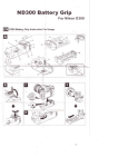
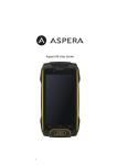
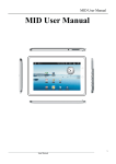
Pure sine wave Inverter&Charger SM SERIES 0612 / 1012 User’s Manual Content of the manual 1. Introduction..........................................................................................................- 3 1.1 introduction of inverter ...............................................................................- 3 1.2 safety instruction .......................................................................................- 3 1.2.1 Common sense .............................................................................- 3 1.2.2 Announcements.............................................................................- 4 1.3 Display and Set .........................................................................................- 5 1.3.1 LED display and Buzzer.................................................................- 5 1.3.1.1 power switch .....................................................................- 8 1.3.1.2 Inverter output ...................................................................- 8 1.3.1.3 Setting mode.....................................................................- 8 2. Install and Operation ............................................................................................- 9 2.1 Install ........................................................................................................- 9 2.1.1 Environment..................................................................................- 9 2.1.2 For connection ground.................................................................- 10 2.2 Installation...............................................................................................- 10 2.2.1 INPUT/OUTPUT..........................................................................- 10 2.3 Installation steps ..................................................................................... - 11 3. AC Mode............................................................................................................ - 11 3.1 transfer time............................................................................................ - 11 4.Battery ................................................................................................................- 12 4.1 Battery capacity.......................................................................................- 12 4.1.1 Estimating Batteries capacity as Requested .................................- 12 4.2 Maintenance ...........................................................................................- 13 4.3 Battery connection...................................................................................- 13 - -1- 4.3.1. Parallel Connection ....................................................................- 13 4.3.2 Series connection........................................................................- 14 4.3.3 Series and parallel connection .....................................................- 14 4.4 Install battery...........................................................................................- 15 4.4.1 Option of battery’s position...........................................................- 15 4.4.2 Manage of installing battery .........................................................- 16 4.4.3Battery connector .........................................................................- 16 5.Technical Specification ........................................................................................- 17 6. Troubleshooting .................................................................................................- 18 7. Service and Support ...........................................................................................- 18 - -2- 1. Introduction 1.1 introduction of inverter SM series inverter is not only an inverter, but also a powerful intelligent charger. SM series inverter can produce continuous standard sin wave to supply power to various loads such as ohmic load (heater), inductive load (air conditioner, fridge), electrical machine (vacuum cleaner), rectifier load (computer) and also as a vehicle-mounted inverter by 12V/24V battery. This series can work long time under high load without reducing rated ratio operation. This intelligent charger adept 3 steps charging which is good to the battery’s longevity. User can set charging current and voltage according to the type and volume of battery. High efficient high power current can do a quick charging. The switch of this inverter can automatically switchover between AC mode and battery mode. When AC is higher or lower than standard power , inverter will switch to battery mode, elsewhere load will stay at AC mode. Transfer period is between quarter-half. Besides, this inverter can also be connected with a motor to prolong the battery life efficiently. Visible and audible LED display and sounder, which can help user to know the status of inverter, battery and AC, so as to judge various breakdown efficiently. SM series is not only an excellent back-up source, but also a UPS for computer. 1.2 safety instruction 1.2.1 Common sense 1. Before using an inverter, please read the warning sign and instruction of inverter and battery. -3- 2. Keep the inverter away from rain, snow and any liquid, the inverter is designed for in-door use; if used in vehicles, keep liquids far away from the inverter. 3. Do not disassemble inverter by yourself, go to the service center when maintenance is needed. Incorrect disassembly or reassembly, will lead to electric shock or fire. 4. To reduce the danger of electric shock, do cut off all the connection before cleaning or repairing. Only shut down the inverter will not prevent you from electric shock. 5. Warning: using lead-acid battery is dangerous, explosive gas will be produced when using. So the room for the battery should be ventilated with out-door environment, ventilating port must be set at the top point to prevent the Hydrogen(H2) stay at the rooftop. 6. Charging the frozen battery is forbidden. 7. Be especially careful when using metal instruments nearby the battery, battery will explode by the sparkle which can be produced when metal instruments touching battery or other electronic parts. 8. Battery choosing should accord to the rated voltage of the inverter which can be read through the Series No. by the last two numbers, for example, the SM1012, SM0612 match 12V. 9. Earth connection: do make sure the earth connection of AC for safety, all the installment should follow the rules and regulations of local country and region. 1.2.2 Announcements 1. When working near the battery, make sure that you can be heard in case of accident. 2. Clean water and soap should be around in case of acid ingredients reaching skin, clothes, or eyes. 3. Equipments for protecting eyes and clothes are needed; do not touch eyes when working near the battery; wash your hands after working. -4- 4. If the battery acid contact with skin or clothes, wash with soap immediately. If eyes contact with acid, rinse with cold water for at least 15 minutes immediately, and seek medical care immediately. 5. Do not smoke nearby the battery or motor to avoid fire. 6. Be especially careful when using metal instruments near the battery, battery will explode by the sparkle which can be produced when metal instruments touching battery or other electronic parts. 7. When operating the battery, private metal things such as ring, bracelet, necklace, watch should be taken away to prevent battery short circuit from contacting with these things. Serious burning can be caused by short circuit. 8. Make sure the inverter and other devices are shut down when doing any maintenance of the system. 1.3 Display and Set 1.3.1 LED display and Buzzer The following picture is the front panel of LED display of inverter, information of battery mode and AC mode can be shown on it. -5- The statements of LED and buzzer(battery 12V system) condition LED1 LED2 LED3 LED4 LED5 LED6 Alarm AC model off off off on off off buzzed only once after swicthing Constant current state off Blink 0.5 sec off on off off Close Pressure constant state off on off on off off Close AC model Full charge floating condition on off off on off off Close Battery Model off off on off off off buzzed only once after swicthing Generator Model off off off Blink 0.5sec off off Close Constant current state off Blink 0.5sec off Blink 0.5sec off off Close Pressure constant state off on off Blink 0.5sec off off Close Generator Model Full charge floating condition on off off Blink 0.5sec off off Close Self-checking conditions off off Blink 0.5sec Blink 0.5sec off off Close Notes Starting up -6- Low battery off off on off on off Blink 0.5sec Blink 0.5sec off on off off on Blink 0.5sec overload 110% off off on off off on Blink 0.5sec close output 15minutes ago overload 120% off off on on off off on Long time buzzing close output 1minute ago Overload 150% off off on off off on Long time buzzing close output at once Battery model output shortcircuit off off on off Off Blink 0.5sec Long time buzzing close output at once Battery model Over temperature off Off on off Blink 0.5sec off Long time buzzing close output 1minute ago AC model Over temperature off Blink 0.5sec off on Blink 0.5sec off Long time buzzing Close charge Over charge current off Blink 0.5sec off on off on Long time buzzing close output and charge at once System fault off off off off off on Long time buzzing close output at once Battery model Battery over voltage -7- 1.3.1.1 power switch Ensure inverter and battery have been installed exactly, please press this button after the buzzer buzzing 3 seconds, start the inverter; When the inverter is running, press the button after the buzzer buzzing 3seconds ,close the inverter. 1.3.1.2 Inverter output In battery mode (Inverter mode), when there is no load, output voltage was 0v, once the load over 12w, inverter will recover to 220V output 1.3.1.3 Setting mode SW1 SW2 SW3 Statues 0 0 0 AC mode charging 10A 0 0 1 AC mode charging 20A 0 1 0 AC mode charging 30A 0 1 1 AC mode charging 40A 1 0 0 Generator mode charging 10A 1 0 1 Generator mode charging 20A 1 1 0 Generator mode charging 30A 1 1 1 Generator mode charging 40A -8- Note: Please setting the charge current according to the capacity of battery , if charge current too high, battery will be very hot and will short the battery life, If the battery capacity was small ,please setting the charge current to the min at first; If input power was generator, please setting the mode in generator mode. Battery charge process: Process Three step :CC Boost CV Float Charge step and transfer define T0 = Start to finish. (invariance current ) T1 = 10 x T0(invariance voltage) min 1h, Max 12h Charge voltage @ 25℃ Clients can setting the invariance voltage and floating voltage according to battery 2. Install and Operation 2.1 Install 2.1.1 Environment Inverter is a minutely electronic equipment ,we should take care of it. It is working environment was different as normal equipment ,like battery, generator ,washing machine . It is a more complex equipment ,which is same type as TV, PC. The inverter design with Copper PCB, metal component and stainless steel screw and so on, can be working in badly environment ,but , if the environment -9- over the specification, due to the humidity and other effect from environment ,the component will be short of life, and this situation was not in warranty. Note: The best install environment is far from hot temp. and humidity place, the worst place for install this inverter is near sea. we suggest that client install the inverter near the battery, the more short cable between inverter and battery , the lower wastage in the power, but , never put the inverter together with the airproof battery, the airproof battery will bring H and O, which may cause fire .don’t install the inverter in the sealed environment .keep air flowing can keep the high efficiency for inverter working. 2.1.2 For connection ground We have connected the inside parts and metal cabinet to the ground ,please make sure the input cable fix. 2.2 Installation 2.2.1 INPUT/OUTPUT AC Input Power Cord Battery input cord Output socket - 10 - 2.3 Installation steps ●step1 Wire the unit from the battery(positive and negative poles) to the utility power source, and then to the AC load. Confirm all wiring is correct and terminal is tig. ●step 2 Check all the voltage rating is correct. Turn on the power switch. ●step 3 Press the on/off button. The system will start working after a few seconds. If the utility power fails the unit will work in battery mode. If not, the system will switch to charging mode and deliver energy to load and battery. 3. AC Mode When utility power is normal, the inverter will work in bypass mode and charge the battery 3.1 transfer time The transfer time from AC mode to battery is 10+/-4ms. - 11 - 4.Battery 4.1 Battery capacity The battery is the power sources of inverter, larger capacity battery can offer longer back up time for inverter. An undersized battery bank results in reduced battery life and system performance. Batteries should not be regularly discharged to the limit of more than 50% of their capacity. Under extreme conditions, such as a severe storm or a long utility outage, cycling to a discharge level of 80% is acceptable. Totally discharging a battery may result in permanent damage and reduced life. 4.1.1 Estimating Batteries capacity as Requested In order to determine the proper battery capacity, it is necessary to compute the number of amp hours that will be used during charging cycles. When the required amp hours are known, the expected amp hour usage ensures to be twice as this amount. Doubling the expected amp hour usage ensures that the batteries will not be overly discharged and extends battery life. To compute total amp hours usage, the amp hour requirements of each appliance that is to be used is determined and then added together. If we know the load capacity w and battery voltage V and the needed back up time T ,We can calculate the battery discharge current I as follow: I =W/V So AH=I*T=W*T/V So Needed battery capacity was 2W*T/V Motors are normally marked with their running current rather than their starting current. Starting current may be three to six times running current. Manufacturer's literature may provide more - 12 - accurate information than the motor nameplate. For larger motors, increasing the battery size indicates that the high demand for start-ups should be required. 4.2 Maintenance Regular Check the condition of battery connection monthly (please refer to the users’ manual of the battery for more details of the battery maintenance), Check the battery interconnections for tightness and corrosion. If any corrosion is found to disconnect the cables, clean them with a mild solution of baking soda and water. DO NOT ALLOW THE SOLUTION TO ENTER THE BATTERY. Rinse the top of the battery with clean water when finished. (Replace the caps first.) To reduce the amount of corrosion on the battery terminals, coat them with a thin layer of petroleum jelly or anti-corrosion grease available from automotive parts stores or battery suppliers. Do not apply any material between the terminal and the cable lugs, the connection should be metal to metal. Apply the protective material after the bolts have been tightened 4.3 Battery connection Battery banks of substantial size can be configured by connecting several smaller batteries. There are three ways to do this. Batteries can be connected in parallel, series, or series -parallel. 4.3.1. Parallel Connection Batteries are connected in parallel when all of the positive terminals of a group of batteries are connected, and then all of the negative terminals of a group of batteries are connected. In a parallel configuration the battery bank has the same voltage as a single battery and a amp/hour rating equal to the sum of the individual batteries. This usually is done only with 12 voltage battery -UPS - 13 - systems. 4.3.2 Series connection Battery series connection is connected the plus plate of one battery to another battery’s negative plate, one by one. The AH of the series connection batteries is the same as the single battery not been connected. And voltage of the series connection batteries is the sum voltage of all the batteries connected. This usually been used in 24V battery inverter system. 4.3.3 Series and parallel connection This is the connection mode combine with the above two, can improve the voltage and capacity of the connected batteries. This usually connects some low voltage and capacity batteries into a high voltage and capacity battery, Common in all battery inverter system. - 14 - 4.4 Install battery Noted: Please be careful when operate, cause it’ll generate a very high current while battery short circuit. Carefully read the users’ manual before install the inverter and battery in order to ensure the safety. 4.4.1 Option of battery’s position Keep the battery close enough to the inverter, but can’t impede in cutting off the inverter. Better to put the battery in left side, because DC electrical terminal of the inverter is in the left side too. Don’t put the inverter and the not sealed battery together in a closed room in order to protect the inverter from corroding by gas generated from battery. This will reduce span of the inverter. The wire connected the battery and the inverter no need too long. The 4/0 AWG wire which used in 12V DC voltage system doesn’t exceed 5 feed. The 4/0 AWG wire which used in 24V DC system doesn’t exceed 10 feet. This is concise and reduces power loss. - 15 - 4.4.2 Manage of installing battery In order not to touch by un-training people, the battery must be store in a well-ventilated and locked case or room. Furthermore, install the battery in the high position, where can connect the battery to outdoor ventilation equipment, in order to prevent the gas which is generated by battery charging from piling up. And still need to set an air intake in a low position to let the air fully flow. For most of the equipment, it’s enough to prevent the hydrogen from piling up with a 1 inch diameter ventilation conduit. And a declining coping can help to emit the air and prevent the air from piling up. As for the battery case, must have at least big enough space to store the electrolyte overflow by one battery. And the case should be made by antic proof material or plating with acid proof material, so as to prevent the case from corroding by the overflowing electrolyte and smog. If the battery is laid out door, it’ll need the rain protection equipment to prevent the rain, and fly net to prevent the insect bite. 4.4.3Battery connector It needs heavy cable to connect the batteries, and the size is according to the connection mode of battery. The length of the cable needs to be longer than the distance from inverter to the battery. If the main cable is 4/0 AWG, the cable connected the batteries should be 4/0 AWG too. You’d better to make the battery serial connected first and then parallel connected, in order not to mass up the cable. If you want to improve the performance of the battery, you can consult you battery supplier, they’ll give you more suggestion about the battery connection. - 16 - 5.Technical Specification model Standard Battery input AC input output Charger Others SM0612 SM1012 DC voltage 12V DC voltage range 10-14V AC input range 145V-254V AC input frequency 50Hz / 60Hz (auto testing ) Generator Yes O/P voltage 220V(+/-6%) O/P frequency 50Hz(+/-0.3Hz) O/P waveform pure sine wave O/P capacity 600W 1000W Max surge protect 1800W 3000W Max efficiency >80% Transfer time 10+/-4ms Power factor 0.8 - 1.0 Inductance/ Capacitance/ Resistance load Yes/Yes/Yes Current adjustable 10-30A Voltage adjustable 14V Charge mode step-Bulk,Boost,Float Display and alarm LED&Buzzer Working temp. Working Humidity 0℃-40℃ 5%-95%RH Cooling way Fan measurement 295*267*150 10-40A 295*267*160 Remarks: Technical Specifications subject to change without notification - 17 - 6. Troubleshooting 1. A small size battery being charged with a higher charging rate could cause an over voltage shut down. Both could damage the battery. Please reduce the charge rate. 2. If system doesn’t turn on properly, please turn off the Breaker in the front of the battery, disconnect the system from battery for 30 seconds, then repeat the turn on steps. If the system still doesn’t function, please contact your distributor 7. Service and Support If you have any questions or problems with the inverter, please call your Local Distributor to ask for a technical representative. Please get the following information ready before you call the Local Distributor: ● Model number ● Serial number ● Date of failure or problem ● Symptoms of failure or problem ● Customer’s detail contact information - 18 -