1
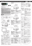
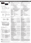
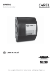
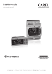
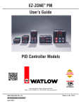
+050001511 - rel. 1.1 of 14/07/2009
ir33 smart - IR33S7HR0E Electronic controller for normal and high temperature static refrigeration units
bn1: normal temperature (2T10 °C) static refrigeration units
(no defrost)
Indications on the display
When flashing, the signals on the display indicate a request that cannot be implemented until the delay
timers have expired.
Temperature range: 2T10 °C
Temperature control
DIRECT MODE
NO POWER
& SIGNAL
CABLES
TOGETHER
1 2 3
N
Inputs
Outputs
L
NTC 1
R1: 16 A relay
Description
Set point
Control differential (hysteresis)
Minimum temperature alarm
Maximum temperature alarm
Temperature alarm delay
Default value
4 °C
2 °C
-30 °C
30 °C
30 min
(*) absolute alarm thresholds
READ CAREFULLY IN THE TEXT!
no alarm present
no malfunction
But- Pressing the button alone
ton
• if pressed for more than 5 s,
accesses the menu for setting the
type F parameters (frequent)
• in the event of alarms: mutes
the audible alarm (buzzer) and
deactivates the alarm relay
aux
aux
def
aux
Temperature range: 2T10 °C
Temperature control
IMPORTANT: separate the probe and digital input cables from the cables to
inductive loads and power cables to avoid electromagnetic disturbance.
Never run power cables (including electrical panel cables) and signal cables
in the same conduits.
def
def
if pressed for more than 5 s,
def
Set
activates /deactivates a manual
defrost
if pressed for more than 1 s,
DIRECT MODE
Set point
def
1 2 3
N
L
DI1/NTC3
56,5
65
DI2/NTC4
POWER
SUPPLY
PTC/NTC2
How to set the set point
PTC/NTC1
38,6
34,4
dima di foratura
drilling template
71x29 mm
R1
Step Action aux
aux
1
Press
for 2
secondsdef
2
Press
3
Press Set
6 7 8 9 10 11 12
L N
1
115/230 V~
50mA~ max ROOM PROBE
Set
aux
or
def
1
Inputs
Outputs
2
Room probe
Compressor
Name
St
rd
dl
dP1
AL (*)
AH (*)
Ad
Main parameters
(type F)
Wall mounting by two plastic brackets sliding in from side
Wiring diagram IR33S7HR0E
R1
EN60730-1
12 (2) A
UL 873 250 V~12A 5FLA
30LRA
- 10 T 6 0
1 2 3
R1
L
SERIAL board
& KEY
NTC 1
Type
Set point
Control differential (hysteresis)
Interval between defrosts
Max evaporator defrost duration
Minimum temperature alarm
Maximum temperature alarm
Temperature alarm delay
CtL
dEF
ALM
Default value
2 °C
2 °C
8 hours
30 min
-30 °C
30 °C
30 min
Press
3
def
Press Set
def
4
Press
Temperature range: 20T150 °C
Temperature control
Heater
6
Temp. °C
Set point
7
N
1
Inputs
Outputs
IROPZ48500:
Serial board interface RS485
L
DI1/NTC3
PTC/NTC2
R1: 16 A relay
Description
Set point
Control differential (hysteresis)
Minimum temperature alarm
Maximum temperature alarm
Temperature alarm delay
Default value
40 °C
2 °C
0 °C
150 °C
30 min
def
aux
Press Set
def
Setdef
ir33 SMART is loaded with 4 default configurations (sets of parameters). Each configuration identifies
a specific refrigeration application, and can be identified simply by the index (bn*) when switching the
instrument on.
Op. temp. range
Inputs
Relay output
2T10°C
NTC room
Compressor
2T10°C
NTC room
Compressor
bn3
Application
Normal temperature static refrigeration units
(no defrost)
Normal temperature static refrigeration
units with defrost (timed) by stopping the
compressor
High temperature thermostat
20T150°C
PTC room
Heater / Alarm
bn4
Standard CAREL (default configuration)
-50T90°C
Configurable Configurable
bn2
N
The user configuration selected in point 2 will
be loaded
Configurations
bn1
R1
Select the required configuration
(refer to the previous table)
This procedure can only be performed once: the most suitable configuration for the application, once
loaded, will remain active the next time the instrument is started.
When switching on the first time, bn0 corresponds to the Carel standard (default configuration). The
Set
procedure for
loading
Setone of the user configurations involves copying one of the sets of parameters
(bn1,...,bn4) to bn0. bn0 therefore always corresponds to the last configuration loaded.
Ind.
1 2 3
Main parameters
(type F)
Name
St
rd
rt
rH
rL
dl
dt1
dt2
dP1
dP2
dd
d8
d/1
d/2
AL
AH
Ad
Type
CtL
dEF
ALM
L
def
for 5
The display will scroll the list of type “F”
parameters (FREQUENT) (depends on Select the desired parameter
the configuration loaded)
The display will show the value of the
This is the current value of the
selected parameter
parameter
The value on the display will increase
or decrease
Set the desired value
The display will show the parameter
name again
IMPORTANT: parameters not yet
saved
The controller will display the temperatu- IMPORTANT: only now have all the
re read by the probes again
parameters been updated
2
Effect
2
Press
3
Press
aux
def
aux
aux
aux
&
or
def
def
Set
def
4
Press
5
Press Set
def
aux
aux
or
1
8
9
2
DI DI
Description
Set point
Control differential (hysteresis)
Temperature monitoring interval
Maximum temperature read
Minimum temperature read
Interval between defrosts
Evaporator end defrost temperature
AUX evaporator end defrost temp.
Maximum evaporator defrost duration
Maximum AUX evaporator defrost duration
Dripping time
Alarm bypass time after defrost and/or door open
Defrost probe 1 reading
Defrost probe 2 reading
Minimum temperature alarm
Maximum temperature alarm
Temperature alarm delay
aux
or
The value on the display will increase
or decrease
aux
The display will show the first parameter
The type “C” parameters also include
in the list (depends on the configuration
type “F”
loaded)
def
Default value
0 °C
2 °C
8 hours
4 °C
4 °C
30 min
30 min
2 min
1 hour
0 °C
0 °C
120 min
Enter the password “22”
The display will scroll the list of type “C”
Select the desired parameter
parameters (CONFIGURATION)
aux
The display will show the value of the
selected parameter
This is the current value of the
parameter
Set
The value on the display will increase
or decrease
Set the desired value
The display will show the parameter
name again
IMPORTANT: parameters not yet
saved
def
Press Set
Set
Repeat steps 4, 5,
6&
Set
7 for all parameters
required
Press Set
seconds
Meaning
for After 5 seconds the display will show “0” Access to type “C” parameters
requires the password
def
Set
Set
Set
Press
Set
aux
def
6 7 8 9 10 11 12
L N
1
115/230 V~
50 mA~ max
Press Set
seconds
Press Set
5 seconds
7
DI2/NTC4
DI1/NTC3
Meaning
‘bn0’ is the current configuration.
(Standard Carel when first switched on or other
user configuration, if loaded)
Set
Set
Press Set
Set
def
Repeat steps
2, 3,
4&
Set
5 for all parameters
required
1
6
Connection diagram
PTC/NTC2
Effect
After 2 seconds
the display shows the
message ‘bn0’
The display shows the
messages ‘bn1’, ‘bn2’,
‘bn3’, ‘bn4’
The display shows “Std”
for 1 sec
or
def
bn4: standard CAREL (default configuration)
PTC/NTC1
Step Action aux
Switch the instrument
on
aux
1
while holding
def
aux
Step Action
PTC 1
POWER
SUPPLY
aux
def
After 5 seconds the display will show the Access to type “F” parameters is
first parameter, “St” (set point)
direct
How to access and
set type “C” parameters (CONFIGURATION, password
def
def
protected)
L N
1
115/230 V~
50mA~ max ROOM PROBE
How to select and load a user configuration
or
Meaning
aux
(*) absolute alarm thresholds
IROPZKEY**:
Programming key
The set point is modified and saved
aux
6 7 8 9 10 11 12
Room probe
Heater/Alarm
Name
Type
St
CtL
rd
AL (*)
AH (*)
ALM
Ad
Main parameters
(type F)
PTC/NTC1
Connection diagram
R1
aux
aux
aux
def
5
1 2 3
Set the desired value
Effect
aux
2
L N
1 2 1 2
115/230 V~
50mA~ max PROBES DI DI
IROPZDSP00:
Display interface option
Step Action
bn3: high temperature (20T150 °C) thermostat (reverse mode)
POWER
SUPPLY
This the currently active control set point
Set
Press
for 5aux
secondsdef
rd
Meaning
How to access and set type “F” parameters (FREQUENT, not protected by
password)
1
REVERSE MODE
2
Set
(*) absolute alarm thresholds
6 7 8 9 10 11 12
Optional connections
def
Effect
After 2 seconds the
display shows the current
set point
The value on the display
will increase or decrease
The controller will display
the temperature read by
the probes again
Another way of changing the set point is to set parameter “St” (see the tables below)
R1: 16 A relay
Description
DI2/NTC4
N
3
• if pressed for more than 5 s together with PRG/MUTE, accesses the menu
Temp. °C
rd
Connection diagram
Wall mounting ir33
or
• if pressed with SET for
Start-up: if pressed
Automatic address assimore than 5 s, accesses
for more than 5 s at gnment: if pressed for
the menu for setting type C start-up activates the more than 1 s enters
parameters (configuration) procedure for setting the automatic serial
or downloading parameters the default parameters address assignment
• if pressed for more than
procedure
5 s with UP/AUX resets any
alarms with manual reset
• if pressed for more than 5 s together with DOWN/DEF, activates/deactivates
the continuous cycle
• if pressed for more than 5 s together with SET starts the report printing
procedure (function available but to be implemented)
• if pressed for more than 5 s together with PRG/MUTE, resets any alarms
with manual reset
if pressed for more than 5 s together with UP/AUX activates/deactivates the
continuous cycle
aux
80,6
aux
Pressing together with other buttons
re (function available but to be implemented)
70,5
79
76,2
Press
function not activated
Set displays and/or sets the set point for setting the type C parameters (configuration) or downloading the
Set
parameters
• if pressed for more than 5 s with UP/AUX starts the report printing proceduSet
Dimensions (mm)
2
function activated
aux
bn2: normal temperature (2T10 °C) static refrigeration units with defrost (timed) by stopping the compressor
Compressor
NO POWER
& SIGNAL
CABLES
TOGETHER
ALARM
defrost call
alarms in norm. operation
(e.g. high/low temp.) or immediate or delayed external
alarm from digital input
malfunction(e.g. EEPROM
error or faulty probes)
function called
Buttons on the keypad
L N
1
115/230 V~
50mA~ max ROOM PROBE
Room probe
Compressor
Name
Type
St
CtL
rd
AL (*)
AH (*)
ALM
Ad
Main parameters
(type F)
DI1/NTC3
6 7 8 9 10 11 12
R1
With reference to the label on the rear of the instrument and the required application
1. Check that power supply, probes and loads (compressor, heaters, etc.) are suitable for the
instrument.
2. Fasten the instrument to the panel as shown in the following figure.
3. Make all the required electrical connections.
4. Power up the unit.
5. After around 2 seconds, if the instrument displays the temperature read by the probes connected
to the device, go directly to point 7. If nothing is displayed or an alarm is signalled (alarm codes on
the display), power down, check the connections and the power supply and go to point 6.
6. Power the unit up again. If the instrument now correctly displays the temperature, go to point 7. If,
on the other hand, the problem described in point 5 is repeated, see the table “Alarms and signals:
display, buzzer and relay” to identify the cause of the problem.
7. ir33 smart is now ready to be configured. For correct configuration based on the required
application, see the section “How to select and load a configuration”.
no defrost call
delayed external alarm
(before the time “A7“has
elapsed)
Flashing
compress. call
DI2/NTC4
POWER
SUPPLY
READ ME NOW!!!
defrost in progress
CONT. CYCLE
PTC/NTC2
115/230 Vac switching power supply
16 A compressor relay
Management of NTC (-50 to +90°C) and PTC (-50 to +150°C) sensors
Simple and intuitive installation and configuration
4 pre-loaded configurations for the most common refrigeration applications
DEFROST
SERVICE
Connection diagram
PTC/NTC1
•
•
•
•
•
Normal operation
OFF
compress. off
Temp. °C
rd
Set point
READ CAREFULLY IN THE TEXT!
• Electronic controller for normal and high temperature static refrigeration units
COMPRESS.
ON
compressor on
Icon Function
Compressor
for 5
The controller will display the temperatu- IMPORTANT: only now have all the
re read by the probes again
parameters been updated
For both types of access (type “F” and type “C”) there is a timeout (no button on the keypad pressed for
aux
1 min), the procedure is ended without saving the parameters.
def
Accessing the parameters divided by functional blocks (allows the user to
scroll the list of parameters in blocks)
Once having Set
accessed the type “F” or “C” parameters (see tables above)
Step Action
1
Press
2
Press
3
Press
aux
aux
aux
def
def
aux
Set
Set
def
Set
or
def
Set
Effect
The display will show the
name of the functional
block that the parameter
belongs to
The display will show
the name of the other
functional blocks
The display will show the
name of the first parameter in the functional block
selected
Meaning
Example “CMP” for the compressor parameters,
“dEF” for the defrost parameters
Example “dEF” for the defrost parameters
Example “dl” for “dEF”
Technical specifications
Operating parameters
Voltage
Power
Power supply
115-230 V~, 50/60 Hz
6 VA, 50 mA ~ max.
Insulation guaran- insulation from very low
reinforced 6 mm in air, 8 mm on surface, 3750 V insulation
teed by the power voltage parts
insulation from relay
basic 3 mm in air, 4 mm on surface, 1250 V insulation
supply
outputs
Inputs
S1 (probe 1)
NTC & PTC
S2 (probe 2)
NTC & PTC
DI1
voltage-free contact, contact resistance <10 Ohm, closing current 6 mA
S3
NTC or NTC & PTC
Maximum distance of probes and digital inputs less than 10 m
Note: in the installation keep power supply and load connections separate from probe, digital
input, repeater display and supervisor cables.
Type of probe
Std. CAREL NTC
10 kOhm at 25 °C, range -50T90 °C
meas. error
1 °C in range -50T50 °C
3 °C in range 50T90 °C
High temperature NTC
50 kOhm at 25 °C, range -40T150 °C
meas. error
1.5 °C in range -20T115 °C
4 °C in range outside of -20T115 °C
Std. CAREL PTC
985 Ohm at 25 °C, range -50T150 °C
meas. error
2 °C in range -50T50 °C
4 °C in range 50T150 °C
Relay outputs
EN60730-1
UL873
relay
250 V~
operating cycles
250 V~
operating cycles
R1 (*)
12 (2) A
100,000
12 A resistive 5 FLA
30,000
N.O./N.C.
30 LRA C300
insulation from very low voltage parts
reinforced: 6 mm in air, 8 mm on surface,
3750 V insulation
insulation between independent relay outputs
basic: 3 mm in air, 4 mm on surface,
1250 V insulation
(*) Relays not suitable for fluorescent loads (neon lights, etc.) that use starters (ballasts) with phase shifting capacitors.
Fluorescent lamps with electronic controllers or without phase shifting capacitors can be used, depending on the operating limits specified for each type of relay.
Connections
screw terminals for cables from 0.5 to 2.5 mm2 max current 12 A
The correct sizing of the power and connection cables between the instrument and the loads is the installer’s responsibility. In max. load and max. operating temp. conditions, the cables used must be suitable for operation at least up to 105 °C.
Case
plastic 34.4 x 76.2 x 79 mm (mounting depth 70,5 mm)
Assembly
smooth, hard and indeformable panel using side fastening brackets to press in fully
drilling template
28.8±0.2 x 76.2±0.2 mm
Display
digits
3 digit LED
display
from -99 to 999
operating status
indicated by graphic icons on the display
Keypad
4 silicone rubber buttons
Infrared receiver
available
Buzzer
available
Operating temperature
-10T60 °C
Operating humidity
<90% rH non-condensing
Storage temperature
-20T70 °C
Storage humidity
<90% rH non-condensing
Front panel index of protection
assembly on smooth and indeformable panel
with IP65 gasket
Environmental pollution
2 (normal situation)
PTI of insulating materials
printed circuits 250, plastic and insulating
materials 175
Period of electrical stress across the insulating parts
long
Category of resistance to heat and fire
category D and category B (UL 94-V0)
Class of protection against voltage surges
category 1I
Type of action/disconnection
1B relay contacts (microswitching)
Construction of the control device
built-in, electronic
Classification according to protection against electric shock
Class 2 when appropriately integrated
Device designed to he hand-held or integrated into equipment
no
designed to be hand-held
Software class and structure
class A
Cleaning the front panel of the instrument
only use neutral detergents and water
Serial interface for CAREL network
external
Maximum distance between interface and display
10 m
Programming key
available
Complete list of parameters for each configuration
frequent parameters ‘F’
psw protected parameters ‘P’
Cd. Parameter
/2
/3
/4
/5
/6
/tl
Pro
/P
/A2
/A3
/c1
/c2
/c3
St
rd
r1
r2
ctl r3
r4
r5
rt
rH
rL
c0
c1
c2
cmp c3
The IR33 range fitted with the standard CAREL NTC sensor is compliant with standard EN 13485 on thermometers
for measuring the air and product temperature for the transport, storage and distribution of chilled, frozen, deepfrozen/quick-frozen food and ice cream. Designation of the instrument: EN13485, air, S, A, 1, -50T90°C. The standard
CAREL NTC sensor is identifiable by the printed laser code on “WP” models, or the code “103AT-11” on “HP”
models, both visible on the sensor part.
Safety standards: compliant with the relevant European standards.
Installation warnings:
dP2
Reset alarms with manual reset
The alarms with manual reset can be reset by pressing “
”&“
aux
” for more than 5 s.
” for 5 s.
d/1
d/2
aux
def
dC
Set
Continuous cycle
d8
d9
def
As well as automatic defrost, a manual defrost can be activated, if the temperature conditions are right, by
def
Defrost on start-up
Defrost delay on start-up or
multifunction input
d8d
aux
aux
d4
dd
dEF
def
To activate Set
the continuous cycle function press“ aux ” & “
” for more than 5 s. During operation in continuous
cycle, the compressor will continue running and will stopSet
at the timeout of the cycle or when reaching the minimum
temperature (AL = minimum temperature alarmdef
threshold).
Set
Continuous cycle setting: parameter ‘cc’ (continuous cycle duration):
‘cc’= 0 never active; parameter ‘c6’ (alarm bypass
after continuous cycle): excludes or delays the low temperature alarm at the end of the continuous cycle.
Maximum interval between
consecutive defrosts
Evaporator end defrost
temperature
AUX evaporator end defrost
temperature
Maximum evaporator defrost
duration
Maximum AUX evaporator
defrost duration
Defrost activation delay
d6
ir33 smart comes with a three digit LED display for the temperature and icons to indicate operating status. It can also
be connected, via a special interface, to a further display, used for example to read the third probe.
Type of defrost
d3
d5
Display
pressing “
c6
Low temp. alarm bypass time
after continuous cycle
dP1
IRTRRES000 small infrared remote control
IROPZKEY00 parameter programming key, extended memory with 12 V batteries
IROPZ485S0 RS485 serial card with automatic polarity recognition (+/-)
PSOPZPRG00 programming key kit
PSOPZKEY00 parameter programming key with 12 V batteries
PSOPZKEYA0 parameter programming key, extended memory, with external 230 Vac power supply
Manual defrost
Running time in continuous
cycle
dt2
Option codes
Maximum temperature
acquired in the session
Minimum temperature
acquired in the session
Fan start delay (if relay fitted)
on power-up
Minimum time between
consecutive starts of the
compressor
Minimum compressor off time
Minimum compressor on time
cc
dt1
• the connection cables must guarantee insulation up to 90 °C; and, if necessary, up to 105 °C
• adequately secure the connection cables to the outputs so as to avoid contact with very low voltage components.
1 to 15
Temperature display refresh speed (0 to 15)
Weight % of temp. control probe 2 (0 to
Virtual probe
100%)
Select °C or °F
0: °C, 1: °F
Decimal point
0: enabled, 1: disabled
Probe reading displayed
1: virtual probe
2: probe 1
3: probe 2
Reading on remote display
4: probe 3
5: probe 4
6: probe 5
7: set point
0: NTC –50T90 °C
Select type of probe
1: NTC –40T150 °C
2: PTC –50T150 °C
0: no probe
1: product probe
Probe 2 configuration
2: defrost probe
3: condenser probe
4: antifreeze probe
Probe 3 configuration
As for probe 2
Probe 1 calibration or offset Correction to reading of probe 1 (-20T20 °C)
Probe 2 calibration or offset Correction to reading of probe 2 (-20T20 °C)
Probe 3 calibration or offset Correction to reading of probe 3 (-20T20 °C)
Set point
r1Tr2 °C
Value of the temperature control differential
Control delta
or hysteresis (0.1T20 °C)
Minimum value settable for the set point
Minimum set point
(-50Tr2 °C)
Maximum value settable for the set point
Maximum set point
(r1T200 °C)
0: direct thermostat with defrost control
(cool)
Operating mode
1: direct thermostat (cool)
2: reverse thermostat (heat)
Automatic night-time set point Value added to the set point in night-time
variation
operation (see ‘A4’) (-20T20 °C)
Temperature monitoring
0: monitoring disabled
probe
1: monitoring enabled
Temperature monitoring
temperature recording hours (0 to 999)
interval
Duty setting or safety relay
dI
d10
d11
d12 Advanced defrosts
dn Nominal defrost duration
Proportional factor for
variation in ‘dl’
A0 Alarm and fan differential
Alarm thresholds (AL, AH)
A1 relative to the set point (St)
or absolute
AL Low temp. alarm threshold
AH High temp. alarm threshold
Delay time for high and low
Ad
temperature alarms
2: Press the button
on the instrument connected to the network, the instrument recognises the message sent by
the remote application, automatically setting the address to the required value and sending a confirmation message
to the application, containing the unit code and firmware revision (message ‘V’). When the message sent by the
aux
remote application is recognised, the instrument displays the message ‘Add’ for 1 second, followed by the value of
the serial address assigned;
3: The application, ondefreceiving the confirmation message from the units connected to the network, saves the
information received in its database, increases the serial address and resumes sending the message ‘<!ADR>‘.
4: The procedure can be repeated starting from point 2 on another unit connected to the network, until all network
addresses are defined.
Set
dH
Note: when the operation for assigning an address to an instrument has finished, for reasons of safety, the
operation is inhibited for 1 minute on that instrument. Consequently, a different address cannot be re-assigned to
the instrument during that time.
ALM
A4
A6
A7
A8
Ac
CAREL INDUSTRIES HQs.
Via dell’Industria, 11 - 35020 Brugine - Padova (Italy)
Tel. (+39) 0499716611 – Fax (+39) 0499716600
http://www.carel.com – e-mail: [email protected]
AE
Configuration
bn1 bn2 bn3 bn4
4
4
4
4
0
0
0
0
0
0
0
0
0
0
0
0
0
0
0
0
Acd
ALM
AF
2
2
2
1
0
0
2
0
0
0
0
0
0
0
0
0
4
0
0
0
0
2
0
0
0
0
40
0
0
0
0
0
2
2
2
2
0
-50
ALF
AdF
H0
H2
-30 -30
30
30
1
0
3.0
3.0
0
0
0
0
-
-
-
-
-
-
-
-
-
-
-
-
0 to 15 min
0
0
0
0
0 to 15 min
0
0
0
0
0 to 15 min
0 to 15 min
Compressor operating time in the event of
control probe fault (fixed off time 15 min)
(0 to 100 min)
Compressor operating time even when the
temperature is below the set point (0 to
15 hours)
0
0
0
0
0
0
0
0
15
15
0
0
0
0
0
0
0 to 250 hours
2
2
2
2
0: heater by temperature; 1: hot gas by
temperature; 2: heater by time; 3: hot gas
by time; 4: heater by time with temperature
control
0
2
0
0
0 to 250 hours
8
8
8
8
H3
H4
CmF
150 60
2
H6
0
3.0 3.0
H8
H9
Hdh
Code
Description
Virtual control probe fault
Room probe S1 fault
Defrost probe S2 fault
Probe S3 fault
Probe not enabled
low temperature alarm
high temperature alarm
immediate alarm from external contact
delayed alarm from external contact
defrost running
defrost on evaporator 1 ended by timeout
defrost on evaporator 2 ended by timeout
maximum pump down time alarm
low pressure alarm
autostart in pump down
high condenser temperature pre-alarm
high condenser temperature alarm
Unit parameter EEPROM error
Operating parameter EEPROM error
Connection with IR remote control active
Automatic address assignment procedure in progress
Report printing in progress
Low relative humidity procedure activation
High relative humidity procedure activation
Start continuous cycle call
End continuous cycle call
Start defrost call
End defrost call
Switched ON
Switched OFF
Reset alarms with MAN reset, reset temperature
monitoring
Alarm on unit 1-6 in the network
Download procedure in progress
Download procedure with errors on unit 1-6
0
0
0
0
0
0
0
0
1
1
1
0
2
2
1
1
1
0
0
0
0
0
0
rES
n1-n6
dnL
d1-d6
4
4
4
4
4
4
4
1 to 250 min
30
30
30
30
1 to 250 min
30
30
30
30
0
0
0
0
-
-
-
0
0
0
0
0
0
1
1
1
0
0
0
(-20T20 °C)
0: skip defrost and automatic variation in
dl disabled
1: skip defrost disabled and automatic
variation in dl enabled
2: skip defrost enabled and automatic
variation in dl disabled
3: skip defrost and automatic variation in
dl enabled
1 to 100%
65
65
65
65
0 to 100%
50
50
50
50
0.1T20 °C
2.0
2.0
2.0 2.0
1
1
0: relative; 1: absolute
0
1
10
10
0
0
0
0
0
0
0
0
-5
1
1
-5
1
1
-5
1
1
-5
1
1
1
1
1
1
0
0
0
0
0
0
0
0
0
0
0
0
0
0
0
0
0
0
0
0
0
0
0
0
Icon flashing
-
Buzzer
ON
OFF
OFF
OFF
OFF
ON
ON
ON
ON
OFF
OFF
OFF
ON
ON
ON
OFF
ON
OFF
OFF
-
AUTO
AUTO
AUTO
AUTO
AUTO
AUTO
AUTO
AUTO
AUTO
AUTO
AUTO
AUTO
AUTO/MAN
AUTO/MAN
AUTO/MAN
AUTO/MAN
MAN
AUTO
AUTO
-
-
-
-
-
always on
-
-
-
Reset
-
-
ON
AUTO
-
OFF
Note:the buzzer is activated if enabled by parameter ‘H4’. It can be disabled from the CAREL supervisory system.
Manual reset on pressing PRG/MUTE
0
-50T200 °C
-50T200 °C
-30 -30 0
+30 +30 150
0 to 250 min
30
30
30 120
0
0
0
0
0
0
0
0
0
0
0
0
0
0
0
0
70
70
70
70
0: input not active
1: immediate external alarm
2: delayed external alarm (delay time A7)
3: enable defrost
4: start defrost from external contact
5: door switch with compressor and evaporator fans OFF
6: remote on/off
7: curtain switch
Function of digital input DI1
8: low pressure switch input for pump down
9: door switch with fans OFF only
0: direct/reverse operation
11: light sensor
12: AUX output activation
13: door switch with compressor and fans
OFF (light not managed)
14: door switch with fans OFF (light not
managed)
Stop compressor from external forced compressor operating time in the
alarm
event of external alarms (0 to 100 min)
Delay time for delayed
If ‘A4’= 2 (0 to 250 min)
external alarm
0: signal ‘Ed1’ and ‘Ed2’ on the display (end
defrost due to maximum duration dP1/dP2)
Enable alarms Ed1 and Ed2
disabled
1: signal ‘Ed1’ and ‘Ed2’ enabled
High condenser temperature 0T200 °C
alarm
10
Below is a table that describes the alarms and control signals, with the corresponding description, status
of the buzzer, alarm relay and type of reset.
0 to 250 min
4
10
Alarms and signals: display, buzzer and relay
interval between defrost call and effective
activation of the relay
0: disabled; 1: enabled
-50T200 °C
-50T200 °C
Differential or hysteresis for the activation/
High condenser temperature
deactivation of the high condenser temperaalarm differential
ture pre-alarm (0.1T20 °C)
High condenser temperature
0 to 250 min
alarm delay
0: sensor in the door jamb (the inside light
is switched on when the sensor detects light
and off when it detects darkness)
>0: internal sensor (the inside light is
switched on when the sensor detects
Off time with light sensor
light. After the time AF in seconds the light
is switched off for 3 sec. In the event of
darkness the inside light remains off, while in
the event of light it is switched on again and
a cycle starts with a minimum time of 3 sec.
(0 to 250 sec.)
Antifreeze alarm threshold
Active if ‘/A2’ or ‘/A3’= 4 (-50T200 °C)
Antifreeze alarm delay
0 to 15 min
Serial address
0 to 207
0: setting of type F parameters and set point
disabled
1: all settings are possible
2: setting of type F parameters, settings from
remote control and set point disabled
Lock keypad and/or remote 3: settings from remote control disabled
control
4: continuous cycle, defrost, setting of type F
parameters and ON/OFF disabled
5: continuous cycle, defrost, setting of type F
parameters, set point and ON/OFF disabled
6: continuous cycle, defrost, setting of type F
parameters and set point disabled
Remote control enable code 0 to 255
Terminal buzzer
0: enabled; 1: disabled
1 (bit 0): enable/disable print report
2 (bit 1): enable/disable defrost
4 (bit 2): enable/disable continuous cycle
Terminal keypad lock
8 (bit 3): enable/disable mute
configuration
16 (bit 4): not associated
32 (bit 5): not associated
64 (bit 6): enable/disable ON/OFF
0: time band linked to the light output
Select output activated by
1: time band linked to the AUX output (see
time band
‘H1’ or ‘H5’)
Enable set point variation with 0: set point variation with time band disabled
time bands
1: set point variation with time band enabled
AUX output configured as light or AUX
(‘H1’= 2, 3, 8 or 9) remains deactivated
until the control temperature is less than
Anti-sweat heater offset
‘St’+’Hd’ when switching the instrument on
for the first time or when resetting alarms.
(-0T200 °C)
IMPORTANT WARNING: for the set times to become immediately operational, the instrument needs to be
turned off and on again. If this operation is not carried out, timing resumes operation the next time it is used,
when the internal timers are reset.
rE
E0
E1
E2
“___”
LO
HI
IA
dA
dEF
Ed1
Ed2
Pd
LP
AtS
cht
CHT
EE
EF
rct
Add
Prt
LrH
HrH
ccb
ccE
dFb
dFE
On
OFF
0: temperature alternating with ‘dEF’
1: display frozen on last temperature before
Display during defrost
1
defrost
2: ‘dEF’
Waiting time before reactivating compressor
Dripping time after defrosting
2
and fans at the end of a defrost (0 to 15 min)
Alarm bypass time after defrost
See ‘A4’ (0 to 250 hours)
1
and/or door open
Door open alarm delay
See ‘A4’ (0 to 250 hours)
0
0: protection times respected; 1: protection
Defrost priority over comprestimes not respected; the defrost has higher
0
sor protection times
priority.
Display defrost probe 1
Display defrost probe 2
0: ‘dI’ in hours, ‘dP1’ and ‘dP2’ in minutes
Time base for defrost
0
1: ‘dI’ in minutes ,‘dP1’and ‘dP2’ in seconds
Compressor operating time with evaporator
Defrost time in “Running
temperature less than ‘d11’, after which a
0
time” mode
defrost is called (0 to 250 hours)
Evaporation temperature below which the
Defrost temperature threshold compressor must continue operating for
1
in “Running time” mode
the time ‘d10’ to generate a defrost call
Set
Automatic serial address assignment
This is a special procedure that, by using an application installed on a PC, sets and manages the addresses of all the
instruments (that include this feature) connected to the CAREL network in a simple way.
The procedure is very simple:
1: Using the remote application, start the “Network definition” procedure; the application begins to send a special
message (‘<!ADR>’) across the CAREL network, containing the network address;
Description
Measurement stability
Probe display response
c4
d0
masked parameters (hidden)
0
0
Disposal of the product
The appliance (or the product) must be disposed of separately in compliance with the local standards in force on waste
disposal
IMPORTANT WARNINGS:The CAREL product is a state-of-the-art device, whose operation is specified in the technical
documentation supplied with the product or can be downloaded, even prior to purchase, from the website www.carel.
com. The customer (manufacturer, developer or installer of the final equipment) accepts all liability and risk relating to the
configuration of the product in order to reach the expected results in relation to the specific final installation and/or equipment. The
failure to complete such phase, which is required/indicated in the user manual, may cause the final product to malfunction; CAREL
accepts no liability in such cases. The customer must use the product only in the manner described in the documentation relating
to the product.The liability of CAREL in relation to its products is specified in the CAREL general contract conditions, available on the
website www.carel.com and/or by specific agreements with customers.
+050001511 - rel. 1.1 of 14/07/2009