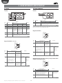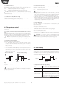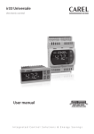
1
easy / easy compact / easy split
electronic digital thermostats with defrost control
User manual
NO POWER
& SIGNAL
CABLES
TOGETHER
READ CAREFULLY IN THE TEXT!
Integrated Control Solutions & Energy Savings
ENG
WARNINGS
WARNINGS
NO POWER
& SIGNAL
CABLES
TOGETHER
READ CAREFULLY IN THE TEXT!
CAREL bases the development of its products on decades of experience
in HVAC, on the continuous investments in technological innovations
to products, procedures and strict quality processes with in-circuit and
functional testing on 100% of its products, and on the most innovative
production technology available on the market. CAREL and its subsidiaries
nonetheless cannot guarantee that all the aspects of the product and the
software included with the product respond to the requirements of the final
application, despite the product being developed according to start-of-theart techniques. The customer (manufacturer, developer or installer of the final
equipment) accepts all liability and risk relating to the configuration of the
product in order to reach the expected results in relation to the specific final
installation and/or equipment. CAREL may, based on specific agreements, acts
as a consultant for the positive commissioning of the final unit/application,
however in no case does it accept liability for the correct operation of the final
equipment/system.
The CAREL product is a state-of-the-art device, whose operation is specified
in the technical documentation supplied with the product or can be
downloaded, even prior to purchase, from the website www.carel.com.
Each CAREL product, in relation to its advanced level of technology, requires
setup/configuration/programming/commissioning to be able to operate in
the best possible way for the specific application. The failure to complete such
operations, which are required/indicated in the user manual, may cause the
final product to malfunction; CAREL accepts no liability in such cases.
Only qualified personnel may install or carry out technical service on the
product.
The customer must only use the product in the manner described in the
documentation relating to the product.
In addition to observing any further warnings described in this manual, the
following warnings must be heeded for all CAREL products
• prevent the electronic circuits from getting wet. Rain, humidity and all
types of liquids or condensate contain corrosive minerals that may damage
the electronic circuits. In any case, the product should be used or stored
in environments that comply with the temperature and humidity limits
specified in the manual.
• do not install the device in particularly hot environments. Too high
temperatures may reduce the life of electronic devices, damage them and
deform or melt the plastic parts. In any case, the product should be used
or stored in environments that comply with the temperature and humidity
limits specified in the manual.
• do not attempt to open the device in any way other than described in the
manual.
• do not drop, hit or shake the device, as the internal circuits and mechanisms
may be irreparably damaged.
• do not use corrosive chemicals, solvents or aggressive detergents to clean
the device.
• do not use the product for applications other than those specified in the
technical manual.
Separate as much as possible the probe and digital input signal cables from
the cables carrying inductive loads and power cables to avoid possible
electromagnetic disturbance.
Never run power cables (including the electrical panel wiring) and signal
cables in the same conduits.
DISPOSAL
The product is made up of metal parts and plastic parts.
In reference to European Union directive 2002/96/EC issued on 27 January
2003 and the related national legislation, please note that::
1. WEEE cannot be disposed of as municipal waste and such waste must be
collected and disposed of separately;
2. the public or private waste collection systems defined by local legislation
must be used. In addition, the equipment can be returned to the distributor
at the end of its working life when buying new equipment;
3. the equipment may contain hazardous substances: the improper use or
incorrect disposal of such may have negative effects on human health and
on the environment;
4. the symbol (crossed-out wheeled bin) shown on the product or on the
packaging and on the instruction sheet indicates that the equipment has
been introduced onto the market after 13 August 2005 and that it must
be disposed of separately;
5. in the event of illegal disposal of electrical and electronic waste, the
penalties are specified by local waste disposal legislation.
All of the above suggestions likewise apply to the controllers, serial boards,
programming keys or any other accessory in the CAREL product portfolio.
CAREL adopts a policy of continual development. Consequently, CAREL
reserves the right to make changes and improvements to any product
described in this document without prior warning.
The technical specifications shown in the manual may be changed without
prior warning.
The liability of CAREL in relation to its products is specified in the CAREL general
contract conditions, available on the website www.carel.com and/or by
specific agreements with customers; specifically, to the extent where allowed
by applicable legislation, in no case will CAREL, its employees or subsidiaries
be liable for any lost earnings or sales, losses of data and information, costs of
replacement goods or services, damage to things or people, downtime or any
direct, indirect, incidental, actual, punitive, exemplary, special or consequential
damage of any kind whatsoever, whether contractual, extra-contractual or
due to negligence, or any other liabilities deriving from the installation, use or
impossibility to use the product, even if CAREL or its subsidiaries are warned
of the possibility of such damage.
3
easy/easy compact/easy split +030220791 - rel. 3.1 - 25.01.2010
ENG
Content
1. INTRODUCTION
7
1.1 Main characteristics ............................................................................................7
1.2 Models .......................................................................................................................7
1.3 Main differences between easy, easy compact and easy split ......9
1.4 NTC and PTC probes .........................................................................................9
1.5 Accessories..............................................................................................................9
1.6 Definitions ...............................................................................................................9
2. ASSEMBLY AND INSTALLATION
10
2.1 Assembly ...............................................................................................................10
2.2 Electrical connections ....................................................................................11
2.3 Wiring diagram for multiple units ........................................................13
3. USER INTERFACE AND START UP
14
3.1 easy ............................................................................................................................14
3.2 easy compact ......................................................................................................14
3.3 easy split .................................................................................................................15
3.4 Preliminary configurations ..........................................................................15
3.5 Functions available from the keypad....................................................15
4. FUNCTIONS AND PARAMETERS
17
4.1 Temperature probe settings .......................................................................17
4.2 Temperature display.......................................................................................17
4.3 Temperature control ......................................................................................18
4.4 Duty Setting ........................................................................................................18
4.5 Continuous cycle ...........................................................................................19
4.6 Compressor protection .................................................................................19
4.7 Defrost ....................................................................................................................20
4.8 Alarm parameters ............................................................................................22
4.9 Door open/closed management...........................................................25
4.10 Evaporator fan management parameters .....................................27
4.11 Clock and time band parameters.........................................................28
4.12 Rapid parameter set selection (EZY) .................................................29
4.13 Other settings ..............................................................................................29
5. TABLES OF ALARMS AND PARAMETERS
31
5.1 Table of alarms and signals ........................................................................31
5.2 Description of the main signals and alarms .....................................31
5.3 Data error ...............................................................................................................32
5.4 Modifying the parameters..........................................................................32
5.5 Setting the default parameters ...............................................................32
5.6 Table of easy parameters .............................................................................33
5.7 Table of easy compact parameters .......................................................34
5.8 Table of easy split parameters ..................................................................35
5.9 Table of EZY parameter sets ......................................................................36
5.10 Troubleshooting.............................................................................................38
6. TECHNICAL SPECIFICATIONS
39
6.1 easy technical specifications ....................................................................39
6.2 easy compact technical specifications...............................................39
6.3 easy split technical specifications ..........................................................40
6.4 Electromagnetic compatibility ................................................................41
5
easy/easy compact/easy split +030220791 - rel. 3.1 - 25.01.2010
ENG
1. INTRODUCTION
easy, easy compact and easy split are electronic microprocessor
controllers with LED display, developed for the management of
refrigerating units, display cabinets and showcases. They exploit the
experience and the success of the previous PJ32 range, with the objective
of offering a product that is simpler and more economical. The structure
of the parameters has been enhanced with new functions for more
dynamic and effective management of the temperature control and
defrost.
easy compact the smallest, most economical easy model, with one relay
only, and a simplified display.
easy split model with separate terminal and power board.
1.1 Main characteristics
The following table lists the main features of the easy, easy compact and
easy split controllers.
Features
Ergonomic polycarbonate keypad with three buttons
Keypad protection to prevent tampering
Access to the configuration parameters by password
Digit display
Decimal point
Display in °C or °F
LED display
Defrost (*)
- by stopping the compressor
- heater
- hot gas
- heater with temperature control
Duty setting function
Continuous cycle function
Relay outputs (*)
Up to two analogue inputs for NTC or PTC probes (*)
Up to two analogue inputs for NTC/NTC-HT probes
Multifunction analogue or digital input (*)
In the models with at least 2 probes: display second/third probe (*)
Input for CAREL IROPZKEY** programming key (*)
Input for external CAREL IROPZ485 connector (RS485 network) (*)
Buzzer (audible alarm signals) (*)
Fixed or removable terminals
Fastening from rear or front
Easy Set (rapid instrument configuration selection)
easy
3
3
3
-199…999
3
3
Models
easy compact
3
3
3
-99...99
3
3
easy split
3
3
3
-199…999
3
3
3
3
3
3
3
3
3
3
3
3
3
3
3
3
3
3
3
3
3
3
3
3
3
3
3
3
3
3
3
3
3
3
3
3
3
3
3
3
3
Table 1.a
(*) Check that this is available on the model in question.
Important: each of the features should be checked for the model
in question.
1.2 Models
The easy and easy compact controllers differ as regards operation, and
the number inputs and outputs. easy split models feature a separate
terminal and power board.
easy models:
PJEZS (0, 1, 6, 7)*; PJEZ(X, Y)*; PJEZC* controllers and PJEZM(0, 1, 6, 7)*
thermometer only
easy compact models:
PJEZS(N, P)* controller and PJEZM(N,P)* thermometer only
easy split models:
PJEZ*8**** controllers with one relay used for the light output.
Models and features
S models (PJEZS*)
The ideal solution for the management of static refrigeration units (that is,
without fan on the evaporator), operating at normal temperature (above 0
°C). This model, in fact, performs the functions of thermometer, displaying
the temperature of the unit, and electronic thermostat, activating the
compressor (or the solenoid valve in the case of multiplexed units) so as
to maintain the required temperature. In addition, it features compressor
protection algorithms and automatic defrost function by shutting down
the compressor.
7
easy/easy compact/easy split +030220791 - rel. 3.1 - 25.01.2010
ENG
X and Y models (PJEZX*, PJEZY*)
These are designed for the management of static units operating at
low temperature (that is, below 0ºC), which require active defrost using
electric heaters or the injection of hot gas. The PJEZ(Y,X)*, in fact, as well
as working as a thermometer and a thermostat (like the PJEZS), also
manages the defrost actuator. The frequency and duration of the defrost
can be set. The end defrost can occur according to the temperature
reached (connecting a probe to the evaporator) or by time. In addition
these models feature two probe inputs, for the control probe (room), the
defrost probe, and a digital input (this can also be configured as a probe).
There are two outputs, for controlling the actuator (compressor ) and the
. Models PJEZY and PJEZX differ in that:
defrost
• PJEZY has relays that are electrically connected together;
• PJEZX has independent relays.
C models (PJEZC*)
The most complete solution for low temperature ventilated units, with
three relays for complete control of the compressor, fan and defrost
functions. The three relays are included in the very compact case in the
versions with 230 V or 115 V power transformer, without compromising
the performance or reliability of the product.
M models (PJEZM*)
Solution for simply measuring the temperature.
Summary table of the functions associated with the models
function
temperature display
temperature measurement in °C/°F
parameter access using password
set point modification
night-time set point management
enable/disable direct probe 2 alarm
temperature probe calibration
temperature control in DIRECT mode
temperature control in REVERSE mode
compressor protectors
duty setting
continuous cycle
defrost
high/low temperature alarm
dirty condenser alarm
evaporator fan management
ON/OFF
AUX output configuration
enable/disable keypad
enable/disable buzzer
modified parameter detection
rapid parameter set selection
clock and time band management
door switch with light management
disable high temperature alarm when
starting
second compressor output in parallel
second comp. output with two step control
with or without rotation
fan management with comp. off
night-time operation with light
management
see
easy
easy compact
easy split
mod.S
mod.M
mod.S
mod.M
mod. mod.
par. mod. mod. mod.
2 probes +
1
2 probes +
1
2
1
2
1
C
X
Y
S
C
multifun. probe multifun. probe prbs probe prbs probe
input
input
4.2
3
3
3
3
3
3
3
3
3
3
3
3
3
4.2
*
*
3
3
3
3
3
3
3
3
3
3
3
5.4
*
*
3
3
3
3
3
3
3
3
3
3
3
3.5
*
*
3
3
3
3
3
3
3
3
3
3
3
4.3
3
3
3
3
3
3
3
4.2
3
3
4.1
*
*
3
3
3
3
3
3
3
3
3
3
3
4.3
3
3
3
3
3
3
3
3
3
4.3
3
3
3
3
3
3
3
3
3
4.6
3
3
3
3
3
3
3
3
3
4.4
3
3
3
3
3
3
3
3
3
4.5
3
3
3
3
3
3
3
3
3
4.7
3
3
3
3
3
3
3
3
3
4.8
3
3
3
3
3
3
3
3
3
3
3
*
*
4.8
3
3
3
3
3
3
3
3
3
4.10 3
3
3.5
3
3
3
3
3
3
3
3
3
3
3
*
*
4.13 3
3
3
3
3
3
3
3
3
3
3
*
*
4.13 3
3
3
3
3
3
3
3
3
3
3
*
*
4.13 3
3
3
3
3
3
3
3
*
4.13 3
3
3
3
3
3
3
3
3
3
3
*
*
4.12 3
3
3
3
3
3
3
3
3
4.11 3
3
3
3
3
4.8
3
3
5.1
3
3
4.13
4.13
-
-
-
-
-
-
-
-
-
-
-
3
3
3
3
4.10
4.11
-
-
-
-
-
-
-
-
-
-
-
3
3
3
Table 1.b
* available but cannot be set from the keypad nor the programming key.
easy/easy compact/easy split +030220791 - rel. 3.1 - 25.01.2010
8
ENG
1.3 Main differences between easy, easy
compact and easy split
Unlike the easy and easy compact models, the easy split models feature
a separate terminal and power board. There are also other differences,
such as the auxiliary multifunction relay for managing the light output
or a second compressor, and new software functions. The table below
highlights the differences and indicates the page showing the related
explanation.
topic
type of probes connectable (selectable by parameter, easy split only)
dedicated relay for the light output
light on/off from the keypad
probe display rate function
curtain switch (night-time operation) with light management
light not managed/ managed with door switch and evaporator fan off
light not managed/ managed with door switch and evaporator fan and compressor off
door open/closed management
second compressor output in parallel with dedicated relay
second compressor output with two step control with or without rotation
second compressor delay
fan management with compressor off
night-time operation with light management
year, month, day of month setting
disable high temperature alarm when starting
maintenance request signal (SrC)
1.4 NTC and PTC probes
description
NTC***HP00
NTC probe, 6x15 mm
bulb, plastic
High temp. NTC probe,
5x20 bulb mm, polyester
NTC***HT00
NTC***WP00
PTC***W000
NTC probe , 6x40 mm
bulb, metal
PTC probe, 6x40 mm
bulb, metal, 1.5 m long
operating
range
-50T50°C
NTC, NTC-HT
YES
YES
YES
YES
YES
YES
YES
YES
YES
YES
YES
YES
YES
YES
YES
easy split
parameter
/P
H1=4
H1=4
/3
A4=4
A4=7, 10
A4=8, 11
Ado
H1=5
H1=7/6
c11
F2=2, F4, F5
A4=4, H1=4
YEr, MOn, dMO
HMP, HMd, HMr
page
9
29
16
17
24
25
25
25
29
29
19
27
24
28
31
30
Table 1.c
Available in different lengths (PEOPZC1500=1.5 m, PEOPZC3000=3.0
m, PEOPZC5000=5.0 m).
index of
protection
IP67
1.6 Definitions
0T120 °C
IP55
(max 150 °C for
3000 h)
-50T100°C
IP67
-50T100°C
easy split
• connection cable between terminal and power board (easy split only).
All easy and easy compact models use PTC and NTC probes conforming
to the CAREL standard, with resistance values of 985Ω at 25°C for the
PTC, and 10 kΩ for the NTC. The type of probe installable depends on
the model (order code). The easy split models, on the other hand, only
use NTC and high temperature NTC probes (50 KΩ at 25°C), selected by
parameter. Below are some codes of the more common CAREL.
code
easy, easy
compact
NTC, PTC
NO
defrost only
NO
NO
NO
NO
NO
NO
NO
NO
NO
NO
NO
NO
NO
Continuous cycle: function that runs the compressor for the set time.
Defrost: function that controls the defrost of the evaporator.
Duty setting: safety function that in the event of control probe faults
starts the compressor at set time intervals.
IP67
Table 1.d
easy: trademark of the PJEZ(S, X, Y, C, M)* thermostats.
easy compact: more compact and economical version of the easy.
Available in models PJEZ(S, M)*.
easy split: version with separate terminal and power board. Versions
available with (PJEZ*8R***) or without (PJEZ*8I***) RTC, and the power
board can be supplied with (PJEZ*8**5*) or without (PJEZ*8**4*) plastic
case.
1.5 Accessories
• CAREL IROPZKEY* programming key (for duplicating the parameters);
• CAREL IROPZ485S0 RS485 converter (for the RS485 supervisory
network).
• CAREL USB/RS485 converter CVSTDUMOR0 to interface a RS485
network to a personal computer via the USB port;
• VPM, program downloadable from http://ksa.carel.com. This tool,
running on a computer, can be used to commission the controller,
program the parameters and update the firmware;
• COM TOOL, program downloadable from http://ksa.carel.com. This tool
can be used to program the controller from any PC, save the different
configurations in files that can be recalled during final programming,
create custom sets of parameters for rapid programming and configure
the different users with password protected access profiles. Connection
to the PC requires the USB/RS485 converter code CVSTDUMOR0;
9
easy/easy compact/easy split +030220791 - rel. 3.1 - 25.01.2010
ENG
2. ASSEMBLY AND INSTALLATION
the same time with the screwdriver so that the catch moves back. Do
not unscrew too much, the head of the screw must not be raised from
the surface of the front panel (phase 2);
• repeat the same operation for the top screw (phase 2);
• apply the front frame (phase 3).
2.1 Assembly
•
•
•
•
•
•
•
•
•
Warnings:
Avoid installing the boards in environments with the following
characteristics:
relative humidity greater than 90% or where there is condensation;
strong vibrations or knocks;
exposure to continuous water sprays;
exposure to aggressive and polluting atmospheres(e.g.: sulphur and
ammonia fumes, saline mist, smoke) so as to avoid corrosion and/or
oxidation;
strong magnetic and/or radio frequency interference (there avoid
installing the units near transmitting antennae);
near transmitting antennae and to the elements in general;
large and rapid fluctuations in the ambient temperature;
environments where explosives or mixes of flammable gases are
present;
exposure to dust (formation of corrosive patina with possible oxidation
and reduction of insulation.
2
1
3
( )
*
max 32,5
mm
Fig. 2.c
(*) do not over-tighten the screws.
To install easy, easy compact and easy split: make an opening in the panel
based on the drilling template, 71x29 mm.
Dismantling using the screws from the front
• unclip the front frame;
• unscrew the bottom screw, at the moment the front panel detaches
from the panel keep pressure on the screw and unscrew a further 90°
to make the catch go back into its slot;
• repeat for the top screw;
• remove the instrument from panel, keeping it horizontal
Panel installation using 2 rear brackets (Figs. 2.a and
2.b)
• insert the instrument in the opening (phase 1);
• secure the instrument by sliding the brackets in the guides on the
instrument until compressing them against the panel (phase 2);
easy split: power board dimensions and assembly
easy
Assembly is performed using plastic spacers or plastic turrets. The power
board is supplied upon fitted in a standard case for panel mounting,
dimensions 190x140x70.
2
PUSH
1
117
8.5
5
103.5
Ø4
5
36
Fig. 2.a
L
PUSH
98
2
1
88
easy compact, easy split
RL1
RL4
RL3
RL2
L
N
5
N
Fig. 2.b
7
Fig. 2.d
Removing from the panel with brackets
• release the instrument by pressing both brackets where marked “push”
Warnings:
and sliding it back on the guides.
• the connection cables must guarantee insulation at least up to 90 °C;
• spade terminals with max. operating temperature at least 100°C
• if the board is installed in an electrical panel with metal cabinet, allow
at least 10 mm distance between the cabinet and any point on the
board (rear, edges and assembly holes);
• the probe and digital input connections must be less than 10 m long,
adopt suitable measures to separate the cables for compliance with
immunity standards;
• suitably fasten the output connection cables to avoid contact with
extra low voltage components.
Panel installation from the front using screws (Fig. 2.c)
• the thickness of the fastening panel must not exceed 3 mm;
• remove the front frame and make sure that the two catches are in place
(these must not protrude from the outline of the drilling template). If
necessary, unscrew the two screws. Do not unscrew excessively, the
screws must not be detached from the front panel (phase 1);
• insert the instrument in the opening in the panel and hold it in position
by the centre of the front panel (phase 1);
• using the screwdriver, tighten the bottom screw 90°, the catch must
come out of its slot and click onto the panel, then tighten until the front
panel is secure. Do not over-tighten, when the front panel is secured
blocks simply make another ½ turn to compress the gasket; If the catch
does not click onto the panel, unscrew the screw, applying pressure at
easy/easy compact/easy split +030220791 - rel. 3.1 - 25.01.2010
10
ENG
The voltage supplied to these terminals (see the wiring diagrams) must
correspond, within the specified tolerances, to the value shown on
the instrument connection label. The insulation of the instrument, for
versions with mains power supply (230 Vac and 115 Vac), is reinforced.
The versions with 12 Vac/Vdc power supply, on the other hand, do not
feature such insulation.
2.2 Electrical connections
Warnings:
• the electrical connections must only be completed by a qualified
electrician;
• a power supply other than the type specified may seriously damage
the system;
For easy split:
Refer to the following wiring diagram;
• power supply L, N, PE: use cables with a suitable cross-section for the
load (2.5 mm2 for current ratings up to 16 A and 4 mm2 for current
ratings up to 24 A);
• load connection: terminate with 6.3 mm female spade contacts, cable
cross-section 2.5 mm2 for current ratings up to 16 A;
• use:
– cables with max. operating temperature at least 90 °C
– spade terminals with max. operating temperature at least 100 °C
• internal jumpers for power supply to loads as per the previous point;
• probe and digital input connections with 0.5 to 1.5 mm2 cables;
• terminal connection using specified cables.
• on easy split models supplied with plastic case, given the high
SERIAL
CONV
NTC/PTC
PROBES
L
N
PJEZ(S, X)*
Compressor
relay 2HP
-10T50
SERIAL
CONV
NTC/PTC
PROBES
1 2 3 4 5
N
230Vac or
115 Vac or
12 Vac/Vdc
AUX
L
N
PJEZ(C, Y)*
6 7
L
or
The connections of the inputs and outputs, depending on the models,
may be made:
• using traditional screw terminals;
• using plug-in terminals with screw cable connection blocks;
• using plug-in terminals with crimped cable connection blocks.
• using plug-in terminals, which significantly simplify the connection
of the instrument both during installation and maintenance. This also
avoids connection errors, as there are three connection blocks with a
different number of pins.
N
230Vac or
115 Vac or
12 Vac/Vdc
AUX
8 9 10 11
-10T50
SERIAL
CONV
NTC/PTC
PROBES
3 4 5
6 7
L
Connect the inputs and the outputs following the diagram shown on the
instrument label.
or
L
N
For the 12 Vac versions:
• if the power supply available is mains, a safety transformer is required
to ensure double insulation between the power supply and the very
low voltage electronics. If required, a fuse must be installed in series
with the primary (32 mAT for code TRA12VDE00). The transformerinstrument connection must be as short as possible;
• if the power supply available is already low voltage, but not 12 Vac,
a suitable adapting transformer must be used: double insulation
between the primary and secondary and definition for surge on the
primary to the appropriate level (2000 V for applications in industrial
environments.
• as double insulation cannot be guaranteed between the power supply
connectors and the relay outputs, only use loads powered at safety
extra low voltage (effective rating up to 42 V).
PJEZ(M)*
N
230Vac or
115 Vac or
12 Vac/Vdc
AUX
8 9 10 11
-10T50
SERIAL
CONV
NTC/PTC
PROBES
1
PROG.
KEY
2 3
4 5
AUX
6 7
L
N
230Vac or
115 Vac or
12 Vac/Vdc
L
N
or
DEF. T.
1 2
PROG.
KEY
or
DI / PROBE
L
or
8 9 10 11
DEF. T.
the controller (10 m for easy split). To extend the distance of the probes,
use cables with a minimum cross-section of 1 mm2, shielded where
possible. In this case, the shield must be connected to the common of
the probe. Do not earth the other end of the shield (the sensor end);
• only use IP67 probes as end defrost probes; place the probes with the
vertical bulb upwards, so as to assist the drainage of any condensate.
The thermistor temperature probes (NTC or PTC) have no polarity, so
the order of connection of the ends is not important;
• use cable ends suitable for the corresponding terminals. Loosen each
screw and insert the cable ends, then tighten the screws. When the
operation is completed, slightly tug the cables to check they are
sufficiently tight.
6 7
DI / PROBE
3 4 5
PROG.
KEY
or
DI / PROBE
1 2
• the probes can be installed up to a maximum distance of 30 m from
DEF. T.
Information:
PROG.
KEY
DI / PROBE
-10T50
8 9 10 11
DEF. T.
PJEZ(S, X)*
AMB. T.
•
easy wiring diagrams
AMB. T.
•
•
AMB. T.
•
AMB. T.
•
maximum power supply current (16 A), the unit may heat up: in this
case, make sure the maximum temperature allowed is not exceeded.
See the table of technical specifications;
separate as much as possible the probes and digital input signal
cables from the cables carrying inductive loads and power cables to
avoid possible electromagnetic disturbance. Never lay power cables
(including the electrical cables) and probe signal cables in the same
conduits. Do not install the probe cables in the immediate vicinity of
power devices (contactors, circuit breakers or similar);
reduce the path of the probe and sensor cables as much as possible,
and avoid spiral paths that enclose power devices. The probes must
be connected using shielded cables (minimum cross-section of each
wire: 0.5 mm2);
avoid direct contact with internal electronic components;
connection errors (and connections other than those indicated in this
manual) may involve danger to the safety of the users and cause faults
on the instruments and the components connected;
fit the unit with all the electromechanical safety devices required to
guarantee correct operation and the complete safety of the user.
or
Fig. 2.e
11
easy/easy compact/easy split +030220791 - rel. 3.1 - 25.01.2010
ENG
easy compact wiring diagrams
PJEZS***E**
PJEZS***0**
PJEZS***1**
NTC PROBES
NTC PROBES
1
2
L
3
PROG. SERIAL
KEY
CONV
4
5
1
6
N
2
L
N
NTC PROBES
L
2
PROG. SERIAL
KEY
CONV
3
4
NTC PROBES
1
5
N
L
12V~
3
4
N
PJEZM*P*E**
NTC PROBES
2
3
2
12V~
PJEZM*P*0**
PJEZM*P*1**
1
5
PJEZM*N*E**
PJEZM*N*0**
PJEZM*N*1**
1
4
3
PROG. SERIAL
KEY
CONV
4
5
NTC PROBES
1
6
AUX
2
3
3
4
AUX
L
N
L
N
Fig. 2.f
easy split wiring diagram
(*)
24A
Fig. 2.g
(*) For codes PJEZ*8**5* the temperature range is -10T50 °C and the maximum
current is 16 A. See the table of technical specifications.
----------- = recommended internal power supply connections.
easy/easy compact/easy split +030220791 - rel. 3.1 - 25.01.2010
12
(*)
ENG
2.3 Wiring diagram for multiple units
The RS485 converter (IROPZ485S0) is used to connect the easy, easy
compact and easy split instruments to the supervisor network, allowing
complete control and monitoring of the easy units connected.
The system allows up to 207 units to be connected together, with a
maximum length of 1000 m. The connection requires the standard
accessories (RS485-USB converter, CAREL code CVSTDUMOR0) and two
120 Ω terminal resistors.
Connect the RS485 converter to the easy, easy compact or easy split
using a four-wire cable and make the connections as shown in the figure.
The line should be started and ended with a 120 Ω 1/4 W resistor. For
the allocation of the serial address see parameter H0. The recommended
connection cable is a twisted pair with shield and cross-section from 0.5
to 1.5 mm2 (AW6 22-24).
USB
-+
120 ohm
GND
CVSTDUMOR0
...
GND
+
-
easy
IROPZ485S0
RS485
easy
GND
+
-
max. 207
units
IROPZ485S0
RS485
easy
120 ohm
GND
+
-
IROPZ485S0
Fig. 2.h
easy split:
The serial connection for the easy split models with 4 relays depends on
the setting of parameter H7, as the management of the fourth relay (RL4)
and serial communication are mutually exclusive.
The factory setting is H7=1, which means the fourth relay is enabled. To
enable connection to the supervisor network:
1. power down the controller;
2. disconnect the 4-wire cable from the rear of the display;
3. connect the display to converter code IROPZ485S0 and this to the
RS485 network;
4. power up the controller and set H7=0 and the network address for
parameter H0.
To restore the fourth relay output (RL4):
1. power down the controller;
2. disconnect converter code IROPZ485S0 from the rear of the display;
3. connect the 4-wire cable from the power board to the display;
4. power up the controller and set H7=1.
Warnings:
• the RS485 converter (IROPZ485S0)
•
•
•
•
is sensitive to electrostatic
discharges, and therefore must be handled with extreme care;
check the technical documents on the CAREL IROPZ485S0 option for
the description of the connection methods so as to avoid damaging
the instrument;
suitably fasten the converter so as to avoid disconnections;
perform the wiring with the power supply disconnected;
keep the IROPZ485S0 serial option cables separate from the power
wires (relay outputs and power supply).
13
easy/easy compact/easy split +030220791 - rel. 3.1 - 25.01.2010
ENG
3. USER INTERFACE AND START UP
3.1 easy
3.2 easy compact
Display
Display
1
1
7
2
2
3
4
5
Fig. 3.c
6
but.
no.
1
2
Fig. 3.a
but.
no.
1
2
3
4
5
function
compressor
fan
defrost
auxiliary output
(AUX)
clock (RTC)
6
alarm
7
digits
normal operation
start up
ON
OFF
flash
on
off
call
ON
on
off
call
ON
on
off
call
ON
output active
output not
ON
active
ON (if the
RTC available, RTC not
clock is
enabled (tEN=1) available or
and at least one not enabled
fitted)
time band has (tEN=0) or no
been set
time band set
alarm in
no alarm in
ON
progress
progress
three digits with decimal point and range -199 to 999. See
parameters /4, /5, /6 for the type of probe displayed, values
in °C/°F and decimal point
Table 3.a
function
compressor
digits
normal operation
start up
ON
OFF
flash
on
off
call
ON
two digits with sign and decimal point, -99 to 99(*). See
parameters /4, /5, /6 for the type of probe displayed, values
in °C/°F and decimal point
Table 3.c
(*) The parameters that feature three digit values can be set from the
supervisor. In this case, the display will show “--” .
Keypad (model S)
1
2
3
Fig. 3.d
but.
no.
Keypad (models C, S, X, Y)
1
1
2
2
3
Fig. 3.b
but.
no.
1
2
3
normal operation
pressing the button alone
pressing with
other buttons
more than 3 s: switch ON/ pressed together
OFF
with 3 activates /
deactivates the
continuous cycle
- 1 s: displays/sets the set
point
- more than 3 s: accesses
the parameter setting menu
(enter password 22)
- mutes the audible alarm
(buzzer)
more than 3 s: activates /
pressed together
deactivates the defrost
with 1 activates /
deactivates the
continuous cycle
start up
3
-
normal operation
pressing the button alone
pressing with
other buttons
more than 3 s: switch ON/ pressed together
OFF
with 3 activates /
deactivates the
continuous cycle
- 1 s: displays/sets the set
point
- more than 3 s: accesses
the parameter setting menu
(enter password 22)
- mutes the audible alarm
(buzzer)
more than 3 s: activates /
pressed together
deactivates the defrost
with 1 activates /
deactivates the
continuous cycle
start up
-
for 1 s RESET pressed
current EY set together (2
and 3) activate
parameter
reset
procedure
for 1 s displays
firmware
version
Table 3.d
for 1 s RESET
current EZY
set
pressed
together (2
and 3) activate
parameter
reset
procedure
Keypad functions for easy and easy compact M models
(models with keypad only)
1
for 1 s displays
firmware
version
2
3
Table 3.b
Fig. 3.e
but.
no.
1
2
3
normal operation
pressing the button alone
more than 3 s: switch ON/OFF
- 1 s: displays/sets the set point
- more than 3 s: accesses the parameter
setting menu (enter password 22)
- mutes the audible alarm (buzzer)
rapid selection of probe displayed
start up
-
pressed together
activate parameter
reset procedure
for 1 s
displays
firmware
version
Table 3.e
easy/easy compact/easy split +030220791 - rel. 3.1 - 25.01.2010
14
ENG
3.3 easy split
3.4 Preliminary configurations
Once the electrical connections have been completed, simply power-up
the controller to make it operative.
CAREL then recommends to check that the display does not show any
alarm signals (see par. “5.1 Table of alarms and signals” on page 31), then
set the time and date (in the models fitted with RTC, see par. “4.11 Clock
and time band parameters” page. 28), and finally set the parameters as
desired. The main parameters are as follows:
Display
1
7
2
3
4
Control parameters
st
set point
rd
set point differential
/P (only easy split) select type of probe
5
6
Fig. 3.f
but.
no.
1
2
3
4
5
function
compressor 1/2
fan
defrost
auxiliary output
(AUX) - light
clock (RTC)
6
alarm
7
digits
normal operation
start up
ON
OFF
flash
on
off
call
ON
on
off
call
ON
on
off
call
ON
output active
output not
ON
active
ON (if the
RTC available, RTC not
enabled (tEN=1) available or
clock is
and at least one not enabled
fitted)
time band has (tEN=0) or no
been set
time band set
alarm in
no alarm in
ON
progress
progress
three digits with decimal point and range -199 to 999. See
parameters /4, /5, /6 for the type of probe displayed, values
in °C/°F and decimal point
Table 3.f
On and off
Switching the instrument ON: press UP for more than 3 s (when pressing
the button, the display shows ON).
3
Switching the instrument OFF: press UP for more than 3 s. The display
shows the message “OFF”, alternating with the temperature measured by
the set probe.
In off status, the following functions are disabled (if featured by the
model):
• compressor control / duty setting / continuous cycle;
• defrost;
• fan control;
• alarms : ‘LO’, ‘HI’, ‘IA’, ‘cht’, ‘CHT’;
• door switch:
– easy, easy compact: A4=7/8;
– easy split: A4=7/8/10/11;
• buzzer (when available).
Fig. 3.g
3
temperature alarm delay
low temperature alarm threshold/deviation
high temperature alarm threshold/deviation
alarm and fan temperature differential
3.5 Functions available from the keypad
2
2
Alarm parameters
Ad
AL
AH
A0
Note: The procedure for modifying the parameters is described in
par. “5.4 Modifying the parameters” page 32.
1
1
type of defrost
interval between two defrosts
end defrost temperature
maximum defrost duration
Table 3.h
Keypad
but.
no.
Defrost parameters
d0
dl
dt
dP
normal operation
pressing the button alone pressing with
other buttons
more than 3 s: switch ON/
pressed
OFF light (H1=4) or defrost
together with
3 activates /
deactivates the
continuous
cycle or defrost
(see par. H6)
- 1 s: displays/sets the set
point
- more than 3 s: accesses
the parameter setting menu
(enter password 22)
- mutes the audible alarm
(buzzer)
more than 3 s: activates /
pressed
deactivates light (H1=4) or
together with
defrost
1 activates /
deactivates the
continuous
cycle or defrost
(see par. H6)
start up
-
for 1 s RESET
current EZY
set
pressed
together (2
and 3) activate
parameter
reset
procedure
While the following are enabled:
• temperature display, alternating with the message “OFF”;
• parameter display and setting;
• alarms: “E0”, “E1”, “E2”;
• the internal timer relating to parameter ‘dI’ is updated. If ‘dI’ expires in
OFF status, a defrost is performed when restarting;
• auxiliary relay management, only in the following configurations:
– H1= = 1/2 (“E0” alarm only);
– H1= 3, A4= 6;
– H1=4 (easy split only).
for 1 s displays
firmware
version
Table 3.g
Note: when exiting OFF status, the following settings are set to
zero (that is, are not saved prior to OFF): evaporator fan alarm
hysteresis and management (A0), temperature control hysteresis (rd), cht
pre-alarm hysteresis (AE). In addition, the delays are set to zero for the
display of the temperature alarms (Ad, d8, c6), dripping (dd) and postdripping (Fd).
15
easy/easy compact/easy split +030220791 - rel. 3.1 - 25.01.2010
ENG
Warnings:
• when first connected, easy is already on and ready to be used;
• the instrument can be switched on from a supervisor PC and via an
external contact (setting A4= 5). The latter has priority over the other
modes.
Set point setting (desired temperature value)
The easy, easy compact and easy split devices control the desired
temperature (set point) inside the cabinet or cold room directly and
dynamically.
To view and modify the set point:
• press SET for 1 s, the set value will start flashing;
• increase or decrease the value using UP or DOWN;
• press SET to confirm the new value.
Important: the PJEZM* models fitted with keypad simply monitor
the deviation from the set point and where necessary signal an
alarm. On these models, the set point can only be modified using
parameter “St”.
Manual defrost
Not available on the easy thermometer (M) and easy compact models.
Press DOWN for more than 3 s (activated only if the temperature
conditions are right, for easy split only if the light output is not set, H1≠4).
Alternatively, on easy split models, if the light output is set (H1=4), the
defrost can be activated by pressing UP and DOWN together, when
H6=1).
Continuous cycle
Not available on the easy thermometer (M) and easy compact models.
Press UP+DOWN for more than 3 s (activated only if the temperature
conditions are right and for easy split only when H6=0).
The continuous cycle is used to maintain refrigeration active in the
cabinet or cold room, regardless of the temperature inside the unit. This
may be useful for rapidly bringing the temperature below the set point
value.
Light (easy split only)
As already mentioned, when a light output is configured (H1=4), the
DOWN button switches the light on/off, otherwise it starts/stops the
defrost.
Rapid display of the temperature read by the other
probes (only available for easy and easy compact
thermometer models - M)
Press the DOWN button to scroll the temperatures read by the probes.
Each time the DOWN button is pressed, the display will show the name
of the probe Pr1, Pr2 or Pr3 (only on the models with 3 inputs and with
multifunction input configured as a probe) and after 1 s the temperature
measured by the selected probe will be displayed.
To display the other probes, press DOWN again.
To return to the normal display, wait 3 s without pressing any buttons
(exit by timeout).
easy/easy compact/easy split +030220791 - rel. 3.1 - 25.01.2010
16
ENG
4. FUNCTIONS AND PARAMETERS
This chapter describes all the functions of the easy, easy compact and
easy split. See Table 1.b for the compatibility of the functions with the
model used.
Example: In the case of bottle coolers, typically used in supermarkets,
when the doors are opened frequently, due to the greater thermal inertia
of the liquids compared to the air, and the fact that the probe is positioned
in the air and not directly on the products, the instrument measures a
temperature that is higher than effective temperature of the soft drinks,
thus displaying a quite “unrealistic” temperature. Setting parameter ‘/3’ to
a value other than 0, any abrupt variations in temperature are “filtered”
on the display, showing a temperature trend that is “closer” to the actual
trend of the product temperature.
Important:
the easy compact models only display two digits. In the range
below -99 and above 99, the terminal will display “- -”. The parameter
codes with 3 digits are converted as follows:
easy, easy split
/C1
/C2
EZY
easy compact
-C1
-C2
EY
/C1/C2/C3: probe 1, 2, 3 offset
These parameters are used to correct the temperature measured by the
probes (/C1 probe 1, /C2 probe 2 and /C3 probe 3), with an offset in tenths
of a degree. The value assigned to this parameter is in fact added to (/C1/
C2/C2>0) or subtracted from (/C1/C2/C3<0) the temperature measured
by the related probe.
Table 4.a
While the messages become:
easy, easy split
OFF
dEF
Pr1
Pr2
SEt
easy compact
OF
dF
P1
P2
St
Important: parameter /C3 is not available on the easy compact
models.
/P: select type of probe (easy split only)
Used to select the type of probe used for the measurements:
/P=0
standard NTC: -50T90°C;
/P=1
high temperature NTC: -40T150°C.
Table 4.b
4.1 Temperature probe settings
4.2 Temperature display
Depending on the models, the easy and easy compact controllers feature
one or two analogue inputs. The easy controllers, in addition, also feature
a multifunction input (analogue or digital). All easy split models have
two analogue inputs and one multifunction input (analogue or digital).
After installation, the values measured by the temperature probes can be
corrected and stabilised using the following parameters.
The temperature displayed, the unit of measure and the decimal resolution
can be set according to the following parameters: /4, /5 and /6.
/4 : select probe displayed
Used to choose whether to display the temperature read by the control
probe (Probe 1), Probe 2 or the status of the multifunction input (analogue
or digital).
Digital input =0: contact closed.
Digital input =1: contact open.
/2: probe measurement stability
Coefficient used to stabilise the temperature measured by the probes.
/2 acts as a “filter” on the minimum variations in the temperature
measurement, and at the same time calculates the average of the
readings.
• low values assigned to /2 allow a prompt response of the sensor
to temperature variations (the reading becomes more sensitive to
disturbance);
• high values slow down the response, but guarantee greater immunity
to disturbance (more stable and more precise reading).
Parameter /4 selects the probe shown on the display, all the other display
and control modes remain unchanged.
Important: the easy compact models can display up to 2
probes.
/5: select °C/°F
Defines the unit of measure used for temperature control.
/5=0
to work in °C
/5=1
to work in °F.
/3: probe display rate (easy split only)
This parameter is used to set the rate at which the temperature display
is updated. The temperature shown on the display tends to follow rapid
deviations away from the set point very slowly, and vice-versa, moves very
quickly in the event where the temperature displayed is approaching the
set point. If the control temperature exceeds the high or low temperature
thresholds and an AL or AH alarm is activated, the filtering is immediately
bypassed and the temperature displayed is the temperature effectively
measured, until all the alarms are reset. The action of parameter ‘/3’ only
affects the temperature displayed, and not the temperature used for the
control functions. The update rate decreases as the value of the parameter
increases, from 1 to 15.
Value
Warning:
• when changing from one unit of measure to the other, all the values of
the temperature parameters are modified to the new unit of measure.
• The max and min limits of the absolute temperature parameters are
the same for both °C that °F. The range of temperatures allowed is
therefore different between °C and °F:
Parameter /3
0 = disabled
1 = fast update
…
15 = slow update
Table 4.c
17
easy/easy compact/easy split +030220791 - rel. 3.1 - 25.01.2010
ENG
/6: disable decimal point
Used to enable or disable the temperature display with the resolution to
the tenths of a degree between -20 and + 20 (easy and easy split) or -10
and +10 (easy compact).
/6= 0
temperature displayed to the tenth of a degree;
/6=1
temperature displayed without the tenths of a degree.
r4: night-time set point delta
Value that automatically increases the set point temperature during the
night-time operation time bands.
r4=0:
night-time set point= St
r4>0:
night-time set point= St + r4
Important:
Note: the decimal point is only disabled in relation to the reading
shown on the display (the calculations performed by the controller
remain unchanged).
1. to enable night-time operation, not only does r4 need to be set >0, but
the digital input must also be enabled and configured (see parameter
A4=4 curtain switch/night-time operation) or a night-time time band
enables (see par. “4.11 Clock and time band parameters” page 28);
2. night-time operation does not necessarily mean at night, but rather
the time bands in which the value of the set point is modified. This
usually corresponds to the period in which the refrigerated cabinet is
not used (shop closed) and when the curtain is down.
/7: enable probe 2 alarm (M models only)
In the thermometer models (M), fitted with two probes, setting /7= 1
enables the alarm relating to the second probe (E1).
rd Control differential
Value that is added to (or subtracted from, in ‘reverse’ mode) the
temperature set point.
rd= low values:
• more precise temperature control;
• high compressor On/Off switching frequency in the event of minimum
temperature deviations (with the risk of causing damage).
rd= high values:
• less precise temperature control;
• low compressor On/Off switching frequency in the event of minimum
temperature deviations.
4.3 Temperature control
The following parameters are used to control the temperature: St, r1, r2,
r3, r4 and rd.
St: set point, r1 minimum value and r2 maximum value of the set
point
Parameter St determines the desired temperature to be maintained inside
the cabinet or cold room (set point). Parameters r1 (minimum value) and
r2 (maximum) set the range of temperatures for setting the set point.
Note: the set point can be set by pressing the SET button (see par.
“Setting the set point (desired temperature value)” page 16).
Important: the compressor can also be safeguarded using the
parameters that limit the number of activations/hour and the
minimum off time (see par. “4.6 Compressor protection” page 19).
r3: select direct/reverse operation
Defines the operating mode of the device:
• r3=0: direct with defrost. Used to request the activation of the
compressor when the temperature measured by probe 1 rises above
the set point. This mode also includes defrost (also called “cooling”
mode, see Fig. 4.a)
• r3=1: direct without defrost (Fig. 4.a)
• r3=2: reverse without defrost (Fig. 4.a). Used to request the activation
of the compressor when the temperature measured by probe 1 falls
below the set point. This mode does NOT include defrost (also called
“heating” mode, see Fig. 4.a).
“Direct” mode (cooling)
4.4 Duty Setting
Safety function that ensures the operation of the compressor even in the
event of a control probe fault. If alarm E0 occurs, duty setting ensures the
operation of the compressor until the fault is resolved. The compressor,
not being able to be activated according to temperature, works cyclically
with an ON time equal to the value assigned to parameter c4 (in minutes)
and a fixed OFF time of 15 minutes, see Fig. 4.b.
“Reverse” mode (heating)
1
1
ON
ON
C4
C4
OFF
ON
OFF
2
set point
rd
set point
compressor
2
OFF
OFF= 15 min.
rd
Fig. 4.a
Fig. 4.b
Key:
1. compressor request;
2. probe 1
c4: compressor on time with duty setting
c4= 0
in the event of an ambient probe fault, the
compressor will be always off
c4= 100
the compressor will remain always on; and the
(c4=99
15 minute off time is not considered.
for easy compact)
0<c4<100
at the moment a probe error (E0) is detected, the
duty setting cycle starts from the current status
(0<c4<99
for easy compact)
of the compressor (that is, the status of the
compressor is maintained) and the time already
elapsed is ignored. The compressor times set by
parameters c1, c2, c3 are always observed.
Important: the operating mode can also be set by external
contact connected to the multifunction digital input (parameter
A4=9). In this case, the contact controls operation (direct/reverse) with
priority over parameter r3.
Table 4.d
easy/easy compact/easy split +030220791 - rel. 3.1 - 25.01.2010
18
ENG
Duty setting and defrost
If the control probe error occurs when the controller is in defrost mode,
the function is not stopped but rather is completed as required; in
addition, the defrost can still be performed when called. During the
defrost, the duty setting timer is not stopped but rather keeps counting
the ON and OFF times.
c2/c3 minimum compressor off/on time
These determine the minimum off time (c2) and on time (c3) for the
compressor. The compressor will not be controlled until times c2 and c3
have elapsed (see Figs. 4.e and 4.f ).
ON
Duty setting and continuous cycle
If the continuous cycle is operating, the controller instantly exits this status
and activates duty setting (also for safety reasons, given that during the
continuous cycle the low temperature alarm is disabled). To re-activate
continuous cycle operation, the ambient probe fault must be resolved.
If the probe error is no longer present, the unit returns to normal operation.
The compressor again takes on the logic of the control, respecting the
times c1, c2, c3.
1
OFF
ON
2
OFF
ON
3
OFF
C0
Fig. 4.c
ON
2
OFF
ON
3
OFF
C1
Fig. 4.d
4.5 Continuous cycle
The continuous cycle is used to maintain refrigeration continuously
active, regardless of the temperature inside the unit. The function is used
to rapidly lower the product temperature, even below the set point, for
example after filling the cabinets. In this phase, the temperature may fall
below the set point. To activate or deactivate the continuous cycle from
icon
the keypad, see paragraph 3.5, the display shows “cc” and the
flashes (2 flashes, pause).
ON
2
OFF
ON
3
OFF
C2
Fig. 4.e
ON
cc: continuous cycle duration
This represents the time in hours that the compressor operates
continuously for so as to lower the temperature, even below the set
point. If cc=0 the continuous cycle is not activated. The controller exits
the continuous cycle procedure after the time set for parameter “cc” has
expired, or when reaching the minimum temperature (see the minimum
temperature alarm, parameter AL).
2
OFF
ON
3
OFF
C3
Fig. 4.f
Key to Figs 4.c…4.f
1 instrument power-up;
2 compressor call;
3 compressor
c6: temperature alarm bypass after continuous cycle
This is the time in hours during which all the temperature alarms
are deactivated after a continuous cycle. If the temperature of the
refrigerated unit, after the continuous cycle, lowers due to inertia below
the minimum temperature threshold (set point-AL), the activation of
the low temperature alarm is delayed for the time c6. In any case, the
continuous cycle is deactivated at the temperature (set point-AL).
c11: second compressor delay (easy split only)
This parameter determines the delay in the activation of the second
compressor compared to the main compressor. The parameter has no effect
on the deactivation of the compressor.
Important: select the auxiliary output as the second compressor
output in parallel (H1 = 5), second compressor with two step control,
without rotation (H1 = 6) or second compressor with two step control, with
rotation (H1=7).
4.6 Compressor protection
The easy, easy compact and easy split controllers are fitted with an
automatic compressor protection system to avoid continual starts or
stops of the unit. The protection is based on the times in minutes set for
parameters c0; c1; c2; c3:
c0 compressor and fan start delay on power-up
When the controller is powered-up, this delays the start of the compressor
and the evaporator fan (see Fig. 4.c).
c1 minimum time between consecutive compressor starts
Delay between two consecutive starts of the compressor (see Fig. 4.d).
Note:
• if the maximum number of starts/hour allowed is 10, simply set c1=6
to ensure this limit is observed.
• as well as c1, also remember that parameter “dd” (dripping time) stops
the compressor and the evaporator fan after a defrost..
19
easy/easy compact/easy split +030220791 - rel. 3.1 - 25.01.2010
ENG
The defrost may be called, but not activated, in the following
cases:
• continuous cycle;
• dripping (dd>0);
• post-dripping ( Fd>0);
• compressor protectors;
• off status;
• disabling from digital input(A4=2);
• setting the time delay (d5>0) for the defrost function when the
instrument is switched on (d4=1);
• direct control mode only without defrost (r3=1) or reverse (r3=2) (in
this case the defrost is not called);
• defrost by temperature (d0=0, 1) and temperature measured by the
defrost probe above the end defrost set point (dt).
4.7 Defrost
For the correct and safe use of the easy, easy compact and easy split
controllers, it is essential to program defrost cycles.
Type of defrost (parameter d0):
The defrost may be performed by stopping the compressor, heater or
hot gas.
In addition, it can be managed:
• by temperature: using the defrost probe located on the evaporator. In
any case, the defrost will end after a maximum settable safety duration.
The end defrost for maximum duration alarm “Ed” (parameter A8) can
be disabled.
• by time: when there is no defrost probe.
• by time with temperature control (heater only); for a programmable
time: the defrost output is only activated when the temperature is
below the end defrost threshold, guaranteeing energy saving and
defrosting of the evaporator even in more extreme situations (see Fig.
4.g).
The defrost ends correctly:
• at the end of the pre-set time (see parameter “dP”);
• once having reached the set temperature (dt).
When the defrost ends correctly, the dripping (equal to the time set for
parameter dd) and post-dripping (parameter Fd) phases start.
1
dP
ON
OFF
The defrost ends early:
• from the keypad, pressing the DOWN button for 3 s (manual end
defrost, for easy split H1 must be ≠4 or pressing UP+DOWN together
3 s when H6=1);
• due to an immediate external alarm “IA” ;
• due to a dirty condenser alarm “CHt”;
• by setting direct mode only without defrost (r3=1) or reverse (r3=2);
• switching off;
• when requested from the supervisor;
• from digital input (see parameter A4=2) (the defrost call remains
pending).
t
2
dt
dt-1 °C
t
3
ON
In these cases, the early end of the defrost is not followed by dripping
and post-dripping.
OFF
t
Important:
Fig. 4.g
• the defrost is only available in direct mode, that is, when parameters
Key
1 defrost call;
2 defrost temperature probe;
3 defrost heater.
r3=0 or A4=9 (the latter has priority over r3);
• using parameter d0, and according to the model available, type of
defrost to be activated can be selected;
• the defrost has priority over normal temperature control; it may also
d0
0
1
2
3
4
have priority over the compressor protectors (see parameter d9);
type of defrost
type of end defrost
heater
by temperature
hot gas
heater
by time
hot gas
heater with temperature control
• during the defrost, the temperature display can be frozen (see
parameter d6);
• the continuous cycle has priority over the defrost
Table 4.e
Parameters for configuring the defrost
Important: on the easy and easy compact models and the easy
models without defrost relay, defrost can only be performed by
stopping the compressor. In these cases, the defrost may be managed by
time (recommended d0=2) or temperature (if the defrost probe is present,
recommended d0=0).
dI: interval between defrosts
The defrost is performed periodically at a frequency of every “dI” (in hours
or minutes, see parameter dC).
The interval starts counting from the start of the current defrost. If the time
is equal to 0 (dI=0), the defrost is not performed, except when activated
from the keypad, by digital input, from the supervisor or by time band.
During defrosts the temperature alarms are inhibited.
How to start the defrost:
• from the keypad pressing the DOWN button for 3 s (manual defrost)
(for easy split H1 must be ≠4. If H1=4 the UP and DOWN buttons can
be pressed together, when H6=1);
• by digital input (in the models where fitted, setting parameter A4=3);
• from the supervisor;
• setting the time bands (if RTC available /enabled);
• at the end of the interval between two defrosts (parameter dI>0);
• when switching the instrument on (parameter d4=1).
dt: end defrost temperature set point/defrost temperature threshold
with temp. control
For the models fitted with end defrost probe, this parameter allows an
evaporator temperature to be set at which the defrost is stopped (the
evaporator temperature is measured by the defrost probe). The end
defrost temperature differential is fixed at 1° C (defrost with temperature
control, d0= 4).
If at the start of a defrost cycle with the controlled output by temperature
(d0=0, 1) the temperature measured by the probe is greater than the
value set for “dt”, the defrost is not performed.
Important: the easy compact models, not having the RTC nor
the digital input, cannot be set with defrost time bands and
cannot be connected to an external contact for defrost management.
easy/easy compact/easy split +030220791 - rel. 3.1 - 25.01.2010
20
ENG
In the event of defrost probe failure, the controller performs a timed
defrost with a duration equal to the value set for “dP”. The same is true if
the end defrost set point can not be reached, the defrost is stopped after
a maximum time equal to the value of dP, and the error Ed is displayed (if
enabled by A8) and stays on until a correct defrost cycle is performed.
A4 Meaning
3
start defrost on closing
dP: maximum defrost duration
Determines the maximum duration of the defrost (in minutes or seconds,
see parameter dC). When defrost by time is set (d0= 2/3/4) dP represents
the effective duration of the defrost.
d5
delay between call and effective
start
Table 4.f
d6: freeze control temperature display during defrost
This function locks the display of the ambient temperature during the
defrost cycle at the last value read before the current defrost (d6= 1).
d6= 0
display the message “dF” alternating with the temperature
measured by the control probe;
d6= 1
freeze the display on the last temperature measured before the
defrost.
The display normally returns when the measurement first reaches the
set point or, in any case, after the set alarm bypass time after defrost
(parameter d8).
The freeze mode is also valid for the display of the second and third
probe, if enabled (parameter /4).
d4: defrost when switching the instrument on
Starts a defrost when switching the instrument on (d4= 1). This has
priority over the activation of the compressor and the continuous cycle.
Running a defrost when switching the instrument on may be useful in
special situations (e.g. frequent power failures).
Case 1: the system is subject to frequent power failures
In the event of power failures the instrument’s internal clock, which
calculates the interval between two defrosts, starting from zero, is reset. If
the frequency of the power failure were, in an extreme case, greater than
the defrost frequency (e.g. a power failure every 8 hours against a defrost
every 10 hours), the controller would never perform a defrost. In this type
of situation it is better to activate the defrost when the unit is turned on
(d4=1), above all if the defrost is controlled by temperature (probe on
the evaporator), so unnecessary defrosts are avoided or at least reduced
in duration.
dd: dripping time
This parameter forces the compressor and the evaporator fans off after a
defrost, in order to allow the evaporator to drip.
The value of this parameter indicates the number of minutes the
compressor and fan are off. If dd = 0 no dripping is set, therefore at end
defrost the compressor starts immediately.
1
Case 2: Systems with many refrigeration units
In this situation, if the defrost on power-up is activated (d4= 1) after a
power failure all the units will start a defrost. This may cause overloads.
To avoid this, parameter “d5” can be exploited, which allows a delay to be
set before the defrost starts, a delay which obviously must be different
for each unit.
OFF
ON
2
3
OFF
dd
Key:
1 defrost;
2 start compressor call;
3 compressor.
OFF
ON
dP (1)
OFF
unit 1
[d4(1)= 1]
d8: alarm bypass time after defrost
The parameter has two effects:
1. it delays the temperature alarm signal after a defrost;
2. it delays the temperature alarm signal after opening the door. In this
case, it is only active when A7=0.
ON
dP (2)
d5 (2)
unit 2
[d4(2)= 1]
OFF
ON
dP (3)
d5 (3)
unit 3
[d4(3)= 1]
OFF
1
d9: defrost priority over compressor protectors
Cancels the compressor protection times (c0, c1, c2, c3) at the start of the
defrost. The possible values are:
d9= 0
protection times observed;
d9= 1
protection times ignored; the defrost has higher priority and
the compressor times are not observed.
Fig. 4.h
Key:
1 power-up
OFF
ON
Fig. 4.i
2
ON
ON
2 voltage
It is useful, for example, with hot gas defrost to avoid delaying the
defrost in the case where the compressor has just stopped and there is a
minimum time between two starts. Remember, however, that in this case
the maximum number of activations per hour of the compressor may
not be respected.
d5: defrost delay on power-up or when enabled by digital input
Represents the time which must elapse between when the controller is
turned on and the start of the defrost.
The digital input can be used to start a defrost from external contact (see
parameter A4=3); d5 represents the delay between when the defrost is
enabled, or called, and when it effectively starts. The defrost from digital
input can be exploited to perform defrosts in real time when is the RTC
option is not fitted. Simply connect a timer to the multifunction digital
input. The defrost will be activated when the timer contact is closed.
In the case where more than unit is connected to the same timer, it is
recommended to set parameter d5 to delay the defrosts to a different
time for each unit. Furthermore, to avoid unnecessary defrosts controlled
by the instrument’s internal clock, it is suggested to set parameter dI=0
(only manual defrosts from the keypad or multifunction contact) or to set
dI to a value which is greater than the maximum set interval.
d/: defrost probe reading
Used to display the value measured by the defrost probe on the
instruments where this is fitted.
21
easy/easy compact/easy split +030220791 - rel. 3.1 - 25.01.2010
ENG
dC: time base
Used to modify the unit of measure used to count the times for parameters
dI (defrost interval) and dP (defrost duration).
The following values are available:
dC
0
1
dI
hours
minutes
AH: absolute or relative temperature for high temperature alarm
Determines the activation threshold of the high temperature alarm.
dP
minutes
seconds
Table 4.g
AH
High temperature
alarm (normal) if...
absolute
relative
temp. probe 1 ≥ AH
Temp. probe 1 ≥ St
+ AH
High temperature
alarm (night-time)
if...
temp. probe 1 ≥ AH
temp. probe 1 ≥ St +
r4 + AH
Alarm disabled
if...
AH= 150
AH= 0
Table 4.i
The parameter dC=1 can be useful to:
• test the operation of the defrost function with reduced times;
• manage air driers. The defrost cycle thus becomes the condensate
drain cycle, which must occur at close intervals (minutes) and for very
brief durations (seconds).
Note: the low and high temperature alarms are automatically
reset - this means that if the temperature returns within the
allowed range, the alarm signal is automatically cancelled. During a high
or low temperature alarm, the message “HI” or “LO”, respectively, flashes on
the display alternating with the temperature; if fitted, the buzzer is
activated.
Important: this parameter should not be used (dC= 1) if the
defrost requires the activation of the compressor (hot gas) and
when d9=1, as otherwise the compressor may be damaged due to a
number high of consecutive starts.
Ad: temperature alarm delay
Indicates after how many minutes the temperature alarm is signalled from
when it is detected. If the temperature, after the delay Ad, is within the
allowed limits, the alarm is not signalled. Setting a delay to signal of the
temperature alarms may help eliminate false alarms due to interference
on the probe signal or situations lasting a short time (for example,
opening the cold room door briefly). The temperature alarm delay has
no effect on two special functions: defrost and continuous cycle. To delay
any temperature alarms after these functions, parameter d8 for defrost
and c6 for continuous cycle must be modified. Remember that during
defrost and continuous cycle no temperature alarms are generated.
Def.: Ad=0 (instant temperature alarm).
4.8 Alarm parameters
The alarms can be set as regards the threshold, type and activation
delays.
When an alarm occurs, the unit may stop normal operation and warn that
the alarm situation has occurred, based on the type of alarm.
A4: 3rd input configuration (easy compact)
The multifunction input is only available on the easy models with three
inputs; is not available on the easy compact models.
This parameter is used to set the functions of the input.
A0: alarm and fan temperature differential
This represents the differential used to activate the high and low
temperature alarms (“AH”, “AL”) and for the management of the fan.
In the event of an alarm, as seen in the figure, the value of “A0” determines
the actual activation of the temperature alarms.
The value of “A0” (negative or positive) defines the nature of alarms “AL”
and “AH” (absolute or relative, respectively), in detail:
easy, easy compact
A4 Meaning
0
Input not active
1
External alarm: instant (A7= 0) or delayed (A7>0)
Input open= alarm
Input closed= ok
2
Enable defrost
Input open= disabled
Input closed= enabled
3
Start defrost when closing
MODEL M:
select probe displayed
Input open= probe 1
Input closed= probe 2
4
Curtain switch or night-time operation
Input open= normal set point
Input closed= night-time set point [r4]
5
Remote ON – OFF
Input open= OFF
Input closed= ON
6
Direct operation of AUX output when H1= 3
Input open= AUX de-energised
Input closed= AUX energised
7
Door switch with evaporator fans off
‘dor’ alarm: - instant (A7= 0) or delayed (A7>0)
- operation of AUX output (H1= 3)
Input open= door open
Input closed= door closed
8
Door switch with evaporator fans and compressor off
‘dor’ alarm: - instant (A7= 0) or delayed (A7>0)
- operation of AUX output (H1= 3)
Input open= door open
Input closed= door closed
9
Direct / reverse operating mode
IF r3 = 0
input open= direct + defrost
input closed= reverse
IF r3 = 1 / 2input open= direct
input closed= reverse
10 Probe for dirty condenser alarm
11 Product probe
A0≤ 0
AL and AH expressed as absolutes
A0> 0
AL and AH expressed relative to the set point (St or St + r4 in
night-time operation)
1
2
A0
A0
AL
AH
set point
Fig. 4.j
Key:
1 low temperature alarm;
2 high temperature alarm.
AL: absolute or relative temperature for low temperature alarm
Determines the activation threshold of the low temperature alarm.
AL
Low temperature
alarm (normal) if...
absolute
relative
temp. probe 1 ≤ AL
temp. probe 1 ≤
St - AL
Low temperature
alarm (night-time)
if...
temp. probe 1 ≤ AL
temp. probe 1 ≤ St +
r4 - AL
Alarm disabled
if...
AL= -50
AL= 0
Table 4.h
Table 4.j
easy/easy compact/easy split +030220791 - rel. 3.1 - 25.01.2010
22
ENG
A4=0 multifunction input disabled
The multifunction input is not activated and cannot be used as a digital
or analogue input.
A4=1
2
3
external alarm
contact open= alarm detected
contact closed= normal operation.
dP (1)
unit 1
When A4=1 easy can be connected to an external contact for immediately
signalling alarms. The alarm signal can be delayed by setting parameter
A7.
unit 2
The activation of the alarm brings about a message on the display ((see
par. “5.1 Table of alarms and signals” on page 31), activates the buzzer (if
featured), and stops the compressor due to external alarm (immediate
if A7=0), while the fan continues operating according to parameters F0,
F1, F2, F3, Fd.
d5 (3)
unit 3
Fig. 4.k
Key:
1 defrost call;
2 open;
3 closed.
A4=4
Curtain switch and night-time operation
contact open= curtain raised, normal operation
contact closed= curtain lowered and night-time operation
When A4=4 easy can be connected to an external contact for managing
the opening and the closing of the curtain on the refrigerated cabinet
and activating night-time operation.
Enable defrost
contact open= not enabled
contact closed= enabled.
Important:
When A4=2 easy can be connected to an external contact for enabling
the defrost; this will then be activated only if the contact is closed and
after the delay set for parameter d5.
If the contact is closed when a defrost in progress, the defrost is
immediately stopped and the unit resumes normal operation (without
performing the dripping or post-dripping phases). The
LED starts
flashing indicating that the defrost call is still pending, awaiting enabling
(closing of the contact), when the defrost restarts (the timer dP is set to
zero).
A4=3
dP (3)
1
If the external alarm is detected during a defrost or a continuous cycle,
the controller stops these (without completing dripping and postdripping for defrosts). When the alarm ceases, the unit resumes normal
operation, and then:
• the continuous cycle (cc) can be performed again;
• defrosts can be performed;
• the compressor will start after the time set for parameter c2 (minimum
compressor off time.
A4=2
dP (2)
d5 (2)
3. when the contact is closed the temperature set point becomes the
night-time setting and consequently the value of “st” is increased
(“direct” mode) or decreased (“reverse” mode) by the value of r4;
4. night-time operation does not necessarily mean at night, but rather
the time bands in which the value of the set point is modified. This
usually corresponds to the period in which the refrigerated cabinet is
not used (shop closed) and when the curtain is down.
Contact
open
closed
Start defrost on closing
Operation
normal
night-time
Operating mode
direct / reverse
direct
reverse
Set point
St
St + r4
St - r4
Table 4.k
The defrost call is generated when the digital input switches from open
to closed.
When A4=3 easy can be connected to an external contact for starting
the defrost when the contact closes. Setting dI=0 (no interval between
two defrosts) and without any time bands enabled, closing the external
contact will immediately start the defrost.
A4=5
This function is useful for running timed defrosts without the RTC on
board (used to set the defrost time bands). To do this, simply connect
a mechanical or electronic timer to the digital input and set A4=3 to
guarantee the defrost cycles.
When A4=5 easy can be connected to an external contact for switching
instrument on/off. ON–OFF from external contact has priority over the
keypad and the supervisor.
See par. “3.5 Functions available from the keypad” page 15 for further
details on the functions of the instrument when OFF.
A series of units can be connected to the same timer. In this case, to
prevent all the defrosts from starting at the same time, set parameter d5
to different times for each unit connected (see Fig. 4.k).
A4=6
In models PJEZM* this is used to select the probe whose value is displayed
by the instrument:
contact open= probe 1
contact closed= probe 2.
When A4=6 easy can be connected to an external contact for controlling
the auxiliary output (H1=3 auxiliary output linked to the digital input).
Remote ON – OFF
contact open= controller off
contact closed= controller on.
Direct operation of AUX output with H1=3
contact open= AUX output not active
contact closed= AUX output active
A4=7 Door switch with evaporator fans off
contact open= door open
contact closed= door closed
This is used to signal the door open alarm and stop the evaporator fan.
See paragraph 4.9 “Door open/closed management“.
23
easy/easy compact/easy split +030220791 - rel. 3.1 - 25.01.2010
ENG
A4=8
Door switch with evaporator fan and compressor off
contact open= door open
contact closed= door closed
A4= 11: Product probe
3rd input (terminal 11) configured as product probe
The input is used in analogue mode for probe 3 (product).
See A4=7 with the addition of shutting down the compressor during the
pre-alarm (A7 or d8). Enabling the digital input A4=8 has priority over
the compressor protection parameters (c0, c1, c2, c3). See paragraph 4.9
“Door open/closed management“.
Below is a summary table of the relation between parameter A4 and the
actuators:
outputs
alarm
AUX
FAN
COMP
A4= 1
A4= 6
A4= 7
A4= 8
A4= 9 Direct/reverse operating mode
contact open= direct operation
contact closed= reverse operation
Parameter A4=9 has priority over parameter r3; only r3= 0 specifies the
activation of the defrost control.
r3
0
1
2
contact
open
closed
open
closed
open
closed
result
Direct operation with defrost control
Reverse operation
Direct operation
Reverse operation
Direct operation
Reverse operation
“cht” dirty condenser pre-alarm:
• indicates that the limit between Ac and AE has been exceeded
(deriving from the calculation: Ac-AE/2, see Fig. 4.l);
• easy continues normal operation;
• automatic reset (if the temperature measured by probe 3 falls below
Ac-AE);
• “cht” is shown on the display, alternating with the current
temperature.
“CHt” dirty condenser alarm:
• indicates that the temperature set point Ac has been exceeded (see
Fig. 4.l);
• the delay time Acd has elapsed;
• easy stops all functions;
• the buzzer sounds (to mute this, press SET or to disable deactivate set
H4=1);
• “CHt” is shown on the display, alternating with “cht” and the current
temperature.
Important: the “CHt” alarm (see par. “5.1 Table of alarms and
signals” on page 31) can only be reset manually, or alternatively by
switching the controller off, pressing UP for 3 s or powering down (on
power-up, if the temperature is still above the “Ac”, the alarm will go off
again).
2
3
3
Table 4.m
A4 Meaning
0
Input not active
1
Instant (A7= 0) or delayed (A7 >0) external alarm
Input open= alarm
Input closed= ok
2
Enable defrost
Input open= disabled
Input closed= enabled
3
Start defrost when closing
FOR MODEL M: select probe displayed
Input open=probe 1
Input closed=probe 2
4
Curtain switch or night-time operation
Input open= normal set point and light on (H1=4)
Input closed= night-time set point [r4] and light off (H1=4)
5
Remote ON–OFF
Input open= OFF
Input closed= ON
6
Direct operation of AUX output when H1=3
Input open= AUX de-energised
Input closed= AUX energised
7
Door switch with fan off and light not managed (see parameter Ado)
“dor” alarm:
- instant (A7= 0) or delayed (A7 >0)
- operation of AUX output (H1= 3)
Input open = door open
Input closed = door closed
8
Door switch with fan and compressor off and light not managed (see
parameter Ado)
“dor” alarm :
- instant (A7= 0) or delayed (A7 >0)
- operation of AUX output (H1= 3)
Input open = door open
Input closed = door closed
9
Direct / reverse operating mode
IF r3= 0
input open= direct + defrost
input closed= reverse
IF r3= 1/2
input open= direct
input closed= reverse
10 Door switch with evaporator fan off and light managed (see parameter
Ado)
11 Door switch with evaporator fan and compressor off and light
managed (see parameter Ado)
12 Select EASY SET from digital input
13 Probe for dirty condenser alarm
14 Product probe
Table 4.o
To enable this function, set:
1. third probe;
2. parameter Ac: temperature set point above which easy signals the
dirty condenser alarm;
3. parameter AE: temperature differential that, together with Ac,
determines the dirty condenser pre-alarm;
4. parameter Acd: dirty condenser alarm signal delay;
5. parameter A4=10: enable the probe and dirty condenser alarm.
AC-AE
3
3
easy split
A4= 10 Probe for dirty condenser alarm
Multifunction analogue alarm input and dirty condenser pre-alarm, using
the third probe.
1
3
3
3
A4: 3rd input configuration (easy split)
This paragraph highlights the differences in the setting of parameter A4
for easy, easy compact and easy split.
Table 4.l
AC-AE/2
”IA”
”dor”
”dor”
3
A4=0, 1, 2, 3: see A4=0, 1, 2, 3 for easy, easy compact in previous paragraph.
AC
A4=4
Curtain switch and night-time operation
See the previous paragraph. In easy split models if the light output is
configured (H1=4) in normal operation the light is on and in night-time
operation it is off.
Fig. 4.l
Key:
1 condensing temperature;
2 “cht” pre-alarm, display only (automatic reset);
3 “CHt” alarm and refrigeration “OFF” (manual reset).
easy/easy compact/easy split +030220791 - rel. 3.1 - 25.01.2010
24
ENG
A4=5, 6
see A4=5, 6 for easy, easy compact in previous paragraph.
AE: Dirty condenser alarm differential temperature
Sets the temperature value for determining the dirty condenser prealarm “cht” interval (see parameter A4=10 for easy, easy compact and
A4=13 for easy split).
A4=7 Door switch with evaporator fan off and light not managed
See A4=7 for easy, easy compact in previous paragraph. In easy split models
with light output configured (H1=4), the status of the light output remains
unchanged. See paragraph 4.9 “Door open/closed management”.
Acd: dirty condenser alarm delay
Sets the delay in minutes before activating the dirty condenser alarm
“CHt”’ (see parameter A4=10 for easy, easy compact and A4=13 for easy
split).
A4=8 Door switch with evap. fan and comp. off and light not managed.
See A4=8 for easy, easy compact in previous paragraph. In easy split models
with light output configured (H1=4), the status of the light output remains
unchanged. See paragraph 4.9 “Door open/closed management”.
A4=9:
See A4=9 for easy, easy compact in previous paragraph.
4.9 Door open/closed management
A4=10: Door switch with evaporator fan off and light managed
See paragraph 4.9 “Door open/closed management”.
Procedure for setting the digital input:
1. make sure that the cold room door is fitted with a contact for signalling
when the door is opened and closed;
2. establish the time required (parameters: A7 time in minutes or d8
in hours ≠0) to enable the pre-alarm on the display and to stop the
evaporator fan;
3. enable the digital input A4=7, 8. For easy split A4 must be =7,8,10,11.
A4=11: Door switch with evaporator fan and comp. off and light managed
See paragraph 4.9 “Door open/closed management”.
A4=12: Select EASY SET from digital input
Used to select the set of control parameters control according to the status
of the digital input.
Digital input open = easy set 1
Digital input closed = easy set 2
The easy set from digital input has higher priority than parameter EZY; this
means that any attempt to change the easy set using parameter EZY is
ignored if A4 = 12.
When the door is opened, the controller will start counting the pre-alarm
time if A7 or d8 are other than zero. If, on the other hand, A7=0 and d8=0
the alarm will be activated immediately and the display will show “dor”
alternating with the temperature reading. The alarm can only be reset
when the door is closed, or alternatively when switching off the controller
by pressing UP for 3 s (on power-up, if the door is still open, the pre-alarm
time will start counting again).
Important: setting A7=0 and d8=0 ignores the pre-alarm times,
the display will show “dor” alternating with the temperature and
the fan will not stop.
A4 = 13: Probe for dirty condenser alarm
See A4=10 for easy, easy compact in previous paragraph.
Special cases:
• continuous cycle: performed normally, however the evaporator fan is
A4 = 14: Product probe
See A4=11 for easy, easy compact in previous paragraph.
stopped based on the times set for A7;
• defrost: performed normally and the activation of the fan is controlled
using parameter F3 (evaporator fan status during defrost). If F3=1 the
digital input will only signal the opening of the door, without having
any effect on the fan.
Summary table of relationship between parameter A4 and the actuators:
A4=1
A4=6
A4=7
A4=8
A4=10
A4=11
alarm
”IA”
”dor”
”dor”
-
light
3
3
output
AUX
3
3
3
3
3
FAN
3
3
3
3
COMP
3
3
3
Tab. 4.p
Easy and easy compact
During the pre-alarm (A7 or d8≠0):
• the fan is stopped;
• the LEDs and temperature display flash (excluding the compressor
LED, if on);
• the high temperature alarms are disabled.
During the “dor” alarm (at the end of the pre-alarm A7 or d8):
• the fan resumes normal operation;
• the display will show “dor” alternating with the temperature;
• the high temperature alarms are enabled;
• the buzzer sounds (to mute this, press SET or to disable set H4=1);
• if the auxiliary AUX output is “linked” to the digital input (H1=3) the
auxiliary relay will be activated.
Other alarm parameters
A7: digital input alarm delay
Sets the delay (in minutes) for detecting the external alarm when A4= 1,
7 or 8. For easy split A4 must be =1,7,8,10,11.
Example: Setting A4=7 and A7=10 on a cold room with door contact,
when the door is opened, the LED and the temperature will flash on the
display for 10 minutes (excluding the compressor LED) and the fan will
stop. After 10 minutes, if the door is still open, the fan will resume normal
operation and the display will show the “dor” signal alternating with the
temperature value displayed.
A8: enable alarm “Ed” (end defrost by timeout)
The alarm ‘Ed’ signals the end defrost due to the “maximum defrost time”
(dP) being reached. This can be disabled, by setting A8=0.
The signal “Ed” disappears when the next defrost is called.
Ac: Dirty condenser alarm set point
Sets the temperature set point above which the dirty condenser alarm
“CHt” is signalled (see parameter A4=10 for easy, easy compact and
A4=13 for easy split).
25
easy/easy compact/easy split +030220791 - rel. 3.1 - 25.01.2010
ENG
Ado = 0: display case
Closing the door the first time:
the controller maintains the previous status:
• the fans and/or compressor (see parameter ‘A4’) remain off;
• the light is kept on if an output is configured as the light output (H1
= 4);
• the temperature and the alarm icon (bell) flash;
• the high temperature alarms remains disabled.
Opening the door:
When opening the door, if parameter A7 or d8 ≠0, the controller goes
into pre-alarm status:
• the temperature displayed and the alarm icon (bell) flash;
• the high temperature alarm is disabled;
• if A4=7, 10 the fan is stopped;
• if A4=8, 11 the fan and the compressor are stopped;
• if A4=10, 11 and if the light output is configured (H1=4), the light is
on.
If, after first closing, the door remains closed for a time greater than A7,
the controller resumes normal operation:
• the fans and/or compressors are switched on if called; when the
compressor restarts the protection times must be observed (‘c’
parameters)
• the light remains on if an output is configured as the light output (H1
= 4);
• the high temperature alarm is enabled after the delay Ad;
• the temperature stops flashing and the alarm icon (bell) goes off.
If the door remains open for a time greater than A7, the controller goes
into alarm status:
• the temperature displayed flashes alternating with ‘dor’;
• the buzzer is activated;
• the light remains on if an output is configured as the light output
(H1=4);
• the high temperature alarm is enabled, after the delay Ad;
• the auxiliary relay is activated if H1 = 3;
• the fan is ON;
• if A4=8, 11 the compressor is restarted, observing any protection times
(‘c’ parameters);
Note: assuming the user has already left the cold room, and in
that case will be able to turn off the light from the outside by
pressing the DOWN button, or alternatively is still working inside.
If, after first closing, the light is switched off manually (the user is outside
the cold room), the controller resumes normal operation without waiting
for the door to open a second time:
• the fans and/or compressors are switched on if called; when the
compressor restarts the protection times must be observed (‘c’
parameters);
• the high temperature alarm is enabled after the delay Ad;
• the temperature stops flashing and the alarm icon (bell) goes off.
Closing the door:
The controller resumes normal operation:
• the fans and the compressor are started if called (observing any
protection times – ‘c’ parameters)
• the light is switched off if an output is configured as the light output
(H1= 4);
• the auxiliary relay is deactivated if H1 = 3;
• the buzzer is deactivated;
• the temperature stops flashing and the alarm icon (bell) goes off;
• the high temperature alarm is enabled after the delay Ad.
Opening the door the second time: status unchanged.
Easy split
In easy split models the algorithm for managing the door depends on
the type of unit selected, according to parameter Ado, and the setting
of parameter A4.
Closing the door the second time:
• the fans and/or compressors are switched on if called; when the
compressor restarts the protection times must be observed (‘c’
parameters)
• the high temperature alarm is enabled after the delay Ad;
• the light is off if an output is configured as the light output (H1= 4).
Ado = 1: cold room
Assuming the user enters the cold room, closing the door behind him,
and then exits the room, closing the door a second time. If the user
enters the cold room and then leaves immediately, closing the door, the
controller waits until the door is opened a second time and if this does
not occur within a certain time (A7 or d8), normal operation resumes.
Opening the door the first time:
When opening the door, if parameters A7 and d8 are≠0, the controller
goes into pre-alarm status:
• the temperature displayed and the alarm icon (bell) flash;
• the high temperature alarm is disabled;
• if A4=7, 10 the fan is stopped;
• if A4=8, 11 the fan and the compressor are stopped;
• if A4=10, 11 and if the light output is configured (H1=4), the light is
activated;
If the door remains open for a time greater than A7, the controller goes
into alarm status:
• the fans and compressor are started if called; when restarting the
compressor the protection times are observed (‘c’ parameters);
• the light remains on if an output is configured as the light output (H1=
4);
• the auxiliary relay is energised if H1 = 3;
• the temperature displayed flashes alternating with ‘dor’;
• the buzzer is activated;
• the high temperature alarm is enabled after the delay Ad.
easy/easy compact/easy split +030220791 - rel. 3.1 - 25.01.2010
26
ENG
4.10 Evaporator fan management
parameters
CP
ON
OFF
The fan is activated based on the parameter settings and the status of
the controller.
The evaporator fan control temperature is measured by probe 2,
(connector 10).
To know which output is associated with the fan, see the wiring diagram
for the “easy” model used (see par. “2.2 Electrical connections” page 11).
t
ON
FAN
OFF
t
F4
Important: these parameters are not available in the compact
models.
In normal operation, the evaporator fan can be managed as follows:
• always on (F0= 0);
• on according to the evaporator temperature (F0= 1; F1);
• off when the compressor is off (F2= 1);
• activated in cyclical on/off mode (when the compressor is off - easy
split only).
F5
F4
F4
F5
F4
F5
Fig. 4.n
Key
F4
F5
CP
Fan ON time
Fan OFF time
Compressor
t
FAN
time
fans
During defrost, the status of the evaporator fan is determined by
parameter F3:
• controlled according to F0 (F3= 0);
• off (F3= 1).
F3: evaporator fan status during defrost
F3= 0
the fan is on during the defrost;
F3= 1
the fan is off during the defrost.
The fan remains off :
• during the dripping period, if parameter dd≠0;
• during the post-dripping period, if parameter Fd≠0;
• for a time equal to c0 after instrument power-on, if parameter c0≠0.
Fd: post-dripping time
The fans, after the defrost, can stay off for a further period (in minutes)
beyond dd, defined by the value of Fd. This is useful to allow the evaporator
to return to operating temperature after defrost, thus avoiding blowing
“warm” air into the refrigerated environment.
If management by fan controller is selected, no time needs to be set
for Fd as the controller starts the fans again when the evaporator has
reached the correct temperature. If the fan controller is active (F0 = 1),
setting to Fd a value ≠ 0, the fans remain off for a time equal to the value
of Fd regardless of the evaporator temperature.
F0: enable evaporator fan control
F0= 0
the fan is on;
F0= 1
the fan is controlled based on a set point (see parameter F1). If
the evaporator probe is faulty, the fan operates.
F4: fan ON time (with F2 = 2) (easy split only)
This parameter only has meaning when F2 = 2.
It defines the time expressed in minutes within the period (F4 + F5)
during which the fans are on without being called.
F1: evaporator fan control set point
The controller starts the fans only when the temperature of the evaporator
is below the value F1-A0. F1 is the real temperature value and not the
deviation from the set point. Once off, the fans start again when the
difference between the probe reading and the set point is equal to +A0,
where A0 is the fan controller differential.
F5: fan OFF time (with F2 = 2) (easy split only)
This parameter only has meaning when F2 = 2.
It defines the time expressed in minutes within the period (F4 + F5)
during which the fans are off without being called.
When F0= 1:
• evaporator temperature < F1– A0, the fan is ON;
• evaporator temperature > F1, the fan is off.
evap. temp.
F1
F1-A0
evap.
fan
ON
t
OFF
Fig. 4.m
F2: stop evaporator fans if compressor stops
F2= 0
the fan operates according to F0 even when the compressor is
off ;
F2= 1
the fan is off when the compressor is off ;
F2=2
(easy split only): the fan is managed in cyclical on/off mode.
The on and off times can be configured by parameters F4
and F5 respectively. The on and off sequence after control is
deactivated starts with the ON phase, so as to exploit the fact
that the evaporator is still cold.
27
easy/easy compact/easy split +030220791 - rel. 3.1 - 25.01.2010
ENG
4.11 Clock and time band parameters
Parameters for setting up to 4 defrost time bands
The RTC (Real Time Clock), not available on the easy compact models, is
used to manage the defrost function, curtain switch/night-time operation
and AUX output in real time. The user can enable/disable the clock and
set the current time using dedicated parameters.
In particular, up to 4 time bands can be set for managing the defrosts,
one band for managing night-time operation and one for activating the
AUX output.
The clock alarm fault “EtC” is activated only if the clock is effectively used,
that is, has been enabled, the time has been set and there is at least one
valid time band.
d1d…d4d Defrost event day setting
d1d…d4d=0 no defrost event
d1d…d4d=1…7 Monday to Sunday
d1d…d4d=8 from Monday to Friday
d1d…d4d=9 from Monday to Saturday
d1d…d4d=10 Saturday & Sunday
d1d…d4d=11 every day
d1h…d4h Defrost event hour setting (24h)
d1M…d4M Defrost event minutes setting
Setting the clock:
1. press the SET button for more than 3 s (if there are active alarms,
first mute the buzzer) the display shows the parameter code “PS”
(password);
2. press the SET button to access the password setting and use the
UP and DOWN buttons to scroll the numbers until displaying “22”
(password to access the configuration parameters);
3. press the SET button to confirm the password;
4. use the UP and DOWN buttons to scroll the names of the parameters
until reaching the parameter tEn;
5. press SET to display the value associated with the parameter;
6. use the UP and DOWN buttons until reaching the value 1 for enabling
the clock;
7. press SET to temporarily save the new value and display the parameter
again;
8. repeat the operation to set the values of the parameters dAY (day of
the week), hr (hours), Min (minutes). For easy split, also set YEr, Mon,
dMo;
9. at the end of the operations, press the SET button for more than 3
seconds to permanently save the selected values and exit.
Example: To program a defrost call (d1d) every Saturday & Sunday at
19.31, set: d1d=10 (days) d1h=19 (hours), d1M=31 (min).
Important: the defrost event only involves a defrost call. Whether
the defrost is effectively run and the duration of the cycle depend
on the status of the controller when the call is activated.
Parameters for setting the night-time set point time band
nOd
nOh
nOM
nFd
nFh
nFM
In easy split models, entering night time band involves the automatic
modification of the set point and the light output (if H1=4)
Setting the time bands:
Perform the operations from point 1 to point 7 above, then:
• select the parameter relating to the required band (e.g. d1d= DEFROST
TIME BAND 1 DAY setting);
• press SET to display the status of the parameter;
• use the UP and DOWN buttons until reaching the desired value;
• press SET to temporarily save the new value and return to the previous
display;
• repeat the operation to set the values of the parameters d1h
(TIME BAND 1 HOUR setting), d1m (TIME BAND 1 MINUTES setting)
• at the end of the operations, press the SET button for more than
3 seconds to permanently save the selected values and exit.
Example: To program the night-time set point (nOd) every day from
12.31 to 13.29, set: nOd=11 (days), nOh=12 (start hours), nOM=31 (start
minutes), nFh=13 (end hours) and nFM=29 (end minutes).
During night-time operation, the set point is varied: night-time set point
= st +r4 (in direct mode), night-time set point = st -r4 (in reverse mode).
Where featured, the protective curtain also closes the cabinet (A4=4).
Parameters for setting the AUX output activation time band
AOd
RTC clock parameters
tEn
YEr
Mon
dMo
dAY:
hr
Min
enable RTC (tEn=1 RTC enabled)
(easy split only): current year;
(easy split only): current month;
(easy split only): day of the month;
current day of the week (1…7= Monday to Sunday);
current hour (24 h)
current minutes
AOh
AOM
AFd
AFh
AFM
Example: to set the current time and date to 15.07 on Thursday 3 May
2007, set:
tEn=1,
YEr=07, Mon=05, dMo=03 (easy split only)
dAY=4, hr=15, Min=7
The controller will save the time and the day of the week, month and year
(on easy and easy compact controllers the month and year are ignored).
AUX output activation time band day setting
AOd= 0 no event set
AOd= 1…7 Monday to Sunday
AOd= 8 from Monday to Friday
AOd= 9 from Monday to Saturday
AOd= 10 Saturday & Sunday
AOd= 11 every day
AUX output activation time band start hours
AUX output activation time band start minutes
AUX output deactivation time band end day
AUX output activation time band end hours
AUX output activation time band end minutes
Example: To program the activation of the AUX output every day from
12.31 at 13.29, set: AOd=11 (days), AOh=12 (start hours), AOM=31 (start
minutes), AFh=13 (end hours) and AFM=29 (end minutes).
Important: the activation the AUX output activation time band is
linked to parameters H1=3 and A4≠6/7/8 and for easy split
A4≠10,11.
Note: the instrument does not manage automatic changeover to
daylight saving.
easy/easy compact/easy split +030220791 - rel. 3.1 - 25.01.2010
Night-time set point time band day setting
nOd= 0 no event set
nOd= 1…7 Monday to Sunday
nOd= 8 from Monday to Friday
nOd= 9 from Monday to Saturday
nOd= 10 Saturday & Sunday
nOd=11 every day
Night-time band set point start hours
Night-time band set point start minutes
Night-time band set point end day
Night-time band set point end hours
Night-time band set point end minutes
28
ENG
4.12 Rapid parameter set selection (EZY)
AMB_T
The easy, easy compact and easy split controllers feature the EZY
parameter (on the compact models, this is called EY), which is used to
quickly choose a list of parameters, with corresponding values, for the
control of the refrigeration system.
By setting parameter EZY=1, 2, 3, 4, one of the 4 lists made up of a
maximum of 25 parameters (for the lists see par. “5.9 Table of EZY
parameter sets” page 36). The values in the chosen list overwrite the
corresponding operating parameters.
St+rd
St+rd/2
St
t
ON
CP1
OFF
t
Note:
ON
• to restore the selected rapid parameter set at any time, turn the
CP2
controller off and on again, while holding SET. The display shows
“CE” to indicate that the selected rapid set (EZY= 1, 2, 3, 4) has again
overwritten the operating parameters, thus restoring the original set
of parameters;
• to restore all the parameters and return to the original default values
(factory settings), turn the controller off and on again while holding
DOWN and SET, until the display shows “CF”. Use this procedure with
extreme care, as it may compromise the fundamental control settings;
• EZY=0 brings no change;
• on the thermometer models (PJEZM*), the EZY parameter (EY for the
easy compact models) is not featured.
OFF
t
ON
CP2
CP1
D
OFF
ON
D
OFF
t
rd/2
rd/2
St
Fig. 4.o
Key
AMB_T
CP1
t
4.13 Other settings
The operation of the device is completed by a series of additional
functions, such as the assignment of a supervisor serial network address,
the configuration of the AUX relay, the enabling of the keypad and the
buzzer.
H1=7
H0: serial address
Assigns the instrument an identification address for connecting to a
supervisory or telemaintenance system (def. H0=1).
H1: AUX output configuration
Establishes the operating logic of the auxiliary relay; in particular defines
whether it is used as an alarm output or as an auxiliary output linked to
the digital input. On easy split models there are also the light and second
compressor outputs, with or without rotation.
H1= 0
no function associated with the output
H1=1
alarm output: norm. energised (relay de-energised with
alarm)
H1=2
alarm output: norm. de-energised (relay energised with
alarm)
H1=3
AUX output related to Dig. in.
- easy, easy compact : A4 = [6/7/8];
- easy split: A4 = [6/7/8/10/11];
Dig. in. OPEN = AUX de-energised
Dig. in. CLOSED = AUX energised + LED “AUX” display”
H1=4
light output (easy split only): the light can be switched on
pressing the corresponding button from the keypad or
when opening the door if the door switch is activated with
light management (see parameter Ado)
H1=5
second compressor output in parallel (easy split only):
the output is activated a few seconds after the activation of
the first compressor (delay = c11). The second compressor
observes the protection times c0, c1, c2, c3 for the first
compressor;
H1=6
second compressor output with two step control without
rotation (easy split only): the second compressor is called
when the temperature measured by the room probe
deviates by more than half the differential (rd/2) from the
set point;
Control probe
Compressor 1
time
CP2
rd
St
Compressor 2
Differential
Set point
second compressor output with two step control with
rotation (easy split only). The roles of main and secondary
compressor alternate following each shutdown, so that
when next started (stopped) the output not involved in
the previous start (stop). will be activated (deactivated).
Both the compressors must observe the protection times
c0, c1, c2 and c3.
Examples of operation:
example 1
REQ1
ON
OFF
t
ON
REQ2
OFF
t
CP1
ON
OFF
t
CP2
ON
OFF
t
Fig. 4.p
29
easy/easy compact/easy split +030220791 - rel. 3.1 - 25.01.2010
ENG
Note:
example 2
• in mode H1= 1/2, the alarms that act on the AUX output are: “LO”, “HI”,
ON
“E0”, “IA”, “CHT”;
REQ1
• mode H1= 1 is useful for signalling an alarm when a power failure
OFF
occurs
t
ON
REQ2
H2: enable keypad
Used to prevent the set point and the other operating parameters
from being changed when the instrument is located in a place that is
accessible to the public.
OFF
t
CP1
ON
H2= 0
OFF
t
CP2
ON
OFF
t
H2=1
H2=2
Fig. 4.q
example 3
REQ1
keypad disabled:
- F parameters read-only
- C parameters modifiable (with password)
- no set point modification
- no manual defrost
- no continuous cycle
- no ON/OFF
keypad enabled
keypad enabled except for ON/OFF
H4: disable buzzer
Setting H4= 1 disables the operation of the audible buzzer.
ON
OFF
H5: ID code
Display-only value: this can only be modified via serial connection (key
or supervisor). When set to a positive value (values from 0 to 31 are used
by CAREL for the basic models), if a parameter, including the set point, is
modified from the keypad, the value becomes negative. This allows any
modifications made the parameters compared to the initial settings to
be monitored.
t
ON
REQ2
OFF
t
CP1 ON
OFF
H6: select control associated with UP + DOWN buttons (easy split only)
The following values are allowed:
• H6 = 0: start/stop continuous cycle;
• H6 = 1: start/stop defrost.
t
CP2
ON
OFF
t
H7: management of fourth relay/serial communication (easy split only)
This parameter is used to enable the fourth relay output (RL4). In models
with four relays, management of the fourth relay and serial communication
are mutually exclusive.
H7 = 0: fourth relay disabled and serial communication enabled;
H7 = 1: fourth relay enabled and serial communication disabled.
(see paragraph “2.3 Wiring diagram for multiple units” page 13).
Fig. 4.r
example 4
REQ1
ON
OFF
t
PS: password
Protection code for modifying the configuration parameters (default=
22). The value of the password can be customised from the supervisor.
ON
REQ2
OFF
t
ON
HMP: Maximum maintenance interval (easy split only)
This function requires the internal clock (RTC) to be enabled (tEn=1).
If HMP = 0, the maintenance request is deactivated. Parameter HMP,
expressed in days, is used to set the maximum time interval after which
the controller generates a maintenance request (the counter HMd has
exceeded the threshold HMP), which involves a message shown on the
display (SrC) and the alarm icon on. The signal can be deactivated by
setting parameter HMr = 1 from the keypad or supervisor. This operation
saves the current date and restarts the counter HMd.
CP1
OFF
t
CP2
ON
OFF
t
Fig. 4.s
Key
REQ1
REQ2
t
Compressor 1 call
Compressor 2 call
time
CP1
CP2
Compressor 1
Compressor 2
HMd: Days elapsed since last maintenance (easy split only)
Read-only parameter. See the explanation of parameter HMP.
HMr: reset maintenance signal and restart HMd (easy split only)
If set to 1, this deactivates the signal SrC and restarts the counter HMd.
Operation available from the keypad and supervisor.
easy/easy compact/easy split +030220791 - rel. 3.1 - 25.01.2010
30
ENG
5. TABLES OF ALARMS AND PARAMETERS
5.1 Table of alarms and signals
Note: in easy split controllers, when starting control (powering up
the controller and/or switching from OFF status), the high
temperature alarm signal is disabled until the first time the compressor
stops, to avoid false signals. The first time the compressor stops indicates
that the set temperature has been reached, and, consequently, the high
temperature alarm signal is enabled. This function is always active.
When an alarm is activated, the display shows the corresponding message
that flashes alternating with the temperature; if fitted and enabled, the
buzzer and the alarm relay are also activated.
All the alarms have automatic reset (that is, they stop when the causes
are no longer present), except for alarm ‘CHt’ which has manual reset
(instrument on/off using the UP button or by disconnecting the power
supply). Pressing the SET button mutes the buzzer, while the code
displayed and the alarm relay only go off when the causes of the alarm
have been resolved. The alarm codes are shown in the table below:
The possible alarm codes are shown in the following table:
alarm
code
E0
E1
E2
buzzer and
alarm relay
active
not active
not active
LED alarm description
reset
ON
ON
ON
probe 1 error= control
probe 2 error= defrost
probe 3 error= condenser/product
automatic
automatic
automatic
IA
dOr
active
active
ON
ON
external alarm
open door alarm
automatic
automatic
LO
HI
EE
EF
Ed
active
active
not active
not active
not active
ON
ON
ON
ON
ON
low temperature alarm
high temperature alarm
unit parameter error
operating parameter error
defrost ended by timeout
dF
cht
not active
not active
OFF defrost running
ON dirty condenser pre-alarm
automatic
automatic
not possible
manual
on first defrost ended
correctly
automatic
automatic
CHt
active
ON
dirty condenser alarm
manual
ON
ON
clock alarm
maintenance request signal
by setting the time
manual,
set HMr=1
EtC
not active
SrC (easy not active
split only)
ENABLE ALARM parameters
easy
easy
easy
involved
compact split
9
9
9
d0= 0 / 1 / 4, F0= 1
9
9
9
easy, easy compact [A4=10/11]
9
9
easy split [A4=13/14]
[A4 = 1] [+A7]
9
9
easy, easy compact [A4=7/8][+A7]
9
9
easy split [A4=7/8/10/11][+A7]
[AL] [Ad]
9
9
9
[AH] [Ad]
9
9
9
9
9
9
9
9
9
[dP] [dt] [d4] [A8]
9
9
9
[d6=0]
easy, easy compact [A4=10]
easy split [A4=13]
easy, easy compact [A4=10]
easy split [A4=13]
if bands are active
[HMP] [HMd] [HMr]
9
9
9
-
9
9
9
-
9
9
-
-
9
9
Table 5.a
5.2 Description of the main signals and
alarms
LED flashing
The activation of the corresponding function is delayed by a timer,
awaiting an external signal or disabled by another procedure that is
already in progress. e.g. if is a continuous cycle in progress and a defrost
is called, the latter will remain pending until the end of the continuous
cycle, and the corresponding LED (defrost) will flash.
IA flashing
immediate or delayed alarm from multifunction digital input:
• check the multifunction input and parameters A4 and A7.
dOr flashing
open door alarm:
• check the multifunction input and parameters A4 and A7.
E0 steady or flashing
control probe error:
• probe not working: the probe signal is interrupted or short-circuited;
• probe not compatible with the instrument;
The alarm signal E0 is steady if it is the only active alarm (the temperature
value is not displayed), while it flashes if other alarms are active or the
second probe is displayed.
LO flashing
low temperature alarm. The probe has measured a temperature lower
than the set point by a value that exceeds parameter AL:
• check parameters AL, Ad and A0.
The alarm is automatically reset when the temperature returns within the
set limits (see parameter AL).
E1 flashing
evaporator probe or food conservation probe error:
• probe not working, the probe signal is interrupted or short-circuited;
• probe not compatible with the instrument;
HI flashing
high temperature alarm. The probe has measured a temperature higher
than the set point by a value that exceeds parameter AH.
• check parameters AH, Ad and A0.
The alarm is automatically reset when the temperature returns within the
set limits (see parameter AH).
E2 flashing
condenser probe or food conservation probe error:
• probe not working, the probe signal is interrupted or short-circuited;
• probe not compatible with the instrument;
EE displayed during operation or on power-up
unit parameter reading error. See Data errors.
31
easy/easy compact/easy split +030220791 - rel. 3.1 - 25.01.2010
ENG
EF displayed during operation or on power-up
operating parameter reading error. See Data errors.
Accessing the type C parameters:
• press the SET button for more than 3 s (if there are active alarms, mute
the buzzer), the display shows the parameter code “PS” (password);
• press the SET button to access the password setting;
• use the UP and DOWN buttons to scroll the numbers until displaying
“22” (password to access the parameters);
• press the SET button to confirm the password;
• use the UP and DOWN buttons to scroll the parameters. The LED
corresponding to the category of parameters will be on (see Table
5.b);
• press SET to display the value associated with the parameter;
• increase or decrease the value using the UP or DOWN button
respectively;
• press SET to temporarily save the new value and display the parameter
again;
• repeat the procedure for any other parameters that need to be
modified;
• press the SET button for more than 3 s to permanently save the
parameters and exit the parameter setting procedure.
Ed flashing
The last defrost ended after exceeding the maximum duration rather
than when reaching the end defrost set point.
• check parameters dt, dP and d4;
• check the efficiency of the defrost.
The message disappears when the next defrost ends correctly.
dF flashing
defrost running:
• this is not an alarm signal, but rather a message that the instrument is
running a defrost. Only shown if d6= 0.
cht flashing
dirty condenser pre-alarm:
• check parameters A4, Ac, AE and Acd.
CHt flashing
dirty condenser alarm:
• check parameters A4, Ac, AE and Acd.
Warnings:
if no button is pressed for 60 s, all the changes made to the
parameters, temporarily saved in the RAM, will be cancelled and the
previous settings restored.
The dAY, hr, Min dMo*, Mom*, YEr* parameters are not restored, as these
are saved instantly when entered(*= easy split only).
If power is disconnected from the instrument before saving the settings
(pressing the SET button for 3 s), all the changes made to the parameters
and temporarily saved will be lost..
EtC flashing
internal clock error.
SrC flashing (easy split only)
Maintenance request signal. Displayed only if parameter HMP≠0.
Category
Probe parameters
Control parameters
Compressor parameters
5.3 Data error
In certain operating conditions, the instrument may detect errors in the
data saved. These errors may compromise the correct operation of the
instrument. If the microprocessor detects a data saving error, the display
shows the message “EE”.
Defrost parameters
d
Alarm parameters
A
Fan parameters
AUX output configuration parameters
RTC parameters
If the fault persists, the controller needs to be replaced. If, on the other
hand, the message disappears, it can continue to be used. When “EE” error
occurs frequently and/or remains for some time, the controller should be
checked, as the original precision may not be guaranteed.
Initial
/
r
c
Icon
-
F
H1
-
Table 5.b
5.5 Setting the default parameters
Warnings:
running this procedure overwrites any custom parameter
settings.
5.4 Modifying the parameters
Parameter navigation
To reset the default parameters:
disconnect power from the instrument;
reconnect power while holding the SET and DOWN buttons;
the display will show the message “CF”;
after a few seconds the instrument starts operating with the default
configuration. Any different parameter settings will need to be
updated.
The operating parameters, modifiable using the keypad, are divided into
two types: frequent (type F) and configuration (type C). Access to the
latter is protected by password (default= 22) to prevent accidental or
unauthorised modifications.
•
•
•
•
Accessing the type F parameters:
• press the SET button for more than 3 s (if there are active alarms, mute
the buzzer). The display shows the parameter code ‘PS’ (password);
• use the UP and DOWN buttons to scroll the parameters. The LED
corresponding to the category of parameters will be on (see Table
5.b);
• press SET to display the value associated with the parameter
• increase or decrease the value using the UP or DOWN button
respectively;
• press SET to temporarily save the new value and display the parameter
again;
• repeat the procedure for any other parameters that need to be
modified;
• press the SET button for more than 3 s to permanently save the
parameters and exit the parameter setting procedure.
easy/easy compact/easy split +030220791 - rel. 3.1 - 25.01.2010
32
ENG
5.6 Table of easy parameters
Par.
Description
Type Min
Max
UOM.
Def.
Parameter visible in models
PS
/2
/4
/5
/6
/7
/C1
/C2
/C3
password
probe measurement stability
select probe displayed
select °C/°F
disable decimal point
enable probe 2 alarm (model M only)
probe 1 offset
probe 2 offset
probe 3 offset
F
C
F
C
C
C
F
F
F
0
1
1
0(°C)
0
0
-50.0
-50.0
-50.0
200
15
3
1(°F)
1
1
50.0
50.0
50.0
(°C/°F)
(°C/°F
(°C/°F)
22
4
1
0
0
0
0
0
0
M/S (with 1 & 2 probes), X, Y, C
M/S (with 1 & 2 probes), X, Y, C
M/ S (with 2 probes), X, Y, C
M/ S (with 1 & 2 probes), X, Y, C
M/S (with 1 & 2 probes), X, Y, C
M
M/S (with 1 & 2 probes), X, Y, C
M/S (with 2 probes), X, Y, C
M/S (with 2 probes), X, Y, C
St
rd
r1
r2
r3
r4
set point
control differential
maximum set point value
select direct/reverse operation
night-time set point delta
control differential
S
F
C
C
C
C
r1
0
-50
r1
0
-50
r2
19.0
r2
200
2
50
°C/°F
°C/°F
°C/°F
°C/°F
°C/°F
4
2
-50
90
0
3
M/S (with 1 & 2 probes), X, Y, C
S (with 1 & 2 probes), X, Y, C
M/S (with 1 & 2 probes), X, Y, C
S (with 1 & 2 probes), X, Y, C
M/S (with 2 probes), X, Y, C
S (with 1 & 2 probes), X, Y, C
c0
c1
c2
c3
c4
cc
c6
compressor and fan start delay on power-up
minimum time between consecutive compressor starts
minimum compressor off time
minimum compressor on time
compressor on time with duty setting
continuous cycle duration
temperature alarm bypass after continuous cycle
C
C
C
C
C
C
C
0
0
0
0
0
0
0
100
100
100
100
100
15
15
min
min
min
min
min
h
h
0
0
0
0
0
4
2
S (with 1 & 2 probes), X, Y, C
S (with 1 & 2 probes), X, Y, C
S (with 1 & 2 probes), X, Y, C
S (with 1 & 2 probes), X, Y, C
S (with 1 & 2 probes), X, Y, C
S (with 1 & 2 probes), X, Y, C
S (with 1 & 2 probes), X, Y, C
d0
dI
dt
C
F
F
0
0
-50
4
199
130
h/min (see dC)
°C/°F
0
8
4
S (with 1 & 2 probes), X, Y, C
S (with 1 & 2 probes), X,Y, C
S (with 2 probes), X, Y, C
dP
d4
d5
d6
dd
d8
d9
d/
dC
type of defrost
interval between defrosts
end defrost temperature set point/defrost temperature
threshold with temp. control
maximum defrost duration
defrost when switching the instrument on
defrost delay on power-up or when enabled by digital input
freeze control temperature display during defrost
dripping time
alarm bypass time after defrost
defrost priority over compressor protectors
defrost probe reading (2)
time base
F
C
C
C
F
F
C
F
C
1
0
0
0
0
0
0
0
199
1
199
1
15
15
1
1
min/s (see dC)
min
min
h
°C/°F
-
30
0
0
1
2
1
0
0
S (with 1 & 2 probes), X, Y, C
S (with 1 & 2 probes), X, Y, C
S (with 1 & 2 probes), X, Y, C
S (with 1 & 2 probes), X, Y, C
S (with 1 & 2 probes), X, Y, C
S (with 1 & 2 probes), X, Y, C
S (with 1 & 2 probes), X, Y, C
S (with 2 probes), X, Y, C,
S (with 1 & 2 probes), X, Y, C
A0
AL
AH
Ad
A4
A7
A8
Ac
AE
Acd
alarm and fan temperature differential
absolute/relative temperature for low temperature alarm
absolute/relative temperature for high temperature alarm
temperature alarm delay
3rd input configuration
digital input alarm delay
enable alarm “Ed” (end defrost by timeout)
set point dirty condenser alarm
dirty condenser alarm differential temperature
dirty condenser alarm delay
C
F
F
C
C
C
C
C
C
C
-20
-50
-50
0
0
0
0
-50
0.1
0
20.0
250
250
199
11
199
1
250
20.0
250
°C/°F
°C/°F
°C/°F
min
min
°C/°F
°C/°F
min
2
0
0
0
0
0
0
70
5.0
0
M/S (with 1 & 2 probes), X, Y, C
M/S (with 1 & 2 probes), X, Y, C
M/S (with 1 & 2 probes), X, Y, C
M/S (with 1 & 2 probes), X, Y, C
M/S (with 2 probes), X, Y, C
M/S (with 2 probes), X, Y, C
S (with 2 probes), X, Y, C
M/S (with 2 probes), X, Y, C
M/S (with 2 probes),X, Y, C
M/S (with 2 probes), X, Y, C
F0
F1
F2
F3
Fd
enable evaporator fan control
evaporator fan control set point
stop evaporator fan if compressor off
evaporator fan status during defrost
post-dripping time
C
F
C
C
F
0
-50
0
0
0
1
130
1
1
15
°C/°F
min
0
+5
1
1
1
C
C
C
C
C
H0
H1
H2
H4
H5
EZY
serial address
AUX output configuration
enable keypad
disable buzzer
ID code (read-only)
rapid parameter set selection
C
C
C
C
F
C
0
0
0
0
0
0
207
3
1
1
199
4
-
1
0
1
0
0
M/S (with 1 & 2 probes), X, Y, C
M/S (with 1 & 2 probes), X, Y, C
M/S (with 1 & 2 probes), X, Y, C
M/S (with 1 & 2 probes), X, Y, C
M/S (with 1 & 2 probes), X, Y, C
S (with 1 & 2 probes), X, Y, C
tEn
d1d
d1h
d1M
d2d
d2h
d2M
d3d
d3h
d3M
d4d
d4h
d4M
nOd
nOh
nOM
nFd
nFh
nFM
AOd
AOh
AOM
enable RTC
defrost time band 1st day
time band 1st hour
time band 1st minute
defrost time band 2nd day
time band 2nd hour
time band 2nd minute
defrost time band 3rd day
time band 3rd hour
time band 3rd minute
defrost time band 4th day
time band 4th hour
time band 4th minute
night time band ON day
night time band ON hours
night time band ON minutes
night time band OFF day
night time band OFF hours
night time band OFF minutes
AUX time band ON day
AUX time band ON hours
AUX time band ON minutes
C
C
C
C
C
C
C
C
C
C
C
C
C
C
C
C
C
C
C
C
C
C
0
0
0
0
0
0
0
0
0
0
0
0
0
0
0
0
0
0
0
0
0
0
1
11
23
59
11
23
59
11
23
59
11
23
59
11
23
59
11
23
59
11
23
59
days
h
min
days
h
min
days
h
min
days
h
min
days
h
min
days
h
min
days
h
min
0
0
0
0
0
0
0
0
0
0
0
0
0
0
0
0
0
0
0
0
0
0
X, Y, C (*)
X, Y, C (*)
X, Y, C (*)
X, Y, C (*)
X, Y, C (*)
X, Y, C (*)
X, Y, C (*)
X, Y, C (*)
X, Y, C (*)
X, Y, C (*)
X, Y, C (*)
X, Y, C (*)
X, Y, C (*)
X, Y, C (*)
X, Y, C (*)
X, Y, C (*)
X, Y, C (*)
X, Y, C (*)
X, Y, C (*)
X, Y, C (*)
X, Y, C (*)
X, Y, C (*)
33
easy/easy compact/easy split +030220791 - rel. 3.1 - 25.01.2010
ENG
Par.
Description
Type Min
Max
UOM.
Def.
Parameter visible in models
AFd
AFh
AFM
dAY
hr
Min
AUX time band OFF day
AUX time band OFF hours
AUX time band OFF minutes
RTC day of the week
RTC hours
RTC minutes
C
C
C
C
C
C
11
23
59
7
23
59
days
h
min
days
h
min
0
0
0
1
0
0
X, Y, C (*)
X, Y, C (*)
X, Y, C (*)
X, Y, C (*)
X, Y, C (*)
X, Y, C (*)
0
0
0
1
0
0
Table 5.c
(*) Parameters not visible in models without RTC
5.7 Table of easy compact parameters
Par.
PS
/2
/4
/5
/6
/7
/C1
/C2
Description
password
probe measurement stability
select probe displayed
select °C/°F
disable decimal point
enable probe 2 alarm (model M only)
probe 1 offset
probe 2 offset
Type
F
C
F
C
C
C
F
F
Min
0
1
1
0
0
0
-50.0
-50.0
Max
99
15
2
1
1
1
50.0
50.0
UOM.
0
°C/°F
°C/°F
Def.
22
4
1
0
0
0
0
0
Parameter visible in models
S (with 1 & 2 probes), M (with 1 & 2 probes)
S (with 1 & 2 probes), M (with 1 & 2 probes)
S (with 2 probes), M (with 2 probes).
S (with 1 & 2 probes), M (with 1 & 2 probes)
S (with 1 & 2 probes), M (with 1 & 2 probes)
M
S (with 1 & 2 probes), M (with 1 & 2 probes)
S (with 2 probes), M (with 2 probes)
St
rd
r1
r2
r3
set point
control differential
minimum set point value
maximum set point value
select direct/reverse operation
S
F
C
C
C
r1
0
-50.0
r1
0
r2
19.0
r2
99
2
°C/°F
°C/°F
°C/°F
°C/°F
-
4
2
-50
90
0
S (with 1 & 2 probes), M (with 1 & 2 probes)
S (with 1 & 2 probes)
S (with 1 & 2 probes), M (with 1 & 2 probes)
S (with 1 & 2 probes), M (with 1 & 2 probes)
S (with 1 & 2 probes)
c0
c1
c2
c3
c4
cc
c6
compressor and fan start delay on power-up
minimum time between consecutive compressor starts
minimum compressor off time
minimum compressor on time
compressor on time with duty setting
continuous cycle duration
temperature alarm bypass after continuous cycle
C
C
C
C
C
C
C
0
0
0
0
0
0
0
100
100
100
100
100
15
15
min
min
min
min
min
h
h
0
0
0
0
0
4
2
S (with 1 & 2 probes)
S (with 1 & 2 probes)
S (with 1 & 2 probes)
S (with 1 & 2 probes)
S (with 1 & 2 probes)
S (with 1 & 2 probes)
S (with 1 & 2 probes)
d0
dI
dt
dP
d4
d5
d6
dd
d8
d9
d/
dC
type of defrost
interval between defrosts
end defrost temperature set point
maximum defrost duration
defrost when switching the instrument on
defrost delay on power-up or when enabled by digital input
freeze control temperature display during defrost
dripping time
alarm bypass time after defrost
defrost priority over compressor protectors
defrost probe reading (2)
time base
C
F
F
F
C
C
C
F
F
C
F
C
0
0
-50
1
0
0
0
0
0
0
0
4
199
130
199
1
199
1
15
15
1
1
h/min(dC)
°C/°F
min/s (dC)
min
min
h
°C/°F
-
0
8
4
30
0
0
1
2
1
0
0
S (with 1 & 2 probes)
S (with 1 & 2 probes)
S (with 2 probes)
S (with 1 & 2 probes)
S (with 1 & 2 probes)
S (with 1 & 2 probes)
S (with 1 & 2 probes)
S (with 1 & 2 probes)
S (with 1 & 2 probes)
S (with 1 & 2 probes)
S (with 2 probes)
S (with 1 & 2 probes)
A0
AL
AH
Ad
A8
alarm and fan temperature differential
absolute/relative temperature for low temperature alarm
absolute/relative temperature for high temperature alarm
temperature alarm delay
enable alarm “Ed” (end defrost by timeout)
C
F
F
C
C
-20
-50
-50
0
0
+20
+99
+99
199
1
°C/°F
°C/°F
°C/°F
min
-
2
0
0
0
0
S (with 1 & 2 probes)
S (with 1 & 2 probes)
S (with 1 & 2 probes)
S (with 1 & 2 probes)
S (with 2 probes)
H0
H1
H2
H5
EY
serial address
AUX output configuration
enable keypad
ID code (read-only)
rapid parameter set selection
C
C
C
F
C
0
0
0
1
0
207
2
2
+199
4
-
1
0
1
0
0
S (with 1 & 2 probes), M (with 1 & 2 probes)
S (with 1 & 2 probes), M (with 1 & 2 probes)
S (with 1 & 2 probes), M (with 1 & 2 probes)
S (with 1 & 2 probes), M (with 1 & 2 probes)
S (with 1 & 2 probes)
Table 5.d
Warning the easy compact models only display two digits. If the
range is below -99 and above 99, the terminal will display “- - “.
easy/easy compact/easy split +030220791 - rel. 3.1 - 25.01.2010
34
ENG
5.8 Table of easy split parameters
Par.
PS
/2
/3
/4
/5
/6
/C1
/C2
/C3
/P
Description
password
probe measurement stability
probe display rate
select probe displayed
select °C/°F
disable decimal point
probe 1 offset
probe 2 offset
probe 3 offset
select type of probe
Type
F
C
C
F
C
C
F
F
F
C
Min
0
1
0
1
0
0
-50
-50
-50
0
Max
200
15
15
3
1
1
50
50
50
1
UOM
(°C/°F)
(°C/°F)
(°C/°F)
-
Def.
22
4
0
1
0
0
0
0
0
0
Visibility
S,C
S,C
S,C
S,C
S,C
S,C
S,C
S,C
S,C
S,C
St
rd
r1
r2
r3
r4
c0
c1
c2
c3
c4
cc
c6
c11
d0
dI
set point
differential
minimum set point value
maximum set point value
select direct/reverse operation
night-time set point delta
compressor and fan start delay on power-up
minimum time between consecutive compressor starts
minimum compressor off time
minimum compressor on time
compressor on time with duty setting
continuous cycle duration
temperature alarm bypass after continuous cycle
second compressor delay
type of defrost
interval between defrosts
F
F
C
C
C
C
C
C
C
C
C
C
C
C
C
F
r1
0
-50
r1
0
-50
0
0
0
0
0
0
0
0
0
0
r2
19
r2
300
2
+50
100
100
100
100
100
15
15
250
4
199
4
2
-50
90
0
3
0
0
0
0
0
4
2
4
0
8
S,C
S,C
S,C
S,C
S,C
S,C
S,C
S,C
S,C
S,C
S,C
S,C
S,C
S,C
S,C
S,C
dt
dP
d4
d5
d6
dd
d8
d9
d/
dC
A0
AL
AH
Ad
A4
A7
A8
Ac
AE
Acd
Ado
F0
F1
F2
F3
Fd
F4
F5
H0
H1
H2
H4
H5
H6
H7
EZY
tEn
d1d
d1h
d1M
d2d
d2h
d2M
d3d
d3h
d3M
d4d
d4h
d4M
nOd
nOh
nOM
nFd
end defrost temperature set point/defrost temperature threshold with temp. control
maximum defrost duration
defrost when switching the instrument on
defrost delay on power-up or when enabled by digital input
freeze control temperature display during defrost
dripping time
alarm bypass time after defrost
defrost priority over compressor protectors
defrost probe reading
time base
alarm and fan temperature differential
absolute/relative temperature for low temperature alarm
absolute/relative temperature for high temperature alarm
temperature alarm delay
3rd input configuration
digital alarm input delay
enable alarm “Ed” (end defrost by timeout)
dirty condenser alarm set point
dirty condenser alarm differential temperature
dirty condenser alarm delay
door management algorithm
enable evaporator fan control
evaporator fan control set point
stop evaporator fan if compressor off
evaporator fan status during defrost
post-dripping time
fan ON time (when F2=2)
fan OFF time (when F2=2)
serial address
AUX output configuration
enable keypad
disable buzzer
ID code (read-only)
select control associated with UP + DOWN buttons
management of fourth relay/serial communication
rapid parameter set selection
enable RTC
defrost time band 1st day
time band 1st hour
time band 1st minutes
defrost time band 2nd day
time band 2nd hours
time band 2nd minutes
defrost time band 3rd day
time band 3rd hours
time band 3rd minutes
defrost time band 4th day
time band 4th hours
time band 4th minutes
night time band ON day
night time band ON hours
night time band ON minutes
night time band OFF day
F
F
C
C
C
F
F
C
F
C
C
F
F
C
C
C
C
C
C
C
C
C
F
C
C
F
C
C
C
C
C
C
F
C
C
C
C
C
C
C
C
C
C
C
C
C
C
C
C
C
C
C
C
-50
1
0
0
0
0
0
0
0
-20
-50
-50
0
0
0
0
-50
0.1
0
0
0
-50
0
0
0
0
0
0
0
0
0
1
0
0
0
0
0
0
0
0
0
0
0
0
0
0
0
0
0
0
0
0
300
199
1
199
1
15
15
1
1
20
300
300
199
14
199
1
300
20.0
250
1
1
300
2
1
15
100
100
207
7
2
1
199
1
1
4
1
11
23
59
11
23
59
11
23
59
11
23
59
11
23
59
11
°C/°F
°C/°F
°C/°F
°C/°F
°C/°F
min
min
min
min
min
h
h
s
h/min
(see dC)
°C/°F
min/s
min
min
h
°C/°F
°C/°F
°C/°F
°C/°F
min
min
°C/°F
°C/°F
min
°C/°F
min
min
min
day
h
min
day
h
min
day
h
min
day
h
min
day
h
min
day
4
30
0
0
1
2
1
0
0
2
0
0
0
0
0
0
70
5
0
0
0
5
1
1
1
5
10
1
4
1
0
0
1
1
0
0
0
0
0
0
0
0
0
0
0
0
0
0
0
0
0
0
S,C
S,C
S,C
S,C
S,C
S,C
S,C
S,C
S,C
S,C
S,C
S,C
S,C
S,C
S,C
S,C
S,C
S,C
S,C
S,C
S,C
C
C
C
C
C
C
C
S,C
S,C
S,C
S,C
S,C
S,C
C
S,C
S,C (*)
S,C (*)
S,C (*)
S,C (*)
S,C (*)
S,C (*)
S,C (*)
S,C (*)
S,C (*)
S,C (*)
S,C (*)
S,C (*)
S,C (*)
S,C (*)
S,C (*)
S,C (*)
S,C (*)
35
easy/easy compact/easy split +030220791 - rel. 3.1 - 25.01.2010
ENG
Par.
nFh
nFM
AOd
AOh
AOM
AFd
AFh
AFM
YEr
Mon
dMo
dAY
hr
MIn
HMP
HMd
HMr
Description
night time band OFF hours
night time band OFF minutes
AUX time band ON day
AUX time band ON hours
AUX time band ON minutes
AUX time band OFF day
AUX time band OFF hours
AUX time band OFF minutes
RTC: year
RTC: month
RTC: day of the month
RTC: day of the week
RTC: hours
RTC: minutes
maximum maintenance interval
days elapsed since last maintenance
reset maintenance signal and restart HMd
Type
C
C
C
C
C
C
C
C
C
C
C
C
C
C
C
C
F
Min
0
0
0
0
0
0
0
0
0
1
1
1
0
0
0
0
0
Max
23
59
11
23
59
11
23
59
99
12
31
7
23
59
999
999
1
UOM
h
min
day
h
min
day
h
min
year
month
day
day
h
min
day
day
-
Def.
0
0
0
0
0
0
0
0
0
1
1
1
0
0
0
0
0
Visibility
S,C (*)
S,C (*)
S,C (*)
S,C (*)
S,C (*)
S,C (*)
S,C (*)
S,C (*)
S,C (*)
S,C (*)
S,C (*)
S,C (*)
S,C (*)
S,C (*)
S,C (*)
S,C (*)
S,C (*)
Table 5.e
(*) Parameters not visible in models without RTC
5.9 Table of EZY parameter sets
easy parameter sets (EZY)
Par.
/4
/5
rd
r1
r2
r3
r4
c1
c2
d0
dl
dt
dP
d6
dC
A0
AL
AH
Ad
A4
A7
Ac
AE
Acd
F0
F1
F2
F3
Fd
Key:
EZY=
1
2
3
4
Description
select probe displayed
select °C/°F
control differential
minimum set point value
maximum set point value
select direct/reverse operation
night-time set point delta
minimum time between consecutive compressor
starts
minimum compressor off time
type of defrost
interval between defrosts
end defrost temperature set point/defrost temperature
threshold with temp. control
maximum defrost duration
freeze control temperature display during defrost
time base
alarm and fan temperature differential
temperature alarm threshold/deviation
high temperature alarm threshold/deviation
temperature alarm delay
3rd input configuration
digital input alarm delay
set point dirty condenser alarm
dirty condenser alarm differential temperature
dirty condenser alarm delay
enable evaporator fan control
evaporator fan control set point
stop evaporator fan if compressor off
evaporator fan status during defrost
post-dripping time
normal temperature
no defrost
defrost by time
heating output (reverse)
defrost with temp. control (d0= 4)
models S-X (normal temperature)
EZY=1
EZY=2
EZY=3
EZY=4
1
1
1
1
0
0
0
0
3.0
3.0
5.0
2.0
-10.0
-15.0
-20.0
-30.0
15.0
20.0
20.0
40.0
1
0
2
0
3
5
0
6
models Y-C (low temperature)
EZY=2
EZY=3
EZY=4
4.0
5.0
2.0
-30.0
-30.0
-30.0
20.0
30.0
40.0
5.0
4
5.0
5
2.0
3
4.0
6
2
2
6
5.0
4
2
10
5.0
0
0
6
5.0
4
4
12
5.0
2
1
5
5.0
3
2
7
5.0
0
3
10
5.0
5
4
12
4.0
40
1
0
2.0
20.0
20.0
60
55.0
10.0
60
-
40
1
0
2.0
25.0
25.0
70
50.0
8.0
40
-
40
1
0
2.0
20.0
20.0
60
70.0
10.0
200
-
40
1
0
2.0
20.0
20.0
60
55.0
10.0
60
-
20
0
2.0
22.0
22.0
20
0
0
55.0
10.0
60
1
5.0
1
1
3
40
0
2.0
15.0
25.0
40
4
20
55.0
10.0
60
0
5.0
1
1
4
10
0
2.0
18.0
20.0
30
1
30
55.0
10.0
60
1
5.0
1
1
5
50
0
2.0
20.0
25.0
25
0
20
55.0
10.0
60
0
5.0
1
1
6
Table 5.f
low temperature
defrost by hot gas
automatic night-time set point variation from digital input
digital input alarm management
defrost by temperature (d0=4)
easy/easy compact/easy split +030220791 - rel. 3.1 - 25.01.2010
EZY=1
3.0
-30.0
20.0
36
ENG
easy compact parameter sets (EY)
Par.
/4
/5
rd
r1
r2
r3
c1
c2
d0
dI
dt
dP
d6
dC
A0
AL
AH
Ad
Key:
EY=
1
2
3
4
Description
EY=1
1
0
3.0
-10.0
15.0
1
3
2
2
6
5.0
40
1
0
2.0
20.0
20.0
60
select probe displayed
select °C/°F
control differential
minimum set point value
maximum set point value
select direct/reverse operation
minimum time between consecutive compressor starts
minimum compressor off time
type of defrost
interval between defrosts
end defrost temperature set point
maximum defrost duration
freeze control temperature display during defrost
time base
alarm and fan temperature differential
absolute temperature or deviation for low temperature alarm
absolute temperature or deviation for high temperature alarm
temperature alarm delay
S models (normal temperature)
EY=2
EY=3
EY=4
1
1
1
0
0
0
3.0
5.0
2.0
-15.0
-20.0
-30.0
20.0
20.0
40.0
0
2
0
5
0
6
4
0
4
2
0
4
10
6
12
5.0
5.0
5.0
40
40
40
1
1
1
0
0
0
2.0
2.0
2.0
25.0
20.0
20.0
25.0
20.0
20.0
70
60
60
Table 5.g
normal temperature
no defrost
defrost by time
heating output (reverse)
defrost with temp. control (d0= 4)
easy split parameter sets (EZY)
Par.
/4
/5
rd
r1
r2
r3
r4
c1
c2
d0
dl
dt
dP
d6
dC
A0
AL
AH
Ad
A4
A7
Ac
AE
Acd
F0
F1
F2
F3
Fd
Description
select probe displayed
select °C/°F
control differential
minimum set point value
maximum set point value
select direct/reverse operation
night-time set point delta
minimum time between consecutive compressor
starts
minimum compressor off time
type of defrost
interval between defrosts
end defrost temperature set point/defrost temperature
threshold with temp. control
maximum defrost duration
freeze control temperature display during defrost
time base
alarm and fan temperature differential
temperature alarm threshold/deviation
high temperature alarm threshold/deviation
temperature alarm delay
3rd input configuration
digital input alarm delay
set point dirty condenser alarm
dirty condenser alarm differential temperature
dirty condenser alarm delay
enable evaporator fan control
evaporator fan control set point
stop evaporator fan if compressor off
evaporator fan status during defrost
post-dripping time
models S-X (normal temperature)
EZY=1
EZY=2
EZY=3
EZY=4
1
1
1
1
0
0
0
0
3.0
3.0
5.0
2.0
-10.0
-15.0
-20.0
-30.0
15.0
20.0
20.0
40.0
1
0
2
0
3
5
0
6
5.0
4
5.0
5
2.0
3
4.0
6
2
2
6
5.0
4
2
10
5.0
0
0
6
5.0
4
4
12
5.0
2
1
5
5.0
3
2
7
5.0
0
3
10
5.0
5
4
12
4.0
40
1
0
2.0
20.0
20.0
60
55.0
10.0
60
-
40
1
0
2.0
25.0
25.0
70
50.0
8.0
40
-
40
1
0
2.0
20.0
20.0
60
70.0
10.0
200
-
40
1
0
2.0
20.0
20.0
60
55.0
10.0
60
-
20
0
2.0
22.0
22.0
20
0
0
55.0
10.0
60
1
5.0
1
1
3
40
0
2.0
15.0
25.0
40
4
20
55.0
10.0
60
0
5.0
1
1
4
10
0
2.0
18.0
20.0
30
1
30
55.0
10.0
60
1
5.0
1
1
5
50
0
2.0
20.0
25.0
25
0
20
55.0
10.0
60
0
5.0
1
1
6
Table 5.h
EZY=1
3.0
-30.0
20.0
models Y-C (low temperature)
EZY=2
EZY=3
EZY=4
4.0
5.0
2.0
-30.0
-30.0
-30.0
20.0
30.0
40.0
Key:
EZY=
1
2
3
4
normal temperature
no defrost
defrost by time
heating output (reverse)
defrost with temp. control (d0= 4)
low temperature
defrost by hot gas
automatic night-time set point variation from digital input
digital input alarm management
defrost by temperature (d0=4)
37
easy/easy compact/easy split +030220791 - rel. 3.1 - 25.01.2010
ENG
5.10 Troubleshooting
The following table shows a number of anomalous situations that may
occur on the various models.
The most frequent causes and corresponding checks are described:
problem
the compressor does not start (signalled by the
compressor LED flashing)
the temperature is over the set limits but there is
no alarm message and the buzzer, if fitted, does not
sound
alarm IA is signalled (multifunction input) without
actually being active
the alarm connected to the multifunction input is
not detected
the defrost is not activated
the manual defrost is not activated and the defrost
LED flashes
the high temperature alarm is shown after a defrost
cause
• compressor delay set
• defrost post dripping in progress
alarm delay set
checks
parameters c0, c1 and c2 and dd
the multifunction input generates an alarm when
the contact opens
alarm delay set or parameter programming error
connection of the input and whether this is closed in
normal operation
1. if A4=1
2. the status of digital input A7
parameters dP and dI and H1 for S models
• defrost duration too short (dP)
• interval between defrosts dI=0: in this case the
defrost is not activated
the end defrost temperature is too low or the
evaporator temperature is too high
compressor protection times set
the alarm delay after defrost is too short or the alarm
threshold is too low
the display remains frozen even after the defrost
the ambient temperature has not yet reached the
set point or alternatively the time d8 has not elapsed
after modifying a parameter the controller continues the instrument has not updated the old value or
working with the old values
alternatively the parameter setting procedure has
not been ended correctly by pressing the SET button
for 3 s
for C models, the fan does not start
1. a compressor and fan start delay has been set
2. if F0=1 (fan managed by fan controller)
• the evaporator is “hot”: the evaporator
temperature can be read by selecting
parameter /d;
• dripping in progress;
• F1 (evaporator fan control set point) too low.
• post-dripping delay set
3. if F0=0
• F2=1 and the compressor is off
• dripping in progress
• post-dripping in progress
parameters Ad, c6, d8
parameters dt and d/ (defrost probe)
parameter d9 (select d9=1)
parameters d8 and AH
wait or reduce d8
turn the instrument off and on again or alternatively
reprogram the parameters correctly
1. parameter c0
2. parameters F0, F1, Fd, dd and d/
3. parameters F0, F2, dd and Fd
Table 5.i
easy/easy compact/easy split +030220791 - rel. 3.1 - 25.01.2010
38
ENG
6. TECHNICAL SPECIFICATIONS
6.1 easy technical specifications
6.2 easy compact technical specifications
power supply (*)
230 Vac +10 /-15% 50/60 Hz;
115 Vac +10 /-15% 50/60 Hz
12 Vac 10/-15 %, 50/60 Hz class 2
12 Vdc (11…16 Vdc) class 2
rated power
1.5 VA
inputs (*)
NTC or PTC probes, 1 or 3 inputs. Digital input as
alternative to third probe
relay outputs (*)
2 HP relay UL: 12 A Res. 12 FLA 72 LRA, 240 Vac (***)
UL: 12 A Res. 10 FLA 60 LRA, 240 Vac (****)
EN60730-1: 10(10) A 250 Vac(**)
16 A relay UL: 12 A Res. 5FLA, 30LRA 250 Vac, C300
EN60730-1: 12(2) A NO/NC, 10(4) A fino 60
°C NO, 2(2) A CO, 250 Vac
8 A relay UL: 8 A Res. 2 FLA 12 LRA, 250 Vac C300
EN60730-1: 8(4) A NO, 6(4) A NC, 2(2) A CO,
250 Vac
probe type (*)
Std CAREL NTC 10 KΩ at 25 °C
Std CAREL PTC 985 Ω at 25 °C
connections (*)
screw terminals for cables with cross-sect. from 0.5
mm2 to 1.5 mm2. Plug-in terminals for screw blocks
or with crimped contacts (cable cross-sect. up to 2.5
mm2). Maximum rated current per terminal 12 A.
assembly (*)
terminal: using screws from the front or with rear
brackets
display
3 digit LED display with sign, -199 to 999 and decimal
point; six status LEDs
operating conditions
-10T50 °C - humidity <90% RH noncondensing
storage conditions
-20T70 °C - humidity <90% RH noncondensing
detection range
-50T90 °C (-58T194 °F) - resolution 0.1
°C/°F
front panel index of protection
panel installation with IP65 gasket
case
plastic terminal, 81x36x65 mm
classification according to
Class 2 when suitably integrated
protection against electric shock
environmental pollution
normal
PTI of the insulating materials
250 V
rated power
inputs (*)
relay output (*)
Type of probe (*)
Power supply/relay
output connector (*)
Probe connector (*)
Serial connector
long
Assembly
Display
category D (UL94 - V0)
Keypad
category 1
1 C relay contacts
EN60730-1: 100,000 operations
UL: 30,000 operations (250 Vac)
Class A
only use neutral detergents and water
1 km serial; 30 m probes; 10 m relay
Table 6.a
230 Vac, -10+15 % 50/60 Hz;
115 Vac, -10+15 % 50/60 Hz;
12 Vdc ±10% or 12 Vac, ±10% 50/60 Hz (PJEZM*
only, without AUX relay);
0.5 VA
NTC or PTC probes, 1 or 2 inputs
2HP relay:
UL: 12A 10 FLA 60 LRA 250 Vac 30000 cycles;
EN60730-1: 10(10)A 250Vac 100000 cycles (**);
16A relay
UL: 12A resistive 5FLA, 30LRA 250Vac 30000 cyc.
EN60730-1: 12(2)A or 10(4)A (N.O. only) 250VAC
100000 cycles;
Std CAREL NTC 10 KΩ at 25 °C
Std CAREL PTC 985 Ω at 25 °C
screw terminals, 5 mm pitch for cables with crosssect. from 0.5 mm2 to 1.5 mm2; 12A max;
plug-in terminals, 5.08 mm pitch for screw blocks
or with crimped contacts for cables with crosssect. from 0.5 mm2 up to 2.5 mm2; 12A max;
screw terminals:
- 2 pin, 5 mm pitch for models with 1 probe
(cable cross-section from 0.5 mm2 to 1.5 mm2);
12A max;
- 3 pin, 3.81 mm pitch for models with 2 probes
(cable cross-section from 0.08 mm2 to 1.5 mm2);
6A max;
plug-in terminals for screw blocks or with
crimped contact:2 pin, 5.08 mm pitch for models with 1 probe
(cable cross-section from 0.5 mm2 to 1.5 mm2);
12A max;
- 3 pin, 3.81 mm pitch for models with 2 probes
(cable cross-section from 0.08 mm2 to 1.5 mm2);
8 A max;
1 connector for the network of supervisor
connection or for the parameter programming
key (only on the models where featured);
using screws from the front or with rear brackets
LED display, 2 digits plus sign, decimal point and
compressor icon
3 membrane buttons
Table 6.b
(*) The features shown depend on the model.
(**) Minimum T OFF between two starts must be greater than 1 min.
(*) The features shown depend on the model.
(**) Minimum T OFF between two starts must be greater than 1 min.
(***) only for models PJEZ (M, S, X) *.
(****) only for models PJEZ (C, Y) *.
36
28.5
74
33
period of stress across the
insulating parts
category of resistance to heat
and fire
immunity against voltage surges
type of action and disconnection
no. of relay automatic operating
cycles (*)
software class and structure
cleaning the instrument
max. cable length
power supply (*)
31
38,29
81
10
3
71x29
Warning: do not run the power cable less than 3 cm from the
bottom of the device or the probes; for the connections, only use
copper wires.
Fig. 6.b
28.5
36
33
74
58
65,29
81
10
3
71x29
Fig. 6.a
39
easy/easy compact/easy split +030220791 - rel. 3.1 - 25.01.2010
ENG
6.3 easy split technical specifications
power supply (*)
230 Vac +10/-15%, 50/60 Hz;
115 Vac +10/-15%, 50/60 Hz
power input (controller only)
7 VA: 30 mA~ at 230 Vac;
7 VA: 60 mA~ at 115Vac
inputs
2 probe inputs, NTC (-50T90°C) or HT NTC(-40T150°C);
1 digital input as alternative to third probe
relay outputs (***)
RL1:
EN60730-1: 12(10)A 250Vac 100000 cycles,
UL: 16A Res. 16FLA 96LRA 250Vac (**) 30000 cycles
RL4:
EN60730-1: 12(10)A 250Vac 100000 cycles,
UL: 12A Res. 12FLA 72LRA 250Vac (**) 30000 cycles
RL3, RL2:
EN60730-1: 12(2)A 250Vac 100000 cycles (N.O. contact only),
UL: 12A Res. 2FLA 12LRA 250Vac (**) 30000 cycles
type of probe
Std CAREL NTC 10kΩ ±1% at 25°C
Std CAREL NTC-HT 50kΩ ±1% at 25°C
connections
- input/output signals: screw terminals with cables from 0.5 to 1.5 mm2 ;
- faston terminals: recommended cable cross-section 2.5 mm2 for current ratings up to 16 A;
- use:
- cables with max. operating temperature at least 90 °C;
- fully insulated faston terminals with max. operating temperature at least 100 °C;
- power supply: cable cross-section 2.5 mm2 for current ratings up to 16 A and 4 mm2 for current ratings up
to 24 A;
- earth connections: see the instructions about power supply connections.
PJEZ*8**4* (without plastic case): maximum supply current 24 A
PJEZ*8**5* (with plastic case): maximum supply current 16 A
assembly
- terminal: using screws from front panel or with rear brackets
- power board: on models PJEZ*8**5* supplied with plastic case
display
3 digit LED display with sign -199 to 199 and decimal point, 6 status LEDs
operating conditions
PJEZ*8**4* (without plastic case):PJEZ*8**5* (with plastic case):
- 10T60°C for power board;
- 10T50°C for power board;
- 10T60°C for display; humidity <90% RH non- 10T60°C for display; humidity <90% RH noncondensing.
condensing.
storage conditions
-20T70°C, humidity <90% RH non-condensing
range of measurement
- NTC probe: -50T90°C(-58T194°F), resolution 0.1 °C/°F
- NTC-HT probe: -40T150°C(-40T302°F), resolution 0.1 °C/°F
index of protection
- display (front): IP65
- box-mounted power board: IP00
dimensions
plastic terminal: 81x36x38.29 mm
power board: plastic box 190x140x70 mm
classification according to protection against electric class 1
shock
environmental pollution
grade 3
PTI of insulating materials
250 V
period of stress across the insulating parts
long
category of resistance to heat and fire
category D (UL94 – V0)
immunity against voltage surges
category 3
type of action and disconnection
1C relay contacts
construction of the control device
integrated electronic control device
no. of relay automatic operating cycles
EN60730-1: 100000 operations;UL873: 30000 operations.
software class and structure
class A
cleaning
only use neutral detergents and water
max cable length
serial: 1 km; probes/digital inputs: 10 m; relay: 10 m
conformity
EN60730-1, EN61000-6-1, EN61000-6-2, EN61000-6-3, EN61000-6-4, EN61000-4-2, EN61000-4-3,
EN61000-4-4, EN61000-4-5, EN61000-4-6, EN61000-4-11
Table 6.c
*) The features shown depend on the model.
(**) Minimum T OFF between two starts must be greater than 1 min.
(***) Conformity to UL873 only corresponds to models without plastic case.
Terminal
Power board
74
117
8.5
Ø4
5
33
5
103.5
36
36
31
38,29
81
L
5
88
98
71x29
Fig. 6.c
RL1
RL4
RL3
RL2
L
N
5
N
7
Fig. 6.d
easy/easy compact/easy split +030220791 - rel. 3.1 - 25.01.2010
40
ENG
6.4 Electromagnetic compatibility
The easy and easy compact series is compliant with the EU standards on
electromagnetic compatibility:
• for household appliances EN 55014-2 and EN 55014-1;
• for residential, commercial and light industrial environments EN
50082-1 and EN 50081-1;
• for industrial environments EN 50082-2 and EN 50082-1;
• as regards safety, the devices are compliant with standards EN60730-1
and EN60730-2-9.
41
easy/easy compact/easy split +030220791 - rel. 3.1 - 25.01.2010
Notes
CAREL reserves the right to modify the features of its products without prior notice.
CAREL INDUSTRIES - HQs
Via dell’Industria, 11 - 35020 Brugine - Padova (Italy)
Tel. (+39) 049.9716611 - Fax (+39) 049.9716600
e-mail: [email protected] - www.carel.com
easy/easy compact/easy split +030220791 rel. 3.1 - 25.01.2010
Agenzia / Agency: