1
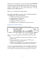
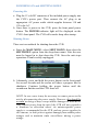
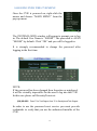
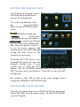
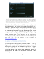
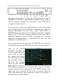
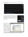
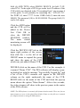
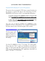
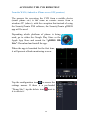
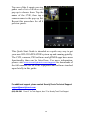
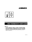
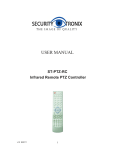
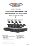
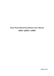
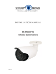
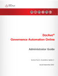
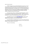
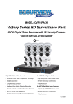
ST-HD-CVR4CH ST-HD-CVR8CH ST-HD-CVR16CH Professional Digital Video Recorders QUICK START GUIDE 1 Thank you for your purchase of this SecurityTronix HD-COAXINATOR Video Recorder (CVR). Documentation for this CVR comes in 2 formats; this printed Quick Start Guide and a full installation manual in PDF format on the included DVD disc. The full manual is also available online at: http://www.securitytronix.com/products This quick start guide covers the most essential information for getting the CVR up and running: Making connections and powering up. Logging into the CVR menus. Setting the time and Date. Setting the CVR to record 24/7. Making network connections and remote access. MAKING CONNECTIONS 8 channel CVR shown. All instructions also apply to 4ch and 16ch CVRs There are 3 connection types which MUST be made to use the CVR: 1) Up to 4, 8 or16 BNC video inputs from cameras (#1 in the image above). 2) Power for the CVR. Use the supplied 12VDC power supply (#9 in the image above). 3) Monitor output. Either the VGA connection (RGB video, # 4 above) or the HDMI connection (HD video #5 above). It is also strongly recommended to use the included USB mouse via the rear panel USB connection (#6). An Ethernet connection (#7) will also be needed for remote viewing of the CVR video. 2 POWERING ON and SHUTTING DOWN Powering On a. Plug the 12 volt DC connector of the included power supply into the CVR’s power port. Then connect the AC plug to an appropriate AC power outlet which supplies between 110 and 120 volts AC. b. Once there is power to the CVR, press the front panel power button. The POWER indicator light will be displayed on the CVR’s front panel. The CVR will sound a beep after startup. Shutting Down There are two methods for shutting down the CVR: a. Enter the MAIN MENU, select SHUT DOWN, then select the SHUTDOWN option from the drop-down menu. Note the user must be logged in to shut down the CVR. Once the unit stops operations it can be safely unplugged. b. Alternately, press and hold the power button on the front panel for several seconds and the screen will show a progress bar for shutdown. Continue holding the power button until the countdown finishes and the CVR shuts off. NOTE: In rare cases it may be necessary to remove power to the unit by disconnecting the power supply. However, this should be avoided as doing so may corrupt and/or damage the hard drive. Only remove power from the unit if the CVR will not respond to a shutdown as described above. An uninterruptable power supply is recommended for the CVR, and any power supplies for the cameras, to both protect against damage from sudden power outages and to maintain video surveillance during a power outage. 3 LOGGING INTO THE CVR MENU Once the CVR is powered on, right-click the mouse and choose “MAIN MENU” from the pop-up menu. The SYSTEM LOGIN window will appear to prompt you to log in. The default User Name is “888888”. The password is ALSO “888888” by default. Click “OK” and you will be logged in. It is strongly recommended to change the password after logging in the first time. NOTE: If the password has been changed then forgotten or misplaced, it will be virtually impossible for the user to log into the CVR. In this case please call SecurityTronix at: (800) 688-9282 Press “3” for Tech Support, then “2” for Securitytronix Tech Support. In order to use the password reset service you must provide credentials to verify that you are the authorized installer of the CVR. 4 SETTING THE TIME AND DATE Once logged in, the login screen will close and the Main Menu screen will be displayed: To set the time and date, click the icon on the Main Menu. On the SETTING menu, select On the GENERAL menu next to click on the year and use the pop-up number pad to set the current year. Repeat this to set the current Month and Day. The same process is used to set the hours, minutes and seconds in the next field, although setting the time down to the second is not necessary. If desired, the CVR can be set to automatically adjust the time for daylight savings time if your locality uses it. Click the DST button, click the ENABLE checkbox and set which days the DST becomes active and inactive. Click OK to close the DST settings box. Be certain to click OK to lock in the time settings before exiting the GENERAL SETTINGS menu. SETTING THE CVR TO RECORD From the Live Monitoring Screen, RIGHT-CLICK the mouse and choose RECORD from the pop-up menu. The RECORD MODE screen will appear: 5 The CVR will record 2 streams of different resolutions – the MAIN stream (full resolution) and the EXTRA stream (smaller resolution). The EXTRA STREAM is not necessary to use the CVR so for this Quick Start Guide we will not discuss it. Please refer to the full user’s manual for using the Extra Stream. If it is desired for all channels to record 24hrs / day every day, click the center button in the left-most row, which corresponds to ALL channels & MANUAL record. Click OK to save the setting and all channels will begin recording immediately. Conversely, to STOP all channels from recording, click the bottom-left button which corresponds to ALL channels & STOP. Clicking OK will then stop all channels from recording and prevent them from recording until further action is taken. If it is desired to use the schedule for recording, please refer to the full installation manual which shipped with the CVR. The full manual is also available at www.securitytronix.com. MAKING NETWORK CONNECTIONS To network the CVR for remote viewing, connect a Cat5 or higher grade network cable from the network port on the rear of the CVR (#7 below) to any available LAN port on a wired network switch which has connection to the internet. If the CVR only needs to be viewed from computers, tablets or phones within the same LAN, an internet connection is not necessary. 6 8 channel CVR shown. All instructions also apply to 4ch and 16ch CVRs Once the network cable is in place, the CVR must have its own IP ADDRESS, GATEWAY and SUBNET MASK settings made to coincide with the existing LAN and router so the CVR will be recognized on the network. For the purposes of this Quick Start Guide we will use Dynamic Host Configuration Protocol (DHCP) to automatically obtain the network information for the CVR. Ensure that DHCP is ENABLED on your router, for it to be able to provide a valid IP address to the CVR. Most common residential routers have DHCP enabled by default. If you are unable to determine this, proceed under the assumption that it is enabled and the next steps will confirm if it is enabled or not. Log in to the main menu and click the SETTING icon, then the NETWORK icon. The NETWORK menu will be shown as below: Click in the DHCP ENABLE checkbox so the box remains checked. Click SAVE to lock in this setting then restart the CVR. Once the CVR has restarted, return to this page. The settings shown on this network page will be correct. If the IP address is grayed-out or all zeroes, there may be a problem with the network cable or connections or the DHCP setting on the router may not be enabled. If this is the case please check all cables and connections and consult the router’s user manual to determine how to enable DHCP. 7 Forwarding Ports Write down the IP ADDRESS from the NETWORK screen of the CVR. This is the IP address which will be used to access the CVR “locally” from computers on the same network (usually in the same building as the CVR). This is also the address to be used for Port Forwarding should the CVR need to be accessed from outside the building network. The process for Port Forwarding will be different for each router. Consult your router’s manual for specific instructions regarding the process and follow these guidelines: 3 port numbers must be forwarded: port 80, port 37777 and port 37778. All 3 port numbers above must be forwarded for both “TCP” and “UDP” protocols. All 3 port numbers must be forwarded to the IP address of the CVR, which was obtained from the NETWORK page of the CVR in the “Forwarding Ports” step of page 8 of this guide. If the CVR is only to be accessed “locally”, it is not necessary to forward the ports in the router. Port Forwarding IS necessary to access the CVR from outside of the property at which the CVR is located. NOTE: The website www.portforward.com has useful resources for help with forwarding ports on a router. ACCESSING THE CVR REMOTELY From the LAN (on premises) On a computer running Windows XP, Windows 7 or Windows 8, install the Pro Surveillance System (PSS) Central Monitoring software which is included on the DVD disk provided with this CVR. Depending on the computer user’s access rights, the software may need to be installed and/or run “as administrator”. To do this, right-click on the software and choose “run as administrator” from the pop-up menu. Use the default user name “admin” and enter the password which is also “admin”. 8 Once the software opens, the main screen will be presented as shown below: Click on the CONFIG MANAGE tab in the right-hand pane, then from the pop-up menu choose DEVICE MANAGE. The DEVICE MANAGE window will appear as shown below. Ensure the DEVICE MANAGE tab is selected (1) and click the MANUAL ADD button (2). The ADD DEVICE window will appear (3 thru 11). Enter a name for the CVR, for example “Home CVR” (3). Click on the TYPE pulldown menu (4) and select “DVR”. The DISPLAY AMOUNT (5) field will become greyed out and is not used. For 9 field (6) ADD TYPE, select SINGLE DEVICE. In field (7) IP, select IPV4. To the right of IPV4 type in the local IP address of the CVR which was obtained in the “Forwarding Ports” step on page 8 of this guide. It will probably be something like “192.168.1.10”. For PORT (8) enter 37777. In the USER field (9) enter the user 888888. The password (10) is ALSO 888888. The group field (11) can be left empty. Click the ADD button and the CVR will be added to the Device List. Click OK to close the DEVICE MANAGE window. The main central monitoring screen will be displayed: Click the DEVICE LIST tab in the upper right portion of the screen, then click the + to the left of the GROUP name to expand the group and show the name of the CVR which was just added (Home CVR). DOUBLE-click on the name of the CVR. For this example, it is named “Home CVR”. The PSS software will display a popup dialog box with the message “Successfully Logged In!” and a list of the CVR’s cameras will appear in the DEVICE column on the right, underneath the name of the CVR. RIGHT-click on the name of the CVR and from the pop-up menu choose the option “Main Stream”. After a few seconds, the video streams will show in the preview panes in the center of the PSS software. NOTE: The PSS software is extremely full-featured and versatile. There are far too many features to cover in this Quick Start Guide. Please see the full user’s manual for complete details on using the PSS software. 10 ACCESSING THE CVR REMOTELY From the WAN (Windows PC access OFF premises) The process for accessing the CVR from a remote location via the internet is exactly the same as the instructions for ONPREMISES (LAN) access with 2 very important differences; 1) Instead of using the IP ADDRESS which is set in the CVR itself, the PUBLIC IP ADDRESS of the property will be used. 2) The CVR video port numbers must be forwarded in the router to which the CVR is connected. One easy way to find the PUBLIC IP ADDRESS of the property is to use a web browser on a computer connected to the same router as the CVR and navigate to the website: www.whatismyip.com The home page will appear with your IP address as shown at right (outlined in red for clarity). Use this IP ADRESS in step (7) on page 10 of this guide. Ensure that the CVR’s 3 ports are forwarded as described on page 8 of this guide and follow instructions for accessing the CVR via the SecurityTronix PSS application described on pages 9 through 11 of this guide. 11 ACCESSING THE CVR REMOTELY From the WAN (Android or iPhone access OFF premises) The process for accessing the CVR from a mobile device (smart phone etc) is the same as remote access from a windows PC (above), with the exception that instead of using the SecurityTronix PSS software, the SecurityTronix gDMSS app will be used. Depending which platform of phone is being used, go to either the Google Play Store or the Apple App Store and search for “gDMSS HD Lite”. Download and install the app. When the app is launched for the first time, it will present a blank monitoring screen: Tap the configuration icon to access the settings menus. If there is a pre-loaded “Demo Site”, tap the delete icon it to delete it. next to 12 Tap the ADD icon in the upper right corner to add a CVR and a device field will appear: In the NAME field, enter a name for the device, for example “Home CVR”. In the ADDRESS field, enter the PUBLIC IP address of the property where the device is located. This is the IP address obtained on page 12 of this guide. For the PORT field, leave the default port 37777 unless a new port was manually entered into the CVR, in which case enter that port instead. For the USER NAME and PASSWORD fields, enter the user name and password which are used to log into the CVR. The factory defaults for both of these fields are “admin”. In the MAX CHANNEL field, enter the number of cameras installed on the CVR. Once all fields are filled in, tap SAVE in the upper right corner and your CVR will be saved to the device list. Tap CONFIG to return to the live monitoring screen. 13 Tap one of the 4 empty preview panes and a list of devices will pop up to choose from. Tap the name of the CVR, then tap a camera name in the pop up list. Repeat this procedure for all 4 preview panes. This Quick Start Guide is intended as a quick easy way to get your new HD-COAXINATOR system up and running quickly. The CVR, cameras, PSS software and gDMSS apps have more functionality than can be listed here. For more information, please visit www.securitytronix.com/support for downloads of the full manuals for all of the equipment and software touched upon briefly in this guide. For additional support, please contact SecurityTronix Technical Support: [email protected] (800) 688-9282 Press “3” for Tech Support, then “2” for SecurityTronix Tech Support. 14