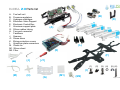
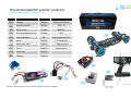
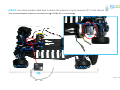
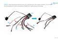
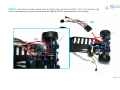
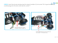
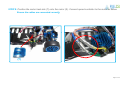
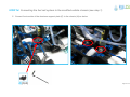
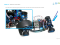
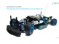
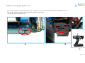
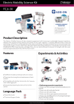
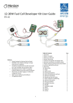
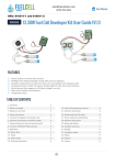
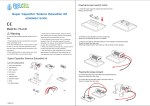
1
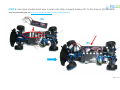
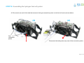
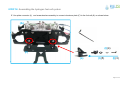
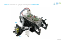
H-CELL 2.0
Assembly guide*
H CELL 2.0
H-CELL
20
21st century power system
for 1/10 RC hobby racing
*standard integration based on using TRF416/416X/417 chassis from TAMIYA
H-cell 2.0_AG_V2.8_EN
SAFETY INFORMATION please read before proceeding to assembly
Equipped with high performance running battery and motor, R/C car models are capable of speeds of over 50km/h.
O
Operating
ti
R/C models
d l in
i improper
i
areas may result
lt in
i accidents
id t causing
i
injury
i j
or property
t damage.
d
Follow the instructions outlined below to fully enjoy operating your R/C car.
1.
Operate R/C models in appropriate areas only.
a.
b.
c.
Never run R/C models on the road.
Never run R/C models in a crowded area or near small children.
Do not run R/C models in a narrow space or indoors.
2
2.
N
Never
ttouch
h any rotating
t ti parts
t such
h as wheels,
h l shafts
h ft or gears, as your finger,
fi
hair,
h i clothes
l th etc.
t may gett caught
ht leading
l di tto serious
i
iinjury.
j
3.
When not in use, always disconnect and remove battery and hydrogen canister.
4.
Do not disassemble the battery , the fuel cell, the HYDROSTIK PRO cartridges or cut the cables.
5.
Make sure you recharge the battery and fuel cell correctly, please follow the instructions.
6.
After use, battery retains heat, wait until it cools down before recharging. Please dispose of battery responsibly. Never put battery into fire.
7
7.
Immediately stop running if your R/C model gets wet,
wet as may cause short circuit.
circuit
8.
Do not tamper, disassemble or puncture the HYDROSTIK PRO cartridges.
9.
Keep assembled R/C MODEL and /or HYDROSTIK PRO cartridges away from fire, open flame, or heat source.
Page 2 of 44
*standard integration based on using TRF416/416X/417 chassis from TAMIYA
H-CELL 2.0 Parts list
A. Fuel cell unit
B. Pressure regulators
C. Hydrogen cartridges
pp
D. Electronic Valve Support
E. Electronic Control Box
F. Aluminum support plate
G. Silicon rubber tubing
p connector
H. Four-port
I. Fasteners
J. Spanner
J1. Screw driver
gp
protection covers
K. Wiring
L. Aluminum plate connectors
M. Plastic tie
M1. Silicon sheet
M2. Filter
(B)
(D)
(A)
(C)
(L)
(E)
(F)
(K)
(J)
(J1)
(1)
(2)
(3) (4)
(5) (6)
((I))
(M)
(H)
(G)
(M1)
(M2)
Page 3 of 44
Recommended RC vehicle* parts list
(not included in the H-Cell 2.0 kit)
Item
Supplier
Ref. number
(N)
Chassis
TAMIYA
TRF416/416X/417
(O)
Speed controller
TAMIYA
TBLE -01
(P)
Servo motor
Futaba
BLS551
(Q)
RC transmitter/receiver
Futaba
2PL
(R)
Lithium Battery
SE
2800-4000mAH/7.4V
(S)
Motor
TAMIYA
3.5T brushless
((T))
Motor heat sink**
TAMIYA
** Optional part
(U)
Tires
TAMIYA
Super slicks
What
is that?
(V)
Inner tube
TAMIYA
(W)
Hubcap
TAMIYA
(N)
(U)
(T)
(Q)
(R)
*standard integration based on using TRF416/416X/417 chassis from TAMIYA
(O)
(P)
Page 4 of 44
H-CELL 2.0
Standard Integration Design
Pressure Regulator
30W PEM Fuel Cell Stack
Electronic Controller
Hydrogen Cartridge
Fuel Cell On/Off Switch
Twin Air
Air-Supply
Supply (O2) Fans
Aluminum support plate
Heat Diffusion plate
RC transmitter/receiver
Speed
p
controller
Page 5 of 44
*standard integration based on using TRF416/416X/417 chassis from TAMIYA
STEP 1: Custom (adjusted) assembly of the TAMIYA TRF416/416X/417 CHASSIS*
A. Purchase all the necessary parts (see Recommended RC Vehicle Part list)
B. Follow the TRF416/416X/417 chassis assembly manual, but adjust with the
following steps:
Step 05: Cancel installation of “Drive Belt (Long)”
S
Step
10 Cancel
10:
C
l ““attaching
hi upper d
deck”
k”
Step 26: Installation of steering servo Futaba BLS 551** (see recommended, part list)
Step 27: R/C unit location should be changed (see step 2 in this manual)
Step 28: Cancel “securing cables”
Step
p 30: Cancel installation of B7 “rear body
y mounts”
*Although we recommend TRF416/416X/417 from TAMIYA and our aluminum support plate is designed around this model,
the H-cell 2.0 kit could be adapted to various RC vehicles and boats with some additional engineering.
Page 6 of 44
**We recommend Futaba BLS 551 due to its smaller size.
STEP 2: Use black double-sided tape to attach the antenna’s signal receiver (Q)* to the chassis (N).
*See recommended p
parts list (Horizon recommends using
g FUTABA 2PL for this assembly)
y)
(Q)
(Q)
Page 7 of 44
STEP 3: Place the wiring protection covers (K) onto the wires of the speed controller* (O) as below
*See recommended p
parts list ((Horizon recommends the TAMIYA TBLE-01 speed
p
controller for this assembly)
y)
(O)
(K)
(K)
(K)
Page 8 of 44
STEP 4: Use black double-sided tape to attach the speed controller* (O) to the chassis (N).
*See recommended parts list (Horizon recommends the TAMIYA TBLE-01 speed controller for this assembly)
(O)
(O)
Page 9 of 44
STEP 5: Use black double-sided tape to attach the speed controller (O)* switch to the chassis (N).
Paste speed controller On/Off switch
onto outer side of speed controller (O)
(O)
Page 10 of 44
STEP 6: Insert the red plug and grey plug from speed controller (O) into socket “B” of signal received (Q)
and black p
plug
g from the servo motor ((P)) into socket “1”.
( )
(O)
(P)
Place red plug from speed
controller (O) into socket “B”
(Q)
Place black plug from servo motor (P)
into socket “1” of receiver (Q)
Page 11 of 44
STEP 7: Insert the grey plug from speed controller (O) into socket “2” of the antenna’s signal receiver (Q).
Use a plastic tie (part M) to attach the cable to the chassis (N) together so wire doesn’t hang from chassis.
Make sure all the connections are correct. Pay attention to the plug direction.
Place black plug from speed controller (O)
into socket “2” of receiver (Q)
(M)
Page 12 of 44
STEP 8: Position the motor heat sink (T) onto the motor (S). Connect speed controller to the motor as below.
Ensure the cables are connected correctly.
y
(T)
Page 13 of 44
STEP 9: Use black double-sided tape to attach the (fully charged) battery (R)* to the chassis (N) as below.
*See
See recommended parts list, be sure to charge the battery before starting this step.
(R)
(R)
Page 14 of 44
STEP 10: Assembling the hydrogen fuel cell system
A. Disconnect one end of the tube that connects both gas connection points on the fuel cell (A) as shown below.
(A)
(A)
Gas
connection
points
Disconnect the tubing from only one of the connection points
Page 15 of 44
STEP 10: Assembling the hydrogen fuel cell system
B. Connect a new tubing (G) to the remaining free gas connection point on the fuel cell (A) as shown below.
(A)
(A)
2D
Page 16 of 44
STEP 10: Assembling the hydrogen fuel cell system
C. Connect each tube to the white plastic connector located on the electronic input and output valves as below.
Connect the filter(M2) between the fuel cell stack output and the output valve.
Make sure the small end of the filter is connected to the fuel cell stack output tube.
Make sure you connect your tubing to the valve’s
valve s white plastic connector and not the metallic one
one.
(A)
Electronic valves
White plastic connector point
Filter (M2)
Page 17 of 44
STEP 10: Assembling the hydrogen fuel cell system
D Turn the fuel cell (A) upside down and place the aluminum plate (F) exactly as shown below
D.
below.
Use the spanner
to connect the plate
to the fuel cell tightly.
(I)(1)
(A)
(F)
(F)
(A)
Make sure plate is positioned in the right direction
Page 18 of 44
STEP 10: Assembling the hydrogen fuel cell system
E. Use plate connector (L) and screw/washer assembly to connect aluminum plate (F) to the fuel cell (A) as shown below:
(A)
(I)(4)
(F)
(L)
(I)(5)
(I)(3)
Page 19 of 44
STEP 10: Assembling the hydrogen fuel cell system
F. Secure the aluminum plate to the fuel cell. You should obtain the assembly below:
(A)
(A)
(I)(4)
(I)(5)
(I)(1)
(I)(2)
Page 20 of 44
STEP 10: Assembling the hydrogen fuel cell system
G. Turn your fuel cell / aluminum support assembly upside down and use your spanner to tighten the nut to the assembly.
Page 21 of 44
STEP 10: Assembling the hydrogen fuel cell system
H. Turn your assembly upside down and position the valve holder (D) under the aluminum plate (F) exactly as below.
Use the spanner and two screws (I)(1) to connect the valve holder (D) to the aluminum plate (F).
Note: Do not tighten the screws yet as you will need to implant the electronic valves into the construction (next step).
(G)
(I)(1)
(D)
Page 22 of 44
STEP 10: Assembling the hydrogen fuel cell system
I.
Position the fuel cell’s ( A) OUTPUT VALVE (see stickers on the valves) on the aluminum plate (F) as below,
with the INPUT VALVE positioned below it, into the valve support unit (D).
Now tighten the screws that connect the valve support unit (D) to the aluminum plate.
(G)
Page 23 of 44
STEP 11: Assembling the hydrogen fuel cell system: COMPLETED!
(D)
(F)
Page 24 of 44
STEP 12: Connecting the HYDROSTIK hydrogen cartridges to the fuel cell system assembly
A. Connect four silicon rubber tubes (G) to the four-port connector (H) to obtain the assembly below.
(H)
3A
3B
(G)
Page 25 of 44
STEP 12: Connecting the HYDROSTIK hydrogen cartridges to the fuel cell system assembly
B. Connect two of the four tubes in the previous assembly to the two pressure regulators (B) as shown below.
(B)
Page 26 of 44
STEP 12: Connecting the HYDROSTIK hydrogen cartridges to the fuel cell system assembly
C. Connect one remaining tube to the input valve (located on top) of the fuel cell system assembly.
Page 27 of 44
STEP 12: Connecting the HYDROSTIK hydrogen cartridges to the fuel cell system assembly
D. Connect the (fully charged) HYDROSTIK PRO cartridges (C) to both pressure regulators (B).
Make sure to screw-in the canisters tightly when in use and be sure to disconnect them after use.
Note:
1. Only
O
use the canisters provided in the H-cell packaging.
2. Screw in the canisters quickly to avoid hydrogen gas release.
(B)
(B)
(C)
(C)
Page 28 of 44
STEP 12: Connecting the HYDROSTIK hydrogen cartridges to the fuel cell system assembly
E. Position both HYDROSTIK PRO cartridges (C) onto both canister support units on the system. Use the screw driver to tighten.
Note: Before position both HYDROSTIK PRO cartridges (C) onto both canister support units,
place a piece of silicon sheet (M1) on the support unit to protect the canister.
(C)
(M1)
Page 29 of 44
STEP 13: Connecting the electronic control box to the fuel cell system assembly
A. Remove cover from the electronic control box (E).
cover
System controller LED Indicator
Starting up Period Controller LED Indicator
Red LED flashes & Green LED off
Red LED lights & Green LED off
Red LED flashes & Green LED lights
Red LED off & Green LED lights
Status
Lithium battery voltage <6V
Fuel cell stack voltage <8.4V
Lithium battery voltage <7V
Normal Starting up
Operating Period
Controller LED Indicator
Red LED lights & Green LED off
Red LED flashes & Green LED flashes
Red LED lights & Green LED flashes
Red LED off & Green LED flashes
Red LED off & Green LED lights
Status
Fuel cell stack voltage ≤6.7V
Lithium battery voltage ≤6V
Fuel cell stack temperature ≥65C
Hydrogen pressure is too low, the load is cut off automatically
Normal operating
Page 30 of 44
STEP 13: Connecting the electronic control box to the fuel cell system assembly
B. Turn the fuel cell system assembly upside down, and place the electronic control box COVER on the aluminum support plate,
aligning the screw holes as below. Use the spanner and two screws (I)(1) to connect the box cover to the aluminum support plate (F).
(I)(1)
Page 31 of 44
STEP 13: Connecting the electronic control box to the fuel cell system assembly
C. Place the electronic box (E) over its cover and press down to connect to the rest of the fuel cell system assembly
C
assembly.
Make sure the pressure switch is connected to the four connecting port.
(E)
Pressure switch
Page 32 of 44
STEP 14: Connecting the fuel cell system to the modified vehicle chassis (see step 1)
A. Position the fuel cell system assembly onto the chassis as below, carefully aligning the screw connection points.
Use the spanner and screws (I)(5) to connect the support plate to the chassis.
Page 33 of 44
STEP 14: Connecting the fuel cell system to the modified vehicle chassis (see step 1)
B. Connect back section of the aluminum support plate (F) to the chassis (N) as below.
(I)(3,4)
Page 34 of 44
STEP 14: Connecting the fuel cell system to the modified vehicle chassis (see step 1)
C. Connect front section of the aluminum support plate (F) to the chassis (N) as below.
(I)(3,4)
Page 35 of 44
STEP 15: Electronic connections
A. Connect the fuel cell (A) to electronic control box (E).
Page 36 of 44
STEP 15: Electronic connections
B. Connect the electronic controller (A) to the motor (R).
Page 37 of 44
STEP 15: Electronic connections
C. Follow the steps below to connect the electronic controller to the Lithium Battery.
Page 38 of 44
STEP 16: Antenna connections
Push the antenna wire through the antenna tube. Insert the tube into the antenna base as below.
Page 39 of 44
CONGRATULATIONS!
Your hydrogen fuel cell hybrid RC car is now ready to go!
Page 40 of 44
STEP 17: Turning the system “on”
Turn the gas switch to the “ON” position (A). The fans on the H-cell activate and the blue LED lights turn on.
Turn on the receiver’s switch and activate the remote control unit.
Use the RC unit to steer the car.
A
B
C
Page 41 of 44
Additional recommendations (p
(please read carefully):
y)
1.The electronic valves have input and output connections. HYDROSTIK PRO cartridges should only be connected to
the input valve. If connected differently, the system will not function properly.
2. To avoid failure of the control box which can be caused by battery power leakage, please disconnect the lithium
battery from the control box after use.
3. To avoid damage to the fuel cell, disconnect the HYDROSTIK PRO cartridges from the pressure regulators after
use.
4.If the fuel cell has not been used for a long time, please operate the fuel cell system first for 3 minutes before
running the car.
5.Store the fuel cell unit assembly in a ziplock plastic or air-tight box during storage to keep its cells hydrated.
Page 42 of 44
Troubleshooting
1.After turning on the electronic control box switch, the red light in the control box flashes, while the green light
disappears. This indicates the Li-battery is drained and needs to be charged.
Solution:
1) Charge the battery.
2) Check the battery connection to the fuel cell system and reconnect it again.
2.After turning on the electronic control box switch, the red light in the control box flashes, while the green light
Is on. This is a warning indicator that the battery voltage is low. It will be drained if you keep on using it.
Solution:
1) Charge the battery.
2) If it is already a newly charged battery, please change to a new one as it may be
3. When you turn on the electronic controller box switch, the electronic controller box red light goes on, and the green
light goes off. It shows the fuel cell voltage is low, but the Li-battery’ voltage still meet the running requirement.
Solution:
1) HYDROSTIK cartridge is empty, use fully charged canisters.
2) Check the connection between the cartridge and the pressure regulator (B).
3) Check all the tubes connection.
4) Change a new fuel cell.
Note: When you encounter such problems, first be sure to turn off the electronic control box (E) switch before
attempting to resolve them
4. The red LED light flashes and then the system stopped automatically.
Solution:
Refill the metal hydride cartridge to the rated capacity.
Page 43 of 44
Troubleshooting (continued)
5. While the car is running, the red light inside the electronic control box turns on and the green light turns off. This is a
warning sign that the fuel cell voltage is low.
Solution:
1) Canister is empty, use fully charged canisters.
2) Check the connection between the canister and the pressure regulator.
3) Check all the tubes connection.
4) Change a new fuel cell.
6. While the car is running, the red light inside the electronic control box turns on and the green light flashes.
Solution:
1) Please run the car within the temperature of 5-40℃.
2) The fuel cell was destroyed – you must use a new fuel cell to run the car.
7. When the car is running, the both the red and green light flash inside the electronic control box.
Solution:
Charge the battery.
8. When you turn on the electronic controller box switch, no light turn on.
Solution:
Check all the connections, especially the connections between speed controller to the antenna’s signal receiver (see step 6).
- should you encounter additional problems, contact us at [email protected].
Page 44 of 44