1
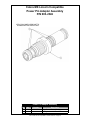
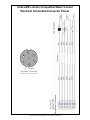
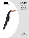
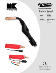
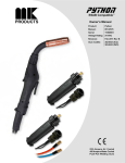
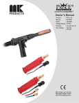
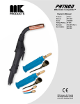
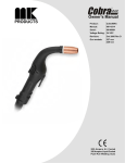
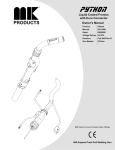
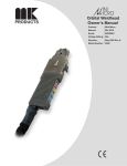
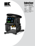
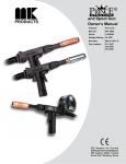
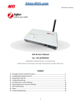
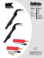
Lincoln Compatible™
Owner’s Manual
Shown with Classic Cup
Product:
Cobra® MX
Lincoln
Manual:
091-0627
Serial:
11060001
Voltage Rating: 24 VDC
Revision:
Sept 2013 Rev C
Gun models:
276-8xx A/C 1/4"
277-8xx A/C 3/8"
278-8xx W/C 1/4"
279-8xx W/C 3/8"
Shown with MAX Cup
175 Ampere Air Cooled, 1/4" tip
200 Ampere Air Cooled, 3/8" tip
225 Ampere Water Cooled, 1/4" tip
250 Ampere Water Cooled, 3/8" tip
Push-Pull Welding Guns
Table of Contents
Safety Considerations.........................................................................i-iii
Installation................................................................................ Section A
Technical Specifications......................................................................................1
Support Equipment Required..............................................................................1
Coolant Requirements........................................................................................1
Gun Lead Connections.......................................................................................1
Operation..................................................................................Section B
General...............................................................................................................2
Controls and Settings..........................................................................................2
Trigger Adjustment..............................................................................................2
Drive Roll and Idler Rolls....................................................................................3
Accessories..............................................................................Section C
Optional Kits........................................................................................................4
Conduits..............................................................................................................4
Snake Skins........................................................................................................4
Contact Tips........................................................................................................5
Gas Cups............................................................................................................6
Maintenance.............................................................................Section D
Periodic Maintenance.........................................................................................6
Recommended Spare Parts List.........................................................................7
Troubleshooting........................................................................Section E
Troubleshooting Guide........................................................................................9
Testing the Gun...................................................................................................9
Appendices...............................................................................Section F
Diagrams / Parts List......................................................................................... 11
Mechanical........................................................................................................12
Electrical...........................................................................................................29
Safety Warnings
Warranty
Declaration of Conformity for
European Community (CE) Products
Note
This information is provided for units with CE certification (see rating label on unit).
Manufacturer’s Name:
MK Products, Inc.
16882 Armstrong Ave.
Irvine, CA 92606
Declares that the product:
Cobra® MX Lincoln Compatible
conforms to the following Directives and Standards:
Directives
Low Voltage Directive: 2006/95/EC
Electromagnetic Compatibility (EMC) Directive: 2004/108/EC
Standards
Electromagnetic Compatibility, (EMC): EN 60974-10: 2007
Torches And Guns For Arc Welding, EN 60974-7: 2005
Safety Considerations
ELECTRIC ARC WELDING EQUIPMENT
CAUTION : READ BEFORE ATTEMPTING INSTALLATION, OPERATION
OR MAINTENANCE OF THIS EQUIPMENT
1-1 INTRODUCTION
This equipment is intended for ultimate
application by commercial/industrial
users and for operation by persons
trained and experienced in the use and
maintenance of welding equipment.
Operation should not be undertaken
without adequate training in the use of
such equipment. Training is available
from many public and private schools or
similar facilities.
Safe practices in the installation,
operation and maintenance of this
equipment requires proper training in the
art, a careful study of the information
provided with the equipment, and the
use of common sense. Rules for safe
use are generally provided by suppliers
of welding power sources, compressed
gas suppliers, and electrode suppliers.
Careful compliance with these rules will
promote safe use of this equipment.
The following Safety Rules cover some
of the more generally found situations.
READ THEM CAREFULLY. In case of
any doubt, obtain qualified help before
proceeding.
1-2 GENERAL PRECAUTIONS
A. Burn Prevention
ELECTRIC ARC WELDING PRODUCES
H I G H I N T E N S I T Y H E AT A N D
ULTRAVIOLET RADIANT ENERGY
WHICH MAY CAUSE SERIOUS AND
PERMANENT EYE DAMAGE AND
WHICH MAY DAMAGE ANY EXPOSED
SKIN AREAS.
Wear helmet with safety goggles or
glasses with side shields underneath,
appropriate filter lenses or plates
(protected by clear cover glass). This
is a must for welding or cutting (and
chipping) to protect the eyes from radiant
energy and flying metal. Replace cover
glass when broken, pitted, or spattered.
Medical first aid and eye treatment. First
aid facilities and a qualified first aid
person should be available for each shift
unless medical facilities are close by for
immediate treatment of flash burns of
the eyes and skin burns.
Wear protective clothing - leather (or
asbestos) gauntlet gloves, hat, and high
safety-toe shoes. Button shirt collar and
pocket flaps, and wear cuffless trousers
to avoid entry of sparks and slag.
Avoid oily or greasy clothing. A spark
may ignite them.
Flammable hair preparations should
not be used by persons intending to
weld or cut.
Hot metal such as electrode stubs and
work pieces should never be handled
without gloves.
Ear plugs should be worn when working
on overhead or in a confined space. A
hard hat should be worn when others
work overhead.
B. Toxic Fume Prevention
WARNING: The use of this product may
result in exposure to chemicals known
to the State of California to cause cancer
and birth defects or other reproductive
harm.
Adequate ventilation. Severe discomfort,
illness or death can result from fumes,
vapors, heat, or oxygen enrichment or
depletion that welding (or cutting) may
produce. Prevent them with adequate
ventilation. NEVER ventilate with
oxygen.
Lead-, cadmium-, zinc-, mercury-,
beryllium-bearing and similar materials,
when welded or cut, may produce
harmful concentrations of toxic fumes.
Adequate local exhaust ventilation must
be used, or each person in the area,
as well as the operator, must wear an
air-supplied respirator. For beryllium,
both must be used.
Metals coated with or containing
materials that emit toxic fumes should
not be heated unless coating is removed
form the work surface, the area is well
ventilated, or the operator wears an
air-supplied respirator.
Work in a confined space only while it is
being ventilated and, if necessary, while
wearing an air-supplied respirator.
Gas leaks in a confined space should be
avoided. Leaked gas in large quantities
can change oxygen concentration
dangerously. Do not bring gas cylinders
into a confined space.
short circuits.
If combustibles are in area, do NOT weld
or cut. Move the work if practicable,
to an area free of combustibles. Avoid
paint spray rooms, dip tanks, storage
areas, ventilators. If the work cannot
be moved, move combustibles at least
35 feet away, out of reach of sparks
and heat; or protect against ignition with
suitable and snug-fitting, fire-resistant
covers or shields.
Walls touching combustibles on opposite
sides should not be welded on (or cut).
Walls, ceilings, and floor near work
should be protected by heat-resistant
covers or shields.
Fire watcher must be standing by with
suitable fire extinguishing equipment
during and for some time after welding
or cutting if:
1. Appreciable combustibles (including
building construction) are within 35
feet.
2. Appreciable combustibles are further
than 35 feet, but can be ignited by
sparks.
3. Openings (concealed or visible) in
floors or walls within 35 feet may expose
combustibles to sparks.
4. Combustibles adjacent to walls,
ceilings, roofs, or metal partitions can be
ignited by radiant or conducted heat.
Leaving confined space, shut OFF
gas supply at source to prevent
possible accumulation of gases in the
space if downstream valves have been
accidentally opened or left open. Check
to be sure that the space is safe before
reentering it.
Hot work permit should be obtained
before operation to ensure supervisor’s
approval that adequate precautions have
been taken.
Vapors from chlorinated solvents can
be decomposed by the heat of the arc
(or flame) to form PHOSGENE, a highly
toxic gas, and other lung and eye irritating
products. The ultraviolet (radiant)
energy of the arc can also decompose
trichloroethylene and perchloroethylene
vapors to form phosgene. DO NOT
WELD or cut where solvent vapors can
be drawn into the welding or cutting
atmosphere or where the radiant energy
can penetrate to atmospheres containing
even minute amounts of trichloroethylene
or perchloroethylene.
An empty container that held
combustibles, or that can produce
flammable or toxic vapors when heated,
must never be welded on or cut, unless
container has first been cleaned in
accordance with industry standards.
C. Fire and Explosion Prevention
Causes of fire and explosion are:
combustibles reached by the arc, flame,
flying sparks, hot slag, or heated
material, misuse of compressed gases
and cylinders, and short circuits.
BE AWARE THAT flying sparks or falling
slag can pass through cracks, along
pipes, through windows or doors, and
through wall or floor openings, out of
sight of the goggled operator. Sparks
can fly many feet.
To prevent fires and explosion:
Keep equipment clean and operable,
free of oil, grease, and (in electrical
parts) of metallic particles that can cause
After work is done, check that area is
free of sparks, glowing embers, and
flames.
This includes: a thorough steam or
caustic cleaning (or a solvent of water
washing, depending on the combustible’s
solubility), followed by purging and
inerting with nitrogen or carbon dioxide,
and using protective equipment.
Water-filling just below working level may
substitute for inerting.
A container with unknown contents
should be cleaned (see paragraph
above). Do NOT depend on sense of
smell or sight to determine if it is safe
to weld or cut.
Hollow castings or containers must be
vented before welding or cutting. They
can explode.
Explosive atmospheres. NEVER weld or
cut where the air may contain flammable
dust, gas, or liquid vapors (such as
gasoline).
D. Compressed Gas Equipment
The safe handling of compressed gas
equipment is detailed in numerous
industry publications. The following
Cobra® MX Lincoln Compatible™ Owner's Manual - Page i
general rules cover many of the most
common situations.
1. Pressure Regulators
Regulator relief valve is designed
to protect only the regulator from
overpressure; it is not intended to protect
any downstream equipment. Provide
such protection with one or more relief
devices.
Never connect a regulator to a cylinder
containing gas other than that for which
the regulator was designed.
Remove faulty regulator from service
immediately for repair (first close cylinder
valve). The following symptoms indicate
a faulty regulator:
Leaks - if gas leaks externally.
Excessive Creep - if delivery pressure
continues to rise with downstream valve
closed.
Faulty Gauge - if gauge pointer does
not move off stop pin when pressurized,
nor returns to stop pin after pressure
release.
Repair. Do NOT attempt repair. Send
faulty regulators for repair to
manufacturer’s designated repair center,
where special techniques and tools are
used by trained personnel.
2. Cylinders
Cylinders must be handled carefully to
prevent leaks and damage to their walls,
valves, or safety devices:
Avoid electrical circuit contact with
cylinders including third rails, electrical
wires, or welding circuits. They can
produced short circuit arcs that may lead
to a serious accident. (See 1-3C)
ICC or DOT marking must be on each
cylinder. It is an assurance of safety
when the cylinder is properly handled.
Identifying gas content. Use only
cylinders with name of gas marked on
them; do not rely on color to identify gas
content. Notify supplier if unmarked.
NEVER DEFACE or alter name, number,
or other markings on a cylinder. It is
illegal and hazardous.
Empties: Keep valves closed, replace
caps securely; mark MT; keep them
separate from FULLS, and return
promptly.
Prohibited use. Never use a cylinder or its
contents for other than its intended use,
NEVER as a support or roller.
Locate or secure cylinders so they
cannot be knocked over.
Passageways and work areas. Keep
cylinders clear of areas where they may
be stuck.
to exceed 55 degrees C (130 degrees
F.) Cool with water spray where such
exposure exists.
Protect cylinders, particularly valves
from bumps, falls, falling objects, and
weather. Replace caps securely when
moving cylinders.
Stuck valve. Do NOT use a hammer
or wrench to open a cylinder valve that
cannot be opened by hand. Notify your
supplier.
Mixing gases. NEVER try to mix any
gases in a cylinder.
NEVER refill any cylinder.
Cylinder fittings should never be modified
or exchanged.
3. Hose
Prohibited use. Never use hose other
than that designed for the specified gas.
A general hose identification rule is: red
for fuel gas, green for oxygen, and black
for inert gases.
Use ferrules or clamps designed for
the hose (not ordinary wire or other
substitute) as a binding to connect hoses
to fittings.
No copper tubing splices. Use only
standard brass fittings to splice hose.
Avoid long runs to prevent kinks and
abuse. Suspend hose off ground to keep
it from being run over, stepped on, or
otherwise damaged.
Coil excess hose to prevent kinks and
tangles.
Protect hose from damage by sharp
edges, and by sparks, slag, and open
flame.
Examine hose regularly for leaks,
wear, and loose connections. Immerse
pressured hose in water; bubbles indicate
leaks
Repair leaky or worn hose by cutting
area out and splicing. Do NOT use
tape.
4. Proper Connections
Clean cylinder valve outlet of impurities
that may clog orifices and damage seats
before connecting regulator. Except
for hydrogen, crack valve momentarily,
pointing outlet away from people and
sources of ignition. Wipe with a clean,
lintless cloth.
Match regulator to cylinder. Before
connecting, check that the regulator
label and cylinder marking agree, and
that the regulator inlet and cylinder outlet
match. NEVER Connect a regulator
designed for a particular gas or gases to
a cylinder containing any other gas.
Transporting cylinders. With a crane,
use a secure support such as a platform
or cradle. Do NOT lift cylinders off the
ground by their valves or caps, or by
chains, slings, or magnets.
Tighten connections. When assembling
threaded connections, clean and smooth
seats where necessary. Tighten. If
connection leaks, disassemble, clean,
and retighten, using properly fitting
wrench.
Do NOT expose cylinders to excessive
heat, sparks, slag, and flame, etc. that
may cause rupture. Do not allow contents
Adapters. Use a CGA adapter (available
from your supplier) between cylinder
and regulator, if one is required. Use
two wrenches to tighten adapter marked
RIGHT and LEFT HAND threads.
Regulator outlet (or hose) connections
may be identified by right hand threads
for oxygen and left hand threads (with
grooved hex on nut or shank) for fuel
gas.
5. Pressurizing Steps:
Drain regulator of residual gas through
suitable vent before opening cylinder
(or manifold valve) by turning adjusting
screw in (clockwise). Draining prevents
excessive compression heat at high
pressure seat by allowing seat to open
on pressurization. Leave adjusting
screw engaged slightly on single-stage
regulators.
Stand to side of regulator while opening
cylinder valve.
Open cylinder valve slowly so that
regulator pressure increases slowly.
When gauge is pressurized (gauge
reaches regulator maximum) leave
cylinder valve in following position: for
oxygen and inert gases, open fully to
seal stem against possible leak; for fuel
gas, open to less than one turn to permit
quick emergency shut-off.
Use pressure charts (available from
your supplier) for safe and efficient
recommended pressure settings on
regulators.
Check for leaks on first pressurization
and regularly thereafter. Brush with
soap solution. Bubbles indicate leaks.
Clean off soapy water after test; dried
soap is combustible.
E. User Responsibilities
Follow all Safety Rules.
Remove leaky or defective equipment
from service immediately for repair. Read
and follow user manual instructions.
F. Leaving Equipment Unattended
Close gas supply at source and drain
gas.
G. Rope Staging-Support
Rope staging-support should not be
used for welding or cutting operation;
rope may burn.
1-3 ARC WELDING
Comply with precautions in 1-1, 1-2, and
this section. Arc Welding, properly done,
is a safe process, but a careless operator
invites trouble. The equipment carries
high currents at significant voltages.
The arc is very bright and hot. Sparks
fly, fumes rise, ultraviolet and infrared
energy radiates, weldments are hot,
and compressed gases may be used.
The wise operator avoids unnecessary
risks and protects himself and others
from accidents.
A. Burn Protection
Comply with precautions in 1-2.
The welding arc is intense and visibly
bright. Its radiation can damage eyes,
penetrate lightweight clothing, reflect
from light-colored surfaces, and burn
the skin and eyes. Skin burns resemble
Cobra® MX Lincoln Compatible™ Owner's Manual - Page ii
acute sunburn; those from gas-shielded
arcs are more severe and painful.
DON’T GET BURNED; COMPLY WITH
PRECAUTIONS.
1. Protective Clothing
Wear long-sleeve clothing in addition to
gloves, hat, and shoes. As necessary,
use additional protective clothing such
as leather jacket or sleeves, flameproof
apron, and fire-resistant leggings. Avoid
outer garments of untreated cotton.
Bare skin protection. Wear dark,
substantial clothing. Button collar to
protect chest and neck, and button
pockets to prevent entry of sparks.
2. Eye and Head Protection
Protect eyes from exposure to arc. Eyes
may be damaged by radiant energy
when exposed to the electric arc, even
when not looking in the direction of the
arc. Never look at an electric arc without
protection.
Welding helmet or shield containing a
filter plate shade no. 12 or denser must
be used when welding. Place over face
before striking arc.
Protect filter plate with a clear cover
plate.
Cracked or broken helmet or shield
should NOT be worn; radiation can be
passed through to cause burns.
Cracked, broken, or loose filter plates
must be replaced IMMEDIATELY.
Replace clear cover plate when broken,
pitted, or spattered.
Flash goggles with side shields MUST
be worn under the helmet to give some
protection to the eyes should the helmet
not be lowered over the face before an arc
is struck. Looking at an arc momentarily
with unprotected eyes (particularly a high
intensity gas-shielded arc) can cause a
retinal burn that may leave a permanent
dark area in the field of vision.
3. Protection of Nearby Personnel
Enclose the welding area. For production
welding, a separate room or enclosed
bay is best. In open areas, surround
the operation with low-reflective,
noncombustible screens or panels. Allow
for free air circulation, particularly at
floor level.
Viewing the weld. Provide face shields
for all persons who will be looking directly
at the weld.
Others working in area. See that all
persons are wearing flash goggles.
Before starting to weld, make sure that
screen flaps or bay doors are closed.
B. Toxic Fume Prevention
Comply with precautions in 1-2B.
Generator engine exhaust must be
vented to the outside air. Carbon
monoxide can kill.
C. Fire and Explosion Prevention
Comply with precautions in 1-2C.
Equipment’s rated capacity. Do not
overload arc welding equipment. It may
overheat cables and cause a fire.
Loose cable connections may overheat
or flash and cause afire.
Never strike an arc on a cylinder or
other pressure vessel. It creates a brittle
area that can cause a violent rupture
or lead to such a rupture later under
rough handling.
D. Compressed Gas Equipment
Comply with precautions in 1-2D.
E. Shock Prevention
Exposed electrically hot conductors or
other bare metal in the welding circuit,
or in ungrounded, electrically-HOT
equipment can fatally shock a person
whose body becomes a conductor. DO
NOT STAND, SIT, LIE, LEAN ON, OR
TOUCH a wet surface when welding
without suitable protection.
To protect against shock:
Keep body and clothing dry. Never
work in damp area without adequate
insulation against electrical shock. Stay
on a dry duckboard, or rubber mat when
dampness or sweat cannot be avoided.
Sweat, sea water, or moisture between
body and an electrically HOT part or grounded metal - reduces the body
surface electrical resistance, enabling
dangerous and possibly lethal currents
to flow through the body.
1. Grounding the Equipment
When installing, connect the frames of
each unit such as welding power source,
control, work table, and water circulator
to the building ground. Conductors must
be adequate to carry ground currents
safely. Equipment made electrically HOT
by stray currents may shock, possibly
fatally. Do NOT GROUND to electrical
conduit, or to a pipe carrying ANY gas or
a flammable liquid such as oil or fuel.
Three-phase connection. Check phase
requirement of equipment before
installing. If only three-phase power
is available, connect single-phase
equipment to only two wires of the
three-phase line. Do NOT connect the
equipment ground lead to the third (live)
wire, or the equipment will become
electrically HOT - a dangerous condition
that can shock, possibly fatally.
should be used to join welding cable
lengths.
3. Cables
Frequently inspect cables for wear,
cracks, and damage. IMMEDIATELY
REPLACE those with excessively worn
or damaged insulation to avoid possibly
lethal shock from bared cable. Cables
with damaged areas may be taped to
give resistance equivalent to original
cable.
Keep cable dry, free of oil and grease, and
protected from hot metal and sparks.
4. Terminals and Other Exposed
Parts
Terminals and other exposed parts of
electrical units should have insulating
covers secured before operation.
5. Electrode Wire
Electrode wire becomes electrically HOT
when the power switch of gas metal-arc
welding equipment is ON and welding
gun trigger is pressed. Keep hands
and body clear of wire and other HOT
parts.
6. Safety Devices
Safety devices such as interlocks
and circuit breakers should not be
disconnected or shunted out.
Before installation, inspection, or service
of equipment, shut OFF all power, and
remove line fuses (or lock or red-tag
switches) to prevent accidental turning
ON of power. Disconnect all cables from
welding power source, and pull all 115
volts line-cord plugs.
Do not open power circuit or change
polarity while welding. If, in an
emergency, it must be disconnected,
guard against shock burns or flash from
switch arcing.
Leaving equipment unattended. Always
shut OFF, and disconnect all power to
equipment.
Power disconnect switch must be
available near the welding power
source.
Before welding, check ground for
continuity. Be sure conductors are
touching bare metal of equipment frames
at connections.
If a line cord with a ground lead is provided
with the equipment for connection to
a switch box, connect the ground lead
to the grounded switch box. If a threeprong plug is added for connection to a
grounded mating receptacle, the ground
lead must be connected to the ground
prong only. If the line cord comes with a
three-prong plug, connect to a grounded
mating receptacle. Never remove the
ground prong from a plug, or use a plug
with a broken ground prong.
2. Connectors
Fully insulated lock-type connectors
Cobra® MX Lincoln Compatible™ Owner's Manual - Page iii
Section A Installation
Technical Specifications
Wire Capacity
.030" - .045" (0.8mm - 1.2mm) solid hard wire, and cored wire
.030" - 1/16" (0.8mm - 1.6mm) aluminum
Wire Speed
800 IPM (20.3 mpm) max
Duty Cycle - 60%
All ratings are using Argon gas
175 Amps/25 Volts
Air Cooled, 1/4" Tip (Model 276)
200 Amps/25 Volts
Air Cooled, 3/8" Tip (Model 277)
225 Amps/25 Volts
Water Cooled, 1/4" Tip (Model 278)
250 Amps/25 Volts
Water Cooled, 3/8" Tip (Model 279)
Support Equipment Required
•
•
•
•
C.V. or C.C. power source of sufficient capacity for your needs.
Regulated gas supply and hoses.
Properly sized power leads from power source to wire feeder and
ground.
Water source and hose capable of providing a minimum of 1 quart
(.95 liter) / min. at 45 p.s.i. when using water cooled guns.
Coolant Requirements
WARNING: Use only Cobra Coolant - failure to use coolant will void
warranty.
Use Cobra Coolant (Aluminum Protection),which does not contain reactive
sulphur or chlorine and does not react with copper, brass or aluminum. The
Cobra Coolant is available in quantities of 1 gallon (P/N 931-0060), 5 gallon
(P/N 931-0060-5GAL), or a case of 4 gallons each (P/N 931-0060-4).
The coolant flow rate should be a minimum of 10 GPH (1 qt/min) between
35 and 45psi. Contact the re-circulator manufacturer for specifications on
pressure.
Gun Lead Connections
Power Cable - Air Cooled
A #2 power cable is used on the Cobra MX Lincoln Compatible gun. The
gun and Power Pin ends of the cable are stripped to the copper strands and
wrapped with a copper strip. A setscrew holds the cable securely in the gun
body and in the Power Manifold with torque requirements of 55-60 in-lb.
Power Cable - Water Cooled
The Cobra MX Lincoln Compatible water cooled gun utilizes a power/water
cable with a #6 AWG cable inside a 5/16” diameter hose.
The power cable ends are threaded fittings which screw into the gun body
and the Power Manifold. These connections utilize a conductive sealant and
are tightened with torque requirements of 100 + 5 IN-LB.
Conduit
The Cobra MX Lincoln Compatible comes standard with a poly-lined conduit,
for feeding aluminum wire. The longer fitting with a shallow groove is used
on the gun end. A set screw located on top of the gun handle secures the
conduit in place. The cabinet end of the conduit is secured into the Power Pin
connector with a set screw.
Gas Hose
The BLACK gas hose is pushed over a barbed fitting on the end of the gun
body and secured by twisting the hose retainer to the end of the hose (shown
next page). The opposite end of the BLACK hose is pushed over a barbed
fitting in the Power Pin. The hose retainer is re-usable and can be removed
and re-installed as needed.
Cobra® MX Lincoln Compatible™ Owner's Manual - Page 1
Coolant Connections
If so equipped, the ends of the coolant hose push over a barbed fitting on
the end of the gun body and are secured by twisting the hose retainer to the
end of the hose. The hose retainer is re-usable and can be removed and
re-installed as needed.
The BLUE coolant supply hose pushes over a barbed fitting on the end of
the gun body and is secured by twisting the hose retainer to the end of the
hose. The hose retainer is re-usable and can be removed and re-installed as
needed.The opposite end of the BLUE hose pushes into a threaded coolant
fitting.
The RED coolant return hose pushes over the barbed fitting in the Power
Manifold. The opposite end of the RED hose pushes into a threaded return
hose of the coolant recirculator.
Both threaded fittings on the end of the BLUE and RED hoses are standard
left-hand thread. MK Products compatible guns have interchangeable fittings,
so you can match as needed for your cooler. Both types of fittings require a
hose retainer.
431-1898
5/16” Hose Retainer
431-1910
Quick Connect Fitting
431-1893*
Nipple
753-3379*
Left-Hand Threaded Fitting
*Must be ordered together
Control Cable
A multi-conductor control cable is used on the Cobra MX Lincoln Compatible.
The gun end of the cable is secured with a cable clamp and the wires are
connected to the potentiometer, the micro switch, the motor and the gun
body mechanically. Slack is left in the electric cable as it exits the back of the
gun to prevent cable and/or wire breakage. The cabinet end has a seven pin
"W" clocked amphenol connector.
Section B Operation
General
The Cobra MX Lincoln Compatible gun maintains a constant, steady, uniform
wire feed speed, regardless of curved or looped wire conduit. The constant
push exerted by the slave motor in the cabinet, combined with the pull of
the gun motor, causes the wire to literally float friction-free through the wire
conduit. The 24VDC gun motor is controlled by a
Trigger Sensitivity Adjustment
Screw Location
three and three-quarter (3-3/4) turn potentiometer in
the gun handle.
Controls and Settings
Potentiometer
The laterally-positioned potentiometer is located in
the lower end of the handle, providing up to 800 ipm
with 3-3/4 turns.
Micro Switch
The micro switch assembly consists of the micro
switch, and leads.
Trigger Sensitivity
The amount of trigger lever travel can be shortened
for a quicker or more responsive action.
A more sensitive trigger lever is produced by
reducing the gap between the trigger lever and the
micro switch lever. By turning-in the trigger sensitivity
Cobra® MX Lincoln Compatible™ Owner's Manual - Page 2
Screw adjusted out of trigger,
pre-setting the micro-switch
lever for shorter motion
sensitivity.
adjustment screw, it closed the gap between the trigger lever and the micro
switch lever.
This will enable the operator to increase the sensitivity of the trigger lever.
Sensitivity Adjustment
With the wire feeder turned on (with or without welding wire loaded), turn the
screw in until the micro-switch is activated. Once activated, the torch and
wire feeder motors will begin feeding wire. Retract the screw accordingly until
the system is deactivated and adjusted to the operators' liking.
Drive Roll and Idler Rolls
General
The Cobra MX Lincoln Compatible gun comes standard with a knurled drive
roll and a grooved idler roll, which will handle both hard wire and aluminum
wire with diameters of .030 to 1/16 inch and steel from .030 to .045 inches.
Optional insulated V-groove drive rolls are also available for aluminum wire if
desired (see optional kits).
Drive roll tension is accomplished with a unique spring-loaded pressure
screw. The Cobra MX Lincoln Compatible comes from the factory with
the pressure adjustment screw preset. NO ADJUSTMENT is
required for all sizes and types of wires.
Drive Roll Installation/Removal
Note: Neither of the handles needs to be removed to access the drive or
idler rolls.
Cam Lever
1. Pull the cam lever away from the idler roll.
This will relieve the pressure against the
drive roll (as shown in Figure 1).
Figure 1
2. Align the drive roll removal tool (P/N 9310100) over the flats of the drive roll (as
shown in Figure 2). Hold the gun with one
hand or on a table top, with the other hand
give the removal tool a quick snap-turn in
the CLOCKWISE DIRECTION.
3. Once the drive roll is loose, continue to
Figure 2
spin drive roll in the clockwise direction to
remove the drive roll from the gun.
4. Install a new drive roll on the left-hand threaded shaft. The drive roll will
self-tighten when it is feeding wire.
Idler Roll Installation and Removal
(Reference Figure 3)
1. Using a slot type screwdriver, loosen idler screw, taking care not to lose
lock washer under idler roll.
2. Insert new idler roll and lock washer onto screw, insuring that idler groove
is toward top and lock washer is beneath.
3. Tighten.
Figure 3
NOTE: Lock washer must be under idler roll or it will not turn freely.
Cobra® MX Lincoln Compatible™ Owner's Manual - Page 3
Section C Accessories
Optional Kits
Insulated Drive Roll Kits are used to prevent preheating of the aluminum wire
which may soften it and clog the liner. This picking up of current at the drive
rolls rather than at the contact tip is usually not a problem unless using too
large of a contact tip or excessively oxidized aluminum wire.
Insulated Grooved Drive Roll Kit................................................... 005-0715
For .030" (0.8mm) dia. aluminum wire. Includes insulated groove drive roll
and insulated idler roll assy.
Insulated Grooved Drive Roll Kit................................................... 005-0716
For .035" (0.9mm) dia. aluminum wire. Includes insulated groove drive roll
and insulated idler roll assy.
Insulated Grooved Drive Roll Kit................................................... 005-0717
For .040" (1.0mm) dia. aluminum wire. Includes insulated groove drive roll
and insulated idler roll assy.
Insulated Grooved Drive Roll Kit....................................................005-0718
For 3/64" (1.2mm) dia. aluminum wire. Includes insulated groove drive roll
and insulated idler roll assy.
Insulated Grooved Drive Roll Kit....................................................005-0719
For .062" (1.6mm) dia. aluminum wire. Includes insulated groove drive roll
and insulated idler roll assy.
Handle Kit.......................................................................................... 005-0725
Includes left and right handles, screws and drive roll door.
Trigger Kit..........................................................................................005-0726
Trigger kit includes sensitivity adjustment screw replacement for all Cobra
MX Lincoln Compatible /CobraMAX™ guns.
Barrel Insulator Replacement Kit....................................................005-0696
Includes replacement barrel insulator and taper lock nut.
Conduits
Flat spiral steel conduit for steel & cored wire.
15 ft./4.5m...................................................................................... 615-0621-15
25 ft./7.6m...................................................................................... 615-0621-25
35 ft./10.7m.................................................................................... 615-0621-35
50 ft./15.2m.................................................................................... 615-0621-50
Optional nickel tube liner................................................................. 431-2030
Snake Skins
Snake Skin protective covers are now standard on all guns. You may order
spare replacement covers to protect the lead assy of the gun when the
factory one becomes damaged or worn. It can easily be replaced in the field
by means of Velcro©.
Snake Skin Cover 13ft (for 15ft leads)................................................931-0110
Snake Skin Cover 23ft (for 25ft leads)............................................... 931-0122
Snake Skin Cover 33ft (for 35ft leads)............................................... 931-0132
Snake Skin Cover 48ft (for 50ft leads)............................................... 931-0123
Gas Valve Removal Tool
Gas valve removal is performed by using P/N 931-0105 Gas Valve Removal
Tool. This multifunctional tool has been slotted on one side to encompass
and conform to the gas valve stem and seat into the slotted gas valve body
as seen in Figures 1 and 2. Removal of the gas valve can be accomplished
by turning the gas valve tool counter clockwise. Reinstall by turning clockwise. The tool doubles as a bottle opener.
Cobra® MX Lincoln Compatible™ Owner's Manual - Page 4
Figure 2
Figure 1
Gas Valve Removal Tool
Contact Tips
(Models 277 and 279)
Wire Size
Heavy Duty Contact Tip - 3/8" Diameter*
Tip ID
Arc
Tip Length
Part No.
.030” (0.8mm)
.041” (1.0mm)
.035” (0.9mm)
.044” (1.1mm)
Spray
Short
Spray
1.57” (39.9mm)
1.82” (46.2mm)
1.57” (39.9mm)
.035" (0.9mm) .044" (1.1mm)
.045" (1.1mm) .053" (1.35mm)
3/64” (1.2mm) .053” (1.35mm)
Short
Short
Spray
1.82” (46.2mm)
1.82” (46.2mm)
1.57” (39.9mm)
621-0390-25
621-0396-25
621-0391-25
621-0391-250†
621-0391-500††
621-0397-25
621-0398-25
621-0392-25
621-0392-250†
3/64” (1.2mm)
.060” (1.5mm)
Spray
1.57” (39.9mm)
1/16” (1.6mm)
.074” (1.9mm)
.085” (2.16mm)
Spray
Spray
1.57” (39.9mm)
*Use of tip removal tool is recommended
**This size tip furnished with gun
†
621-0392-500††
621-0393-25**
621-0393-250†
621-0393-500††
621-0394-25
621-0395-25
Also sold in quantities of 250
Also sold in quantities of 500
††
(Models 276 and 278)
1/4" Diameter Contact Tip*
Wire Size
Tip ID
Arc
Tip Length
.023” (0.6 mm)
.023” (0.6 mm)
.030” (0.8 mm)
.030” (0.8 mm)
.035"/.030”
(0.9 mm /0.8 mm)
.035” (0.9 mm)
.031” (0.8 mm)
.031” (0.8 mm)
.036” (0.9 mm)
.037” (0.9 mm)
.041” (1.0 mm)
Spray
Short
Spray
Short
Spray
1.50” (38.1 mm)
1.75” (44.5 mm)
1.50” (38.1 mm)
1.75” (44.5 mm)
1.50” (38.1 mm)
621-0057-25
621-0328-25
621-0325-25
621-0326-25
621-0076-25
.044” (1.1 mm)
Spray
1.50” (38.1 mm)
.035” (0.9 mm)
.035” (0.9 mm)
3/64” (1.2 mm)
3/64” (1.2 mm)
.041” (1.0 mm)
.044” (1.1 mm)
.053” (1.35 mm)
.060” (1.5 mm)
Short
Short
Spray
Spray
1.75” (44.5 mm)
1.75” (44.5 mm)
1.50” (38.1 mm)
1.50” (38.1 mm)
1/16” (1.6 mm)
1/16” (1.6 mm)
.074” (1.9 mm)
.085”(2.1 mm)
Spray
Spray
1.50” (38.1 mm)
1.50” (38.1 mm)
621-0001-25
621-0001-250†
621-0001-500††
621-0077-25
621-0002-25
621-0327-25
621-0003-25**
621-0003-250†
621-0003-500††
621-0075-25
621-0153-25
**This size tip furnished with gun
* All tips sold in quantities of 25
†
Part No.
Also sold in quantities of 250
Also sold in quantities of 500
††
Cobra® MX Lincoln Compatible™ Owner's Manual - Page 5
(Models 277 and 278)
Spring Loaded Contact Tip - 3/8” Diameter
Wire Size
Tip ID
Arc
Tip Length
Qty Part Number
.030” (0.8 mm)
.035” (0.9 mm)
.041” (1.0 mm)
.044” (1.1 mm)
Spray 1.57” (39.9 mm) EA
Spray 1.57” (39.9 mm) EA
621-0331
621-0332
3/64” (1.2 mm)
1/16” (1.6 mm)
.060” (1.5 mm)
.074” (1.9 mm)
Spray 1.57” (39.9 mm) EA
Spray 1.57” (39.9 mm) EA
621-0334
621-0335
MAX Cups
Classic Cups
(Models 277 and 279)
(Models 276 and 278)
Cup I.D.
Part No.
Cup I.D.
Part No.
#6, 3/8" (9.5mm)
621-0420
#5, 1/4" (6.4mm)
621-0079
#8, 1/2" (12.7mm)
621-0421*
#6, 3/8" (9.5mm)
001-0137-4†
#10, 5/8" (15.9mm)
621-0422
#8, 1/2" (12.7mm)
001-0138-4*†
#10, 5/8" (15.8mm)
001-0139-4†
*standard - furnished with gun
†
sold in packs of 4 each
Tip Extender
Tip Extenders and Gun Barrel Liners
Part Number
Description
931-0137
Teflon liner package, 5 pieces
615-0338
Steel wire only, .030 - .1/16" (0.8 - 0.9mm)
621-0424
Cobra MX Lincoln Compatible tip extender (Air cooled barrel only)
615-0250
Section D Spiral steel liner for tip extender
Maintenance
Periodic Maintenance
Your Cobramatic system is designed to provide years of reliable service.
Maintenance of the gun will normally consist of a general cleaning of the wire
guide system, including barrels, drive rolls, and conduits at regular intervals.
Remove spatter build-up from inside of nozzles with a hardwood stick.
The only parts on the Cobramatic system that are subject to normal wear are
the conduit, contact tips, gas cups, front body liners, wire guides, drive and
idler rolls. A supply of these parts should be maintained on hand.
The number of units in operation and the importance of minimal down time
will determine to what extent spare parts should be stocked on hand. See
the recommended spare parts list for the most commonly replaced parts.
If repairs do become necessary, qualified shop maintenance personnel can
easily replace any part.
Maintenance Tools
Tool
Part Number
Contact Tip Removal Tool
931-0044
Drive Roll Removal Tool
931-0100
Cobra® MX Lincoln Compatible™ Owner's Manual - Page 6
Recommended Spare Parts List
Qty.
Part No.
Description
1
615-0620-15
Conduit - 15 ft
1
615-0620-25
Conduit - 25 ft
1
615-0620-35
Conduit - 35 ft
1
615-0620-50
2
005-0726
Conduit - 50 ft
Trigger Assy Kit
1
005-0725
Handle Kit
10
511-0101
Drive Roll
5
005-0686
Idler Roll Kit
DRIVE ROLL REMOVAL TOOL
931-0100
KNURLED DRIVE ROLL
511-0101
IDLER ROLL
511-0001
(.030" - 3/64")
IDLER ROLL
511-0113
(.023")
MICRO SWITCH ASSY
003-2274
Cobra® MX Lincoln Compatible™ Owner's Manual - Page 7
Section E Troubleshooting
Trouble
No wire feed at
gun, feeder not
operating, i.e. no
slave motor or
brake solenoid.
No wire feed
at gun, feeder
operating properly.
Wire feeds, but
welding wire is not
energized.
Wire feeds
erratically.
Wire feeds one
speed only.
Wire walks out of
drive rolls.
Cause
Input power fuse in
feeder/control box blown
Remedy
Replace fuse.
Micro-switch defective/not Replace switch. Check
being activated
switch for operation.
Broken electrical cable
Check micro-switch wires
for continuity.
Motor control fuse in
feeder/control box blown
Check motor leads for
shorts; then replace fuse.
Bad potentiometer
Check potentiometer with
meter.
Broken electrical cable.
Check motor and
potentiometer wires for
continuity.
Bad speed control/PCB.
See specific cabinet/
control box owner's
manual for speed control
operation.
Loose or no cable
connections.
Check all power
connections.
Check power supply
owner's manual for
Contactor control cable
location and type of
loose or in wrong position
contactor signal required,
i.e. closing or 115VAC.
Welding power source
Check power source.
Dirty or worn conduit
Blow out or replace
conduit.
Wrong size contact tip
See contact tip table.
Idler roll stuck
Check for lock washer
under idler roll, or replace
if damaged.
Bad potentiometer
Check with meter.
Broken electrical cable
Check potentiometer
wires for continuity or
short.
Bad speed control
See specific cabinet/
control owner's manual for
speed control operation.
Idler roll upside-down
Place groove in idler roll
toward top.
Rear wire guide missing
Replace wire guide.
Cobra® MX Lincoln Compatible™ Owner's Manual - Page 8
Troubleshooting Guide
Regardless of which gun or feeder used, all MK Products’ push-pull guns
operate on the same principle. The slave motor in the feeder runs at a
fast,constant speed, but has very low torque. It is always trying to feed
more wire than the gun motor wants, and when the motor gets all it wants, it
slows the slave motor, preventing a bird’s nest. Because of the low torque
produced by the slave motor, a brake system is used to prevent wire overrun
rather than tension. The drag adjustment in the feeder is used simply to
keep the wire slightly taut, so it will not pull off the spool while feeding wire.
The high torque 24VDC gun motor is controlled by a solid state speed
control located in the feeder, and a pot located in the gun. The gun motor,
potentiometer, and micro switch are connected to the cabinet/control box via
a control cable and Amphenol connector. If this cable becomes damaged, a
variety of symptoms can occur, depending on which wire(s) break. To test,
check each wire for continuity and shorts.
Remember, the micro switch in the gun activates both the slave motor and
gun motor circuits in the cabinet. Therefore, if the slave motor and brake
solenoid operate, but the gun does not, look more toward the gun motor’s 24
V circuits, speed control, control cable, or the gun motor. If nothing operates,
look more toward the slave motor’s input, micro switch leads, or micro switch.
Testing The Gun
Reference the "W" clocked gun wiring diagram on
the Cobra MX electrical diagram for information
about pin-outs and locations.
Motor Check
Remove the gun connector from the cabinet.
Using the gun Amphenol connector, check the resistance across pins “A”
and “B” (motor leads).
If an open circuit (more than K ohms) or short exist (less than 2 ohms)
exists, check the motor leads and motor independently.
Testing the Potentiometer - “W” Clocked
Using the gun amphenol connector, check the resistance across pin “D”
(wiper) and pin “C”. The resistance should vary from 0 - 5K ohms as the
potentiometer is turned.
Check the resistance across pin “D” (wiper) and pin “G”. The resistance
should vary from 5K - 0 ohms as the potentiometer is turned.
Testing the Micro Switch
Using the gun amphenol connector, check for continuity across pins “E” and
“F” when the trigger is pressed.
For 7 Pin only
Cobra® MX Lincoln Compatible™ Owner's Manual - Page 9
This page intentionally left blank
Section F
Appendices
Diagrams / Parts List
Exploded View........................................................................... 12
Bill of Material............................................................................ 13
Front Body Assembly................................................................. 14
Rear Body Assembly, Air Cooled............................................... 15
Rear Body Assembly, Water Cooled.......................................... 16
Classic Cup Barrel Assembly, Air Cooled.................................. 17
Classic Cup Barrel Assembly, Water Cooled............................. 18
MAX Barrel Assembly, Air Cooled.............................................. 19
MAX Cup Barrel Assembly, Water Cooled................................. 20
Lead Assembly, Air Cooled........................................................ 21
Lead Assembly, Water Cooled................................................... 22
Spiral Wrap Installation.............................................................. 23
Power Pin Adapter Assembly.................................................... 26
Power Manifold Assembly, Air Cooled....................................... 27
Power Manifold Assembly, Water Cooled.................................. 28
Electrical.................................................................................... 29
Cobra® MX Lincoln Compatible™ Owner's Manual - Page 11
Cobra MX Lincoln Compatible Head Assembly
Air Cooled
Water Cooled
Cobra® MX Lincoln Compatible™ Owner's Manual - Page 12
Cobra® MX Lincoln Compatible™ Owner's Manual - Page 13
003-2397
003-2398
211-0085
211-0080
1
1
1
1
1
1
1
3
4
5
1
2
1
3
8
9
10
11
7
6
005-0726
1
2
320-0101
319-0258
319-0254
301-0093
003-2274
003-2190
003-2141
002-0629
1
1
Part No.
Qty.
No.
Scr Button 4-40 x 3/16 SST
Scr FH Phil 4-40 x 5/8 SST
Scr FH Phil 82 4-40 x 3/8 SST
Boot Torch
High Speed Motor (optional)
Standard Motor
Assy Rear Body, WC
Assy Rear Body, AC
Trigger Kit
Assy Switch
Assy Pot
Front Body
Assy Cam Idler Arm
Description
24
23
22
21
20
19
18
17
16
15
14
13
12
No.
1
1
1
1
1
1
1
2
5
4
7
5
4
Qty.
005-0725
437-0253
435-1585
431-1892
421-0452
405-1312
405-0706
338-0034
338-0022
338-0014
333-0261
333-0260
Part No.
Handle Kit: Includes line items 14, 20,
and 22
Door Molded
Strap Motor
Scr Shoulder 1/8 Door MX
Pin Dowel 3/32 x 0.80 LG
Label Warning
Label Serial Plate
Scr Shc 8-32 x 1/2 SST
Scr Shc 6-32 x 3/8 SST
Scr Shc 4-40 x 1/2 SST
Wshr, Spr, LK #8 SST
Wshr, Spr, LK #6 SST
Description
Cobra MX Lincoln Compatible Air Cooled and Water Cooled Head Assembly
Cobra MX Lincoln Compatible
Front Body Assembly
P/N 003-2141
Front Body Assembly
No.
Qty.
Part No.
1
-
-
Not available separately
2
-
-
Not available separately
3
1
325-0206 Scr Ph 10-24-3/8
4
1
333-0082 Washer Lock 10
5
1
419-0092 Spring Comp 0.31 OD x 0.20 ID
6
1
421-0525 Pin Dowel 1/8 x 7/8 Sst
7
1
431-1663 Scr Adjust Idler
8
1
431-1598 Arm Idler Cobra
9
1
511-0001 Assy Idler Wire Feed
10
1
511-0101 Drive Roll Gold
Description
Cobra® MX Lincoln Compatible™ Owner's Manual - Page 14
Cobra MX Lincoln Compatible Rear Assembly
Air Cooled
P/N 003-2397
Air Cooled Rear Body Assembly
No.
Qty.
Part No.
1
1
003-2199
2
-
-
Not available separately
3
2
303-0096
O-Ring .145 ID x .07 W
4
1
321-1082
Set Screw Flat 1/4-20 5/16 SST
5
1
321-1104
Set Screw Conduit
6
2
411-0045
Tie Wrap
Description
Assy Gas Valve w/ Mod Valve
Cobra® MX Lincoln Compatible™ Owner's Manual - Page 15
Cobra MX Lincoln Compatible Rear Assembly
Water Cooled
P/N 003-2398
Rear Body Assembly - Water Cooled
No.
Qty.
Part No.
1
1
003-2199
Description
Assy Gas Valve w/ Mod Valve
2
-
-
Not available separately
3
6
303-0096
O-Ring .145 ID x .07 W
4
1
321-1104
Set Screw Conduit
5
2
411-0045
Tie Wrap (not shown for clarity)
Cobra® MX Lincoln Compatible™ Owner's Manual - Page 16
Cobra MX Lincoln Compatible Classic Cup
Barrel Assembly
Air Cooled, P/N 003-2341
*Apply silicone lubricant to item
3 before installing.
Classic Cup Barrel Assembly - Air Cooled
No.
Qty.
Part No.
1
1
001-0138
2
-
-
3*
2
303-0096
O-Ring .145 ID x .07W
4
1
437-0299
Insulation Barrel
5
1
931-0137
5-Piece Teflon Liner Package
6
1
621-0003
Tip 0.06 x 0.25 OD
Description
Assy Gas Cup MK #8
Not available separately
Cobra® MX Lincoln Compatible™ Owner's Manual - Page 17
Cobra MX Lincoln Compatible Classic Cup
Barrel Assembly
Water Cooled, P/N 003-2342
*Apply silicone lubricant to item
3 before installing.
Classic Cup Barrel Assembly - Water Cooled
No.
Qty.
Part No.
1
1
001-0138
2
-
-
3*
6
303-0096
O-Ring .145 ID x .07W
4
1
437-0299
Insulation Barrel
5
1
931-0137
5-Piece Teflon Liner Package
6
1
621-0003
Tip 0.06 x 0.25 OD
Description
Assy Gas Cup MK #8
Not available separately
Cobra® MX Lincoln Compatible™ Owner's Manual - Page 18
Cobra MX Lincoln Compatible MAX Cup
Barrel Assembly
Air Cooled, 003-2343
*Apply silicone lubricant to item
2 before installing.
MAX Cup Barrel Assembly - Air Cooled
No.
Qty.
Part No.
1
-
-
2*
6
303-0096
3
1
437-0299
Insulation Barrel
4
1
931-0137
5-Piece Teflon Liner Package
5
1
621-0393
Tip HD Spray .060
6
1
621-0421
Assy Gas Cup #8 CobraMAX
Description
Not available separately
O-Ring .145 ID x .07W
Cobra® MX Lincoln Compatible™ Owner's Manual - Page 19
Cobra MX Lincoln Compatible MAX Cup
Barrel Assembly
Water Cooled, 003-2344
*Apply silicone lubricant to item
2 before installing.
MAX Cup Barrel Assembly - Water Cooled
No.
Qty.
Part No.
1
-
-
2*
6
303-0096
O-Ring .145 ID x .07W
3
1
437-0299
Insulation Barrel
4
1
931-0137
5-Piece Teflon Liner Package
5
1
621-0393
Tip HD Spray .060
6
1
621-0421
Assy Gas Cup #8 CobraMAX
Description
Not available separately
Cobra® MX Lincoln Compatible™ Owner's Manual - Page 20
Cobra MX Lincoln Compatible Lead Assembly
Air Cooled
Lead Assembly - Air Cooled
No. Qty. Description
15' Part No. 25' Part No. 35' Part No.
1
1
Assy Boot Torch
003-2153
2
1
Assy Power Manifold, A/C
003-2337
3
1
Assy Power Pin Adapter
003-2346
4
1
Wrap Spiral Cord, 5.5 in
261-0094
5
1
Wrap Spiral Cord, 13 in
261-0094-13
6
1
Snake Skin
931-0110
931-0122
931-0132
7
4
Screw SHC 4-40 x 1/2 SST
338-0014
8
4
Tie Wrap .75 x Dia N Blk
411-0045
9*
2
Hose Retainer, 5/16
431-1898
10
1
Handle Kit: includes item 7
005-0385-RED
11
1
12
1
Assy Gas Hose
552-0241-15 552-0241-25 552-0241-35
13
1
Conduit Tef Tube
615-0620-15 615-0620-25 615-0620-35
14
15
1
Assy Power Cable Global
843-0640-15 843-0640-25 843-0640-35
16
Ultra Flex Power Cable (optional) 843-0715-15 843-0715-25 843-0715-35
1
17
1
Assy Controller Cable
005-0690
005-0691
005-0740
* Hose Retainer is re-usable and can be removed and re-installed as needed
** Power Cable includes copper wrap P/N 701-0053-1
Cobra® MX Lincoln Compatible™ Owner's Manual - Page 21
50' Part No.
931-0123
552-0241-50
615-0620-50
843-0640-50
843-0715-50
005-0692
Cobra MX Lincoln Compatible Lead Assembly
Water Cooled
Lead Assembly - Water Cooled
No. Qty. Description
15' Part No. 25' Part No. 35' Part No.
1
1
Assy Boot Torch
003-2153
2
1
Assy Power Manifold, W/C
003-2345
3
1
Assy Power Pin Adapter
003-2346
4
1
Wrap Spiral Cord, 5.5 in
261-0094
5
1
Wrap Spiral Cord, 13 in
261-0094-13
6
1
Snake Skin
931-0110
931-0122
931-0132
7
4
Screw SHC 4-40 x 1/2 SST
338-0014
8
4
Tie Wrap .75 x Dia N Blk
411-0045
9*
4
Hose Retainer, 5/16
431-1898
10
1
Handle Kit: includes item 4
005-0385-RED
11
1
12
1
Assy Hose Water RED
552-0209
13
Assy Hose Water, BLUE
552-0239-15 552-0239-25 552-0239-35
14
1
Assy Gas Hose
552-0241-15 552-0241-25 552-0241-35
15
1
Conduit Tef Tube
615-0620-15 615-0620-25 615-0620-35
16
17
18
1
Assy Controller Cable
005-0690
005-0691
005-0740
19
1
Assy Power Cable/Water Euro 005-0388-15 005-0388-25 005-0388-35
*Hose Retainer is re-usable and can be removed and re-installed as needed
Cobra® MX Lincoln Compatible™ Owner's Manual - Page 22
50' Part No.
931-0123
552-0239-50
552-0241-50
615-0620-50
005-0692
005-0388-50
Cobra MX Lincoln Compatible
Lead Assembly Spiral Wrap Installation
033-0929
Gun End, Air Cooled
Conduit
Spiral Wrap p/n: 261-0094-13
Power Cable
Cobra® MX Lincoln Compatible™ Owner's Manual - Page 23
Cobra MX Lincoln Compatible
Lead Assembly Spiral Wrap Installation
033-0929
Gun End, Water Cooled
Spiral Wrap p/n: 261-0094-13
Cobra® MX Lincoln Compatible™ Owner's Manual - Page 24
Cobra MX Lincoln Compatible
Lead Assembly Spiral Wrap Installation
033-0929
Cabinet End, Air and Water Cooled
Spiral Wrap p/n: 261-0094
Cobra® MX Lincoln Compatible™ Owner's Manual - Page 25
Cobra MX Lincoln Compatible
Power Pin Adapter Assembly
P/N 003-2346
APPLY SILICONE LUBRICANT TO
O-RINGS BEFORE INSTALLING
Power Pin Adapter Assembly
No.
Qty.
Part No.
1
1
002-0761
Assy Brazed Power Pin Adapter
2
4
303-0010
O-Ring 2-014 .489 ID x .07 W
Description
Cobra® MX Lincoln Compatible™ Owner's Manual - Page 26
Cobra MX Lincoln Compatible
Power Manifold Assembly, Push Fitting
Air Cooled, P/N 003-2337
Air Cooled Power Manifold Assembly
No.
Qty.
Part No.
1
1
321-1104
Set Screw Conduit
2
1
321-1082
Set Screw Flat 1/4 - 20 x 3/8 SST
3
1
431-1905
Fitting 1/8 ID x 1/16 - 27 NPT
4
1
431-1936
Power Manifold AC
Description
Cobra® MX Lincoln Compatible™ Owner's Manual - Page 27
Cobra MX Lincoln Compatible
Power Manifold Assembly, Push Fitting
Water Cooled, P/N 003-2345
Water Cooled Power Manifold Assembly
No.
Qty.
Part No.
Description
1
1
321-1104
Set Screw Conduit
2
2
431-1905
Fitting 1/8 ID x 1/16 - 27 NPT
3
1
431-1951
Power Manifold WC
4
1
751-0017
Plug Sealing 4MM x 4MM SST
Cobra® MX Lincoln Compatible™ Owner's Manual - Page 28
Cobra MX Lincoln Compatible Water Cooled
Electrical Schematic/Connector Pinout
E
F
D
G
A
C
B
"W" Clocked
Amphenol Connector
For 7 Pin only
Viewed from front of connector
Cobra® MX Lincoln Compatible™ Owner's Manual - Page 29
Safety Warnings
Cobra® MX Lincoln Compatible™ Owner's Manual - Page 30
Cobra® MX Lincoln Compatible™ Owner's Manual - Page 31
16882 Armstrong Ave.
Irvine, CA 92606
Tel (949) 863-1234
Fax (949) 474-1428
www.mkproducts.com
August 1, 2010
This page intentionally blank
www.mkproducts.com
16882 Armstrong Ave.
Irvine, California 92606
TEL (949) 863-1234 FAX (949) 474-1428