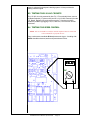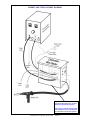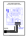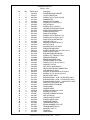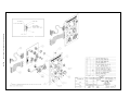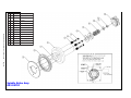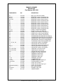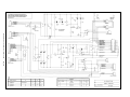
1
Product Description
M.K. Manual Part Number
M.K. Form Number
NWSA Form Number
Effective with Serial Number
Voltage Ratings
Printing/Rev. Date
This manual applies
to the following
Cabinet Model Numbers
Cobramatic
Cabinet
091-0246
CWFIA
550
32135 F92
115 VAC
December 1999 C
150-003
Cobramatic® Wire Feed Cabinet
16882 ARMSTRONG AVE., IRVINE, CALIFORNIA 92606 TEL (949)863-1234 FAX (949)474-1428
SAFETY CONSIDERATIONS
ELECTRIC ARC WELDING EQUIPMENT
CAUTION : READ BEFORE ATTEMPTING INSTALLATION, OPERATION
OR MAINTENANCE OF THIS EQUIPMENT
1-1 INTRODUCTION
This equipment is intended for ultimate
application by commercial/industrial
users and for operation by persons
trained and experienced in the use and
maintenance of welding equipment.
Operation should not be undertaken
without adequate training in the use of
such equipment. Training is available
from many public and private schools or
similar facilities.
Safe practices in the installation,
operation and maintenance of this
equipment requires proper training in the
art, a careful study of the information
provided with the equipment, and the
use of common sense. Rules for safe
use are generally provided by suppliers
of welding power sources, compressed
gas suppliers, and electrode suppliers.
Careful compliance with these rules will
promote safe use of this equipment.
The following Safety Rules cover some
of the more generally found situations.
READ THEM CAREFULLY. In case of
any doubt, obtain qualified help before
proceeding.
1-2 GENERAL PRECAUTIONS
A. Burn Prevention
ELECTRIC ARC WELDING PRODUCES
HIGH INTENSITY HEAT AND
ULTRAVIOLET RADIANT ENERGY
WHICH MAY CAUSE SERIOUS AND
PERMANENT EYE DAMAGE AND WHICH
MAY DAMAGE ANY EXPOSED SKIN
AREAS.
Wear helmet with safety goggles or
glasses with side shields underneath,
appropriate filter lenses or plates
(protected by clear cover glass). This
is a must for welding or cutting (and
chipping) to protect the eyes from radiant
energy and flying metal. Replace cover
glass when broken, pitted, or spattered.
Medical first aid and eye treatment. First
aid facilities and a qualified first aid
person should be available for each shift
unless medical facilities are close by for
immediate treatment of flash burns of
the eyes and skin burns.
Wear protective clothing - leather (or
asbestos) gauntlet gloves, hat, and high
safety-toe shoes. Button shirt collar and
pocket flaps, and wear cuffless trousers
to avoid entry of sparks and slag.
Avoid oily or greasy clothing. A spark
may ignite them.
Flammable hair preparations should not
be used by persons intending to weld or
cut.
Hot metal such as electrode stubs and work
pieces should never be handled without
gloves.
Ear plugs should be worn when working
on overhead or in a confined space. A
hard hat should be worn when others work
overhead.
B. Toxic Fume Prevention
WARNING: The use of this product may
result in exposure to chemicals known to
the State of California to cause cancer and
birth defects or other reproductive harm.
Adequate ventilation. Severe discomfort,
illness or death can result from fumes,
vapors, heat, or oxygen enrichment or
depletion that welding (or cutting) may
produce. Prevent them with adequate
ventilation. NEVER ventilate with oxygen.
Lead-, cadmium-, zinc-, mercury-,
beryllium-bearing and similar materials,
when welded or cut, may produce harmful
concentrations of toxic fumes. Adequate
local exhaust ventilation must be used, or
each person in the area, as well as the
operator, must wear an air-supplied
respirator. For beryllium, both must be used.
Metals coated with or containing materials
that emit toxic fumes should not be heated
unless coating is removed form the work
surface, the area is well ventilated, or the
operator wears an air-supplied respirator.
Work in a confined space only while it is
being ventilated and, if necessary, while
wearing an air-supplied respirator.
Gas leaks in a confined space should be
avoided. Leaked gas in large quantities
can change oxygen concentration
dangerously. Do not bring gas cylinders
into a confined space.
Leaving confined space, shut OFF gas
supply at source to prevent possible
accumulation of gases in the space if
downstream valves have been accidentally
opened or left open. Check to be sure that
the space is safe before reentering it.
Vapors from chlorinated solvents can be
decomposed by the heat of the arc (or
flame) to form PHOSGENE, a highly toxic
gas, and other lung and eye irritating
products. The ultraviolet (radiant) energy
of the arc can also decompose
trichloroethylene and perchloroethylene
vapors to form phosgene. DO NOT WELD
or cut where solvent vapors can be drawn
into the welding or cutting atmosphere or
where the radiant energy can penetrate to
atmospheres containing even minute
amounts of trichloroethylene or
perchloroethylene.
C. Fire and Explosion Prevention
Causes of fire and explosion are:
combustibles reached by the arc, flame,
flying sparks, hot slag, or heated material,
misuse of compressed gases and
cylinders, and short circuits.
BE AWARE THAT flying sparks or falling
slag can pass through cracks, along
pipes, through windows or doors, and
through wall or floor openings, out of
sight of the goggled operator. Sparks
can fly many feet.
To prevent fires and explosion:
Keep equipment clean and operable, free
of oil, grease, and (in electrical parts) of
metallic particles that can cause short
circuits.
If combustibles are in area, do NOT weld
or cut. Move the work if practicable, to
an area free of combustibles. Avoid
paint spray rooms, dip tanks, storage
areas, ventilators. If the work cannot
be moved, move combustibles at least
35 feet away, out of reach of sparks
and heat; or protect against ignition with
suitable and snug-fitting, fire-resistant
covers or shields.
Walls touching combustibles on opposite
sides should not be welded on (or cut).
Walls, ceilings, and floor near work
should be protected by heat-resistant
covers or shields.
Fire watcher must be standing by with
suitable fire extinguishing equipment
during and for some time after welding
or cutting if:
1. Appreciable combustibles (including
building construction) are within 35 feet.
2. Appreciable combustibles are further
than 35 feet, but can be ignited by sparks.
3. Openings (concealed or visible) in
floors or walls within 35 feet may expose
combustibles to sparks.
4. Combustibles adjacent to walls,
ceilings, roofs, or metal partitions can
be ignited by radiant or conducted heat.
Hot work permit should be obtained
before operation to ensure supervisor’s
approval that adequate precautions have
been taken.
After work is done, check that area is
free of sparks, glowing embers, and
flames.
An empty container that held
combustibles, or that can produce
flammable or toxic vapors when heated,
must never be welded on or cut, unless
container has first been cleaned in
accordance with industry standards.
This includes: a thorough steam or
caustic cleaning (or a solvent of water
washing,
depending
on
the
combustible’s solubility), followed by
purging and inerting with nitrogen or
carbon dioxide, and using protective
equipment.
Water-filling just below working level may
substitute for inerting.
A container with unknown contents
should be cleaned (see paragraph
above). Do NOT depend on sense of
smell or sight to determine if it is safe to
weld or cut.
Hollow castings or containers must be
vented before welding or cutting. They
can explode.
Explosive atmospheres. NEVER weld
or cut where the air may contain
flammable dust, gas, or liquid vapors
(such as gasoline).
D. Compressed Gas Equipment
The safe handling of compressed gas
equipment is detailed in numerous
industry publications. The following
general rules cover many of the most
common situations.
1. Pressure Regulators
Regulator relief valve is designed to
protect only the regulator from
overpressure; it is not intended to
protect any downstream equipment.
Provide such protection with one or more
relief devices.
Never connect a regulator to a cylinder
containing gas other than that for which
the regulator was designed.
Remove faulty regulator from service
immediately for repair (first close cylinder
valve). The following symptoms indicate
a faulty regulator:
Leaks - if gas leaks externally.
Excessive Creep - if delivery pressure
continues to rise with downstream valve
closed.
Faulty Gauge - if gauge pointer does not
move off stop pin when pressurized,
nor returns to stop pin after pressure
release.
Repair. Do NOT attempt repair. Send
faulty regulators for repair to
manufacturer’s designated repair center,
where special techniques and tools are
used by trained personnel.
2. Cylinders
Cylinders must be handled carefully to
prevent leaks and damage to their walls,
valves, or safety devices:
Avoid electrical circuit contact with
cylinders including third rails, electrical
wires, or welding circuits. They can
produced short circuit arcs that may lead
to a serious accident. (See 1-3C)
ICC or DOT marking must be on each
cylinder. It is an assurance of safety
when the cylinder is properly handled.
Identifying gas content. Use only
cylinders with name of gas marked on
them; do not rely on color to identify gas
content. Notify supplier if unmarked.
NEVER DEFACE or alter name, number, or
other markings on a cylinder. It is illegal
and hazardous.
Empties: Keep valves closed, replace caps
securely; mark MT; keep them separate
from FULLS, and return promptly.
Prohibited use. Never use a cylinder or its
contents for other than its intended use,
NEVER as a support or roller.
Locate or secure cylinders so they cannot
be knocked over.
Passageways and work areas. Keep
cylinders clear of areas where they may
be stuck.
Transporting cylinders. With a crane, use
a secure support such as a platform or
cradle. Do NOT lift cylinders off the ground
by their valves or caps, or by chains, slings,
or magnets.
Do NOT expose cylinders to excessive
heat, sparks, slag, and flame, etc. that may
cause rupture. Do not allow contents to
exceed 55 degrees C (130 degrees F.) Cool
with water spray where such exposure
exists.
Protect cylinders, particularly valves from
bumps, falls, falling objects, and weather.
Replace caps securely when moving
cylinders.
Stuck valve. Do NOT use a hammer or
wrench to open a cylinder valve that
cannot be opened by hand. Notify your
supplier.
Mixing gases. NEVER try to mix any gases
in a cylinder.
NEVER refill any cylinder.
Cylinder fittings should never be modified
or exchanged.
3. Hose
Prohibited use. Never use hose other than
that designed for the specified gas. A
general hose identification rule is: red for
fuel gas, green for oxygen, and black for
inert gases.
Use ferrules or clamps designed for the
hose (not ordinary wire or other substitute)
as a binding to connect hoses to fittings.
No copper tubing splices. Use only
standard brass fittings to splice hose.
Avoid long runs to prevent kinks and abuse.
Suspend hose off ground to keep it from
being run over, stepped on, or otherwise
damaged.
Coil excess hose to prevent kinks and
tangles.
may clog orifices and damage seats
before connecting regulator. Except for
hydrogen, crack valve momentarily,
pointing outlet away from people and
sources of ignition. Wipe with a clean,
lintless cloth.
Match regulator to cylinder. Before
connecting, check that the regulator label
and cylinder marking agree, and that the
regulator inlet and cylinder outlet match.
NEVER Connect a regulator designed for
a particular gas or gases to a cylinder
containing any other gas.
Tighten connections. When assembling
threaded connections, clean and smooth
seats where necessary. Tighten. If
connection leaks, disassemble, clean,
and retighten, using properly fitting
wrench.
Adapters. Use a CGA adapter (available
from your supplier) between cylinder
and regulator, if one is required. Use
two wrenches to tighten adapter marked
RIGHT and LEFT HAND threads.
Regulator outlet (or hose) connections
may be identified by right hand threads
for oxygen and left hand threads (with
grooved hex on nut or shank) for fuel
gas.
5. Pressurizing Steps:
Drain regulator of residual gas through
suitable vent before opening cylinder (or
manifold valve) by turning adjusting
screw in (clockwise). Draining prevents
excessive compression heat at high
pressure seat by allowing seat to open
on pressurization. Leave adjusting
screw engaged slightly on single-stage
regulators.
Stand to side of regulator while opening
cylinder valve.
Open cylinder valve slowly so that
regulator pressure increases slowly.
When gauge is pressurized (gauge
reaches regulator maximum) leave
cylinder valve in following position: for
oxygen and inert gases, open fully to
seal stem against possible leak; for fuel
gas, open to less than one turn to permit
quick emergency shut-off.
Use pressure charts (available from your
supplier) for safe and efficient
recommended pressure settings on
regulators.
Check for leaks on first pressurization
and regularly thereafter. Brush with
soap solution. Bubbles indicate leaks.
Clean off soapy water after test; dried
soap is combustible.
Protect hose from damage by sharp edges,
and by sparks, slag, and open flame.
E. User Responsibilities
Examine hose regularly for leaks, wear,
and loose connections.
Immerse
pressured hose in water; bubbles indicate
leaks
Remove leaky or defective equipment
from service immediately for repair. Read
and follow user manual instructions.
Repair leaky or worn hose by cutting area
out and splicing. Do NOT use tape.
Close gas supply at source and drain
gas.
4. Proper Connections
Clean cylinder valve outlet of impurities that
G. Rope Staging-Support
Follow all Safety Rules.
F. Leaving Equipment Unattended
Rope staging-support should not be used
for welding or cutting operation; rope
may burn.
1-3 ARC WELDING
Comply with precautions in 1-1, 1-2, and
this section. Arc Welding, properly done,
is a safe process, but a careless
operator invites trouble. The equipment
carries high currents at significant
voltages. The arc is very bright and hot.
Sparks fly, fumes rise, ultraviolet and
infrared energy radiates, weldments are
hot, and compressed gases may be
used. The wise operator avoids
unnecessary risks and protects himself
and others from accidents.
A. Burn Protection
Comply with precautions in 1-2.
The welding arc is intense and visibly
bright. Its radiation can damage eyes,
penetrate lightweight clothing, reflect
from light-colored surfaces, and burn
the skin and eyes. Skin burns resemble
acute sunburn; those from gas-shielded
arcs are more severe and painful. DON’T
GET BURNED; COMPLY WITH
PRECAUTIONS.
welding, a separate room or enclosed bay
is best. In open areas, surround the
operation
with
low-reflective,
noncombustible screens or panels. Allow
for free air circulation, particularly at floor
level.
Viewing the weld. Provide face shields for
all persons who will be looking directly at
the weld.
Others working in area. See that all persons
are wearing flash goggles.
Before starting to weld, make sure that
screen flaps or bay doors are closed.
B. Toxic Fume Prevention
Comply with precautions in 1-2B.
Generator engine exhaust must be vented
to the outside air. Carbon monoxide can
kill.
C. Fire and Explosion Prevention
Comply with precautions in 1-2C.
Equipment’s rated capacity. Do not overload
arc welding equipment. It may overheat
cables and cause a fire.
Loose cable connections may overheat or
flash and cause afire.
connect the equipment ground lead to
the third (live) wire, or the equipment
will become electrically HOT - a
dangerous condition that can shock,
possibly fatally.
Before welding, check ground for
continuity. Be sure conductors are
touching bare metal of equipment frames
at connections.
If a line cord with a ground lead is
provided with the equipment for
connection to a switch box, connect the
ground lead to the grounded switch box.
If a three-prong plug is added for
connection to a grounded mating
receptacle, the ground lead must be
connected to the ground prong only. If
the line cord comes with a three-prong
plug, connect to a grounded mating
receptacle. Never remove the ground
prong from a plug, or use a plug with a
broken ground prong.
2. Connectors
Fully insulated lock-type connectors
should be used to join welding cable
lengths.
3. Cables
Frequently inspect cables for wear,
cracks, and damage. IMMEDIATELY
REPLACE those with excessively worn
or damaged insulation to avoid possibly
lethal shock from bared cable. Cables
with damaged areas may be taped to
give resistance equivalent to original
cable.
1. Protective Clothing
Wear long-sleeve clothing in addition to
gloves, hat, and shoes. As necessary,
use additional protective clothing such
as leather jacket or sleeves, flameproof
apron, and fire-resistant leggings. Avoid
outer garments of untreated cotton.
Never strike an arc on a cylinder or other
pressure vessel. It creates a brittle area
that can cause a violent rupture or lead to
such a rupture later under rough handling.
Bare skin protection. Wear dark,
substantial clothing. Button collar to
protect chest and neck, and button
pockets to prevent entry of sparks.
E. Shock Prevention
Exposed electrically hot conductors or other
bare metal in the welding circuit, or in
ungrounded, electrically-HOT
2. Eye and Head Protection
Protect eyes from exposure to arc. Eyes
may be damaged by radiant energy
when exposed to the electric arc, even
when not looking in the direction of the
arc. Never look at an electric arc without
protection.
equipment can fatally shock a person
whose body becomes a conductor. DO
NOT STAND, SIT, LIE, LEAN ON, OR TOUCH
a wet surface when welding without
suitable protection.
4. Terminals and Other Exposed
Parts
Terminals and other exposed parts of
electrical units should have insulating
covers secured before operation.
To protect against shock:
5. Electrode Wire
Electrode wire becomes electrically HOT
when the power switch of gas metalarc welding equipment is ON and welding
gun trigger is pressed. Keep hands and
body clear of wire and other HOT parts.
Welding helmet or shield containing a filter
plate shade no. 12 or denser must be
used when welding. Place over face
before striking arc.
Protect filter plate with a clear cover
plate.
Cracked or broken helmet or shield should
NOT be worn; radiation can be passed
through to cause burns.
Cracked, broken, or loose filter plates
must be replaced IMMEDIATELY. Replace
clear cover plate when broken, pitted,
or spattered.
Flash goggles with side shields MUST
be worn under the helmet to give some
protection to the eyes should the helmet
not be lowered over the face before an
arc is struck. Looking at an arc
momentarily with unprotected eyes
(particularly a high intensity gas-shielded
arc) can cause a retinal burn that may
leave a permanent dark area in the field
of vision.
3. Protection of Nearby Personnel
Enclose the welding area. For production
D. Compressed Gas Equipment
Comply with precautions in 1-2D.
Keep body and clothing dry. Never work in
damp area without adequate insulation
against electrical shock. Stay on a dry
duckboard, or rubber mat when dampness
or sweat cannot be avoided. Sweat, sea
water, or moisture between body and an
electrically HOT part - or grounded metal reduces the body surface electrical
resistance, enabling dangerous and
possibly lethal currents to flow through the
body.
1. Grounding the Equipment
When installing, connect the frames of each
unit such as welding power source,
control, work table, and water circulator to
the building ground. Conductors must be
adequate to carry ground currents safely.
Equipment made electrically HOT by stray
currents may shock, possibly fatally. Do
NOT GROUND to electrical conduit, or to a
pipe carrying ANY gas or a flammable liquid
such as oil or fuel.
Three-phase connection. Check phase
requirement of equipment before installing.
If only three-phase power is available,
connect single-phase equipment to only
two wires of the three-phase line. Do NOT
Keep cable dry, free of oil and grease,
and protected from hot metal and sparks.
6. Safety Devices
Safety devices such as interlocks and
circuit breakers should not be
disconnected or shunted out.
Before installation, inspection, or service
of equipment, shut OFF all power, and
remove line fuses (or lock or red-tag
switches) to prevent accidental turning
ON of power. Disconnect all cables from
welding power source, and pull all 115
volts line-cord plugs.
Do not open power circuit or change
polarity while welding. If, in an
emergency, it must be disconnected,
guard against shock burns or flash from
switch arcing.
Leaving equipment unattended. Always
shut OFF, and disconnect all power to
equipment.
Power disconnect switch must be
available near the welding power
source.
This page intentionally blank
Cobramatic Owner's Manual P/N 091-0246 - Page 5
Table Of Contents
Introduction ........................................................................................ 8
Section
Section
Section
Section
Section
1
2
3
4
5
Specifications ..............................................................
Support Equipment Required .....................................
Coolant Recommendations .........................................
Optional Accessories ...................................................
Installation .................................................................
5.1
5.2
5.3
5.4
Section 6
9
9
9
9
10
Location ............................................................................................. 10
Contactor Selection ............................................................................. 10
115 VAC Connections .......................................................................... 10
Posa Start Connections ........................................................................ 10
Wire Threading Procedure ......................................... 10
6.1
6.2
6.3
6.4
Section 7
Wire Spool Installation ......................................................................... 10
Threading Procedure ........................................................................... 10
Pre-Setting Slave Motor Tension ........................................................... 11
Wire Guard ........................................................................................ 11
Operation .................................................................... 12
7.1
7.2
7.3
Section 8
General .............................................................................................. 12
Feeder Controls .................................................................................. 12
CV/CC Posa Start Operating Procedure ................................................. 12
Maintenance ............................................................... 14
8.1
8.2
8.3
8.4
Testing The Torch ............................................................................... 14
Relay K2 Operations ............................................................................ 14
Testing the 115 VAC Circuits ................................................................ 15
Testing the Speed Control .................................................................... 15
Trouble Shooting ................................................................................ 16
Cabinet and Torch Hook-up Diagram ..................................................... 17
Input Power Connections ..................................................................... 18
Posa Start and Contactor Connections ................................................... 19
Drawings ............................................................................................ 20
Main PC Board Connections .................................................................. 25
Main PC Board Parts Placement ............................................................ 26
Main PC Board Parts List ...................................................................... 27
Front Panel Circuit Board ..................................................................... 28
Schematics ........................................................................................ 29
This page intentionally blank
Cobramatic Owner's Manual P/N 091-0246 - Page 7
INTRODUCTION
Thank you for purchasing what we believe is the best built wire feeder on the
market. This manual details the installation of your Cobramatic Cabinet.
Properly installed, adjusted, and maintained for your welding conditions, it will
prove to be a reliable welding system producing consistently uniform welds.
The Cobramatic can be used with any Constant Voltage(CV) or Constant
Current(CC) type power source. CV-CC Posa Start "Run-in Speed" is included
as a standard feature.
The Cobramatic has a 7 pin "W" clocked amphenol torch connector for easy
hook-up to the complete line of MK Products 7 pin "W" clocked amphenol
torches. The 7 pin "S" torches may also be connected by using an "S"
clocked amphenol adaptor kit
(P/N 005-3563).
In order to assure optimum performance of your Cobramatic equipment,
familiarize yourself with the contents of this manual, and carefully follow all
instructions.
This manual will not only guide you in installing your Cobramatic equipment,
but will also be a handy reference for optional items, replacement parts, and
consumables.
Cobramatic Owner's Manual P/N 091-0246
- Page 8
Section 1
SPECIFICATIONS
Wire Diameter Capacity ................................... .030 - 1/16" ALL Types
Wire Capacity ................................................... 12" Standard (Insulated or
............................................................................ Non-Insulated)
Power Input ....................................................... 115 VAC 50/60 Hz,
............................................................................ 150 Watts Peak (1.3 amps)
Weight ................................................................ 31 pounds
Shipping Weight ............................................... 36 pounds
For Use with Torch Prefix Numbers ................ 145, 146, 147, 148, 149,
162, 163, 210, 211, 212, 213, 216 (and 109, 156, 118, 133, 160, 161 when kit
p/n 005-3563 is installed).
Section 2
SUPPORT EQUIPMENT REQUIRED
C. V. or C.C. Power Source of Sufficient Capacity for Your Needs.
Regulated Gas Supply and Hoses.
Properly Sized Power Leads from Power Source to Wire Feeder and Ground.
Water Source and Hose Capable of Providing a Minimum of 1 qt/min. at 45
p.s.i. when using water cooled torches.
Section 3
COOLANT RECOMMENDATIONS
1. Use a name-brand additive which does not contain reactive sulphur or
chlorine and does not react with copper, brass, or aluminum.
2. Check coolant periodically to remain within limits of the following:
A.
B.
C.
D.
Section 4
Coolant Flow rate - 1 quart/minute at 45 p.s.i.
Resistivity - 10K ohms/centimeter
Ph Range - 5.5-8.5
Particle Size - .005"
OPTIONAL ACCESSORIES
Plastic Guides for Slave Motor
Inlet Guide
Outlet Guide with Knob
753-0062
003-0428
Optional Kits
Cabinet Pot Kit
"S" Clocked Sup. Kit
Pre-set Adj. Screw
Water Flow Kit
Wire Guard Kit
005-0615
005-3563
005-0125
005-0253
005-0618*
*Standard on all Wire Feeders
Cobramatic Owner's Manual P/N 091-0246 - Page 9
Section 5
INSTALLATION
5.1 LOCATION
The cabinet should be placed in a location where it can be protected from
damage. Lead lengths and accessibility to a 115 VAC 50/60 Hz outlet must
also be considered when installing the cabinet.
5.2 CONTACTOR SELECTION
The Cobramatic is shipped from the factory in the closing contacts position.
A eight foot (8') contactor cable is supplied with the unit to which the black
and white wires supply the contactor signal.
NOTE: REFER TO THE POWER SUPPLY OWNER’S MANUAL FOR LOCATION
AND TYPE OF CONTACTOR SIGNAL REQUIRED.
WARNING: Disconnect the Cobramatic Cabinet from all power sources
before changing contactor.
If a 115 VAC signal is required, remove the screws from the left side of the
cabinet and lift up the cover door. Locate the white and black wire on J6-3
and J6-4. Move the black wire from J6-4 to J5-4 and white wire from J6-3 to
J5-3. The unit will now supply 115 VAC on the black (hot) and white (neutral)
wires.
5.3 115 VAC CONNECTIONS
Connect the supplied 8' three (3) prong plug to a 115 VAC 50/60 Hz outlet.
The 115 VAC cord is connected to the PC Board on terminal strip J5 #1
(neutral) and #2 (hot) and Ground to the Cabinet chassis.
5.4 POSA START CONNECTIONS
Attach the No. 14 single black lead which extends from the back of the
Cobramatic I to the negative terminal of the welding power source or work
ground. The Posa Start lead is internally connected to the P.C. board on
terminal strip J6 terminal 2.
Section 6
WIRE THREADING PROCEDURE
6.1 WIRE SPOOL INSTALLATION
Release latches, and open right side door of cabinet.
Remove spool retainer from spindle hub.
Install wire spool onto spindle hub so that wire feeds from bottom of spool
towards slave motor. Make sure that the hole in the spool aligns with pin on
spindle hub. The white dot on the end of the spindle hub will aid in this
alignment.
Replace the spool retainer.
6.2 THREADING PROCEDURE
Cobramatic Owner's Manual P/N 091-0246
- Page 10
Place wire size selector switch on front panel to the correct position for the
wire being used.
Loosen end of wire from spool and cut off any kinked or bent portions.
Unreel and straighten out first 6" to 8" of wire.
Release tension from slave motor drive rolls.
Route wire into inlet guide, along drive roll groove, and into wire conduit.
Prevent the wire spool from turning with the palm of the right hand, and at the
same time grasp the slave motor pressure adjusting knob.
Pull the torch trigger and slowly tighten the slave motor pressure adjusting
knob until the slave motor stalls.
CAUTION:
EXCESSIVE DRIVE ROLL TENSION WILL REDUCE RATHER
THAN IMPROVE WIRE FEED PERFORMANCE.
Tighten the torch pressure adjusting knob so the wire will be picked up and
fed through the contact tip. Proper tension is achieved when wire does not
slip if a small amount of pressure is added to the wire as it exits the tip.
6.3 PRE-SETTING SLAVE MOTOR TENSION
(Read Sections 6.1 & 6.2 before performing this operation.)
All Cobramatics have preset adjusting nuts which enables spools of the same
wire diameter and type to be changed without further pressure adjustment
after initial
set-up.
To preset the slave motor tension bottom out the pressure adjusting knob by
turning it completely clockwise.
Prevent the wire spool from turning and using a 9/16" wrench adjust the preset
nut until the slave motor stalls.
Correct pressure will now be achieved by simply bottoming out the pressure
adjusting knob.
6.4 WIRE GUARD
The Cobramatic® Wire Guard is designed to keep the welding wire from
jumping off the spool inside the wire feed cabinet. When the trigger is
released and the brake engages, especially when using a new spool that is
heavier towards the outside, the spool will tend to rotate more against the
spindle drag adjustment.
However since the wire is held by the slave motor it will not move and could
subsequently jump off the back of the spool and become lodged in the brake
mechanism, or jump off the front of the spool and electrically short-out to the
cabinet chassis. The wire guard will keep the wire from doing either.
The wire guard is designed to run inside the spool on top of the wire, and
when the brake is engaged the wire guard will hold the wire onto the spool.
The wire guard is made of a heavy woven nylon material that is resistant to
wear and will not contaminate the surface of the wire.
Cobramatic Owner's Manual P/N 091-0246 - Page 11
Section 7
OPERATION
7.1 GENERAL
The Cobramatic is an up-dated version of the popular Cobramatic Cabinet and
operates on the same basic principles. The 115 VAC slave motor in the
feeder runs at a fast, constant speed, but has very low torque. It is always
trying to feed more wire than the torch motor wants, and when the motor gets
all it wants, it slows the slave motor preventing a bird’s nest. Because of the
low torque produced by the slave motor, a brake system is used to prevent
wire overrun rather than tension. The drag adjustment in the spindle is used
to keep the wire slightly taut, so it will not unspool while feeding wire. The 24
VDC torch pull motor is controlled by a solid state speed control and a
potentiometer located in the torch.
7.2 FEEDER CONTROLS
7.2.1. ON/OFF SWITCH
Placing the switch in the “ON” position energizes the feeder circuitry and the
power indicator light.
7.2.2. WIRE SIZE SELECTOR SWITCH
The wire size selector switch changes the torque of the slave motor for the
wire you are using. When in the .030-.035 Aluminum Only position, the
slave motor produces approximately 1 1/2 lb-inches of torque and
approximately 4 1/2 lb-inches of torque when in the All Other Wires position.
(NOTE: Operating the cabinet with the switch in the wrong position
will cause wire feed difficulties.)
7.2.3. POSA START CONTROLS
The Posa Start Control selects a Run-in Speed which is slower than the
welding speed. After arc initiation, the wire feed speed is controlled by the
potentiometer in the gun.
The scale surrounding the Run-in Speed Control is a relative scale only; it
does not represent actual inches per minute.
7.2.4. TORCH AMPHENOL CONNECTORS
The Cobramatic contains a 7 pin “W” clocked amphenol. For "S" clocked
torches order kit p/n 005-3563. See specifications for torch compatibility.
7.2.5. CONDUIT INLET
The Conduit Inlet provides access to the slave motor outlet guide.
7.2.6. GAS INLET
Provides access to the gas fitting inside the cabinet.
7.2.7. POWER INLET
The Power Inlet provides access to the power block inside the cabinet.
7.3 CV/CC POSA START OPERATING PROCEDURE
7.3.1. GENERAL
The Posa Start feature allows the Cobramatic to be used in combination with
constant current DC welding power sources of open circuit voltage in excess
of 55 volts - also, any constant voltage welding power source capable of a
minimum of 50 amps.
Cobramatic Owner's Manual P/N 091-0246
- Page 12
(NOTE: Reverse polarity MUST be used.)
CAUTION:
DO NOT OPERATE A COBRAMATIC ON A POWER SOURCE HAVING A HIGHFREQUENCY STARTING CIRCUIT BEFORE MAKING SURE THAT THE HIGHFREQUENCY PORTION OF THE POWER SOURCE IS TURNED OFF. FAILURE TO
TAKE THIS PRECAUTION WILL CAUSE PERMANENT DAMAGE TO THE POSA START
CIRCUITRY.
The Posa Start Run-in Speed Control, located on the front panel, provides
adjustment for slow wire run-in. Once the arc has been established, the wire
feed speed is automatically changed from the slow run-in speed to the welding
speed set on the torch potentiometer.
7.3.2. CV POSA START OPERATION
Attach Cobramatic to CV power source according to the installation
instructions.
Turn the Cobramatic to the “ON” position and the Posa Start to the “OFF”
position.
Adjust power source to desired voltage for your weld condition.
Depress gun trigger and adjust wire feed speed at gun to match voltage
setting. If approximate wire feed is not known, it is better to start with excess
wire feed rather than too little, in order to prevent a “burn-back”.
Turn the Posa Start switch to the “ON” position. Press torch trigger and,
using Run-in Speed Control, adjust wire feed rate to approximately 10% of the
welding wire speed.
Strike an arc, and adjust wire feed rate at gun until correct condition is
achieved.
7.3.3. CC POSA START OPERATION
Attach the Cobramatic to a CC power source according to the installation
instructions.
Insure power supply high frequency switch is in the “OFF” position, and
power supply is set to DC reverse polarity.
The power supply contactor should be set to “Remote” or “Tig” and the
amperage control set to “Panel” or “Standard” depending on power supply.
Turn the Cobramatic power switch to the “ON” position and the Posa Start
switch to the “OFF” position.
Adjust power source to desired amperage for your weld condition.
Press gun trigger and adjust wire feed speed at gun to match current setting.
If approximate wire feed speed is not known, it is better to start with excess
wire feed rather than too little, in order to prevent possible damage to the
contact tip.
Turn Posa Start switch to the “ON” position. Press torch trigger and, using
Run-in Speed Control, adjust wire feed speed to approximately 10% of the
welding wire speed.
Strike an arc; if the wire stubs out, reduce wire feed rate at gun, or increase
amperage setting on power source.
Cobramatic Owner's Manual P/N 091-0246 - Page 13
NOTE: Because the Posa Start Run-in Speed always remains a percentage of the
actual welding wire feed rate, the Posa Start run-in speed will always slow down
or speed up proportional to any adjustment you now make at the gun. Therefore, if
you slow down the welding wire feed speed, you will have to increase the Run-in
Speed setting.
Section 8
MAINTENANCE
Maintenance of the torch will normally consist of a general cleaning of the wire
guide system, including tubes, drive rolls, and conduits at regular intervals.
Remove spatter build-up from inside of nozzles with a hardwood stick.
The only parts on the Cobramatic system that are subject to normal wear are
the conduit, contact tips, gas cups, front body liners, wire guides, drive and
idler rolls. A supply of these parts should be maintained on hand.
If repairs do become necessary, any part can easily be replaced by a qualified
shop maintenance person.
Your Cobramatic is designed to provide years of reliable service. Normal wear
and component failure may require occasional service.
The number of units in operation and the importance of minimal "down time"
will determine to what extent spare parts should be stocked on hand.
8.1 TESTING THE TORCH
8.1.1. MOTOR CHECK
a. Remove the amphenol connector from the cabinet.
b. Using the torch amphenol, check the resistance across pins “A” and
“B”(motor
leads). The resistance across the motor should be between
5-10 ohms.
c. If an open circuit or short exist, check the motor leads and motor
independently.
8.1.2. TESTING THE POTENTIOMETER - “W” CLOCKED
a. Using the torch amphenol, check the resistance across pin “D” (wiper)
and pin “C”. The resistance should vary from 0 - 5K ohms.
b. Check the resistance across pin “D” (wiper) and pin “G”. The resistance
should vary from 5K - 0 ohms.
8.1.3. TESTING THE POTENTIOMETER - “S” CLOCKED
a. Using the torch amphenol, check the resistance across pin “D” (wiper)
and pin “C”. The resistance should vary from 0 - 5K ohms.
b. Check the resistance across pin “D” (wiper) and pin “A”. The resistance
should vary from 5K -0 ohms.
8.1.4. TESTING THE MICRO SWITCH
a. Using the torch amphenol, check for continuity across pins “E” and “F”
when the trigger is pressed.
8.2 RELAY K2 OPERATION
When the torch trigger is pressed, 24VAC is sent to the coil of relay K2.
When K2 is energized, 115VAC is sent to the slave motor, spool brake, and
the 115VAC contactor. Relay K2 is also responsible for sending 24VAC to the
speed control circuit and shorting the torch motor leads together when the
Cobramatic Owner's Manual P/N 091-0246
- Page 14
trigger is released for the dynamic braking system. K2 also provides the
closing contactor signal.
8.3 TESTING THE 115 VAC CIRCUITS
The 115 VAC circuit is protected by fuse F3. If F3 continually blows, remove
J4 (Brake Solenoid), J7 (slave motor) and J5-3,4 (115 VAC Contactor) from the
P.C. Board. Replace fuse, and retrigger system. If fuse does not blow;
isolate the problem by plugging in J4, J7, and J5-3,4 one at a time until the
fuse blows.
8.4 TESTING THE SPEED CONTROL
NOTE: The torch should be tested first and the amphenol must be connected
to the Cobramatic to perform this test.
Place a voltmeter across diode D10 and press torch trigger. A reading of 0 24VDC should be observed, as the torch potentiometer varies.
24.0
D10
VDC
+
Cobramatic Owner's Manual P/N 091-0246 - Page 15
_
TROUBLESHOOTING
TROUBLE
CAUSE
No wire feed at torch, feeder not
operating, i.e., no slave motor or
brake soleniod.
REMEDY
F3 (2 amp) fuse in feeder blown.
Check AC circuit. Replace fuse
F1 (4 amp) fuse in feeder blown.
Check motor leads for shorts, then
replace fuse
Micro-switch defective/not being
activated. Broken electrical cable.
Replace switch. Check switch for
operation. Check micro switch
wires for continuity.
Relay K2 inoperative.
Check/Replace relay K2.
Loose J2, J3, P.C. board connector
Check J2, J3 connectors.
Brake soleniod inoperative.
Soleniod defective.
Replace soleniod.
Relay K2 inoperative.
Check for 115VAC across J4-1 and
J4-2
Check relay K2 for AC not present.
No wire feed at torch, feeder
operating properly.
Wire feeds, but welding wire is not
energized.
Bad potentiometer.
Check potentiometer with meter.
Bad torch motor.
Check/Replace motor.
Broken electrical cable.
Check motor and potentiometer
wires for continuity.
Bad speed control/PCB.
Check/Replace P.C. Board.
Loose or no cable connections.
Check all power connections.
Relay K2 not sending contactor
signal.
Check/Replace relay K2.
Contactor control cable loose or in
wrong position.
Check power supply owners
manual for location and type of
contactor signal required, i.e.
closing contacts or AC.
Welding power source not working Check power supply for proper
right.
operation.
Wire feeds erratically.
Wire feeds one speed only
Wire walks out of drive rolls
Excessive spool drag pressure.
Decrease spool drag pressure
inside hub.
Dirty or worn conduit.
Blow out or replace conduit.
Incorrect pressure on drive rolls.
Adjust pressure at both feeder and
torch.
Idler roll stuck.
Check for lock washer under idler
roll, or replace if damaged or worn.
Wrong size contact tip.
See contact tip table.
Bad potentiometer.
Check with meter.
Broken electrical cable in lead
assy.
Check potentiometer wires for
continuity or shorts.
Bad speed control.
Check/Replace P.C. Board.
Idler roll upside-down.
Place groove in idler roll towards
top.
Rear wire guide missing.
Replace wire guide.
Cobramatic Owner's Manual P/N 091-0246 - Page 16
CABINET AND TORCH HOOKUP DIAGRAM
Input Power Cable must be
connected to bottom hole or PosaStart will not operate properly!
Upper hole is to be used only when
connecting the Prince spoolgun to
the cabinet as a push-pull system.
Cobramatic Owner's Manual P/N 091-0246 - Page 17
INPUT POWER CONNECTIONS
(only apply rated voltage for cabinet)
J5
Do not put input
power here.
INPUT POWER
CONNECTIONS
GREEN WIRE
WHITE WIRE
BLACK WIRE
Cobramatic Owner's Manual P/N 091-0246 - Page 18
POSA START & CONTACTOR
CONNECTIONS
J6
J5
115 VAC
CONTACTOR
OUTPUT
BLACK WIRE
Choose
Position
POSA START
WORK GROUND
CONNECTION
WHITE WIRE
CLOSING CONTACTS
CONTACTOR OUTPUT
BLACK WIRE
WHITE WIRE
Cobramatic Owner's Manual P/N 091-0246 - Page 19
Cobramatic Owner's Manual P/N 091-0246 - Page 20
Cobramatic Parts List
P/N 001-1132
No.
1
2
3
4
5
6
7
8
9
10
11
12
13
14
15
16
17
18
19
20
21
22
23
24
25
26
27
28
29
30
31
32
33
34
35
36
37
38
39
40
41
42
43
44
45
46
47
48
49
50
51
52
53
54
55
Qty.
1
1
14
4
12
4
4
2
2
1
1
1
3
2
1
2
2
2
1
1
1
1
1
1
1
1
1
12
3
2
1
1
6
4
1
1
1
4
1
1
1
1
4
4
4
4
1
1
1
4
1
4
2
4
1
Part Number
436-0035
438-0017
336-0038
301-0103
333-0043
336-0006
341-0005
329-0003
332-0009
261-0105
003-1674
261-0104
336-0037
329-0005
261-0372
331-0005
333-0009
341-0010
003-2014
003-0570
328-0112
003-0784
351-0758
327-0012
419-0080
003-2096
003-0773
336-0005
331-0002
345-0008
405-0724
003-1628
342-0410
336-0039
003-1673
351-0752
351-0744
351-0745
351-0082
411-0157
003-1698
415-0243
329-0219
331-0067
333-0007
341-0007
843-0064
003-0796
843-0327
351-0086
405-0757
351-0089
331-0049
411-0020
301-0087
Description
SCREENED BASE CABINET
COVER, FRONT PCB
SCREW, PH FIL T/B #6-32 X 3/8
RUBBER FEET
WASHER, INT-STAR #6
SCREW, PH.FIL #6-32 X 1/2
NUT, HEX #6-32
SCREW, HEX 1/4-20 X 3/4
WASHER, SHOULDER 0.265 ID
INSULATOR POWER BLOCK
POWER BLOCK ASSY
INSULATOR, SPOOL
SCREW, PH FIL TB #6-32 X 1/4
SCREW, HEX 1/4-20 X 1.00 LG
INSULATOR, SLAVE MOTOR
WASHER, FLAT 1/4
WASHER, SPRING LOCK 1/4
NUT, HEX 1/4-20
SLAVE MOTOR 115V ASSY.
SPINDLE BRAKE ASSY.
SCREW, SOCKET HD. 3/8-16 X 1.00 LG.
PAWL RATCHET ASSY.
BUSHING SNAP Ø3/4 BLACK
SCREW, ST T/F #6-32 X 1/4 LG.
SPRING EXTENSION
BRAKE SOLENOID ASSY.
TRANSFORMER 115V ASSY.
SCREW, PH.FIL. #6-32 X 3/8 LG.
WASHER, FLAT #6
NUT, SELF-LOCKING #6-32
DECAL, ELECTRONIC CONNECTION
PCB, MAIN 115V ASSY.
SPACER, STACKING #6-32 X 0.534 LG.
SCREW, PH. FIL. #10-32 X 3/8 LG.
FRONT PANEL ASSY.
BUSHING SNAP 1.12 ID, 1.50 DIA MTG. HOLE
BUSHING SNAP 1.00 ID, 1.375 DIA MTG. HOLE
BUSHING SNAP 15/16 ID, 1.125 DIA MTG. HOLE
CAP PLUG 7/8 DIA MTG. HOLE
CLAMP CABLE STRAIN REL
DOORS ASSY.
HANDLE CARRY
SCREW, HEX #10-24 X 1/2 LG.
WASHER, FLAT #10
WASHER, SPRING LOCK #10
NUT, HEX #10-24
CABLE CONTACTOR 8 FT
POWER CABLE ASSY.
POSASTART CABLE
THREAD INSERT #6-32
SERIAL NUMBER I.D. PLATE
THREAD INSERT #10-32
WASHER, FLAT 1/4
TIE WRAP
WIRE GUARD
Cobramatic Owner's Manual P/N 091-0246 - Page 21
Cobramatic Owner's Manual P/N 091-0246 - Page 22
No.
Qty.
Part No.
Description
1
1
003-0569
Bearing Assy
2
1
437-0645
Spindle, Molded
3
1
723-0059
Disk Brake
Cobramatic Owner's Manual P/N 091-0246 - Page 23
4
1
431-1266
Back-up Ring
5
3
419-0059
Compression Spring
6
3
331-0063
Washer, Flat
7
3
330-3063
Shoulder Scr 1/4 x 5/8 Mod.
8
1
437-0180
Washer, Modified
9
1
419-0230
Compression Spring
10
1
331-0100
Washer, Flat 5/16
11
1
345-0018
Nut, Self Locking
12
1
431-0169
Spool Retainer
13
1
331-0200
Washer Flat 1-3/8x7/8x 1/32
TB-0570.tbl
Spindle Brake Assy.
003-0570F
No .
P ar t N o .
D es c r i p t i o n
1
003-2017
Assy torque motor 115V
2
507-0128
Hel gear 10T
3
421-0128
Pin, Spring, 1/16 x 3/8 LG
5
001-3092
Assy, gear box, slave motor
6
261-0213
Insulator, gear box
7
431-0347
Casting, gear reduction
8
501-0118
Shaft, bearing reduction
4
Cobramatic Owner's Manual P/N 091-0246 - Page 24
9
507-0130
Shaft, gear
10
501-0156
Bearing, cap
11
431-0334
C ap
Spacer, 1/4 x 0.171 ID
12
342-0063
13
333-0006
Washer, lock, spring, #8
14
328-0026
Screw, socket hd #8-32 x 5/8
15
328-0029
Screw, socket hd #8-32 x 1.00
16
511-0206
Drive roll, slave motor
17
321-0060
Screw, set, #10-24
18
753-0265
Guide, outlet
20
753-0210
Guide, wire Ø1/2
21
328-0024
Screw, socket hd, #8-32 x 3/8
22
431-1082
Nut, stop shaft
23
413-0209
Arm, idler roll
24
331-0050
Washer, Ø1/4
25
419-0211
Spring, comp, 0.62 OD x 0.062
26
345-0047
Nut, adjust
27
003-0273
Knob, pressure shaft
28
331-0044
Washer, flat #10
29
333-0009
Washer, lock, spring Ø1/4
30
501-0207
Idler roll, slave motor
19
Assy Slave Motor
115V
3.4:1 ratio
003-2014A
31
330-0001
Screw, shoulder, 1/4 x 3/8
32
330-0004
Screw, shoulder, 1/4 x 3/4
33
333-0064
Washer, c'sink, int star, Ø1/4
34
324-0286
Screw, flat hd, #1/4-20 x 3/4
MAIN P.C. BOARD CONNECTIONS
Note: For Cabinet Remote Pot Kit, Remove
Jumper from J13-J14.
Plug Remote Pot Kit into
J14.
J14 J13
CURRENT SENSOR
(Posa Start)
J1
J2
J8
J6
J7
J5
FRONT PANEL
J3
FRONT PANEL
J4
BRAKE SOLENOID
SLAVE MOTOR
TRANSFORMER
115VAC CONTACTOR OUT
115VAC CONTACTOR OUT
INPUT CONNECTIONS
INPUT CONNECTIONS
GROUND
CLOSING CONTACTS OUT
CLOSING CONTACTS OUT
WELD CONNECTION (-)
NO CONNECTION
Cobramatic Owner's Manual P/N 091-0246 - Page 25
MAIN P.C. BOARD
PARTS PLACEMENT
Part Number 003-1628
Jumper
J14 J13
COMPONENTS TO BE REPLACED BY QUALIFIED SERVICE PERSONNEL ONLY.
Cobramatic Owner's Manual P/N 091-0246 - Page 26
MAIN P.C. BOARD
PARTS LIST
Part Number 003-1628
COMPONENT #
P/N
K1 ................................. 157-0144
R2, R3 .......................... 115-0154
R4, R5 .......................... 115-0042
R12, R13 ....................... 115-0120
R1 ................................. 115-0274
R6 ................................. 115-0122
R7 ................................. 115-0144
R8 ................................. 115-0138
R9 ................................. 115-0129
R10 ............................... 115-0136
R11 ............................... 115-0141
D1, D3 .......................... 124-0002
D6-D10 .......................... 124-0003
D2 ................................. 124-0010
D4 ................................. 124-0011
D5 ................................. 124-0012
Q1 ................................. 122-0005
Q2 ................................. 122-0011
Q3 ................................. 122-0004
Q4 ................................. 122-0013
Q5 ................................. 125-0028
C1, C5, C8, C9 .............. 101-0016
C2 ................................. 101-0013
C3 ................................. 104-0060
C4, C6 .......................... 104-0002
C7 ................................. 101-0021
RV1, RV5, RV6 ............. 124-0026
RV2, RV3, RV4 ............. 124-0028
C10 ............................... 101-0116
J1 .................................. 153-0866
J2 .................................. 153-0876
J3 .................................. 153-0842
J4 .................................. 153-0844
J5, J6 ............................ 186-0057
J7, J8 ............................ 153-0850
J13, J14 ........................ 153-0867
Fuse Holder .................. 152-0008
F3 ................................. 151-0001
F1 ................................. 151-0043
F2 (220 VAC ONLY) ...... 151-0001
K2 ................................. 157-0022
K2 Socket ..................... 173-0026
Jumper .......................... 003-1307
DESCRIPTION
...................... RELAY, 5V 500 Ohm 200MA
...................... RESISTOR, carbon .25 watt 6.8K ohm
...................... RESISTOR, carbon .50 watt 6.8K ohm
...................... RESISTOR, carbon .25 watt 100 ohm
...................... RESISTOR, carbon .25 watt 4.3K ohm
...................... RESISTOR, carbon .25 watt 150 ohm
...................... RESISTOR, carbon .25 watt 10K ohm
...................... RESISTOR, carbon .25 watt 3.3K ohm
...................... RESISTOR, carbon .25 watt 560 ohm
...................... RESISTOR, carbon .25 watt 2.2K ohm
...................... RESISTOR, carbon .25 watt 5.6K ohm
...................... DIODE, 1 amp 800 volts (IN4006)
...................... DIODE, 2.5 amps 1KV (HEP170)
...................... DIODE, zener 1 watt 4.3 volts (IN4731)
...................... DIODE, zener 1 watt 10 volts (IN4740)
...................... DIODE, zener 1 watt 6.8 volts (IN4736)
...................... TRANSISTOR, NPN 250MA 80 volts (2N4410)
...................... TRANSISTOR, NPN 500MA 250 volts (2N5655)
...................... TRANSISTOR, PNP 1 amp 50 volts (2N4249)
...................... TRANSISTOR, unijunction 30 volts (2N2646)
...................... THYRISTOR, 8 amps 400 volts (MCR218-6)
...................... CAPACITOR, ceramic .01uf 600VDC
...................... CAPACITOR, Poly .047uf 200VDC
...................... CAPACITOR, electrolytic 6.8uf 63 VDC
...................... CAPACITOR, tantalum 10uf 20VDC
...................... CAPACITOR, ceramic .047uf 50VDC
...................... VARISTOR, 130 volts 10 amps
...................... VARISTOR, 56 volts 8 amps
...................... CAPACITOR, poly 3.3uf 250VAC
...................... CONNECTOR, R/A header 2 pin
...................... TERMINAL, header 26 pin
...................... TERMINAL, header 10 pin
...................... TERMINAL, header 2 pin
...................... TERMINAL, strip 4 pin
...................... CONNECTOR, 6 pin
...................... CONNECTOR, R/A header 3 pin
...................... FUSE HOLDER, PC mount
...................... FUSE, AGC 2A 250V
...................... FUSE, 3AG 4A 250V FAST ACT
...................... FUSE, AGC 2A 250V
...................... RELAY, 24VAC 4PDT
...................... SOCKET, relay 15 pin
...................... JUMPER CABLE
Cobramatic Owner's Manual P/N 091-0246 - Page 27
FRONT PANEL CIRCUIT BOARD
Part Number 003-2024
COMPONENT #
P/N
R1 ................................. 113-0593
R2 ................................. 119-0020
R3 ................................. 115-0037
D1 ................................. 124-0045
SW1 ............................. 159-3587
SW2 ............................. 159-3586
SW3 ............................. 159-3586
J1 .................................. 153-0842
J2 .................................. 153-0876
J3 .................................. 153-0860
J4 .................................. 153-0860
DESCRIPTION
...................... RESISTOR, wire wound 400 ohm, 5 watt
...................... POTENTIOMETER, 100K ohm
...................... RESISTOR, carbon 2.7K ohm, 1/2 watt
...................... LED, green
...................... SWITCH, DPDT, p.c. mount
...................... SWITCH, SPDT, p.c. mount
...................... SWITCH, SPDT p.c. mount
...................... HEADER, 10pin, 90 degree
...................... HEADER, 26pin, 90 degree
...................... HEADER, 8pin, 90 degree
...................... HEADER, 8pin, 90 degree
COMPONETS TO BE REPLACED BY QUALIFIED SERVICE PERSONNEL ONLY.
Cobramatic Owner's Manual P/N 091-0246 - Page 28
Cobramatic Owner's Manual P/N 091-0246 - Page 29
Cobramatic Owner's Manual P/N 091-0246 - Page 30
THIS PAGE INTENTIONALLY BLANK
Cobramatic Owner's Manual P/N 091-0246 - Page 31
Effective April 1, 1998
This warranty supersedes all previous MK Products warranties and is
exclusive, with no other guarantees or warranties expressed or implied.
LIMITED WARRANTY - MK Products,Inc.,Irvine,California
warrants that all new and unused equipment furnished by MK
Products is free from defect in workmanship and material as
of the time and place of delivery by MK Products. No warranty
is made by MK Products with respect to trade accessories or
other items manufactured by others. Such trade accessories
and other items are sold subject to the warranties of their
respective manufacturers, if any.
MK Products’ warranty does not apply to components having
normal useful life of less than one (1) year, such as relay points,
wire conduit, tungsten, and welding torch parts that come in
contact with the welding wire, including nozzles, nozzle
insulators, and contact tips where failure does not result from
defect in workmanship or material.
In the case of MK Products’ breach of warranty or any other
duty with respect to the quality of any goods, the exclusive
remedies therefore shall be at MK Products’ option: (1) repair;
(2) replacement; (3) where authorized in writing by MK
Products, the reasonable cost of repair or replacement at our
Irvine, California plant; or (4) payment of or credit for the
purchase price (less reasonable depreciation based upon
actual use) upon return of the goods at customer’s risk and
expense. Upon receipt of notice of apparent defect or failure,
MK Products shall instruct the claimant on the warranty claim
procedures to be followed.
As a matter of general policy only, MK Products may honor an
original user’s warranty claims on warranted equipment in the
event of failure resulting from a defect within the following
periods from the date of delivery of equipment to the original
user:
1. Torches and Weldheads ........................ 1 year
2. All Other Equipment ............................... 3years
3. Repairs ................................................. 90 days
MK PRODUCTS, INC.
16882 ARMSTRONG AVENUE
IRVINE, CA 92606
TEL (949) 863-1234
FAX (949) 474-1428
Classification of any item into the foregoing categories shall be
at the sole discretion of MK Products. Notification of any failure
must be made in writing within 30 days of such failure.
A copy of the invoice showing the date of sale must
accompany products returned for warranty repair or
replacement.
All equipment returned to MK Products for service must be
properly packaged to guard against damage from shipping. MK
Products will not be responsible for any damages resulting
from shipping.
Normal surface transportation charges (both ways) for
products returned for warranty repair or replacement will be
borne by MK Products, except for products sold to foreign
markets.
ANY EXPRESS WARRANTY NOT PROVIDED HEREIN AND
ANY IMPLIED WARRANTY, GUARANTY, OR
REPRESENTATION AS TO PERFORMANCE, AND ANY REMEDY
FOR BREACH OF CONTRACT WHICH, BUT FOR THIS
PROVISION, MIGHT ARISE BY IMPLICATION, OPERATION OF
LAW, CUSTOM OF TRADE, OR COURSE OF DEALING,
INCLUDING ANY IMPLIED WARRANTY OF MERCHANTABILITY
OR OF FITNESS FOR PARTICULAR PURPOSE, WITH RESPECT
TO ANY AND ALL EQUIPMENT FURNISHED BY MK PRODUCTS,
IS EXCLUDED AND DISCLAIMED BY MK PRODUCTS.
EXCEPT AS EXPRESSLY PROVIDED BY MK PRODUCTS IN
WRITING, MK PRODUCTS ARE INTENDED FOR ULTIMATE
PURCHASE BY COMMERCIAL/INDUSTRIAL USERS AND FOR
OPERATIONBYPERSONSTRAINEDANDEXPERIENCEDINTHE
USE AND MAINTENANCE OF WELDING EQUIPMENT AND NOT
FOR CONSUMERS OR CONSUMER USE. MK PRODUCTS
WARRANTIES DO NOT EXTEND TO, AND NO RE-SELLER IS
AUTHORIZED TO EXTEND MK PRODUCTS’ WARRANTIES TO
ANY CONSUMER.
FORM :
DATE :
LW-8
April 1, 1998
MK PRODUCTS, INC.
16882 ARMSTRONG AVE.
IRVINE,CALIFORNIA 92606
(949) 863-1234
FAX (949) 474-1428