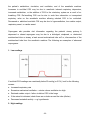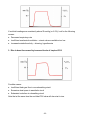
1
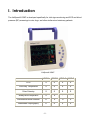
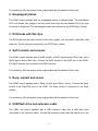
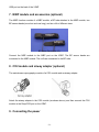
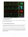
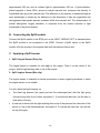
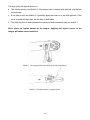
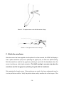
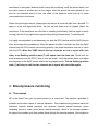
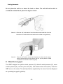
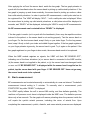
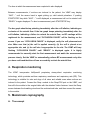
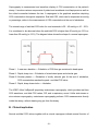
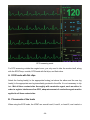
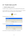
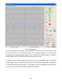
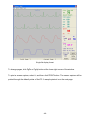
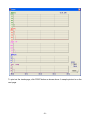
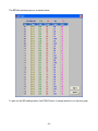
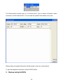
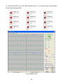
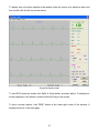
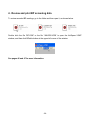
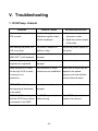
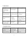
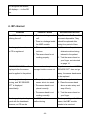
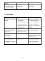
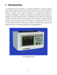
THE VETSPECS® VSM7 VETERINARY DIGITAL VITAL SIGNS MONITOR ECG/BLOOD PRESSURE SCREENING SYSTEM USER’S MANUAL -1- VETSPECS EUROPE CO., LTD. www.VetSpecsEU.com CONTENTS I. Introduction -------------------------------------------------------------------------------- 1 II. Installation ---------------------------------------------------------------------------------- 2 III. Clinical instructions --------------------------------------------------------------------- 5 3.1 Vital signs monitoring ---------------------------------------------------------------------------- 5 1. Esophageal probes --------------------------------------------------------------------------------------- 6 2. Pulse oximetry --------------------------------------------------------------------------------------------- 7 3. Blood pressure monitoring ---------------------------------------------------------------------------- 11 4. Respiration monitoring --------------------------------------------------------------------------------- 15 5. Mainstream capnography -------------------------------------------------------------------------- -2- ----- 16 3.2 Screening -------------------------------------------------------------------------------------------- 23 1. ECG screening ------------------------------------------------------------------------------------------- 23 2. Blood pressure screening ----------------------------------------------------------------------------- 25 IV. Operational instructions ------------------------------------------------------------- 27 4.1 Control panel --------------------------------------------------------------------------------------- 27 4.2 The menu system --------------------------------------------------------------------------------- 28 4.3 Recall stored data -------------------------------------------------------------------------------- 35 4.4 Save information ---------------------------------------------------------------------------------- 35 4.5 Transfer data to your PC ----------------------------------------------------------------------- 37 4.6 Review and print ---------------------------------------------------------------------------------- 39 V. Troubleshooting ------------------------------------------------------------------------ 53 VI. Maintenance ------------------------------------------------------------------------------ 57 -3- VII. Specifications --------------------------------------------------------------------------- 57 VIII. Modules and accessories -----------------------------------------------------------58 IX. Customer services --------------------------------------------------------------------- 58 Limited Warranty ------------------------------------------------------------------------------- 59 -4- I. Introduction The VetSpecs® VSM7 is developed specifically for vital signs monitoring and ECG and blood pressure (BP) screenings in cats, dogs, and other similar-sized veterinary patients. VetSpecs® VSM7 VSM7-A VSM7-B VSM7-C VSM7-D ECG S S S S Core-body Temperature S S S S Pulse Oximetry S S S S Airway-direct Respiration S S - - Noninvasive Blood Pressure O S O S Mainstream Capnography O O S S -5- S - Standard. O - Option which can be added on later without returning the VSM7 to VetSpecs. The VSM7 incorporates VetSpecs® state-of-the-art digital modular platform, and features up to five external digital modules: ECG/Temp. module, SpO2 module, Resp. module, NIBP module, and CO2 module. To use these modules, simply connect them to the corresponding ports on the VSM7. The NIBP module is optional for VSM7-A and C, and the CO2 module is optional for VSM7-A and B. If your VSM7 does not come with the NIBP and/or CO2 modules, you can add them to your VSM7 at any time without returning your VSM7 to VetSpecs. Go paperless in vital signs monitoring and ECG and BP screenings. The VSM7 automatically saves monitoring records (waveforms, readings, and trends), ECG tracings, and BP readings on an included USB flash drive (any flash drives). Simply plug the flash drive into the USB port on the VSM7. After a monitoring or screening, take the flash drive to your personal computer (PC) to transfer the saved information to the PC. You can then review the information, email cases, and present the patient records to your clients directly on your PC or by printing out through any PC-compatible printers. II. Installation 1. ECG/Temp. module Connect the ECG/Temp. module to the ECG/Temp port on the VSM7. -6- For monitoring, affix the module to the surgical table with the attached Velcro strip. 2. Esophageal probes The VSM7 comes standard with two esophageal probes of different sizes. The one labeled CAT is for kittens, cats, puppies, and very small dogs, while the one labeled DOG is for dogs from small to large sizes. The esophageal probes are connected to the ECG/Temp. module. 3. ECG leads with flat clips The ECG leads with flat clips consist of three wires (green, red, and white), each with a flat metal clip. The flat clips are connected to the ECG/Temp. module. 4. SpO2 module and sensors The VSM7 comes standard with a SpO2 module, a SpO2 lingual sensor (Gray clip), and a SpO2 leg/toe sensor (Blue clip). Connect the SpO2 module to the SpO2 port on the VSM7. The SpO2 sensors are connected to the SpO2 module. For monitoring, affix the module to the surgical table with the attached Velcro strip. 5. Resp. module and sensor The VSM7 comes standard with a Resp. module and a Resp. sensor. Connect the Resp. module to the Resp/CO2 port on the VSM7. The Resp. sensor is connected to the Resp. module. For monitoring, affix the module to the surgical table with the attached Velcro strip. 6. USB flash drive and extension cable The VSM7 unit comes standard with a USB extension cable and a USB flash drive (connected to the extension cable). Connect the extension cable (with the flash drive) to the -7- USB port on the back of the VSM7. 7. NIBP module and accessories (optional) The NIBP function consists of a NIBP module, a BP tube attached to the NIBP module, two BP sensor bands (one short and one long), and six cuffs of different sizes. BP Sensor Bands (set of 2) Connect the NIBP module to the NIBP port on the VSM7. The BP sensor bands are connected to the NIBP module. The cuffs are connected to the BP tube. 8. CO2 module and airway adapter (optional) The mainstream capnography consists of a CO2 module and an airway adapter. Attach the airway adapter to the CO2 module (as shown above), and then connect the CO2 module to the Resp/CO2 port on the VSM7. 9. Connecting the power -8- Plug the power cord into the power port on the back of the VSM7, and then into a 3-line 110V/60Hz power outlet in North America or a 3-line 220V/50Hz power outlet in most other countries. For maximum safety, only connect the VSM7 to a power outlet with three lines. III. Clinical instructions 3.1 Vital signs monitoring The VSM7 features three work modes: surgical monitoring mode, ECG screening mode, and BP screening mode. The VSM7 automatically switches to surgical monitoring mode when an esophageal probe is inserted into the patient, i.e. a temperature is registered, or the Resp. module or CO2 module is connected to the VSM7. In surgical monitoring mode, the VSM7 displays cascaded two lines of ECG (green) registered by the esophageal probe, one line of pulse waveforms (red) registered by the SpO2 sensor, and one line of CO2 waveforms (light yellow) when the CO2 module is in use, or one line of respiratory waveforms (white) when the Resp. module is in use. -9- Surgical monitoring mode 1. Esophageal probes The VSM7 registers ECG, heart rate (HR), and core-body temperature in anesthetized patients with a single esophageal probe. A. Choose an appropriate sized probe The esophageal probe labeled DOG is suitable for dogs from small to large sizes, while the esophageal probe labeled CAT is intended for kittens, cats, puppies, and very small dogs. In order for the probe to register stable high-quality ECG, all three metal rings must establish good contacts with the esophagus. If the probe is too small for the patient, it will not be able to establish good contacts with the esophagus. Applying the CAT probe in dogs may produce erratic ECG. - 10 - B. Apply the esophageal probe Connect the esophageal probe to the ECG/Temp. module. Affix the module to the surgical table with the attached Velcro strip. After the patient has been anesthetized and intubated, estimate how deep to insert by laying the probe onto the patient. The distal ring and middle ring should be positioned across the heart after inserted. Insert the probe into the esophagus to the depth as estimated above, and then watch the screen. If registered ECG is erratic, i.e. ECG baseline is unstable, adjust the position (depth) of the probe until stable ECG is registered. Motions induced to the patient and/or probe during the procedure may produce motion artifacts on the ECG. Tie the esophageal probe to the endotracheal probe to minimize motions if necessary. Never insert a probe into a patient not anesthetized and intubated. Do not use a probe which is defective or damaged externally. When using the esophageal probes in electrosurgery, the patient must be properly grounded as instructed in the User’s Manual for the electrosurgical unit being used. 2. Pulse oximetry A. The concept Pulse oximetry provides a noninvasive and continuous estimate of oxygen saturation of hemoglobin in arterial blood. "SpO2" is commonly used when referring to oxygen saturation readings obtained from a pulse oximeter. Pulse oximetry combines the principles of photoelectric plethysmography and spectrophotometry to determine arterial hemoglobin oxygen saturation values. Photoelectric plethysmography uses light absorption technology to reproduce waveforms produced by pulsatile arterial flow. The changes in the absorption of light due to arterial pulsation are reproduced as pulse waveforms. Spectrophotometry is the technology that uses various wavelengths of light to perform quantitative measurements of light absorption through given substances. Pulse oximeters utilize two light-emitting diodes (LEDs) of given wavelengths: a red light at - 11 - approximately 660 nm and an infrared light at approximately 920 nm. A photo-detector, placed opposite to these LEDs, across an arterial vascular bed, measures the intensity of transmitted light across the vascular bed. The difference in the intensity of transmitted light at each wavelength is caused by the difference in the absorption of light by oxygenated and deoxygenated hemoglobin species contained within the vascular bed. The determination of arterial hemoglobin oxygen saturation is computed from the relative amounts of light transmitted to the photo-detector. B. Connecting the SpO2 module Connect the SpO2 module to the SPO2 port on the VSM7. “MODULE OFF” is indicated when the SpO2 module is not connected to the VSM7. Connect a SpO2 sensor to the SpO2 module. Affix the module to the surgical table with the attached Velcro strip. C. Applying a SpO2 sensor 1. SpO2 Lingual Sensor (Gray clip) The lingual sensor is intended for use only on the tongue. Place it at the center of the tongue, with the light-emitting side on top of the tongue. 2. SpO2 Leg/toe Sensor (Blue clip) The leg/toe sensor is intended for dental procedures or those surgical procedures in which the lingual sensor is not suitable. For cats, place the leg/toe sensor on • The distal leg between the carpal pad and the metacarpal pad, with the light going through the leg from front to back, see sketch 1. If covered with dark hair, clip the hair on both sides of the leg. • A paw top to bottom with the light-emitting side on top of the paw and the other side of the sensor on top of the metacarpal pad, see sketch 2. If covered with dark hair, clip the hair on top of the paw. - 12 - For dogs, place the leg/toe sensor on • The Achilles tendon, see Sketch 3. If the sensor site is covered with dark hair, clip the hair on both sides. • A toe side to side, see sketch 4. If possible, apply the sensor to a toe with light skin. If the toe is covered with dark hair, clip the hair on both sides. • The distal leg front to back between the carpal pad and metacarpal pad, see sketch 1. Never place the leg/toe sensor on the tongue. Applying the leg/toe sensor to the tongue will cause vasoconstriction. Sketch 1: The Leg/toe sensor on a distal leg of cats or small dogs. Sketch 2: The leg/toe sensor on a paw of cats. - 13 - Sketch 3: The leg/toe sensor on the Achilles tendon of dogs. Sketch 4: The leg/toe sensor on a toe of dogs. C. Watch the waveforms After the sensor has been applied onto the patient for a few seconds, the VSM7 will display a line of pulse waveforms (red) and a pulsating bar graph (red), as well as a SpO2 reading. Both the waveforms and the bar graph are pulsating in synch with the heartbeats when the sensor is picking up valid arterial pulsations. The SpO2 reading is accurate only when the waveforms and the bar graph are pulsating in synch with the heartbeats. After applying the lingual sensor, if the waveforms are erratic, the tissue underneath may be in a low perfusion condition. Verify the patient status, and try another site on the tongue. If the - 14 - waveforms (or bar graph) become erratic during the monitoring, verify the patient status, and move the sensor to another spot on the tongue. After the sensor has been placed on one spot for an extended period of time, the effect of the pressure could build up to cause vasoconstriction in the tissue. When using the leg/toe sensor, always place the sensor at a site with light skin if possible. To apply to a site with pigmented tissue, the hair on both sides must be clipped. Watch the waveforms. If the waveforms are a flat line or pulsating intermittently (the bar graph is barely moving), the site is too pigmented to permit adequate light transmission. Try another site. It is highly recommended to simultaneously use both the ECG function and the SpO2 function when monitoring during anesthesia. When the patient condition is normal, and both the SpO2 channel and the ECG channel are working properly, the pulse waveforms must be in synch with the ECG. When the VSM7 detects the two channels are not in synch with each other, a red flashing question mark (?) will appear near the heart rate. Check both the pulse waveforms and the ECG. If one or both are erratic, verify the patient status, and adjust the placement of the SpO2 sensor and/or the esophageal probe. The red flashing question mark (?) will stay on until the two channels are in synch with each other again. 3. Blood pressure monitoring A. The concept BP is the lateral force per unit area exerted on a vessel wall. The pressure generated is pulsatile and creates a wave of vascular distention. This forward-moving pressure wave has maximum (systolic arterial pressure) and minimum (diastolic arterial pressure) values oscillating around a mean value (mean arterial pressure), which is the average pressure throughout the cardiac cycle that pushes blood through the vascular network. Since systole is - 15 - normally shorter than diastole, mean arterial pressure (MAP) is not simply the midpoint between systolic arterial pressure (SAP) and diastolic arterial pressure (DAP) but is estimated as MAP = DAP + (SAP - DAP) ÷ 3 The VSM7 incorporates a breakthrough technology for noninvasive BP measurement, called volume plethysmography. This technology employs an inflatable cuff to occlude arterial flow and a pressure sensor band to sense arterial pulsations. Volume plethysmography has been proven to provide accurate systolic, diastolic, and mean arterial pressures, and a real-time pulse rate in cats and dogs of all sizes, and other similar sized animals. B. Choose an appropriately sized cuff and sensor band Cuff size can have a significant influence on the accuracy of a measurement. A cuff that is too narrow will produce artificially elevated readings, while a cuff that is too wide will produce spuriously low values. In theory, the ideal cuff width is about 35 - 40% of the circumference of the cuff site. The VSM7 comes with six cuffs of different sizes. All six cuffs are marked to aid in proper cuff selection. When a cuff is wrapped around a site, its index edge should be within the range indicated on the cuff. The cuff is too small or too large if the index edge is outside the range. The following should be used only as general guidelines for cuff selections, because the circumference and shape of the cuff site, not the size of the patient, matter most. • Size 1 (circumference 4.3 – 6.4 cm) is for kittens and small dogs. • Size 2 (circumference 5.9 – 8.7 cm) is for kittens, cats, and small dogs. • Size 3 (circumference 7.2 – 10.7 cm) is for cats and small dogs. • Size 4 (circumference 8.5 – 12.7 cm) is for small to medium dogs. • Size 5 (circumference 9.0-15.0 cm) is for medium to large dogs. • Size 6 (circumference 15.0-21.5 cm) is for large dogs. The VSM7 comes with one long sensor band and one short sensor band. Generally - 16 - speaking, the long sensor band is for medium and large dogs, while the short sensor band is for cats and small dogs. When applying a sensor band to a site on the patient, the sensor band must allow it to be wrapped tightly around the site. Otherwise, the sensor band is too large for the site to work properly. Apply the short sensor band or try a site with a larger circumference. C. Apply the cuff and sensor band The cuff and the sensor band must be applied onto the same limb or tail. It is not necessary to clip the hair. Apply the cuff, and then the sensor band. The sensor band must be placed distal to (below) the cuff. Place the sensor band over a main artery with the VetSpecs® side facing outside, and then pull the Velcro strip to wrap the sensor band tight. The sensitivity of the sensor band will be reduced if the sensor band is not wrapped firmly enough or not positioned correctly. In order for the cuff to successfully occlude the arterial flow when inflated, the cuff must be placed at an appropriate site, as instructed below. • Place the cuff at the base of the tail and the sensor band half of an inch below the cuff. Position the sensor band over the median coccygeal artery, see sketch 5. Pull the Velcro strip to wrap the sensor band tight. The tail placement is highly recommended for patients with short legs and for conscious patients, especially cats. Cats tolerate much better the tail placement. • For cats or dogs with long legs, the cuff may be placed below the hock and the sensor band half of an inch distal to the cuff. Do not place the cuff above the hock. The rear leg placement may not be suitable for patients with short legs. • Place the cuff and the sensor band between the elbow and the carpus with the sensor band about one inch distal to the cuff, see sketch 6. Lay the patient in lateral recumbence to minimize the effect of gravity. Conscious cats usually do not tolerate well the - 17 - foreleg placement. Do not place the cuff on or above the hock or elbow. The cuff will not be able to occlude the arterial flow if placed too high on a limb. Sketch 5: Place the cuff at the base of the tail and the sensor band half of an inch below the cuff. Position the sensor band over the median coccygeal artery. Sketch 6: Place the cuff and the sensor band between the elbow and the carpus, with the sensor band one inch distal to the cuff. Lay the patient in lateral recumbence to minimize the effect of gravity. D. Watch the bar graph The VSM7 displays the systolic arterial pressure (S), diastolic arterial pressure (D), mean arterial pressure (M), real-time pulse rate (PR), and measurement interval (INT.) inside the NIBP zone on the screen. The arterial pulsations registered by the sensor band are displayed as a pulsating bar graph (light blue). - 18 - After applying the cuff and the sensor band, watch the bar graph. The bar graph pulsates in synch with the heartbeats when the sensor band is picking up valid arterial pulsations. If the bar graph is jumping up and down erratically, the sensor band is picking up motions, rather than valid arterial pulsations. In order to perform BP measurements, a valid pulse rate has to be registered first. The VSM7 will display “WAIT…” until a valid pulse rate is displayed. When the sensor band is picking up valid arterial pulsations, a valid pulse rate will be displayed in seconds, and “READY” will be displayed, indicating the VSM7 is ready for BP measurements. No BP measurements can be started before “READY” is displayed. If the bar graph is erratic (not in synch with the heartbeats), there may be repetitive motions induced to the patient, or the sensor band is not working properly. Test the sensor band on your finger. For the short sensor band, wrap it firmly on your index finger. For the long sensor band, wrap it firmly on both your index and middle fingers together. If the bar graph registered on your finger pulsates vigorously, the sensor band is good. Try it again on the patient. If the bar graph registered on your finger is also erratic, the sensor band needs to be replaced. When the NIBP module registers no signals, the VSM7 will flash “BP SENSOR OFF”, indicating one of the three situations: (a) no sensor band is connected to the NIBP module; (b) the sensor band is not applied to the patient; or (c) the sensor band was damaged inside or worn out. If “BP SENSOR OFF” is displayed while the sensor band is applied on the patient, tap the sensor band with your finger. If “BP SENSOR OFF” does not go away, the sensor band needs to be replaced. E. Start a measurement BP measurements can be started manually or automatically at a user-set interval. The default measurement interval setting is 3 minutes. To manually start a measurement, push START/STOP key while “READY” is displayed. The VSM7 rapidly inflates the cuff to around 280 mmHg, and then deflates gradually. The real-time cuff pressure count down is displayed inside the NIBP zone. The deflation process takes only a few seconds. The bar graph will resume pulsating when the pressure inside the cuff equals the systolic arterial pressure, indicating the return of arterial flow. Upon completing the measurement, systolic, diastolic, and mean arterial pressures are displayed. - 19 - The time at which the measurement was completed is also displayed. Between measurements, if motions are induced to the patient, the VSM7 may display “WAIT…” until the sensor band is again picking up valid arterial pulsations. If pushing START/STOP key while “WAIT…” is still displayed, a measurement will not be started until “READY” is again displayed. To abort a measurement, push START/STOP key. The bar graph should stop pulsating immediately after the cuff inflation, indicating an occlusion of the arterial flow. If the bar graph keeps pulsating immediately after the cuff inflation, indicating a failure to occlude the arterial flow, no BP readings will be registered for the measurement, and “OCCLUSION FAILED” will be flashing on the screen. If you see “OCCLUSION FAILED” is displayed, verify the cuff placement and size. Make sure that (a) the cuff is applied correctly, (b) the cuff is placed at an appropriate site, and (c) the cuff size is appropriate for the site. The VSM7 will keep flashing “OCCLUSION FAILED” until “READY” is displayed again. It is highly recommended to manually start the first measurement and watch the measurement process closely. Set the VSM7 to automatically perform BP measurements only after you have confirmed that the cuff can successfully occlude the arterial flow. 4. Respiration monitoring The VSM7 incorporates VetSpecs® proprietary airway-direct respiration monitoring technology, which provides real-time respiratory waveforms and respiratory rate (RR). This technology is suitable for cats and dogs of all sizes and reliable even when motions are induced to the patient. Connect the Resp. module to the Resp/CO2 port on the VSM7, and then affix the module to the surgical table with the attached Velcro fastener. Insert the Resp. sensor between the breathing circuit and the endotracheal tube, and then connect the sensor to the module. 5. Mainstream capnography A. The concept - 20 - Capnography is measurement and waveform display of CO2 concentration at the patient’s airway. It monitors various components of patient and anesthesia circuit/equipment as well as the critical connection between the two. A capnogram is the graphical waveform depicting CO2 concentration throughout respiration. End-tidal CO2, which can be expressed as mmHg or percentage, refers to the measurement of CO2 concentration at the end of exhalation. The normal range of end-tidal CO2 value for most mammals is 30 – 45 mmHg or 4.0 – 5.5%. It is considered to be abnormal when the end-tidal CO2 is higher than 50 mmHg (or 6.5%) or lower than 20 mmHg (or 2.5%). The diagram below shows the shape of a normal capnogram. Phase I: A near zero baseline — Exhalation of CO2-free gas contained in dead space. Phase II: Rapid, sharp rise — Exhalation of mixed dead space and alveolar gas. Phase III: Alveolar plateau — Exhalation of mostly alveolar gas. At the end of exhalation, CO2 concentration reaches the peak - end-tidal CO2 value. Phase 0: Rapid, sharp down-stroke — Inhalation. The VSM7 offers VetSpecs® proprietary mainstream capnography, which provides real-time CO2 waveforms, end-tidal CO2 values, RR, and a respiratory sound. Unlike side-stream or micro-stream capnography, mainstream capnography performs CO2 measurements directly inside the airway, without drawing any gas from the airway. B. Clinical implication Normal end-tidal CO2 values together with a normal capnogram indicate normal function of - 21 - the patient’s metabolism, circulation, and ventilation, and of the anesthetic machine. Increases in end-tidal CO2 may be due to anesthetic induced respiratory depression, increased metabolism, or the addition of CO2 to the circulatory system as a result of rebreathing CO2. Re-breathing CO2 can be due to soda lime exhaustion or incompetent expiratory valve on the anesthetic machine allowing exhaled CO2 to be re-inhaled. Decreased or abolished end-tidal CO2 may be due to hyperventilation, low cardiac output, respiratory arrest, or cardiac arrest. Capnogram also provides vital information regarding the patient's airway potency. A depressed or absent capnogram may be due to a dislodged, misplaced, or obstructed endotracheal tube or airway, a leak around endotracheal tube cuff or, disconnection of the endotracheal tube from the anesthetic machine. The following are examples of abnormal capnograms. 1. Low readings If end-tidal CO2 readings are consistently below 20 mmHg (or 2.5%), look for the following causes: ● Increased respiratory rate ● Excessive mechanical ventilation – minute volume ventilation too high ● Reduced cardiac output – failure to deliver CO2 to the lungs ● If the animal is intubated, check there are no leaks around the tube (dilution) ● Decreased metabolic activity – e.g. hypothermia 2. High readings - 22 - If end-tidal readings are consistently above 50 mmHg (or 6.5%), look for the following causes: ● Decreased respiratory rate ● Insufficient mechanical ventilation – minute volume ventilation too low ● Increased metabolic activity – shivering, hyperthermia 3. Rise in base-line caused by increased levels of inspired CO2 Possible causes: ● Insufficient fresh gas flow in non-rebreathing circuit ● Excessive dead space in anesthetic circuit ● Exhausted soda-lime in rebreathing circuit Note that at the same time the end-tidal CO2 value will also start to rise. - 23 - 4. Increase in the slope of phase II and phase III Possible causes: Reduced ability to expire – e.g. ● Block ET tube ● Bronchial disease / asthma ● Upper airway obstruction ● Faulty expiratory valve 5. Abrupt fall in end-tidal CO2 level Possible causes: any effect leading to sudden reduced cardiac output ● Pulmonary artery compression ● Pulmonary artery embolism ● Sudden hemorrhage ● Acute cardiac tamponade ● Cardiac compression - 24 - 6. Differential emptying The above capnograms can result from the following: ● Positioning of the ET tube at or beyond the carina, so that one side of the lung has impaired emptying. This makes the retained gas higher in CO2 and later to empty than from the normal lung. The “spike” can occur anywhere in the plateau phase. ● Any functional blockage of a major airway, below the carina – foreign body, mucous, compressed airway, etc. 7. Cardiogenic oscillations - 25 - Cardiogenic oscillations are ripples superimposed on the expiratory plateau and the descending limb of the capnogram, which are caused by small gas movements inside the airway. Although cardiogenic oscillations can occur in any animal where the pulsations of the aorta and heart cause areas of lungs to be compressed and thereby emptied and filled, they are typically seen in large dogs with a slow RR. The guide to the fact that this is happening is that the oscillations are in synch with the heartbeats. The displayed respiratory rate can be much higher than the actual respiratory rate when cardiogenic oscillations occur. C. Operation instructions 1. CO2 module calibration The CO2 module will automatically start calibrating upon being powered on. In other words, turning on the VSM7, or connecting the CO2 module to the VSM7, automatically triggers the CO2 module to calibrate. The calibration takes three minutes. To ensure the CO2 module to be calibrated correctly, follow these steps. 1. Attach the airway adapter on the CO2 module (see page 4) before connecting the CO2 module to the VSM7. Do not power on the CO2 module without the airway adapter. 2. Turn on the VSM7, and connect the CO2 module to the VSM7. During the entire calibration process, both ends of the airway adapter must be open in the air and away from the patient. When the CO2 module is being calibrated, the VSM7 displays “CO2 CALIBRATION” and “CAL”. Upon completing the calibration, “CO2 CALIBRATION” and - 26 - “CAL” go away. Do not insert the airway adapter between the breathing circuit and the endotracheal tube before the calibration is completed. If CO2 was detected during the calibration process, or the CO2 module failed to be calibrated properly, “PLEASE RE-CALIBRATE” (red) would be displayed. You would need to re-calibrate the CO2 module by unplugging it from the VSM7 and then replugging it back. 3. During a monitoring, if the VSM7 is turned off, or the CO2 module is disconnected from the VSM7, you must re-calibrate the CO2 module before continuing the CO2 monitoring. Disconnect the airway adapter from both the breathing circuit and the endotracheal tube, place the CO2 module (with the airway adapter) away from the patient, and then turn on the VSM7 or reconnect the CO2 module to the VSM7. After the calibration is completed, re-insert the airway adapter to the breathing circuit and the endotracheal tube. 2. CO2 monitoring Insert the airway adapter between the breathing circuit and the endotracheal tube. CO2 waveforms, an end-tidal CO2 reading, and a RR should be displayed instantly. The CO2 waveforms indicate the real-time airflow in and out the patient. If the CO2 waveforms are erratic, check the patient status and the placement of the endotracheal tube. Adjust the endotracheal tube and/or bag the patient if necessary. During a monitoring, if “PLEASE RE-CALIBRATE” is displayed, disconnect the airway adapter from both the breathing circuit and the endotracheal tube, and then re-calibrate the CO2 module. If the patient stops breathing (both RR and ETCO2 drop to 00) for more than 30 seconds, an alarm will be sounded. Pushing ALARM key only suspends the alarm for one minute. After a monitoring, disconnect the airway adapter from both the endotracheal tube and the breathing circuit, but leave the airway adapter on the CO2 module. After an airway adapter - 27 - has been used for a number of times, it may need to be replaced. Generally speaking, if the CO2 function does not work properly, the airway adapter needs to be replaced. To ensure the best performance, replace the airway adapter frequently. D. Digital respiratory sound The CO2 module offers a digital respiratory sound originated from real-time CO2 measurements. The rhythm of the sound reflects the respiratory rate. The respiratory sound allows continuously assessing the patient’s respiratory status without constantly watching the screen. The respiratory sound can be set ON or OFF in the menus, and the setting will be saved as default. The volume of the sound can be adjusted with the VOLUME Dial. 3.2 Screening 1. ECG screening The VSM7 features ECG leads with flat clips, designed specifically for ECG screening in cats, dogs, and other similar-sized animals. The VSM7 automatically enters into ECG screening mode, displaying cascaded four lines of ECG on one screen, when the ECG leads are applied on the patient and both the Resp. module and the CO2 module are not connected to the VSM7. - 28 - ECG screening mode For ECG screening outside the surgical room, you only need to take the monitor itself, along with the ECG/Temp. module, ECG leads with flat clips, and flash drive. A. ECG leads with flat clips Attach the foreleg lead(s) to the appropriate foreleg just above the elbow and the rear leg lead(s) to the appropriate rear leg immediately proximal to the stifle. It is not necessary to clip hair. Wet all three contact sites thoroughly with conductive agent, such as saline. In order to register interference-free ECG, adequate amount of conductive agent must be applied to all three contact sites. B. Placements of the leads When using the ECG leads, the VSM7 can record Lead-I, Lead-II, or Lead-III, one Lead at a - 29 - time. Lead-II is the Lead of choice for both monitoring and screening. Placements of leads for recording different Leads of ECG are listed as below: LEAD-II ECG GREEN lead attaches to RIGHT REAR LEG RED lead attaches to LEFT REAR LEG WHITE lead attaches to RIGHT FORELEG LEAD-I ECG GREEN lead attaches to RIGHT REAR LEG RED lead attaches to LEFT FORELEG WHITE lead attaches to RIGHT FORELEG LEAD-III ECG GREEN lead attaches to RIGHT REAR LEG RED lead attaches to LEFT REAR LEG WHITE lead attaches to LEFT FORELEG The patient should be laid on its side, usually on a towel or rubber mat, and relaxed. Trembling and panting may produce motion artifacts on ECG. For more instructions on ECG screening, read pages 36 – 38 and 49 – 51. 2. Blood pressure screening The VSM7 automatically enters into BP screening mode when only the NIBP module is connected to the VSM7. For BP screening, connect only the NIBP module to the VSM7, and then place the NIBP module close to the patient to prevent the weight of the module from being applied to the patient. For more instructions on BP measurements, see pages 11 – 15. - 30 - A. Screening for hypertension Screening for hypertension must be performed in a quiet environment under a stress-free condition. If possible, have two people to do the job. One holds and calms the patient while the other places the cuff and the sensor band and operates the VSM7. It is highly recommended to place the cuff and sensor band on the tail. See sketch 5 on page 13. Cats usually tolerate much better the tail placement. Apply the cuff first, and the sensor band, and then calm down the patient. After the patient is calmed down, connect the cuff and the sensor band to the NIBP module. The patient must be calmed down before starting a measurement. Do not start a measurement when the patient is constantly struggling, panting, trembling, or shivering. No technologies can measure BP effectively when there are repetitive motions on the patient. Furthermore, it makes no sense to measure BP when the patient is obviously under stress. Watch the bar graph. If the bar graph is pulsating erratically, i.e. it is not in synch with the heartbeats, the patient is not relaxed. Even when there are no visible body motions, the muscles underneath the sensor band may still be too tense, producing minute muscle movements. Continue to calm the patient. After the patient is calmed down, the bar graph will pulsate in synch with the heartbeats. As soon as “READY” is displayed, you can push the START/STOP key to start a measurement. For BP screening in conscious patients, it is recommended to set the measurement interval at 0.5 or 1 minutes, or to manually start each measurement. B. Systemic hypertension The diagnosis of systemic hypertension may be made in a cat of any age with a systolic pressure over 190 mmHg. Cats with clinical findings compatible with hypertension and systolic pressures between 160–190 mmHg should also be considered hypertensive, particular in cats < 14 years old. In the absence of clinical findings of hypertension, cats with a systolic pressure between 160 – 190 mmHg should have measurements repeated many - 31 - times over the course of a day. In general, dogs with a systolic pressure over 180 mmHg are considered hypertensive. Care has to be taken in diagnosing hypertension as marked breed differences occur. These are not absolute limits, just a guideline for each individual case. Repeated measurement helps clarify whether the elevation in pressure is sustained or stress-induced. Results always need to be interpreted carefully in light of the animal’s condition and measurement environment. If the same patient is to be measured at different times, cuff size and position should be matched as close as possible. C. BP measurements in hypotensive patients In order for the sensor band to pick up valid arterial pulsations in hypotensive patients, place the sensor band at a site with better circulation, position the sensor band right above a main artery, and wrap the sensor band tight. If necessary, clip the hair underneath the sensor band. If the sensor band cannot pick up valid arterial pulsations, try another location. The sensor band may not be able to pick up valid arterial pulsations when the circulation underneath is too weak. Failure to pick up arterial pulsations by the sensor band at multiple locations is an indication of severe hypotension. For more instructions on BP screening, refer to pages 35 – 38, 46 – 47, and 52. IV. Operational instructions To turn on or off the VSM7, push the POWER button at the upper left corner on the back. Always turn off the VSM7 to refresh the internal memory after a monitoring or screening. Otherwise, the data of the previous patient will be mixed with the data of the next patient. - 32 - 4.1 Control panel TREND Push the TREND key to switch displaying real-time waveforms and readings, stored BP readings, and registered trends. SAVE In surgical monitoring mode, push the SAVE key to save information on the flash drive. ♥BEAT Push the ♥BEAT key to turn off or on the heartbeats sound. FREEZE Push the FREEZE key to freeze a line of ECG on the screen. Push the FREEZE key again to release the line. START/STOP Push the START/STOP key to manually start a BP measurement. Pushing the START/STOP key before a measurement has completed aborts the measurement. ALARM Push the ALARM key to suspend or turn on an alarm. For CO2 alarm, one push on the ALARM key suspends the alarm for one minute. JOG DIAL - 33 - Push the JOG DIAL to display main menu. Turn the JOG DIAL to select items in main menu or submenus. VOLUME Dial Turn the VOLUME Dial to increase or decrease the volume of the speaker. 4.2 The menu system Main menu Push the JOG DIAL to display main menu. Turn the JOG DIAL to select a submenu, and then push the JOG DIAL to enter the selected submenu. To exit from main menu, select ESC and push the JOG DIAL. 1. Pet Name 2. CO2 3. SCREEN 4. NIBP 5. ECG 6. SPO2 7. Temp. 8. SETUP MENU 9. ESC Pet Name The VSM7 will prompt you to enter a patient name as soon as a monitoring or screening is started. The VSM7 will beep for ten seconds, and keep flashing “PET NAME” until a patient name is entered. - 34 - A patient name can be entered ONLY when a flash drive is plugged in and “PET NAME” is flashing on the screen. To enter a patient name, push the JOG DIAL and turn it to select the line under Pet Name. • Push the JOG DIAL to generate a red cursor, rotate the JOG DIAL to input the first letter (A to Z) or digit (0 – 9), and then push the JOG DIAL to enter. • Rotate the JOG DIAL to input the second letter or digit, and then push the JOG DIAL to enter. A total of eight letters and/or digits can be entered. • After entering all letters and digits, push the JOG DIAL until the red cursor disappears. The patient name is displayed at the bottom of the screen, and a new folder named with the patient name is created on the flash drive. No new folder will be created on the flash drive until a new patient name is entered. Upon entering a new patient name, BP readings and trends data stored in the internal memory of the VSM7 will be erased, making the system ready for the new patient. The information already saved on the flash drive will not be deleted. If a folder with the same patient name has already existed on the flash drive, the word “EXISTED” will be displayed briefly upon entering. Enter a different name or delete the folder with the same name from the flash drive. If you do not want to save any information for a procedure, just do not enter a name and ignore the flashing “PET NAME”. CO2 • Select CO2 and push the JOG DIAL to enter CO2 submenu as below: 1. 2. Sound: Unit: - 35 - OFF mmHg 3. 4. 5. 6. 7. 8. HI: LO: Alarm: Speed: RETURN ESC 50 20 ON Slow The VSM7 features a digital respiratory sound when the CO2 function is in use. The respiratory sound can be set OFF or ON as default. To turn on or off the respiratory sound, • Select SOUND: OFF, and push the JOG DIAL to highlight in red. • Turn the JOG DIAL to change to ON, and then push the JOG DIAL to set. The heartbeats sound is turned ON when the respiratory sound is turned OFF. The end-tidal CO2 can be expressed as mmHg (default) or percentage. The user can select one of the two units and set it as default. To change the unit: • Select units: mmHg, and push the JOG DIAL to highlight in red. • Turn the JOG DIAL to change the unit, and then push the JOG DIAL to set. To change end-tidal CO2 alarm limits: • Select the item to be changed, push the JOG DIAL to highlight in red. • Turn the JOG DIAL to change the number, and push the JOG DIAL to set. The default alarm setting for end-tidal CO2 is ON. To change the alarm setting to OFF: • Select Alarm: ON, and push the JOG DIAL to highlight in red. • Turn the JOG DIAL to change to OFF, and then push the JOG DIAL to set. The respiratory waveforms or CO2 waveforms have two speeds: slow (12.5 mm/s) and fast (the same speed as the ECG). To change waveform speed: • Select Speed: Slow, and push the JOG DIAL to highlight in red. • Turn the JOG DIAL to change to Fast, and then push the JOG DIAL to set. SCREEN - 36 - • Select SCREEN in main menu and push the JOG DIAL to enter SCREEN submenu as below: 1. 2. 3. 4. 5. WAVE SPEED: 50 mm/s NIBP PAGE: 1/1 TREND: 1h RETURN ESC A. WAVE The VSM7 features three waveform speeds: 25, 50 (default), and 100 mm/s. • Select SPEED: 50 mm/s, and then push the JOG DIAL to highlight in red. • Turn the JOG DIAL to change the speed, and then push it to set. B. NIBP While the NIBP module is connected to the VSM7, • Turn the JOG DIAL to select PAGE: 1/1, and then push the JOG DIAL. The first page of stored BP readings will be displayed on the screen. • Turn the JOG DIAL to change page numbers. Push the JOG DIAL to return to real-time waveforms display. C. TREND • Turn the JOG DIAL to select TREND: 1h, and then push the JOG DIAL. The trends of the last one hour (1-hour trends) will be displayed on the screen. • Turn the JOG DIAL to change between the 1-hour trends and the 4-hour trends. Push the JOG DIAL to return to real-time waveforms display. NIBP - 37 - While the NIBP module is connected to the VSM7, select NIBP in main menu and push the JOG DIAL to enter NIBP submenu as below: 1. Interval 2. 3. Alarm: SAP HI: LO: DAP HI: LO: MAP HI: LO: RETURN ESC 4. 5. 6. 7. 3min OFF 180 60 120 40 150 50 A. INTERVAL To change the interval setting for automatic BP measurements (default 3 minutes), • Select 3 min, and then push the JOG DIAL to highlight in red. • Turn the JOG DIAL to change the setting, and then push the JOG DIAL to set. B. ALARM The default setting for BP alarm is OFF. To turn on BP alarm, • Select Alarm: OFF, and push the JOG DIAL to highlight in red. • Turn the JOG DIAL to change to ON and then push the JOG DIAL to set. C. CHANGE BP ALARM LIMITS • Select the item to be changed, push the JOG DIAL to highlight in red. • Turn the JOG DIAL to change the number, and push the JOG DIAL to set. ECG - 38 - Select ECG in main menu and push the JOG DIAL to enter ECG submenu as below: 1. 2. 3. 4. 5. 6. HI: LO: Gain: Alarm: RETURN ESC 400 50 AUTO ON A. CHANGE HR ALARM LIMITS • Select the item to be changed, push the JOG DIAL to highlight in red. • Turn the JOG DIAL to change the number, and push the JOG DIAL to set. B. GAIN: AUTO The ECG amplifier features automatic sensitivity adjustment. “GAIN: AUTO” indicates that the ECG amplifier will automatically adjust its sensitivities (gain) among six levels (X½, X1, X2, X4, X8, and X16) to display ECG in an optimal size (as large as possible without saturation). The red bar (10 mm high) displayed in the ECG channel provides a scale (mV) for measuring the amplitude of the ECG on the screen. To suspend the automatic sensitivity adjustment, change GAIN: AUTO to GAIN: CAL, the gain of the ECG amplifier will be fixed at X1. SPO2 Select SPO2 in main menu and then push the JOG DIAL to enter SPO2 submenu as below: 1. 2. 3. 4. 5. HI: LO: Alarm: RETURN ESC To change SpO2 alarm limits, - 39 - 100 90 ON • Select the item to be changed, push the JOG DIAL to highlight in red. • Turn the JOG DIAL to change the number, and push the JOG DIAL to set. Temp. Select Temp. in main menu and then push the JOG DIAL to enter Temp. submenu as below: 1. 2. 3. 4. 5. 6. Units: HI: LO: Alarm: RETURN ESC F 105 95 ON To change alarm limits, • Select the item to be changed, push the JOG DIAL to highlight in red. • Turn the JOG DIAL to change the number, and push the JOG DIAL to set. SETUP MENU Select SETUP MENU in main menu and push JOG DIAL to enter SETUP MENU as below: 1. 2. 3. 4. Time Date RETURN ESC h: m: s m: d: y To change the time and/or date, • Select the item to be changed, and push the JOG DIAL to highlight in red. • Turn the JOG DIAL to change setting, and push the JOG DIAL to set. - 40 - 4.3 Recall stored data 1. Recall BP readings The VSM7 stores, in its internal memory, BP readings of up to 58 measurements. Push the TREND key to display stored BP readings. Turn the JOG DIAL to change pages. The VSM7 automatically calculates the averages of registered BP readings, and displays the averages at the top of the table. Turning off the VSM7 or disconnecting the NIBP module from the VSM7 will erase all BP readings stored in the internal memory. However, the data already saved in the flash drive will not be deleted. 2. Recall trends The VSM7 stores, in its internal memory, up to four hours of trends (HR, SpO2, Temp., RR, and CO2), and can display these trends in one-hour or four hour formats. Push the TREND key to display the trends. Turn the JOG DIAL to switch between displaying the trends of the last one hour and displaying the trends of the last four hours. 4.4 Save information Plug the flash drive directly, or through the USB extension cable, to the USB port on the back of the VSM7. The VSM7 can not permanently save information without the flash drive. “NO DISK” is indicated at the bottom of the screen when the flash drive is not plugged in. 1. Enter a patient name See page 29 for detailed instructions on how to enter a patient name. A new folder will automatically be created on the flash drive upon entering a new patient - 41 - name. The VSM7 will not save information on the flash drive until a patient name is entered. 2. Save in surgical monitoring In surgical monitoring mode, the VSM7 will automatically save, on the flash drive, information on the screen (screen capture), along with the trends and BP readings, every five minutes. In other words, after a surgical monitoring, a number of screen captures, one trends page, and one BP readings page are saved in the folder of the patient on the flash drive. Any time during a monitoring, you also can save by pushing the SAVE key. The VSM7 will save a new screen capture, and at the same time update the trends page and the BP readings page, on the flash drive. 3. Save in ECG screening When the VSM7 is used for ECG screening (using the ECG leads with flat clips), it automatically and continuously saves ECG on the flash drive. The VSM7 will automatically start saving ECG (screen captures) upon registering valid ECG, and automatically stop saving when ECG is no longer registered. Up to 99 screen captures can be saved in one screening. 4. Save in BP screening For BP screening, with only the NIBP module connected to the VSM7, the VSM7 automatically enters into the BP screening mode, in which the VSM7 automatically saves all registered BP readings on the flash drive. In other words, upon completing a BP screening, all registered BP readings, along with the averages of all the readings, are already saved on the flash drive. Up to 58 sets of individual measurement results can be saved in one screening. - 42 - 4.5 Transfer data to your PC 1. Install the software to your PC The VSM7 PC software is compatible with any PCs using Windows® XP operating system. Insert the software CD into a CD drive on the PC, and then open the CD. To install the program on the PC, simply double click the file named “VetSpecs VSM7.EXE”. The window below pops up. Click Yes button. The window below pops up. Click OK button. An icon named “vsm7” appears on the desktop of the PC, as shown below: - 43 - 2. Create a master folder on the hard drive It is highly recommended to establish a new folder on the hard drive to be the master folder for storing all patient data recorded by the VSM7 before you transfer any data to the PC. You can give any name to the master folder. For example, you can name it “My VetSpecs Data”. 3. Transfer data to the hard drive Remove the flash drive from the VSM7, and insert it to a USB port on the PC. The flash drive should be recognized by the PC automatically, and indicated as Removable Disk under My Computer. It is highly recommended that you copy all folders on the flash drive to the master folder or a folder inside the master folder on the same day they were recorded, and then delete all folders on the flash drive. Otherwise, you may get confused with the folders on the flash drive. Immediately after these folders are copied to the PC, you should rename these folders in a way that they can be identified easily. For example, you may rename a patient’s folder with the patient’s name, ID number, or name + ID number as below: There can be multiple folders inside a patient’s folder. For example, the data recorded in a surgical monitoring on July 1, 2005 are stored in the folder “SM-07-01-05”, the data recorded - 44 - in an ECG screening on July 1, 2005 are stored in the folder “ECG-07-01-05”, and the data recorded in a BP screening on July 1, 2005 are stored in the folder “BP-07-01-05”. 4.6 Review and print 1. Open the program from the desktop Double click the icon “vsm7” on the desktop to open the program. A window titled VetSpecs VSM7 pops up as shown below. - 45 - Click the Open button located at the lower right corner of the window, or click File menu and select Open, as shown below, to go to the patient’s folder. If you see the window is partially out of the screen, the screen resolution setting on the PC is too low to display the entire window. You need to adjust the screen resolution. Go to Control Panel window and double click Display icon, as shown below. In Display Properties window, click Settings. In the window below, set Screen resolution to 1024 by 768 pixels or higher, and then click Apply button and OK button. - 46 - 2. Review and print surgical records To review saved surgical records, go to the folder and then open it. In the folder, you will see a number of files, WAVE00.VSM, WAVE01.VSM, WAVE02.VSM ……… are screen capture files, TREND.VSM is the trends page, and BP.VSM is the BP readings page. You can open any of these files by double clicking on the file, as shown below. - 47 - Four-file display format Four screen captures are opened up in one window. To select one of the four files, click the file (see the picture on the previous page). The readings displayed at the right side correspond to the selected screen capture. You can delete any screen captures. To delete a screen capture, select it, and then click the right key on the mouse. To display only one screen capture, place the cursor in the waveform area of a selected screen capture, and then double click the left key. The selected screen capture is displayed in the whole window, as shown below. To go back to the four-file display format, place the cursor in the waveform area, and then double click the left key. - 48 - Single-file display format To change pages, click PgDn or PgUp button at the lower right corner of the window. To print a screen capture, select it, and then click PRINT button. The screen capture will be printed through the default printer of the PC. A sample printout is on the next page. - 49 - To view trends, in a screen capture window, click Trend button at the upper left corner of the window, as shown below. The TREND window pops up, as shown below. - 50 - To print out the trends page, click PRINT button as shown above. A sample printout is on the next page. - 51 - To view BP readings table, in a screen capture window, click BPtable button at the upper left corner of the window. - 52 - The BPTable window pops up, as shown below. To print out the BP readings table, click PRINT button. A sample printout is on the next page. - 53 - To input patient information, click PetInfo button at the upper left corner of the window. - 54 - The PetInformation window pops up, as shown below. Type in patient information and/or comments, and click Save button. You can make an update in this window at any time. When printing, the patient information will be printed on the top of each printout. To print the diagnostic comments, click the PRINT button. 3. Review and print ECG - 55 - To review saved ECG, go to the folder and then open it. You can open any screen capture file by double clicking the file. Four-file display format - 56 - To display only one screen capture in the window, place the cursor in its waveform area, and then double click the left key on the mouse. Single-file display format To view ECG screen by screen, click PgDn or PgUp button, as shown above. To display four screen captures in one window, double click the left key on the mouse. To print a screen capture, click PRINT button at the lower right corner of the window. A sample printout is on the next page. - 57 - - 58 - 4. Review and print BP screening data To review recorded BP readings, go to the folder and then open it, as shown below. Double click the file “BP.VSM” or the file “WAVE00.VSM” to open the VetSpecs VSM7 window, and then click BPtable button at the upper left corner of the window. See pages 46 and 47 for more information. - 59 - V. Troubleshooting 1. ECG/Temp. channel Problems Possible Causes After inserting the probe, the Not all metal rings have ECG is erratic. established a good contact with the esophagus. Recommended Actions 1. Make sure an appropriate size probe is used. 2. Adjust the position (depth) of the probe. After inserting the probe, the The probe is inserted too Adjust the position (depth) of ECG is too small. shallow or deep. the probe. After inserting the probe, A wire inside the probe was Use another probe. “LEAD OFF” is still displayed. damaged. After inserting the probe, no A wire inside the probe was temperature is registered. damaged. When using the ECG leads Good electrode-to-tissue Make sure all three clips are with flat clips, ECG is erratic contacts are not established. applied to the patient Use another probe. or having a lot of properly, and soak all three interference. contact sites with saline. “LEAD OFF” is still displayed, A lead (wire inside) was after applying all three leads damaged. Use another set of leads. on the patient. “MODULE OFF” is displayed The ECG/Temp. module is The ECG/Temp. module while the ECG/Temp. module malfunctioning. needs to be serviced. is connected to the VSM7. - 60 - 2. SpO2 channel Problems Possible Causes “PROBE OFF” is displayed A wire inside the SpO2 while a SpO2 sensor is sensor was damaged. Recommended Actions Use another SpO2 sensor. connected to the SpO2 module. After applying the leg/toe No adequate light 1. Clip the hair on both sides. sensor, the pulse waveforms transmission due to dark hair, 2. Apply the sensor to a site are erratic or just a flat line. pigmented skin, and/or thick with light skin. tissue. After applying the lingual 1. Low perfusion at the sensor, the pulse waveforms are erratic. sensor site. 2. The sensor is malfunctioning. 1. Check the patient status. 2. Try the sensor on your finger. If the sensor works normally, try it again on the patient. “MODULE OFF” is displayed The SpO2 module is The SpO2 module needs to while the SpO2 module is malfunctioning. be serviced. connected to the VSM7. 3. Respiration channel Problems Possible Causes Recommended Actions The respiratory waveforms A wire inside the Resp. are a flat line. sensor was damaged. After the Resp. module is The Resp. module is The Resp. module needs to connected, the VSM7 does malfunctioning. be serviced. - 61 - Use another Resp. sensor. not recognize the module, still displays in the RR box. 4. BP channel Problems The NIBP module keeps inflating the cuff. Possible Causes 1. There is a leakage on the cuff. the NIBP module. no PR is registered. Try different cuffs. The cuffs are semi-disposable. They 2. There is a leakage inside The bar graph is erratic, and Recommended Actions 1. There are repetitive motions. should be replaced after using for a period of time. 1. Calm down the patient, or eliminate motions being 2. The sensor band is not working properly. induced to the patient. 2. Test the sensor band on your finger, as instructed on page 14. “BP SENSOR OFF” is still The sensor band may be Tap the sensor band. If “BP displayed after the sensor damaged inside or worn out. SENSOR OFF” does not go band is applied to the patient. away, the sensor band needs to be replaced. The bar graph is barely moving, and “BP SENSOR OFF” is displayed intermittently. 1. The perfusion at the sensor site is too weak. 2. The sensor band is not placed correctly. 3. The sensor band is not working normally. 1. Check the patient status. 2. Place the sensor band above a main artery and wrap it firmly. 3. Test the sensor band on your finger. The bar graph is pulsating in The NIBP module is Test on your finger. If still the synch with the heartbeats. malfunctioning. same, the NIBP module However, no PR can be needs to be serviced. - 62 - registered. “MODULE OFF” is displayed The NIBP module is The NIBP module needs to while the NIBP module is malfunctioning. be serviced. connected to the VSM7. 5. CO2 channel Problems Possible Causes Recommended Actions “PLEASE RE-CALIBRATE” is 1. CO2 was detected during Re-calibrate the CO2 module displayed. the calibration. 2. The CO2 module failed to be calibrated properly. 3. Registered CO2 value is erroneously high. as instructed on pages 21 and 22. If the CO2 module still cannot be calibrated properly, try another airway adapter. CO2 waveforms stay a flat The CO2 module was Re-calibrate the CO2 module line, and both CO2 reading calibrated without an airway with an airway adapter. and RR stay 00. adapter being attached. The CO2 function seems not Bad airway adapter. working properly. Insert another airway adapter, and then re-calibrate the CO2 module. “CAL” and “CO2 calibration” The CO2 module is Turn off the VSM7 and then are not displayed after malfunctioning. turn it back on. If still the connecting the CO2 module same, the CO2 module to the VSM7. needs to be serviced. - 63 - VI. Maintenance Keep the VSM7 away from heat sources, liquid, and flammable or corrosive materials. Avoid dusty, humid, or wet places. Do not block the ventilation vent. When using the VSM7 in multiple surgeries in a row, make sure to turn off the monitor after each surgery. Keeping the monitor powered on between the surgeries will reduce the life of the monitor. Clean the esophageal probes, ECG leads, and SpO2 sensors with a paper towel wet with alcohol after each use. Make sure to disconnect them from the modules prior to cleaning. Do not wash the BP sensor bands and cuffs. The cuffs can be cleaned by using a towel wet with liquid cleaner. Never wash any modules or immerse them in liquid. Do not autoclave any modules or accessories. Do not use alcohol to clean the airway adapter. If necessary, wash the airway adapter with soapy water and wipe it dry with soft tissue paper. Never modify any VSM7 accessories to use them on any other monitors which are not VetSpecs. Never use on the VSM7 any cables, leads, probes, sensors, or cuffs not provided by VetSpecs. Never have the VSM7 or its modules or accessories serviced by any unauthorized person. Warranty for the VSM7 is voided if any of the above occurred. VII. Specifications Screen: 11” color TFT LCD - 64 - Dimensions: Weight (main unit): Power Requirements: ECG Sensitivities: Waveform Speeds: HR/PR Range: BP Range: SpO2 Range: Temp. Range: RR Range: CO2 Range: 6" X 13" X 9" (D/W/H) 6 lbs 110V/60Hz or 220V/50Hz Automatically adjusted (1/2, 1, 2, 4, 8, and 16) 25, 50 (default), and 100 mm/s 0 - 400 bpm 30 - 280 mmHg 0 - 100% 85° F - 113° F 0 - 150 brpm 0 - 100 mmHg or 0 - 10% VIII. Modules and accessories VSM7-A: One ECG/Temp. module, two esophageal probes of different sizes, one set of ECG leads with flat clips, one SpO2 module, one SpO2 lingual sensor, one SpO2 leg/toe sensor, one Resp. module, one Resp. sensor, one USB flash drive, one USB extension cable, one power cord, one VSM7 PC software CD, and one VSM7 User’s Manual. VSM7-B: One ECG/Temp. module, one CAT esophageal probe, one DOG esophageal probe, one set of ECG leads with flat clips, one SpO2 module, one SpO2 lingual sensor, one SpO2 leg/toe sensor, one Resp. module, one Resp. sensor, one NIBP module, one BP tube, one long BP sensor band, one short BP sensor band, six BP cuffs of different sizes, one USB flash drive, one USB extension cable, one power cord, one VSM7 PC software CD, and one VSM7 User’s Manual. VSM7-C: One ECG/Temp. module, one CAT esophageal probe, one DOG esophageal probe, one set of ECG leads with flat clips, one SpO2 module, one SpO2 lingual sensor, one SpO2 leg/toe sensor, one CO2 module, one airway adapter, one USB flash drive, one USB extension cable, one power cord, one VSM7 PC software CD, and one VSM7 User’s Manual. VSM7-D: One ECG/Temp. module, one CAT esophageal probe, one DOG esophageal probe, one set of ECG leads with flat clips, one SpO2 module, one SpO2 lingual sensor, one SpO2 leg/toe sensor, one CO2 module, one airway adapter, one NIBP module, one BP tube, one long BP sensor band, one short BP sensor band, six BP cuffs of different sizes, one USB flash drive, one USB extension cable, one power cord, one VSM7 PC software CD, and one VSM7 User’s Manual. Optional: ECG leads with limb plates, esophageal probe for exotics. - 65 - IX. Customer services For technical support or to purchase modules or accessories, please directly contact us. VetSpecs Europe Co., Ltd. Capital Business Centre, Unit 95, 22 Carlton Rd, S. Croydon, Surrey, CR2 0BS, United Kingdom Phone: 020-8916-2072, Fax: 020-8916-2073 Limited Warranty VetSpecs Europe Co., Ltd. (“VetSpecs”) warrants the VetSpecs® VSM7 main unit (hereinafter “the VSM7”) to be free from defects in materials and workmanship, when stored under appropriate conditions and given normal, proper and intended usage, for TWO (2) YEARS from the date of delivery of the VSM7 to the original end user purchaser (“Buyer”). VetSpecs agrees during the applicable warranty period to repair or replace defective monitor without cost to Buyer. VetSpecs shall not have any obligation under this Limited Warranty to make replacements which result, in whole or in part, from catastrophe, fault or negligence of Buyer, or anyone claiming through or on behalf of Buyer, or from improper use of the VSM7, or use of the VSM7 in a manner for which it was not designed, or by cause external to the VSM7. The ECG/Temp. module, SpO2 module, Resp. module, NIBP module, CO2 module, flash drive, USB extension cable, and BP tube are covered by a six-month limited warranty. The esophageal probes, ECG leads with flat clips, ECG leads with limb plates, SpO2 sensors, Resp. sensor, airway adapter, BP sensor bands, and BP cuffs are covered by a one-month limited warranty. The VSM7 PC software is covered by a life-time replacement warranty. Buyer shall notify VetSpecs of any product which it believes to be defective during the warranty period. Such product shall be returned by Buyer, transportation and insurance prepaid, to VetSpecs for examination and testing. VetSpecs shall repair or replace any such product found to be so defective and return such product to Buyer, transportation and insurance prepaid. The provisions of the foregoing Limited Warranty are exclusive and are expressly in lieu of any other warranty, whether express or implied, written or oral. VetSpecs neither assumes nor authorizes any - 66 - employee, agent, distributor or other person or entity to assume for it any other liability in connection with the manufacture, sale, supplying or use of the VSM7. VetSpecs’ liability arising out of the manufacture, sale or supplying of the VSM7 or its use or disposition, whether based upon warranty, contract, tort or otherwise, shall not exceed the actual purchase price paid by Buyer for the VSM7. In no event shall VetSpecs be liable to Buyer or any other person or entity for special, incidental or consequential damages (including, but not limited to, loss of profits, damages to properties, and injuries to the patient and/or the user) arising out of the manufacture, sale, supplying or use of the VSM7. The foregoing Limited Warranty extends to Buyer only and shall not be applicable to any other person or entity including, without limitation, customers of Buyer. - 67 -