1
9540 (cover) (’100. 12. 26)
Angle Grinder
100 mm
115 mm
125 mm
9540
9541
9542
DOUBLE
INSULATION
9540 (cover) (’100. 12. 26)
SPECIFICATIONS
Model
9540
Depressed center wheel diameter ................................... 100 mm
Spindle thread .................................................................. M10
No load speed (min-1) ...................................................... 10,000
Overall length ................................................................... 305 mm
Net weight ........................................................................ 1.7 kg
9541
115 mm
M14
10,000
305 mm
1.7 kg
9542
125 mm
M14
10,000
305 mm
1.7 kg
• Due to our continuing program of research and development, the specifications herein are subject to change
without notice.
• Note: Specifications may differ from country to country.
Power supply
The tool should be connected only to a power supply of the same voltage as indicated on the nameplate, and
can only be operated on single-phase AC supply. They are double-insulated in accordance with European
Standard and can, therefore, also be used from sockets without earth wire.
Safety hints
For your own safety, please refer to the enclosed safety instructions.
For European countries only
Noise and Vibration of Model 9541
EC-DECLARATION OF CONFORMITY
The typical A-weighted noise levels are
sound pressure level: 88 dB (A)
sound power level: 101 dB (A)
– Wear ear protection. –
The typical weighted root mean square acceleration
value is not more than 2.5 m/s2.
The undersigned, Yasuhiko Kanzaki, authorized by
Makita Corporation, 3-11-8 Sumiyoshi-Cho, Anjo,
Aichi 446-8502 Japan declares that this product
(Serial No. : series production)
manufactured by Makita Corporation in Japan is in
compliance with the following standards or standardized documents,
HD400, EN50144, EN55014, EN61000
in accordance with Council Directives, 73/23/EEC,
89/336/EEC and 98/37/EC.
Noise and Vibration of Model 9542
The typical A-weighted noise levels are
sound pressure level: 88 dB (A)
sound power level: 101 dB (A)
– Wear ear protection. –
The typical weighted root mean square acceleration
value is not more than 2.5 m/s2.
Yasuhiko Kanzaki CE 94
Director
MAKITA INTERNATIONAL EUROPE LTD.
Michigan Drive, Tongwell, Milton Keynes,
Bucks MK15 8JD, ENGLAND
2
9540 (illust) (’100. 12. 26)
1
1
2
3
2
3
1
2
4
5
6
7
3
4
10
8
9
5
6
12
11
7
8
3
9540 (illust) (’100. 12. 26)
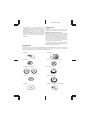
Symbols
The following show the symbols used for the tool. Be sure that you understand their meaning before use.
[ Read instruction manual.
[ DOUBLE INSULATION
[ Wear safety glasses.
4
9540 (’100. 12. 26)
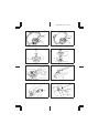
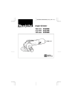
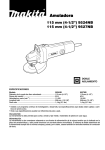
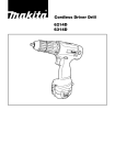
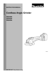
Explanation of general view
1
2
3
4
Wheel guard
Bearing box
Screw
Lock nut
5
6
7
8
Depressed center wheel
Inner flange
Spindle
Lock nut wrench
SAFETY INSTRUCTIONS
9
10
11
12
Shaft lock
Switch lever
Brush holder cap
Screwdriver
13. Don’t overreach
Keep proper footing and balance at all times.
14. Maintain tools with care
Keep tools sharp and clean for better and safer
performance. Follow instructions for lubricating
and changing accessories. Inspect tool cords
periodically and, if damaged, have repaired by
authorized service facility. Inspect extension cords
periodically and replace if damaged. Keep
handles dry, clean and free from oil and grease.
15. Disconnect tools
When not in use, before servicing, and when
changing accessories such as blades, bits and
cutters.
16. Remove adjusting keys and wrenches
Form the habit of checking to see that keys and
adjusting wrenches are removed from tool before
turning it on.
17. Avoid unintentional starting
Don’t carry plugged-in tool with finger on switch.
Be sure switch is off when plugging in.
18. Outdoor use extension cords
When tool is used outdoors, use only extension
cords intended for use outdoors and so marked.
19. Stay alert
Watch what you are doing. Use common sense.
Do not operate tool when you are tired.
20. Check damaged parts
Before further use of the tool, a guard or other part
that is damaged should be carefully checked to
determine that it will operate properly and perform
its intended function. Check for alignment of moving parts, binding of moving parts, breakage of
parts, mounting, and any other conditions that
may affect its operation. A guard or other part that
is damaged should be properly repaired or
replaced by an authorized service center unless
otherwise indicated elsewhere in this instruction
manual. Have defective switches replaced by and
authorized service center. Do not use tool if switch
does not turn it on and off.
21. Warning
The use of any other accessory or attachment
other than recommended in this operating instruction or the catalog may present a risk of personal
injury.
22. Have your tool repaired by an expert
This electric appliance is in accordance with the
relevant safety rules. Repairing of electric appliances may be carried out only by experts otherwise it may cause considerable danger for the
user.
Warning! When using electric tools, basic safety
precautions should always be followed to reduce
the risk of fire, electric shock and personal injury,
including the following.
Read all these instructions before attempting to
operate this product and save these instructions.
For safe operation:
1. Keep work area clean
Cluttered areas and benches invite injuries.
2. Consider work area environment
Don’t expose power tools to rain. Don’t use power
tools in damp or wet locations. Keep work area
well lit. Don’t use power tools in presence of
flammable liquids or gases.
3. Guard against electric shock
Prevent body contact with grounded surfaces
(e.g. pipes, radiators, ranges, refrigerators).
4. Keep children away
Do not let visitors contact tool or extension cord.
All visitors should be kept away from work area.
5. Store idle tools
When not in use, tools should be stored in dry,
high, or locked-up place, out of the reach of
children.
6. Don’t force tool
It will do the job better and safer at the rate for
which it was intended.
7. Use right tool
Don’t force small tools or attachments to do the
job of a heavy duty tool. Don’t use tools for
purposes not intended; for example, don’t use
circular saw for cutting tree limbs or logs.
8. Dress properly
Do not wear loose clothing or jewelry. They can be
caught in moving parts. Rubber gloves and nonskid footwear are recommended when working
outdoors. Wear protective hair covering to contain
long hair.
9. Use safety glasses and hearing protection
Also use face or dust mask if cutting operation is
dusty.
10. Connect dust extraction equipment
If devices are provided for the connection of dust
extraction and collection facilities, ensure these
are connected and properly used.
11. Don’t abuse cord
Never carry tool by cord or yank it to disconnect it
from receptacle. Keep cord from heat, oil and
sharp edges.
12. Secure work
Use clamps or a vise to hold work. It’s safer than
using your hand and it frees both hands to operate
tool.
5
9540 (’100. 12. 26)
ADDITIONAL SAFETY RULES
24. Do not use water or grinding lubricant.
ENB031-3
1. Always wear safety goggles and ear protectors during operation.
2. Always be sure that the tool is switched off
and unplugged before carrying out any work
on the tool.
3. Keep guards in place.
4. Use only wheels with correct size and wheels
having a maximum operating speed at least as
high as the highest No Load Speed marked on
the tool’s nameplate.When using depressed
center wheels, be sure to use only fiberglassreinforced wheels.
5. Check the wheel carefully for cracks or damage before operation. Replace cracked or
damaged wheel immediately.
6. Observe the instructions of the manufacturer
for correct mounting and use of wheels.
Handle and store wheels with care.
7. Do not use separate reducing bushings or
adaptors to adapt large hole abrasive wheels.
8. Use only flanges specified for this tool.
9. Do not damage the spindle, the flange (especially the installing surface) or the lock nut.
Damage to these parts could result in wheel
breakage.
10. For tools intended to be fitted with threaded
hole wheel, ensure that the thread in the wheel
is long enough to accept the spindle length.
11. Before using the tool on an actual workpiece,
test run the tool at the highest no load speed
for at least 30 seconds in a safe position. Stop
immediately if there is any vibration or wobbling that could indicate poor installation or a
poorly balanced wheel. Check the tool to
determine the cause.
12. Check that the workpiece is properly supported.
13. Hold the tool firmly.
14. Keep hands away from rotating parts.
15. Make sure the wheel is not contacting the
workpiece before the switch is turned on.
16. Use the specified surface of the wheel to
perform the grinding.
17. Do not use cutting off wheel for side grinding.
18. Watch out for flying sparks. Hold the tool so
that sparks fly away from you and other persons or flammable materials.
19. Pay attention that the wheel continues to
rotate after the tool is switched off.
20. Do not touch the workpiece immediately after
operation; it may be extremely hot and could
burn your skin.
21. Position the tool so that the power cord
always stays behind the tool during operation.
22. If working place is extremely hot and humid, or
badly polluted by conductive dust, use a
short-circuit breaker (30 mA) to assure operator safety.
23. Do not use the tool on any materials containing asbestos.
SAVE THESE INSTRUCTIONS.
OPERATING INSTRUCTIONS
Installing the wheel guard (Fig. 1 & 2)
Mount the wheel guard with the tab on the wheel
guard band aligned with the notch on the bearing box.
Then rotate the wheel guard 180° clockwise (for
9526NB) or counterclockwise (for 9527NB and
9528NB). Be sure to tighten the screws securely.
Installing side grip (auxiliary handle) (Fig. 3)
For 9527NB and 9528NB only
Screw the side grip on the tool securely. The side grip
can be installed on either side of the tool, whichever is
convenient.
Installing or removing depressed center
wheel
CAUTION:
Always be sure that the tool is switched off and
unplugged before installing or removing the wheel.
Mount the inner flange onto the spindle. Fit the wheel
on over the inner flange and screw the lock nut onto
the spindle. (Fig. 4)
To tighten the lock nut, press the shaft lock firmly so
that the spindle cannot revolve, then use the lock nut
wrench and securely tighten clockwise. (Fig. 5)
WARNING:
Only actuate the shaft lock when the spindle is not
moving.
Switch action (Fig. 6)
CAUTION:
Before plugging in the tool, always check to see that
the switch actuates properly and returns to the ‘‘OFF’’
position when the rear of the switch lever is
depressed.
To switch on, depress the rear of the switch lever and
push it forward. Then depress the front of the switch
lever to lock it.
To switch off, depress the rear of the switch lever.
Operation (Fig. 7)
Hold the tool firmly with both hands. Turn the tool on
and then apply the wheel or disc to the workpiece.
In general, keep the edge of the wheel or disc at an
angle of about 15° – 30° to the workpiece surface.
During the break-in period with a new wheel, do not
work the griader in the B direction or it will cut into the
workpiece. Once the edge of the wheel has been
rounded off by use, the wheel may be worked in both
A and B directions.
WARNING:
• It should never be necessary to force the tool. The
weight of the tool applies adequate pressure. Forcing and excessive pressure could cause dangerous
wheel breakage.
6
9540 (’100. 12. 26)
• Continued use of a worn-out wheel may result in
wheel explosion and serious personal injury.
Depressed center wheel should not be used after it
has been worn down to 75 mm (3!) in diameter for
Model 9526NB or 90 mm (3-1/2!) for Models
9527NB and 9528NB in diameter. Use of the wheel
after this point is unsafe and it should be removed
from service and rendered unusable by intentional
destruction.
MAINTENANCE
CAUTION:
Always be sure that the tool is switched off and
unplugged before carrying out any work on the tool.
Replacing carbon brushes (Fig. 8)
Remove and check the carbon brushes regularly.
Replace when they wear down to the limit mark. Keep
the carbon brushes clean and free to slip in the
holders. Both carbon brushes should be replaced at
the same time. Use only identical carbon brushes.
Use a screwdriver to remove the brush holder caps.
Take out the worn carbon brushes, insert the new
ones and secure the brush holder caps.
To maintain product safety and reliability, repairs,
maintenance or adjustment should be carried out by a
Makita Authorized Service Center.
ACCESSORIES
CAUTION:
These accessories or attachments are recommended for use with your Makita tool specified in this manual. The
use of any other accessories or attachments might present a risk of injury to persons. The accessories or
attachments should be used only in the proper and intended manner.
• Wheel cover
• Abrasive discs
• Inner flange
• Lock nut 10 – 30 (For abrasive disc)
• Depressed center wheels
• Wire cup brush 75
• Lock nut
• Wire bevel brush 85
• Rubber pad
• Wheel guard assembly (For cut-off wheel)
7
9540 ('100. 12. 26)
UK only
DOUBLE INSULATION
THE ADDITIONAL COMMENT OF ELECTRICAL CONNECTION
The tool is double insulated for safety, no earth connection is required.
CAUTION:
The tool must be connected to a plug having a rated current greater than that of tool.
The rated voltage and current appear on the name plate.
IMPORTANT: The wires in the mains lead are coloured in accordance with the following code.
NOTE:
As the colours of the mains lead of the tool may not correspond with the coloured markings
identifying the terminals in your plug, proceed as follows:
THE WIRE WHICH IS COLOURED BLUE MUST BE CONNECTED TO THE TERMINAL
WHICH IS MARKED WITH THE LETTER ``N'' OR COLOURED BLACK. THE WIRE WHICH IS
COLOURED BROWN MUST BE CONNECTED TO THE TERMINAL WHICH IS MARKED WITH
THE LETTER ``L'' OR COLOURED RED.
CAUTION:
Neither wire is to be connected to earth terminal which is marked with the letter ``E'' or symbol
`` ''.
FOR 110 VOLT TOOL, USE PLUGS TO BS4343.
Made in Japan
883877A6