1
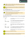
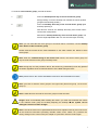
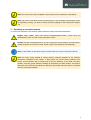
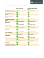
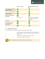
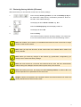
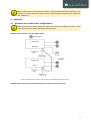
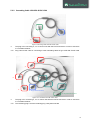
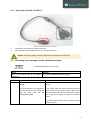
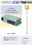
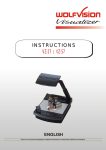
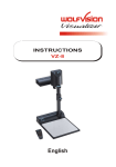
liECO+
Firmware-Version 1.1
Document Rev0
User Manual
Cascading of
motor control units
www.kesseboehmer-ergonomietechnik.de
Contents
1
2
3
4
5
6
Definition of Cascading ......................................................................................................................... 3
1.1
Master .......................................................................................................................................... 3
1.2
Slave ............................................................................................................................................ 3
1.3
Single Mode ................................................................................................................................. 3
1.4
Single control unit ......................................................................................................................... 3
Commissioning ..................................................................................................................................... 4
2.1
Components required ................................................................................................................... 4
2.2
Connecting motors ....................................................................................................................... 4
2.2.1 Configuration with only one motor group ................................................................................. 4
2.2.2 Configuration with two motor groups ....................................................................................... 4
2.3
Connecting the handswitch .......................................................................................................... 5
2.4
Connecting the cascading cable .................................................................................................. 5
2.5
Connecting the power cords ........................................................................................................ 6
2.6
Initial reset for the motors............................................................................................................. 6
Operating a cascaded network ............................................................................................................. 8
3.1
Changing the network ................................................................................................................ 10
3.2
Restoring factory defaults (S0 menu) ........................................................................................ 11
Collision protection.............................................................................................................................. 12
Appendix ............................................................................................................................................. 13
5.1
Examples of possible motor configurations ............................................................................... 13
5.2
Pictures ...................................................................................................................................... 17
5.2.1 Cascading Cable LOG-CBL-SYNC-500 ................................................................................ 17
5.2.2 Cascading Cable LOG-CBL-SYNC-1500 .............................................................................. 18
5.2.3 Split cable LOG-CBL-LC-DATA-Y ......................................................................................... 19
5.3
Cascading error messages on the handswitch display .............................................................. 19
Further information.............................................................................................................................. 20
6.1
Technical data ............................................................................................................................ 20
6.2
Optional products ....................................................................................................................... 20
6.3
Manufacturer .............................................................................................................................. 20
2
1
Definition of Cascading
Cascading enables you to operate up to 12 motors synchronously by connecting up to four control units.
This User Manual describes the functions in such a system.
1.1
Master
In a cascaded system, the control unit that the handswitch is connected to is the master. This control unit
is the only one in the entire network to accept input from the handswitch and therefore plays the most
important role.
1.2
Slave
Slaves are control units serving to expand the master and are connected to the master with special
cascade cables. Do not connect any handswitches to these control units.
Note: the cascaded network will not accept handswitch input if the handswitch is connected
to a slave.
Note: a cascaded network consisting of two to four control units is to be regarded as a
closed system. (Example: if there are instructions in the manual to disconnect the power
supply, do so for all the control units in the network. It means that all the control units should
be in a de-energized state at the same time.)
1.3
Single Mode
When a control unit is in single mode, the cascading function is active, but it is operated as a single
control unit only.
Note: as long as a control unit is still at the factory settings, it is not defined as a master or
slave. It is the first keystroke that decides whether and which control unit will operate as
master and slave (see chapter 2.3) or whether it is a single control unit.
Note: you can restore the factory settings by re-parameterizing the control unit or using the
S0 menu (see chapter 3.2).
1.4
Single control unit
If a control unit is not parameterized for cascading, it can only be used as single control unit.
3
2
Commissioning
Note: if the system is to function correctly, we strongly recommend following these
instructions step by step, otherwise serious complications may arise.
Note: to make sure that the control unit is suitable for the planned cascading network, find
and check the control unit parameters in ConfigTool.
Note: do not connect a control unit that is not at the factory settings.
2.1
Components required
To create a fully functioning network, you will require the following components:
Network with 2 control units
Network with 3 control units
Network with 4 control units
1 comfort handswitch
1 comfort handswitch
1 comfort handswitch
2 liECO+
3 liECO+
4 liECO+
2 power cords
3 power cords
4 power cords
1 cascading cable
3 cascading cables
4 cascading cables
LOG-CBL-SYNC-500
LOG-CBL-SYNC-1500
LOG-CBL-SYNC-1500
up to 6 drives
up to 9 drives
up to 12 drives
Note: for drives with one single hall sensor, it is only possible to set up a network with 2
control units.
Note: you will find information on the various cascade cables in chapter 5.2.
2.2
Connecting motors
Here you have to decide whether you wish to use one or two motor groups in your system.
2.2.1
Configuration with only one motor group
If the overall system only has one motor group, the motors can be allocated to the control units as
required (provided that they have been parameterized).
2.2.2
Configuration with two motor groups
If the overall system has two motor groups, you have to connect the motors to the relevant control unit as
defined in the configuration.
Note: when using two motor groups, always observe the motor configurations for the control
units used.
Note: chapter 5.1 shows examples of possible motor configurations.
4
2.3
Connecting the handswitch
If you only intend to use one motor group in the system, you can plug the handswitch into the 7-pin
handswitch socket (HS) on any control unit that is to act as the master during operation.
When using two motor groups, you have to connect the handswitch to a control unit that uses both motor
groups.
Note: when connecting the handswitch, take the motor configuration used in the network into
consideration.
Note: Kesseböhmer Ergonomietechnik recommends using a comfort handswitch with
display and MEMO function for cascading.
Note: chapter 5.1 shows examples of possible motor configurations.
Note: when a control unit is still at factory settings and a key is pressed on a handswitch for
the first time, it is declared to be the master. This is why the handswitch may only be plugged
into the appropriate control unit.
Note: it is not possible to use more than one handswitch in the network, as only the master
can accept handswitch input.
2.4
Connecting the cascading cable
To enable operation in a network, plug your control units into the DATA-Connector using the cascade
cable.
In addition, you can also connect an external sensor with the LOG-CBL-LC-DATA-Y distribution cable
(see chapter 4).
Note: if you wish to operate three or four control units, use the LOG-CBL-SYNC-1500 cable.
Note: to operate two control units, you can use the LOG-CBL-SYNC-500 cable.
Note: you will find information on the various cascade cables in chapter 5.2.
Note: in chapter 5.1 you will find examples of possible networks and the components to be
used.
5
Danger: if you connect a cascade cable to a single control unit, the control unit will
misinterpret it and the collision protection settings can subsequently be affected. As a result,
never use a cascade cable in single mode.
Note: to ensure that operation is as reliable as possible, we recommend making sure when
installing the cascade cables that they are not subjected to any mechanical loading (e.g.
twisting).
2.5
Connecting the power cords
Before you supply power to all the control units, check that you have performed all the previous steps
correctly and your network basically corresponds to the one shown in chapter 5.1.
Caution: before your plug in the power cords, check again that
2.6
•
The mains voltage is suitable for your control unit as indicated on the nameplate
•
All the components are plugged into the correct sockets
Initial reset for the motors
After you have connected the control units to the power supply for the first time, you have to reset the
motors once, as the network is also addressed at the same time. To reset the first motor group,
proceed as follows:
Press the S key for more than 5 seconds, if you have a handswitch
with memory function.
1.
resp.
Press the desktop down and desktop up simultaneously for 5
seconds if you have a handswitch without memory function.
and
Thus you start the reset mode of the control unit.
Press the S key, if you have a handswitch with memory function.
Keep the button pressed until the desktop reaches its reset
position.
2.
resp.
and
3.
Press the desktop down and desktop up simultaneously if you
have a handswitch without memory function. Keep the buttons
pressed until the desktop reaches its reset position.
Release the button(s). The electric height-adjustable desk can now
be used again normally.
Note: this function is only available for motor group 1!
Note: during step 2 of the procedure above, the shown key (combination) must stay pressed
the whole regardless of the movement direction of the table during the reset.
6
To reset the second motor group, proceed as follows.
1.
Press the desktop down key of the second motor group.
Keep pressing it until the desktop has reached the lowest position
(programmed desktop position).
2.
Press the desktop down key of the second motor group again
and keep pressing it.
After about 5 seconds, the desktop will slowly move further until it
reaches the reset position.
3.
Release the desktop down key of the second motor group. The
electric height-adjustable desk can now be used again normally.
Note: you can reset the first motor group too as shown above. Therefore, use the desktop
down button of the first motor group.
Please read the manual of the used handswitch to see which buttons are linked to which
motor group!
Note: when the commissioning of the control unit is done, the second motor group can
only be reset if the first motor group is already reset!
Note: during step 2 of the procedure above, the shown key (combination) must stay pressed
the whole regardless of the movement direction of the table during the reset.
Note: please refer to the comfort handswitch manual for other handswitch functions.
Note: you have to reset the motor groups in the right order (first motor group 1, then motor
group 2).
Note: it takes about 5 seconds for the motor groups to start the reset.
Danger: while or immediately after resetting the motors, you must check whether the motors
in the relevant motor group are actually adjusting the desktop
the system can be
damaged if it does not start straight.
Note: if not all the motors to be parameterized have been adjusted correctly, first of all check
all the electrical connections (including cascade cables, motor cables, etc.). Restore the
factory settings on the control units (see chapter 3.2) and then reset the motors again.
7
Note: the reset must be fully completed, as the system will not otherwise be operational.
Note: if an error occurs while a motor is being reset (i.e. error message on the display, motor
not operating correctly), you have to restore the factory settings on the network (see chapter
3.2).
3
Operating a cascaded network
To ensure safe operation of the network, please follow the safety instructions listed below:
Danger: keep children away from electric height-adjustable desks, control units and
handswitches. There is a risk of injury and electric shock.
Caution: if there is a thunderstorm or you do not intend to use the desk for a longer period,
unplug the power cord from the socket. Power surges could otherwise cause damage.
Note: for information on the basic functions, please refer to the user manual of the liECO+.
Note: the motor group capable of saving memory positions depends on the software
parameters configured for the liECO+. If both groups can store memory positions, both
groups’ current positions will be saved (even if they are different). If you recall a memory
position, the motor groups adjust the desktop to the position one after another. This means
that first the first motor group adjusts the desktop to the position and only when it is reached
does the second group adjust.
8
The following features are available in the different operating modes:
Maximum number of drives
Single control unit
Cascaded network or single
mode
3 (liECO+)
Up to 12 (4x liECO+)
(for both motor groups)
(for both motor groups)
(for both motor groups)
(for both motor groups)
(for both motor groups)
(for both motor groups)
(for both motor groups)
(for both motor groups)
(for both motor groups)
(for both motor groups)
(for motor group 1)
(for motor group 1)
(for both motor groups)
(for both motor groups)
(for motor group 1)
(for motor group 1)
Movement of one motor group
Movement of two motor
groups
Save and recall memo
positions
Change displayed desktop
height
Manual reset
Low Speed Area
Safety Area
Virtual end-switches
Plug Detection
Auto Detect Number of Drives
Duty cycle
Change displayed desktop
position (cm or inch, S5-Menu)
9
Single control unit
Cascaded network or single
mode
2 per control unit
1 per control unit in cascaded
network or 2 per control unit in
Single-Mode
Reset control unit to factory
settings (S0-Menu)
Electronic collision protection
Collision protection with leg
integrated sensors
Collision protection with
squeeze line
Drive back
Error messages on the
handswitch display
Click codes
3.1
Changing the network
If you need to replace one or more control units in a network, proceed as follows:
1.
Before you start to replace any control unit with new ones, reset all
the control units in the planned network to factory settings (see
chapter 3.2).
2.
Disconnect the entire network from the mains power.
3.
Create the new network (see chapter 2)
Note: do not connect a control unit that is not at the factory settings.
10
3.2
Restoring factory defaults (S0 menu)
With this function you can reset the control unit to its factory settings.
1.
Press the keys memory position 1, 2 and the desktop up key at
the same time. Keep the key combination pressed for about 10
seconds. Then release the keys.
The display will show S and a number, e.g. S 5.
2.
Press the desktop up key until the display reads S 0.
The display will show S 0.
3.
Press the S key.
The control unit will be reset to its factory settings. The control unit
is now in the same state as it is when the commissioning is done.
Note: this enables you to break up a cascaded network and use each control unit in single
mode or create a new network.
Note: when you open the S0 menu, all the control units in the network will be reset to the
factory defaults.
Note: before you make any changes to the network (e.g. parameters, configuration), you
always have to restore the factory settings.
Note: the menu timeout is 5 seconds, this means that the menu will close automatically
without storing new settings if the user does not press a key for 5 seconds.
Note: after starting the menu, the display will read S and any number, for instance S 5. The
number depends on the parameters of the control unit.
Danger: if drives are replaced in the cascaded network, the network needs to be reset to the
factory defaults and the drives must be reset.
11
4
Collision protection
Besides the integrated collision protection, also squeeze lines can be used in a cascaded network.
These sensors must be connected to the control unit(s) using the split cable LOG-CBL-LC-DATA-Y on
the DATA-connector.
Danger: in spite of electronic collision protection being in place, there may still be a risk of
pinching in exceptional cases, as it is not only the control unit, but also the interaction
between the mechanical and electronic systems that is responsible for cutting out the motor.
In addition, the mechanical components, motor and ambient conditions all affect cut-out
sensitivity.
As the control unit manufacturer, Kesseböhmer Ergonomietechnik cannot therefore eliminate
this residual risk completely or accept any liability.
Note: the sensitivity and the cutoff value of the electronic collision protection depend on the
whole system (mechanical and electrical components). To evaluate the capability of a height
adjustable table, please contact Kesseböhmer Ergonomietechnik!
Note: if you use external safety sensors in connection with cascading, please note that only
one sensor per control unit is supported.
Note: you can however combine several different types of sensors in the network. Ensure
that control unit parameterization is suitable for the sensor connected.
Note: external sensors must be activated by parameters.
Note: when control units are only parameterized for the second motor group, do not connect
and parameterize any safety features (e.g. electronic collision protection, sensors).
Note: if you use external sensors in a cascaded network, one sensor must be connected to
the master. Do not plug external sensors into slave control units only.
Note: a control unit has not detected the sensor until it has acknowledged the fact with two
clicks. After resetting the motor, always wait for confirmation that the sensor has been
detected.
Note: chapter 5.1 gives examples of how external sensors are to be used in the network.
Note: you will find information on the split cable LOG-CBL-LC-DATA-Y in chapter 5.2.3.
12
Note: To disconnect a sensor from the system, it must be deactivated in the control unit. The
first step is to unplug the sensor and the next to restore the factory settings on the control unit
(see chapter 3.2).
5
5.1
Appendix
Examples of possible motor configurations
Note: As soon as two motor groups are used in the network, the master must be a control
unit to which motors in both motor groups are connected.
Network with 4 motors in the first motor group
Figure 1: Network with four motors in the first motor group, optionally with external sensors
Network with 3 motors in the first and one motor in the second motor group
13
Figure 2: Network with three motors in the first and one motor in the second motor group, optionally with external sensors
14
Network with 4 motors in the first and one motor in the second motor group
Figure 3: Network with four motors in the first and one motor in the second motor group, optionally with external sensors
Network with 2 motors in the first and 2 motors in the second motor group
Figure 4: Network with two motors in the first and two motors in the second motor group, optionally with external sensors
15
Network with 3 motors in the first and 2 motors in the second motor group
Figure 5: Network with three motors in the first and two motors in the second motor group, optionally with external sensors
Network with 6 motors in the first and 3 motors in the second motor group
Figure 6: Network with six motors in the first and three motors in the second motor group, optionally with external sensors
16
Network with 8 motors in the first and 4 motors in the second motor group
Figure 7: Network with eight motors in the first and four motors in the second motor group, optionally with external sensors
5.2
5.2.1
Pictures
Cascading Cable LOG-CBL-SYNC-500
Figure 8: Cascading cable LOG-CBL-SYNC-500
The plugs are for connecting two control units with the DATA-Connector in order to use them in
a cascaded network.
17
5.2.2
Cascading Cable LOG-CBL-SYNC-1500
Figure 9: Cascading cable LOG-CBL-SYNC-1500
/
The plug is for connecting 2, 3 or 4 control units with the DATA-Connector in order to use them
in a cascaded network.
Plug 2 and socket 3 are for connecting to other cascading cables of type LOG-CBL-SYNC-1500
stays disconnected
stays disconnected
Figure 10: 4 connected LOG-CBL-SYNC-1500
/
The plug is for connecting 2, 3 or 4 control units with the DATA-connector in order to use them
in a cascaded network.
The remaining plug 2 and the remaining plug 3 stay disconnected
18
5.2.3
Split cable LOG-CBL-LC-DATA-Y
Figure 11: Split cable LOG-CBL-LC-DATA-Y
This plug is connected to the DATA-connector
Both cascade cable and safety sensor can be connected here
Caution: do not ever plug a cascade cable into both sockets at the same time.
5.3
Cascading error messages on the handswitch display
The display reads E + an error code.
Cause
There is an internal fault in the liECO+
control unit.
Number
93
Remedy
Proceed as indicated in the following list.
Description
Remedy
Connection error in the cascaded Check all the cable connections and try to reset the
network
motors.
(The error appears on the display for
15 seconds and then the control unit
goes into reset mode with the
display flashing 000)
If you cannot reset the motors, disconnect all the
control units from the power supply. Wait for at
least 5 seconds and then reconnect all the control
units to the power supply. Try again to reset the
motors.
If you still cannot reset the motors, please contact
customer service.
19
Note: you will find a complete list of error messages in the appendix of the liECO+ User
Manual.
Important: if the remedy involves connecting and disconnecting a control unit (which is the
same as switching it on and off), do so for all the control units in the cascaded network. It
means that all the control units should be in a de-energized state at the same time.
Note: if not all the control units are on standby when the power supply to at least one control
unit is disconnected, it will be interpreted as connection error E93.
Note: if the mains power breaks down or is disconnected from the control unit during
movement of the drives, a manual reset might be necessary.
6
6.1
Further information
Technical data
Note: you can find the technical data of your control unit in the appropriate datasheet.
6.2
Optional products
Note: information about available optional products can be found in the latest product
catalogue and on the website www.kesseboehmer-ergonomietechnik.com
6.3
Manufacturer
LOGICDATA
Electronic & Software Entwicklungs GmbH
Wirtschaftspark 18
A-8530 Deutschlandsberg - Austria
Tel.:
Fax:
Email:
URL:
+43 (0)3462 5198 0
+43 (0)3462 5198 530
[email protected]
www.logicdata.at
20