1
Table of Contents
Chapter 1 - Introduction
1.1
Introduction.............................................................................................. - 1 1.2
Definition of terms.................................................................................... - 1 1.3
Background ............................................................................................. - 1 1.4
Goal statement ........................................................................................ - 1 1.5
Objectives................................................................................................ - 2 1.6
Project management technique ............................................................... - 2 1.7
Stages of development ............................................................................ - 2 1.8
Work plan ................................................................................................ - 3 1.9
Technologies overview ............................................................................ - 3 Chapter 2 - User requirements and analysis
2.1
Introduction.............................................................................................. - 5 2.2
Background ............................................................................................. - 5 2.2.1
Current procedure ............................................................................ - 5 2.2.2
Current problems.............................................................................. - 6 2.2.3
The users ......................................................................................... - 7 2.3
User requirements ................................................................................... - 7 2.3.1
Desired working practice .................................................................. - 7 2.3.2
Requirements capture ...................................................................... - 8 2.3.3
Users requirements .......................................................................... - 9 2.3.4
Differing user requirements ............................................................ - 10 Chapter 3 - Specification and design
3.1
Introduction............................................................................................ - 11 3.2
Research ............................................................................................... - 11 3.2.1
Automated Deployment Services (ADS) vs. Remote Installation
Services (RIS) features................................................................................. - 11 3.2.2
ADS vs. Novell ZENworkes 6 and Altiris SPS ................................ - 12 3.2.3
Speed of deployment...................................................................... - 13 3.2.4
Cost of deployment......................................................................... - 13 3.2.5
Advantages of C# ........................................................................... - 13 3.2.6
Advantages of Visual Studio........................................................... - 14 3.2.7
Other project tools .......................................................................... - 14 3.3
Risk assessment summery.................................................................... - 14 Chapter 4 - Research and risk assessment
4.1
Introduction............................................................................................ - 15 4.2
Specification .......................................................................................... - 15 4.2.1
Functional specification .................................................................. - 15 4.2.2
Non-functional specification............................................................ - 16 4.3
Website design ...................................................................................... - 17 4.3.1
HCI principles ................................................................................. - 17 4.3.2
Design choice and justification ....................................................... - 19 4.4
Data modelling....................................................................................... - 21 4.4.1
Current database............................................................................ - 21 4.4.2
Identify entities and attributes ......................................................... - 21 -
- iii -
4.5
4.6
4.7
Entity relationship identification ............................................................. - 23 Normalization......................................................................................... - 25 Data Dictionary ...................................................................................... - 26 -
Chapter 5 - Implementation
5.1
Introduction............................................................................................ - 29 5.2
Website map.......................................................................................... - 29 5.3
Database creation ................................................................................. - 30 5.4
Login page............................................................................................. - 30 5.5
Left Navigation page.............................................................................. - 31 5.6
Home page ............................................................................................ - 31 5.7
Configuration page ................................................................................ - 32 5.7.1
Loading of a configuration .............................................................. - 32 5.7.2
Saving of a Configuration ............................................................... - 33 5.7.3
Applying a configuration ................................................................. - 35 5.8
View configuration pages....................................................................... - 38 5.9
Administration page ............................................................................... - 39 5.10 Manage users, tasks and computers pages .......................................... - 39 5.11 Statistics page ....................................................................................... - 40 5.12 Style sheet............................................................................................. - 40 Chapter 6 - Testing and evaluation
6.1
Introduction............................................................................................ - 41 6.2
Testing outline ....................................................................................... - 41 6.2.1
Unit testing outline .......................................................................... - 41 6.2.2
Integration testing outline ............................................................... - 41 6.2.3
Acceptance testing outline.............................................................. - 42 6.3
Unit testing............................................................................................. - 42 6.4
Integration testing .................................................................................. - 43 6.4.1
Test cases ...................................................................................... - 43 6.4.2
Security testing ............................................................................... - 43 6.5
Acceptance testing ................................................................................ - 44 6.5.1
Usability testing .............................................................................. - 44 6.5.2
System testing ................................................................................ - 44 6.5.3
Functional testing ........................................................................... - 45 6.6
Evaluation and testing summery............................................................ - 46 Chapter 7 - Conclusion and future developments
7.1
Introduction............................................................................................ - 47 7.2
Project summary.................................................................................... - 47 7.3
Critique .................................................................................................. - 47 7.4
Project extensions ................................................................................. - 48 7.5
Conclusion............................................................................................. - 49 References and bibliography ............................................................................- 50 Appendix ...........................................................................................................- 54 User Manual …………………………………………………………………………-154 -
- iv -
List of Tables
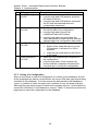
Table 1.1: Terms used throughout the report
Table 1.2: Project objectives
Table 2.1: Advantages and Disadvantages of RIS
Table 2.2: Advantages and Disadvantages of ADS
Table 2.3: ILS problems generalised
Table 2.4: Identified users of the website
Table 2.5: Advantages and Disadvantages of new website
Table 2.6: Users primary requirements
Table 2.7: Users secondary requirements
Table 3.1: Difference of ADS and RIS
Table 3.2: Benefits of C#
Table 3.3: Benefits of Visual Studio
Table 3.4: Other project tools
Table 4.1: Functional specification
Table 4.2: Non-functional specification
Table 4.3: Semiotics in use
Table 4.4: Websites defensive design methods
Table 4.5: Web pages security methods
Table 4.6: Colours used on the website
Table 4.7: Identified database entities
Table 4.8: Extended entities from current ADS
Table 4.9: Description of relationship terms
Table 4.10: Final USER table
Table 4.11: Final TASK table
Table 4.12: Final COMPUTER table
Table 4.13: Final JOB table
Table 4.14: Final CONFIGURATION table
Table 4.15: Final JOBTASK table
Table 4.16: Final CONFIGURATIONJOB table
Table 5.1: Steps taken to load a configuration
Table 5.2: Steps taken to save a configuration
Table 5.3: Step taken to apply a configuration
Table 5.4: User attribute row numbers
Table 6.1: Types of unit testing performed on the website
Table 6.2: Types of integration testing performed on the website
Table 6.3: Types of acceptance testing performed on the website
Table 6.4: Web pages that passed all unit tests
Table 6.5: Web pages that did not pass all unit tests
Table 6.6: Levels of page security
Table 6.7: Security levels of the web pages
Table 6.8: How well the user requirements were met
Table 6.9: How well the functional specification was met
Table 6.10: How well the non-functional specification was met
-v-
-1-2-5-6-6-7-7-9-9- 11 - 13 - 14 - 14 - 15 - 16 - 17 - 18 - 18 - 19 - 21 - 21 - 23 - 26 - 27 - 27 - 28 - 28 - 28 - 28 - 33 - 34 - 36 - 39 - 41 - 41 - 42 - 42 - 42 - 43 - 43 - 44 - 45 - 45 -
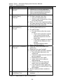
List of Figures
Figure 3.1: Deployment system scores
Figure 3.2: Deployment system features
Figure 4.1: Defensive design
Figure 4.2: Screenshot of Microsoft’s website
Figure 4.3: New task hierarchy using extended entities
Figure 4.4: USER and JOB relationship
Figure 4.5: USER and CONFIGURATION relationship
Figure 4.6: CONFIGURATION and JOB relationship
Figure 4.7: JOB and TASK relationship
Figure 4.8: JOB and COMPUTER relationship
Figure 4.9: Complete entity relationship diagram
Figure 4.10: JOBTASK discovered entity
Figure 4.11: CONFIGURATIONJOB discovered entity
Figure 4.12: Final entity relationship diagram
Figure 4.13: ADS and website database link
Figure 5.1: Website map
Figure 5.2: Joining of XML tasks
Figure 5.3: Flow diagram for applying a configuration
Figure 7.1: Linear and non-linear configurations
- 12 - 12 - 18 - 20 - 22 - 24 - 24 - 24 - 24 - 24 - 25 - 25 - 25 - 26 - 27 - 29 - 35 - 37 - 48 -
List of Extracts
Extract 5.1: Code to create a connection to the website database
Extract 5.2: Data being formatted as a SQL data type
Extract 5.3: Method to retrieve user information
Extract 5.4: SQL statement joining database tables
Extract 5.5: Code to check the user’s privileges
- vi -
- 30 - 30 - 31 - 32 - 38 -
Andrew Turner – Automated Deployment Services Website
Chapter 1 – Introduction
Chapter 1
Introduction
1.1
Introduction
This project is concerned with assisting data centre workers and system
administrators with the modelling, maintenance and deployment of data centre
servers and desktop machines. The system produced will help technicians to
quickly and easily analyse the current setup of their computers, and return those
computers back to their original state or allow the installation of additional software
remotely. This functionally will reduce the amount of time they must spend
maintaining computer systems and the amount of time it will take them to return
their systems to an operational state following a catastrophic event.
1.2
Definition of terms
To help clarify the subjects of discussion in this report, the terms in Table 1.1 will
be used consistently throughout. A Glossary of Terms can also be found in
Appendix 1.1
ILS Team
Members of staff working for the Microsoft UK Infrastructure
and Laboratory Support (ILS) team
Computer Refers to any desktop or server computer system
User
Any person who uses the website
Customer A person who is paying for the use of the ILS labs
Technician A person who is responsible for the computers’ maintenance,
including data centre workers and system administrators
Table 1.1: Terms used throughout the report
1.3
Background
This project is a result of an investigation into the working practices of the
Infrastructure and Laboratory Support (ILS) team at Microsoft UK. The ILS team is
responsible for the deployment and maintenance of an 800-machine computer
laboratory. The Laboratory is used by internal and external customers for testing
purposes, typically for a one or two week period. During their daily work the ILS
team must ensure that customers’ machines have the correct software installed
and must build specific system setups for them.
This project found the current problems facing Microsoft ILS team and produced a
suitable solution to solve these problems. In addition to a computer program this
project includes research into new technologies, procedures and new working
practices.
1.4
Goal statement
To deliver a system that will allow technicians to easily maintain and model their
computer data centres, and allow them to quickly and easily rebuild their data
centre from a bare bones situation.
-1-
Andrew Turner – Automated Deployment Services Website
Chapter 1 – Introduction
1.5
Objectives
To help successfully achieve the goal of this project a set of objectives was
created, shown in Table 1.2.
Objectives
Find the current main problems facing data centre workers and system
administrators
Research the technologies and feasibility of a solution
Design and Develop a system to solve the discovered problems
Test the system for stability, reliability and usability
Evaluate the system against the original discovered problems
Produce complete documentation for the system
Table 1.2: Project objectives
1.6
Project management technique
As creating any piece of software requires planning to produce a high quality and
functional piece of software that meets the users’ requirements, this project will
follow the V process model, shown in Appendix 1.3.
The V process model originally derived from the classic waterfall model for
software project management, shown in Appendix 1.4. This model ensures that
each stage of the project is completed successfully, and allows the flexibility to go
back and change prior parts of the project if new information is discovered later on.
It also helps with the testing of software as it shows what testing should be done at
each stage to best meet the users’ requirements.
(Dawson, 2004)
The V process model fits this project well due to the research and learning that
was required. As new information was discovered during the research stage, the
final solution better fitted the users’ needs as this information was used as part of
the solution. For these reasons the V process model was chosen over the waterfall
model.
1.7
Stages of development
As with any large project time must be managed well, to ensure efficient time
management the project was split into the following sections.
•
Introduction and planning stage – a brief introduction about the project
and the initial work plan.
•
Requirements and research - concerned with the users’ requirements for
the system and research into technologies and techniques used in the
solution.
•
Specification and design - concerned with converting the users’
requirements and suggestions into a formal specification, and designing a
solution by combining the specification with the results of the research. This
includes the design of database tables, entity relationship diagrams, data
-2-
Andrew Turner – Automated Deployment Services Website
Chapter 1 – Introduction
flow diagrams, sample user interface designs and trade offs that were made
at the design stage.
•
Implementation and testing - is concerned with the programming and
creation of additional files needed in order for the proposed system to work
and the trade offs that had to be made during the creation of the system.
•
Testing and evaluation - concerned with how the system meets the users’
requirements, and how well it matched the original specification. In addition
to the trade offs that were included in the design and implementation part of
the project, this section covers additional trade offs made. The testing
ensured the stability, functionality and usability of the system.
•
Conclusion and further developments - discuss problems encountered
during the project and the over all effectiveness of the project and possible
future developments for the system
1.8
Work plan
To help the time management of the project a Gantt chart was produced to give a
time frame for each section of the project, shown in Appendix 1.5, a revised and
easier to read Gantt chart was also produced, shown in Appendix 1.6. This gave a
clear indication of when each section of the project needed to be completed to
finish the project on time.
1.9
Technologies overview
The following are brief overviews of the technologies used in this project.
Microsoft Automated Deployment Services (ADS)
Microsoft Automated Deployment Services (ADS) is a new Microsoft service that
runs on Microsoft Windows Server 2003 Enterprise Edition to aid with the
deployment of Microsoft server operating systems. ADS can be used in data
centres to deploy software and to manage computers. ADS works by using the
Pre-boot eXecutable Environment (PXE) to allow control of computers prior to the
Operating System (OS) loading (pre-OS), and a small program called the
‘Administration Agent’ (AA) to control them post-OS. Further information on ADS is
covered in Appendix A1.2.
(Microsoft, 2005)
.NET
“Microsoft® .NET is a set of new software technologies for connecting information,
people, systems, and devices which is based on Web services—small buildingblock applications that can connect to each other as well as to other, larger
applications over the Internet.”
(Microsoft, 2005)
.NET is a Microsoft system that allows applications to easily communicate with
each other by using .NET technologies. This usually consists of using a .NET
programming language such as C#.net, VB.net or J#.net and using eXtensible
Markup Language (XML) as a common information transportation language.
-3-
Andrew Turner – Automated Deployment Services Website
Chapter 1 – Introduction
Windows Management Instrumentation (WMI)
“Windows Management Instrumentation (WMI) is a component of the
Microsoft Windows operating system and is the Microsoft implementation of WebBased Enterprise Management (WBEM), which is an industry initiative to develop
a standard technology for accessing management information in an enterprise
environment. WMI uses the Common Information Model (CIM) industry standard
to represent systems, applications, networks, devices, and other managed
components. You can use WMI to automate administrative tasks in an enterprise
environment.”
(Microsoft, 2005)
WMI can be thought of, on the most basic level, as an interface standard that
allows applications to programmatically access each others functionality and
information. This allows applications to send and receive information to each other
easily, without the programmer having to worry about the format in which the
information should be sent. The last sentence of Microsoft’s description is very apt
as this project is concerned with this area.
-4-
Andrew Turner – Automated Deployment Services Website
Chapter 2 – User requirements and analysis
Chapter 2
User requirements and analysis
2.1
Introduction
This chapter covers the identification of the problems that forms the basis of this
project, requirements of the potential users of the website and current and new
work procedures.
2.2
Background
As described in the first chapter, this project is a result of an investigation into the
working practices of the Infrastructure and Laboratory support (ILS) team at
Microsoft UK. The following section is further background information.
2.2.1 Current procedure
To help the ILS team do their job they currently have a Microsoft Remote
Installation Services (RIS) server running in the lab. More information on RIS can
be found in Appendix A2.1.
As RIS is a ‘pull’ deployment system, the laboratory technician must manually go
to each computer that requires a new OS to be installed and manually reboot it.
Once the OS has been installed, the technician must perform any post-OS
configuration required on each computer separately
The current work process that the ILS team uses is shown in Appendix 2.2 and the
times for each of these steps can be found in appendix A2.3. This process has six
steps that require interaction from the technician and requires on average a total of
5.7 minutes of their time, shown in Appendix 2.4. The total average time taken to
install an OS for one computer is 41.3 minutes.
Table 2.1 shows the advantages and disadvantages of the current system that the
ILS team have in place and Table 2.2 shows the advantages and disadvantages of
the system if the RIS server was changed to an ADS server (without additional
website functionality).
Advantage
Faster than using CD
Advantage
Standardised installations
Disadvantage Still takes a long time to install operating system
Disadvantage Requires lots technician interaction
Disadvantage Can only install single instances
Disadvantage Cannot install applications
Disadvantage Customers cannot start installation instances
Disadvantage Does not understand infrastructure hierarchy
Table 2.1: Advantages and Disadvantages of RIS
-5-
Andrew Turner – Automated Deployment Services Website
Chapter 2 – User requirements and analysis
Advantage
Faster than using RIS
Advantage
Standardised installs
Advantage
Single point of administration
Advantage
Can install applications
Disadvantage Customers cannot start installation instances
Disadvantage Does not understand infrastructure hierarchy
Disadvantage Job will not continue if one step fails
Disadvantage Potential security risks
Disadvantage Does not understand infrastructure hierarchy
Table 2.2: Advantages and Disadvantages of ADS
Although changing the RIS server for an ADS server would introduce benefits for
the ILS team, there would still be a number of disadvantages present.
The management team for ILS do not currently have an automated system for
calculating the statistics about software usage; they rely on asking the technicians
what they have installed. This is not only time consuming for both the
management and the technicians but is also not a very accurate way of collecting
the data.
2.2.2 Current problems
The main problems that face the ILS team are the design and deployment time of
complete systems. On average, a customer will ask for around 40 computers that
may all have their own unique configuration of software and hardware. This leads
to a problem with the system design, as RIS does not have the ability to store a list
of which OSs have been installed on each computer. Therefore the technician
must ensure that records are kept. Deployment time is also an issue, as the
technician has to wait for the current customers to leave on Friday before
reconfiguring the computers for the new customers arriving on Monday morning.
Although these are problems specific to the ILS team at Microsoft, they can be
generalised to apply to any organisation that has computers, shown in Table 2.3
Problem
System design
Description
This is a problem in any organisation, as all the
technicians need to know what software is on each
computer so that they do not reformat the wrong one. In
addition, as there may be many computing staff, there
needs to be a record of what software is on each
computer in case it needs to be rebuilt and the person
who built it originally is not available.
Deployment time This is becoming increasingly more important for
companies as a high computer utilisation rate will
increase profitability, for example e-commerce sites or
online services. Additionally, following a virus or hacker
attack, every minute that the computer system is down
could be costing the company thousands of pounds in
lost revenue, so restoring the computer system to its
original state quickly is imperative to minimise losses.
Table 2.3: ILS problems generalised
-6-
Andrew Turner – Automated Deployment Services Website
Chapter 2 – User requirements and analysis
2.2.3 The users
There are three main user groups identified that will use the website; these are
shown in Table 2.4.
User Group
Technical lab workers
Description
The Microsoft ILS lab team will be the primary
users of the website. The lab staff will use the
website on a daily basis to install and configure
software on computers in the Microsoft data centre.
Management
The ILS management will be the secondary users
of the website. They will use the website to retrieve
statistics about computer and software usage.
External Customers
Customers that come in to Microsoft to use the
computers in the data centre will be the tertiary
users of the website. They will use the website to
examine their current configuration and request
changes to it.
Table 2.4: Identified users of the website
2.3
User requirements
2.3.1 Desired working practice
As show in Appendix 2.2, the current working practice of the ILS team requires the
technician to go to each computer that needs a software change, and manually
perform any post-OS configuration on an individual basis.
The new working practice requested is for the technician to have much less
interaction with each computer, and for the customer to be able to submit an
electronic request as opposed to a verbal request. As new working practice,
shown in Appendix 2.5, requires less interaction from the technician it will allow
him/her to carry on with other work and also reduces the total amount of time
taken for the customers’ computers to be reconfigured.
Table 2.5 shows the advantages and disadvantages that the website will provide.
This includes all of the benefits of using an ADS server but also addresses most of
the disadvantages of the ADS system.
Advantage
Faster than using RIS
Advantage
Standardised installations
Advantage
Single point of administration
Advantage
Can install applications
Advantage
Customers can start installation instances
Advantage
Understand infrastructure hierarchy
Advantage
Job can be resumed if a step fails
Disadvantage
Potential security risks
Table 2.5: Advantages and Disadvantages of new website
-7-
Andrew Turner – Automated Deployment Services Website
Chapter 2 – User requirements and analysis
2.3.2 Requirements capture
To best capture the requirements, potential users of the system were interviewed
and asked to describe how they would want a deployment system to work and
what features would be needed to accomplish this.
This methodology was chosen over a formal questionnaire due to the problem of
the project being well understood and firsthand experience of using the present
system. By using a written questionnaire it would have been extremely difficult to
get the same level of detail that could be communicated verbally due to the
complex nature of the project’s solution. The e-mail responses provided a brief
description of the features required without having to go into complex detail that
was already known from the verbal interviews. A questionnaire would have only
confirmed information that was already known to be true and would have
contributed very little new information to the solution. The users’ e-mail responses
to features they would like on the website can be seen in Appendix A2.8.
A list of requirements was generated from the users’ verbal and e-mail responses,
this was e-mailed back to the users to see if the features described fully met their
requirements. For the preliminary list, a feature was assumed to be a critical
feature of the website when language such as, “I want to” and “it must”, was used
in the responses. A feature was assumed to be optional when language such as,
“It would be nice to” was used.
A preliminary list of features can be seen in Appendix A2.9, the users’ responses
to the list can be seen in Appendix A2.10. A final list of the users’ requirements
was then created using the preliminary list and taking in to consideration the users’
comments.
-8-
Andrew Turner – Automated Deployment Services Website
Chapter 2 – User requirements and analysis
2.3.3 Users requirements
The final primary user requirements are shown in Table 2.6.
Requirement
Ability to run ADS tasks
remotely
Explanation
Would allow a technician to be anywhere in
the world and still allow them to run ADS
tasks. This could come in useful if a member
of staff is off sick, training or on holiday and
they are needed to perform certain actions
remotely
Ability to queue ADS tasks Would allow a technician to select multiple
tasks they wanted to run on a computer all at
once, instead of to keep having to revisit the
ADS server.
Ability to design full,
Will help with the deployment and the tracking
multiple computer setups
of customer systems
Ability to reapply saved
Will ensure that if a customer revisits the labs
computer setups
they can have exactly the same computer
setup they previously had when they used the
labs. This could also be a useful feature if the
customer was also using ADS in their data
center, as the whole system design can be
exported to XML. The customer could rerun
the tasks in their data centre with minimal
modification and recreate the exact
environment they were using in the labs
Ability to produce statistics Requested by management to assist with
on computer and software
budget allocation and staff training. The
usage
statistics would be able to show the usage of
the computers to indicate which computers are
used most and which software is used most
frequently, so that training on the most
appropriate subject can be given to the
technicians.
Must include security
Should only allow selected users to have
features
access to the website, and allow only certain
users to run certain jobs on certain computers
Table 2.6: Users primary requirements
The final secondary user requirements are shown in Table 2.7.
Requirement
Better support for installing patches
Ability to backup data on computer systems for later redeployment
Ability for customers to use the website
Ability to resume tasks that terminated with errors
Ability to schedule a job to run at a certain time
Ability to configure applications via the website
To be alerted once the job was finished by e-mail or SMS
To work over multiple geographical sites
Table 2.7: Users secondary requirements
-9-
Andrew Turner – Automated Deployment Services Website
Chapter 2 – User requirements and analysis
To decide which of the features were implementable, research was conducted and
the technological limiting factors and the time limiting factors were taken into
account. A further explanation of technological limiting and time limiting factors is
described in Appendix A2.11.
2.3.4 Differing user requirements
The different potential users of the website had differing requirements that must be
met. The technicians requested features that would reduce their work load and
simplify computer system design. The management requested features that would
allow them to produce usage statistics and reports for computers and software.
As the technicians will be the primary users of the website their requirements took
precedence. Additionally, before any statistics can be produced for the
management, the technicians have to be using the website. If the functionally
required by the technicians’ is not present then they will not use the website, so
the functions to produce statistics for the management would be useless.
The needs of the external customers were the last to be met as the website could
still be used as an infrastructure support system rather then a customer facing
system. As previously stated, without the functionally required by the technicians’
the customer would be entering a request into a website that will not produce any
output.
- 10 -
Andrew Turner – Automated Deployment Services Website
Chapter 3 – Research and risk assessment
Chapter 3
Research and risk assessment
3.1
Introduction
This chapter covers research into the technologies and risks associated with this
project. This was completed as a better understanding of the technologies used in
this project was needed to produce a functioning website and also to reduce the
risk of the project failing.
3.2
Research
Research came from a number of sources including official websites, white papers,
academic papers and books. There is a large amount of information on websites
relating to many of the subjects covered by this research. Despite this, the use of
websites other than official product websites for sources of information was
avoided where possible, due to the high amount of inaccurate information present
on websites.
Microsoft’s Galen Hunt (2005) cited in Sutton 2003, estimates that up to 70% of a
company’s IT budget can be spent on server maintenance. With such a large
percentage of a budget being spent on keeping current systems operational, any
time or money saving measure could mean large a saving to a company. To help
address this, numerous systems are available to aid with the deployment of
operating systems and other software.
3.2.1 Automated Deployment Services (ADS) vs. Remote Installation
Services (RIS) features
Both ADS and RIS are Microsoft products and both offer a different way to deploy
software to computers. There are many differences between the two products, the
most relevant differences to this project are listed in Table 3.1.
Feature
Programmatic
extensibility
Initiation type
ADS
Yes
RIS
No
Push – deployment is
initiated by a central server
Pull – deployment is initiated
by the user on each
individual computer
Unicast
Deployment
Multicast
method
Table 3.1: Difference of ADS and RIS (Microsoft, 2003)
As ADS is programmatically extensible and RIS is not, ADS is the logical choice
out of these two Microsoft technologies to extend. An extended system could be
build around RIS, although this would consist of a complex system of automatically
running scripts to perform the users’ chosen actions. The initiation type is also a
major consideration as RIS requires a technician to visit each of the computers
that require a change. Eliminating this need is a major advantage to the technician
and the website, as if the ADS sever is controlling the computers the system can
- 11 -
Andrew Turner – Automated Deployment Services Website
Chapter 3 – Research and risk assessment
be more autonomous. Finally, the deployment method is advantageous in ADS as
it can perform more simultaneous deployments at greater speeds because of the
use of multicasting.
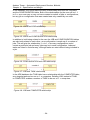
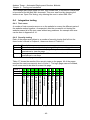
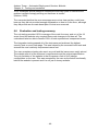
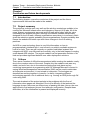
3.2.2 ADS vs. Novell ZENworkes 6 and Altiris SPS
In a product review by Harbaugh 2003, Microsoft ADS was judged not to be as
good overall as ZENworkes 6 or SPS, due to a very low score for ‘Interoperability’,
see Figure 3.1. This was because of a lack of features ADS has compared to its
competitors, see Figure 3.2.
Figure 3.1: Deployment system scores (Harbaugh, 2003)
Figure 3.2: Deployment system features (Harbaugh, 2003)
The website will to some extent extend the features of ADS to include patch
deployment, application deployment, work station deployment and role-based
deployment. With these extra features ADS would be a serious contender with its
rivals on interoperability and still retain its free price tag.
- 12 -
Andrew Turner – Automated Deployment Services Website
Chapter 3 – Research and risk assessment
As the Infrastructure and Laboratory Support (ILS) team can only use Microsoft
products due to company policy, ADS and RIS are the only two options available
to them. This could also be the case at other companies if they have licensing
agreements with Microsoft or already own Windows Server 2003 and do not have
the budget available to pay for ZENworkes or Altiris SPS.
3.2.3 Speed of deployment
ADS provides a large speed advantage over the current RIS system. This will
allow customer computer setups to be deployed faster, this decreases response
times to requests and gives the technicians more time to complete other work. A
full discussion and justifications on deployment speed is given in Appendix 3.2.
3.2.4 Cost of deployment
Using an ADS server introduces a number of costs benefits over using a RIS
server. As ADS requires less man hours per computer to create a customer’s
configuration money can be saved on staffing costs. A full discussion on other cost
savings and a case study is shown in Appendix 3.3
3.2.5 Advantages of C#
C# was chosen as the language to create the website as the ILS team required a
website that used Microsoft technologies to work. The website will be an ASP.Net
page with C# code behind.
C# has a number of benefits; shown in Table 3.2.
Feature
A strong C# community
XML compatibility
Truly object orientated
Built in error handling
Complied code
Managed code
Benefit
Provides lots of tutorials, papers and code
example
Allows easy manipulation of XML files
Provides ease of use for the all program objects
Helps capture user and data errors
Provides faster runtime execution
Helps to reduce unsafe code and exploits such
as buffer overflows
Ensures no memory leaks
Memory management and
garbage collection
Associated class library
Reduces the need to ‘reinvent the wheel’
Table 3.2: Benefits of C# (Meyne & Davis, 2002 and Williams, 2002)
- 13 -
Andrew Turner – Automated Deployment Services Website
Chapter 3 – Research and risk assessment
3.2.6 Advantages of Visual Studio
ASP.Net/C# can be programmed in a number of Integrated Development
Environments (IDEs) or written using a simple text editor. Visual Studio .Net 2003
was chosen due to the benefits shown in Table 3.3
Feature
Documentation
Benefit
MSDN has a wealth of articles and
examples
WYSIWYG web page designer
Allows easy creation of user friendly
web pages
Pretty printer
Makes code easier to view
Table 3.3: Benefits of Visual Studio (Microsoft, 2005)
3.2.7 Other project tools
During the project a number of other tools will also be used to complete certain
tasks, these are briefly described in Table 3.4.
Tool
ADS MMC snap-in
Description
Used to control the ADS server and view outcomes of
the websites task submissions
ADS Sequence
Used to create XML task files that instruct ADS on
Editor
actions or steps to take
SQL Server
Used to hold the ADS and website database
Rational Rose
Used to create database diagrams
Office tools
Used to create the report
Table 3.4: Other project tools
3.3
Risk assessment summery
The risk assessment identified a number of potential problems the system could
have encountered. All of the risks identified were assessed and solutions or
contingencies produced. A network designs for the final system as also produced
to reduce potential security problems even further. The full risk assessment can be
seen in Appendix 3.4.
- 14 -
Andrew Turner – Automated Deployment Services Website
Chapter 4 – Specification and design
Chapter 4
Specification and design
4.1
Introduction
This chapter covers the final specification and the design of the website. It also
covers the justifications and tradeoffs for specification and design decisions.
4.2
Specification
A specification helps to remove ambiguity about what the system will do and helps
define the users ‘true’ requirements. The specification focuses on what the system
will do, rather than how it will do it which is cover later in the design section.
(Dawson, 2004)
4.2.1 Functional specification
Table 4.1 shows the functional specification of the website and the justification for
each of the websites functions.
The website will
Allow the management of user
accounts
Allow the management of ADS tasks
Allow the management of computers
Display new configurations entered in
to the website separately
Show a summary of running ADS tasks
and ADS task errors
Not allow ‘bad’ data to be saved to the
database
Not to allow unauthorized viewing of
pages
Require users to login to the website
Have different security privileges
Allow the running of ADS tasks
Allow the queuing of multiple ADS
tasks
Allow the design of full, multi computer
setups
Continued over page…
Justification
To help with the maintenance of the
website and allow user accounts to be
added, edited and removed. Also, to aid
with the website security.
To allow user accounts to easily add,
edit and remove ADS tasks from the
website
To allow users to include or exclude
certain computers on the website. I.e.
production computers may not want to
be accessible from the website
To allow technicians to easily see when
a customer has made a request
To provide users with some feedback
about the state of their ADS tasks
If bad data cannot be saved to the
database the website will have greater
stability and will encounter less errors
To provide extra security
A user requirement for both security and
for statistics
A user requirement for security
A user requirement
A user requirement
A user requirement
- 15 -
Andrew Turner – Automated Deployment Services Website
Chapter 4 – Specification and design
Allow the running of multiple,
sequential ADS tasks
Allow the saving and loading of
previously run sets of ADS tasks
Show the statistics of computer, user
and ADS task use
Allow customers to enter configuration
change requests into the system
Table 4.1: Functional specification
A user requirement
A user requirement
A user requirement
A secondary user requirement
From the specification in Table 4.1, it can be seen that all of the users’ primary
requirements as discovered in Chapter 2 are being included in the website. Only
one of the users’ secondary requirements is included. This was to ensure the
users’ primary requirements were fully implemented and tested. Including all of the
secondary requirements would have required a long time to implement; this would
have impacted on the quality of the implementation of the user’s primary
requirements.
In addition to the specific user’s requirements, functionality such as adding and
removing user accounts has also been included. Although this was not specifically
asked for by the users, it is required to fulfil the users’ requirements.
4.2.2 Non-functional specification
Table 4.2 shows the non-functional specification of the website. This covers
qualitative aspects of the website. These are not fixed features or capabilities, they
are more of a general level of quality that the website tries meet.
The website will
Have 100% of errors with friendly error
messages
Have error messages that are
understood by most computer users
Be robust to unexpected data
Be user friendly
Be functional
Not submit errors to the ADS system
Follow HCI principles
Be maintainable
Justification
Gives the user more confidence that
the website functions correctly
Helps users to solve their own
problems without having to ask for help
To stop unexpected errors occurring on
the website
Ensures users will be happy using the
website
Computing professionals prefer
‘surface’ functionality rather than
‘hidden’ functionality
Ensures that computers will not be
accidentally reformatted or altered in
any adverse way
Helps with the usability of the website
Ensures the website will not become
out-of-date and unusable
Table 4.2: Non-functional specification
- 16 -
Andrew Turner – Automated Deployment Services Website
Chapter 4 – Specification and design
4.3
Website design
To ensure the website is as easy to use as possible for the users, it was designed
using Human Computer Interaction (HCI) principles and with usability in mind.
“If the interface is poorly designed, it can severely restrict the user’s ability to use
the system”
(Ravden and Johnson, 1989)
4.3.1 HCI principles
The main areas of HCI that were looked at in the design of the website were
Semiotics and Defensive design. These areas were chosen as they were identified
as important aspect of design for the website. If there were more time available
other aspects of HCI could also have been looked at in more detail.
Semiotics is a very good way of improving design of a user interface (UI) as it
associates things the user is already familiar with, to aspects of the UI.
“Semiotics is concerned with everything that can be taken as a sign”
(Eco, 1976) cited from (Chandler, 2004)
For example, the messages in Table 4.3 do not only tell the user information with
written text, they also give the user information by their colour and the picture next
to them.
Messages
Error: You did not type an input
Please type you username
The data was saved to the database
Table 4.3: Semiotics in use
These types of signs were used on the website to help improve feedback to the
user.
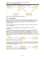
Defensive design is designing the UI to help reduce user errors, correct user
errors and recover from user errors (Garret, 2002). Figure 4.1 shows how
defensive design reduces the number of user errors.
- 17 -
Andrew Turner – Automated Deployment Services Website
Chapter 4 – Specification and design
Figure 4.1: Defensive design (Garret, 2002)
Table 4.4 shows how the website UI addresses each level of defensive design.
Level
Resolution
Prevention • Each data field has its name clearly indicated
• Data field names are self describing
• Each data field is a fixed selection choice where possible
• Data fields dynamically update other options on selection
• Page submission buttons grouped
Correction • Dynamically checks data inputs before page submission
• All data types are checked before the page submission is
successfully accepted
• All errors display a relevant error message
Recovery • All page code is placed in try and catch code blocks
• Page data is remembered and redisplayed
Table 4.4: Websites defensive design methods
Defensive design was not only used in the design of the websites UI, it was also
used to secure access to the websites pages. Table 4.5 shows how each level of
defensive design relates to each level of protection on the web pages.
In addition to the specific HCI elements used in the websites UI design, general
HCI principles from Nielsen were followed. These ensured the site did not have
any major design problems.
Level
Prevention
Correction
Protection
The user is redirected to the login page if they are not logged in
The user is redirected from the page if they are logged in but do
not have permission to view the page they entered in as the URL
Recovery
The pages controls are disabled and an error message displayed
if the user does not have permission to use them
Table 4.5: Web pages security methods
- 18 -
Andrew Turner – Automated Deployment Services Website
Chapter 4 – Specification and design
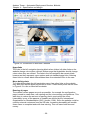
4.3.2 Design choice and justification
Throughout the design of the pages Microsoft’s website was used as a reference.
This made the ADS website look and feel more like an official Microsoft website.
This is not only a benefit to the ILS team, as the site will look more professional, it
should benefit anyone using the site as the design should be familiar to them,
reducing the need for user learning. A screenshot of the ‘view active
configurations’ page can been seen in Appendix 4.9 with the following design
features highlighted.
Site layout
The layout of the website follows a design covered on Microsoft’s bCentral. This
design is not only a design used by Microsoft’s website; it is a standard design
used on lots of popular websites and follows many of Nielsen’s Laws of Web User
Experience.
This was chosen as any user should be familiar with the website design of a
navigation bar on the left hand side and the main content to the right of it.
“Consistency is one of the most powerful usability principles: when things always
behave the same, users don't have to worry about what will happen. Instead, they
know what will happen based on earlier experience. Every time you release an
apple over Sir Isaac Newton, it will drop on his head. That's good.”
(Nielsen, 2004)
Colours
The main colours that are used on the website are shown in Table 4.6.
Colour
HEX
Where it is used
#f1f1f1
Left sidebar
#086dce Panel headings and page title
#cccccc
Table headers
#e9e9e9 Alternative table items
#ffffff
Standard background
#000000 Text colour
#ff0000
Error messages
Table 4.6: Colours used on the website
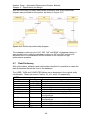
The colours in Table 4.6 were chosen as they are standard colours used by
Microsoft. All of the colours were taken from the Microsoft website, which can be
seen in Figure 4.2 and an additional page in Appendix 4.8.
- 19 -
Andrew Turner – Automated Deployment Services Website
Chapter 4 – Specification and design
Figure 4.2: Screenshot of Microsoft’s website
Hyperlinks
The links in the left navigation bar stay black when clicked, all other links on the
website change colour when clicked. Nielsen says that hyperlinks should change
colour when they are clicked. The links in the left navigation bar remain black
however as they represent menu options and not standard page links. Allowing
these links to remain black differentiates them from standard links to the user.
Menu bullet points
To further differentiate the left navigation menu from other links on the website
they also have square bullet points next to them. These bullet points can be seen
in Figure 4.2 in use on Microsoft’s website.
Reusing of pages
The website reuses pages as much as possible, for example the configuration
page is used to create new, edit existing and the view existing configurations. This
was done to reduce the amount of learning that is required by the users.
Learnability is one of the aspects of Usability as defined by the International
Organization for Standardization (ISO) (Jordan, 1998). Since the website could be
used by external customers from the ILS labs, increasing learnability will enable
those users to complete tasks with less training. This can save both time and
money.
- 20 -
Andrew Turner – Automated Deployment Services Website
Chapter 4 – Specification and design
4.4
Data modelling
4.4.1 Current database
ADS has a database that contains information about the computers in the data
centre, consequently this information does not need to be stored in the website’s
database. To ensure the integrity of the ADS database, if there were an error with
the website, a separate database has been created to hold any additional
information the website needs. To further protect the data in the ADS database,
the website only reads data from the ADS database, and uses WMI to write to the
database. Although these steps add complexity, the extra safety they provide to
the data out weighed the extra work required to implement them.
4.4.2 Identify entities and attributes
From studying ADS, it is easy to identify 3 main entities that work together to
complete the process of installing software on a computer, shown in Table 4.7.
Entity
The user
The task
Description
Physically starts the process
The logic used to make the computer complete the task chosen
by the user
The computer The physical object the will be effected by the running of the task
Table 4.7: Identified database entities
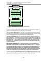
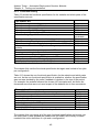
As the website will provide more power and greater flexibility with ‘the task’ part of
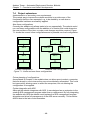
the process than ADS currently has, it will be extended as shown in Table 4.8.
Figure 4.3 shows this extension in diagram form.
Entity
Description
The job
A list of tasks to be run on a list of computers
The configuration A list of job to be run
Table 4.8: Extended entities from current ADS
- 21 -
Andrew Turner – Automated Deployment Services Website
Chapter 4 – Specification and design
Configuration
Job
ADS task
ADS task
ADS task
Job
ADS task
ADS task
Figure 4.3: New task hierarchy using extended entities
For each of the five entities that have been identified in the process, a number of
attributes that describe each of the entities can be produced.
The user entity (Appendix 4.1) – consists of user logon information and security
privileges. There are a number of security privileges that the user can have, this is
to give the maximum amount of granularity to the website security.
The task entity (Appendix 4.2) – provides a description of what a task does, the
path to the XML file that instructs ADS on the actions it should take, information on
which OSs the task will run on and counters to show how many times that task has
been used. A Bit is used to identify if a task installs an OS, and what OS it is, as
the user will only be allowed to choose one OS per job, due to multi-booting OSs
not being supported.
The job entity (Appendix 4.3) – contains information on the job’s creation, an
ordered list of tasks included in the job and a Bit to indicate if the job is still active.
The username and date of creation of the job are stored to enable statistics to be
produced about the activity of each user. In addition to this, future developments
were taken into consideration and the possibility of users reusing other users’ jobs
in their own configuration, so it would be useful to know who created each job.
If a job is active, the computers used as part of that job are no longer listed on the
new configuration page (as indicated by the IsActive Bit). This prevents users from
accidentally reformatting computers that are still in use by other users.
- 22 -
Andrew Turner – Automated Deployment Services Website
Chapter 4 – Specification and design
This introduces a problem with users wishing to plan out a configuration in
advance, as they will not be able to select computers that are in use now, but will
not be in use when they actually want to apply the configuration. This is a difficult
problem to overcome, as computers are not in use for a fixed period of time the
website is unable to predict when a certain computer will no longer be needed by a
user. As the data stored on the computers is valuable, the safest option was
chosen of not letting users choose a computer unless it is not currently in use. This
is to help prevent the accidental reformatting of computers.
The job entity will also have a description. This is not currently being used by the
website but is included for future developments.
The configuration entity (Appendix 4.4) – contains information on the
configuration’s creation, a description, an ordered list of jobs in the configuration
and an indicator of whether the configuration has ever been applied.
The indicator of whether the configuration has been applied or not will enable the
website to list configurations that may be requests from a customer separately. As
the username of the creator of the configuration is stored, a technician will be able
to view all of the unapplied configurations and see which ones have been
submitted by customers. This process could be further refined by indicating which
user accounts are customers and only displaying those configurations. This was
chosen not to be implemented as customers were identified as being the tertiary
users of the website, in Chapter 2, so other features of the website took
precedence.
The configuration does not require an indicator of whether it is active or not, as the
jobs inside the configuration are active or inactivate the configuration inherits their
status.
The computer entity (Appendix 4.5) – contains a foreign key to a the computer
on the website with a computer in the ADS database, a foreign key to show what
task the computer currently belongs to and counters to show how many times the
computer has been used.
4.5
Entity relationship identification
As discussed in the previous section, there are five entities that will interact during
the use of the website. In natural language, the user creates a configuration that
contains jobs, the jobs contain tasks and the tasks will be run on a computer.
Table 4.9 describes the terminology that will be used to describe the relationships
between the different entities.
Term
Description
0..1
Zero to one relationship
1..1
One to one relationship
0..n
Zero to many relationship
1..n
One to many relationship
Table 4.9: Description of relationship terms
- 23 -
Andrew Turner – Automated Deployment Services Website
Chapter 4 – Specification and design
In the database, the USER table will have a relationship with both the JOB table
and the CONFIGURATION table. Both of the relationships for the user will be 1..1
to 0..n, as a user may or may not have created a number of jobs or configurations,
but any job or configuration that was created was only created by one user.
Figure 4.4: USER and JOB relationship
Figure 4.5: USER and CONFIGURATION relationship
In addition to both being related to the user the JOB and CONFIGURATION tables
are also both related to each other, as a configuration is made up of a number of
jobs. This will give the relationship 1..n to 1..n as many configurations could
contain a particular job and many jobs may be in each configuration. Jobs and
tasks are linked in a similar way, although tasks can exist without being included in
a job.
Figure 4.6: CONFIGURATION and JOB relationship
Figure 4.7: JOB and TASK relationship
In the ADS database the TASK table has a relationship with the COMPUTER table,
as a singular task can be run on 1..n computers. Relating JOB, instead of TASK,
to COMPUTER enables a number of TASK to be run on 1..n computers.
Figure 4.8: JOB and COMPUTER relationship
- 24 -
Andrew Turner – Automated Deployment Services Website
Chapter 4 – Specification and design
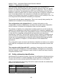
The full entity relationship diagram is shown below in Figure 4.9.
Figure 4.9: Complete entity relationship diagram
4.6
Normalization
As show in Figure 4.9, there are two many-to-many relationships present in the
database design, these are JOB to CONFIGURATION and JOB to TASK. These
relationships mean the design does not conform to the first normal form of
database design.
“To be in first normal form a table cannot have more than one entry in any field”
(Dawson, 2001:88)
To resolve this, a relationship table can be placed between each of these
relationships.
To resolve the problem between JOB and TASK a new entity called JOBTASK
was created. The relationship between TASK and JOBTASK is 1..1 to 0..n, as a
TASK may or may not be used in a JOBTASK but for JOBTASK to exist it must
contain one task. The relationship between JOB and JOBTASK is 1..1 to 1..n, as a
JOB must contain at least one JOBTASK to exist and a JOBTASK can only belong
to one JOB.
Figure 4.10: JOBTASK discovered entity
The solution to the CONFIGURATION and TASK relationship is similar, although if
a JOB exists it must belong to a configuration so the relationship between JOB
and CONFIGURATIONJOB is 1..1 to 1..n.
Figure 4.11: CONFIGURATIONJOB discovered entity
- 25 -
Andrew Turner – Automated Deployment Services Website
Chapter 4 – Specification and design
With all of the many-to-many relationships resolved a final entity relationship
diagram was produced for the system, as shown in Figure 4.12.
Figure 4.12: Final entity relationship diagram
The database conforms to the 1NF, 2NF, 3NF and BCNF of database design. It
was decided not to make the database conform to 4NF and 5NF as these an
advanced form of normalization and the website is not required for high
performance operation.
4.7
Data Dictionary
With all the tables, attributes and relationships identified it is possible to create the
data dictionaries that will be used in the database.
The USER, TASK and COMPUTER tables are as described in the original entity
identification. These are show in Table 4.10, 4.11 and 4.12 respectively.
USER
Attribute name
UserID
Username
Password
CanView
CanEdit
CanApply
CanActivate
Data Type
Integer
Varchar(20)
Varchar (20)
Bit
Bit
Bit
Bit
CanDeactivate
Bit
CanSave
Bit
IsAdmin
Bit
Active
Bit
Table 4.10: Final USER table
Description
Unique auto-increment Primary Key
Unique username
Users password
Indicates if the user can view configurations
Indicates if the user can edit configurations
Indicates if the user can apply configurations
Indicates if the user can activate
configurations
Indicates if the user can deactivate
configurations
Indicates if the user can save configurations
Indicates if the user is an Administrator
Indicates if the user account is still active
- 26 -
Andrew Turner – Automated Deployment Services Website
Chapter 4 – Specification and design
TASK
Attribute name
TaskID
FullDescription
ShortDescription
XMLPath
WillRunOn2k
WillRunOnXP
WillRunOn03
WillRunOnLH
Data Type
Integer
Varchar(500)
Varchar(30)
Varchar(200)
Bit
Bit
Bit
Bit
IsXP
Is2k
Is03
IsLH
Bit
Bit
Bit
Bit
CurrentCounter
Integer
Counter
Integer
Table 4.11: Final TASK table
COMPUTER
Attribute name
ComputerID
JobID
Description
Unique auto-increment Primary Key
Long description of what the task does
Short description on what the task does
File path to the XML file the task represents
Indicates if the task will run on Windows 2000
Indicates if the task will run on Windows XP
Indicates if the task will run on Windows 2003
Indicates if the task will run on Windows
Longhorn
Indicates if the task installs Windows XP
Indicates if the task installs Windows 2000
Indicates if the task installs Windows 2003
Indicates if the task installs Windows
Longhorn
Number of times the task has been run since
the counter was last cleared
Total number of times that task has been run
Data Type
Integer
Integer
Description
Unique auto-increment Primary Key
Foreign Key indicating which job is using the
computer JOB:JobID
ADSComputerID Integer
Foreign Key linking the ADS database to the
website database DEVICES:ID
CurrentCounter
Integer
Number of times the computer has been used
since the counter was last cleared
Counter
Integer
Total number of times the computer has been
used
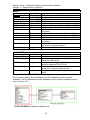
Table 4.12: Final COMPUTER table
The computer table is the link between the ADS database and the website
database. The link between the ADS database and the website database can be
seen in Figure 4.13.
Figure 4.13: ADS and website database link
- 27 -
Andrew Turner – Automated Deployment Services Website
Chapter 4 – Specification and design
Pictures of the full website database with data tables and the full ADS database
linked with the website data base can be seen in Appendix 4.6 and Appendix 4.7
respectively.
The JOB table no longer contains an ordered list of tasks as they are linked via the
JOBTASK table and the CONFIGURATION table no longer contains a list of jobs
as they are linked via the CONFIGURATIONJOB table. The JOB table can be
seen in Table 4.13 and the CONFIGURATION table in Table 4.14.
JOB
Attribute name
Data Type
JobID
Integer
CreatedBy
Integer
CreatedDate
DateTime
Active
Bit
Table 4.13: Final JOB table
Description
Unique auto-increment Primary Key
Foreign Key USER:UserID
The date and time the job was created
Indicates if the job is still active
CONFIGURATION
Attribute name
Data Type
ConfigID
Integer
Description
Varchar(30)
CreatedBy
Integer
CreatedDate
DateTime
IsNew
Bit
Description
Unique auto-increment Primary Key
Description of what the configuration does
Foreign Key USER:UserID
The date and time the job was created
Indicates if the configuration has ever been
applied
Table 4.14: Final CONFIGURATION table
The JOBTASK table and the CONFIGURATIONJOB table were both identified
during the normalization of the database. Each of these tables contains it own
attribute, Position, to identify in what order each entry should appear. The
JOBTASK and the CONFIGURATIONJOB tables can be seen in Tables 4.15 and
4.16 respectively.
JOBTASK
Attribute name
Data Type
JobID
Integer
TaskID
Integer
Position
Integer
Table 4.15: Final JOBTASK table
Description
Foreign Primary Key
Foreign Primary Key
Primary Key
CONFIGURATIONJOB
Attribute name
Data Type
Description
ConfigID
Integer
Foreign Primary Key
JobID
Integer
Foreign Primary Key
Position
Integer
Primary Key
Table 4.16: Final CONFIGURATIONJOB table
- 28 -
Andrew Turner – Automated Deployment Services Website
Chapter 5 - Implementation
Chapter 5
Implementation
5.1
Introduction
The following chapter covers the implementation of the website. It includes
explanations of problems overcome during the creation of the website and a
description of each section of the website.
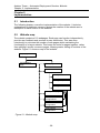
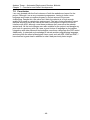
5.2
Website map
The website consists of 12 webpages. Each page can function independently,
provide user feedback and process its own submission. This was done
intentionally to minimise the number of web pages whilst maintaining the
functionality of a larger website. This keeps the code for pages together, rather
than splitting it across numerous pages, allowing easier editing of sections of the
website. Figure 5.1 shows a map of the website.
Login page
Left navigation
page
Home page
Site administration
Manage users
Manage computers
Manage tasks
Configuration page
View new
configurations
View active
configuration
View inactive
configuration
Figure 5.1: Website map
- 29 -
Andrew Turner – Automated Deployment Services Website
Chapter 5 - Implementation
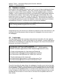
5.3
Database creation
All the tables were created with the word ‘web’ in front of them to distinguish them
from tables in the ADS database. They were created using the SQL enterprise
manger to create a SQL server database. Once the database tables, covered in
Chapter 4, were created and the primary keys selected the relationships between
the tables were created. These were created using the relationships tab in the
properties of each of the tables. Finally, the ASP.NET user account on the web
server was given permission to access the database. This allowed the website to
use integrated security to access the database, rather than requiring a username
and password. Extract 5.1 shows the code to access the database.
SqlConnection conn = new SqlConnection(@"Data Source=(local);
Initial Catalog=adsdb;Integrated Security=true");
Extract 5.1: Code to create a connection to the website database
Integrated security was chosen as it allows the password of the user account to be
changed without the password also having to be changed in the source code of
the webpages.
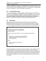
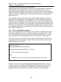
5.4
Login page
The login page checks the username and password entered by the user against
entries in the database. As with all the pages on the website, to ensure data being
submitted to the database are valid they are changed to the correct format before
being sent, as shown in Extract 5.2.
// Create SQL command to check password
SqlCommand cmd = new SqlCommand("SELECT * FROM webUser
WHERE Username=@Username AND Password=@Password",conn);
// Create cmd parameters for Username and Password
cmd.Parameters.Add("@Username",SqlDbType.VarChar);
cmd.Parameters.Add("@Password",SqlDbType.VarChar);
// Set the parameter to the users input
cmd.Parameters["@Username"].Value=txtUsername.Text;
cmd.Parameters["@Password"].Value=txtPassword.Text;
Extract 5.2: Data being formatted as a SQL data type
Correctly formatting the data allows the webpage to handle errors before the data
are sent to the database. This does not only ensure invalid data are not submitted
to the database, it also improves efficiency as the webpage does not have to wait
for a reply from the database before it can inform the user there is an error. There
is also an adverse effect that five lines of code are required instead of one. It was
decided that the inclusion of more lines of code was an acceptable trade off for
data validity.
- 30 -
Andrew Turner – Automated Deployment Services Website
Chapter 5 - Implementation
In addition to logging in the user, the login page also put the user’s information in a
session variable that it is available to other pages on the website, therefore it does
not have to be read from the database every time it is needed. The prototype page
is shown in Appendix 5.1 and the final page in Appendix 5.2.
5.5
Left Navigation page
The left navigation page provides hyperlinks to different pages on the website. It
uses the user information to decide which links are clickable by the user, i.e. if the
user is not an administrator the hyperlink for the administration menu is disabled.
The original design presented the user with buttons, these were changed to
hyperlinks for aesthetic and usability reasons. The prototype and final menu can
be seen on the left side of Appendix 5.4 and Appendix 5.5 respectively.
5.6
Home page
This page gives the user a brief summary of the activity of the Automated
Deployment Services (ADS) server if the user has the permissions to see the
information. As the login page puts the user’s information in a session variable,
any of the webpages can read this information back with the code in Extract 5.3.
private DataGrid GetUserInfo()
{
// Create the user information datagrid
DataGrid dtgUserInfo= new DataGrid();
string teststring;
// Try to get user information, if not present redirect to login page
try
{
dtgUserInfo = (DataGrid)Session["UserInfo"];
teststring=dtgUserInfo.Items[0].Cells[0].Text;
return dtgUserInfo;
}
catch
{
Response.Redirect("login.aspx");
return null;
}
}
Extract 5.3: Method to retrieve user information
Not only does Extract 5.3 retrieve the user’s information, it also redirects the user
to the login page if this information cannot be retrieved, i.e. the user has not
logged in. A session variable was chosen over a cookie to pass the information as
the information in a session variable will be lost once the user closes the browser
or after a timeout period, so the user does not have to worry about the security
risks of leaving information in a cookie on the computer they are using to access
the website.
- 31 -
Andrew Turner – Automated Deployment Services Website
Chapter 5 - Implementation
Once the page has the user’s information, it can decide if the user has the correct
permissions to view a summery of the ADS server’s activities, i.e. the view
permission. If the user does have view permissions the page calls three separate
methods to display the new configurations, running configurations and error
messages. Each of these methods is similar; the method to read and display the
running configurations is show in Appendix 5.3.
The home page differs slightly from the original prototype. It was decide that the
user would not be shown a full list of new configurations as this list became very
large, to avoid long scrolling pages they are informed there are new configurations
and given a link to view them. The user cannot click on the running configurations
or the errors to get more information as shown in the prototype due their being
limited documentation, so the time required to implement this would have
outweighed the benefits it provided. The prototype design is shown in Appendix
5.4 and the final design in Appendix 5.5.
5.7
Configuration page
The configuration page is by far the most complex page of the website. It allows
the creation, loading, saving, viewing, editing and application of configurations.
There are over 1,500 Lines Of Code (LOC) for manipulation of data between the
website, database and the ADS server.
5.7.1 Loading of a configuration
When a user wants to view, edit or apply an existing configuration, the ConfigID of
that configuration is passed to the configuration page via a session variable, in the
same way that the user’s information is passed. Table 5.1 shows the process the
page follows when it receives a ConfigID to load. The LoadComputer method is
shown in Appendix 5.6.
To reduce the number of times the website has to access the database, to
improve performance, the SQL commands join tables where possible to retrieve all
the data required in one trip. Extract 5.4 shows an example of a SQL statement
joining tables when the TaskIDs and their position numbers are read for a
configuration.
cmd = new SqlCommand("
SELECT webJobTask.TaskId, webJobTask.PositionNo
FROM webJobTask INNER JOIN webConfigJob
ON webJobTask.JobId=webConfigJob.JobID
WHERE webConfigJob.ConfigID=@ConfigID
ORDER BY webJobTask.PositionNo",conn);
Extract 5.4: SQL statement joining database tables
- 32 -
Andrew Turner – Automated Deployment Services Website
Chapter 5 - Implementation
No Method
1
LoadOSTasks()
44 LOC
Description
• Select all tasks that install OSs
• Loop through each OS task box and bind
the tasks to the box
• Loop through each OS task box and select
the OS that was selected when the
configuration was saved
2
LoadConfig()
• Get the configurations description
134 LOC
• Get all the jobs in the configuration
• Loop through each job and call
LoadOtherTasks(Job Position)
• Loop through each job and update the
other task boxes to select the task that was
selected when the configuration was saved
3
LoadOtherTasks(int) FOR EACH JOB
132 LOC
• Select all the tasks that will run on the
OS selected, or all tasks if no OS is
selected
• Loop through each task box and bind it
to the tasks
4
LoadComputers()
• Select all free computer and computers in
116 LOC
the configuration
• Loop through each of the computer list
boxes, bind the computers and select the
ones that are in use by the configuration
Table 5.1: Steps taken to load a configuration
5.7.2 Saving of a Configuration
When a user wants to save the configuration it is written to the database. As with
all the webpages the data is converted into the correct SQL data type before being
submitted to the database. To further ensure the data saved to the database is
correct, in addition to valid, the page runs a number of error checking methods.
Although the page takes longer to submit and increases its size, it is worthwhile to
ensure the information in the database is correct. Table 5.2 shows the process the
page takes to save the configuration to the database.
- 33 -
Andrew Turner – Automated Deployment Services Website
Chapter 5 - Implementation
No Method
1
btnSave_Click
28 LOC
2
3
4
5
Description
• Check there is a short description
• Call CheckIsIncludedWithNoTasks()
• Call ComputersOnlySelectedOnce()
• Call SaveConfigToDatabase()
CheckIsIncluded_
• Copy the Include Job check boxes
WithNoTasks()
• For each checked check box
106 LOC
• Copy the Jobs task boxes
• Check to see if at least one of them
has a task selected
• Return True if a Job is selected without
any tasks selected and False if all Jobs
checked have tasks selected
ComputersOnly_
• Copy the computer list boxes
SelectedOnce()
• Set OnlySelectedOnce=true
75 LOC
• For each list box
• For each list box after the current
list box
• Check each selected computer
in the current list box to the
selected computers in the list
boxes after
• If the same computer is selected
in both boxes display an error
and set
OnlySelectedOnce=false
• Return OnlySelctedOnce
SaveConfigToDatabase() • Insert the config information in to
270 LOC
webConfig
• Read back the new ConfigID
• Loop through each job that is selected
• Copy the tasks selected in the
current job
• If there are tasks selected Insert the
job into webJob
• Read back the new JobID
• Insert a link to the config into
webConfigJob
• If there is an OS task selected
Insert a link into webJobTask
• Loop though the other tasks and
Insert a link into webJobTask if they
are selected
• Set the JustSaved state variable to
true
On page reload as
• Load the configuration from the
JustSaved=True
database
Table 5.2: Steps taken to save a configuration
- 34 -
Andrew Turner – Automated Deployment Services Website
Chapter 5 - Implementation
As checking every computer recursively to see if it is selected twice could take a
lot of time the ComputerOnlySelectedOnce method uses four nested loops with
three additional nested if statements to only check computers that have been
selected for efficiency. The ComputerOnlySelectedOnce method can be seen in
Appendix 5.7.
5.7.3 Applying a configuration
Applying a configuration was the most challenging part of the project. This is
where the tasks selected by the user are converted to XML files ADS can
understand, and the configuration is submitted to ADS to be run.
As applying a configuration was such a complex process, it was split up into a
number of smaller tasks of reading all the correct information from the database,
creating XML files, joining XML files, creating ADS computer sets and running
ADS jobs. Once all of the sections worked separately they were bought together to
enable a configuration to be applied.
XML task files
The XML task files are sequences of steps that an ADS server will understand and
can follow. These file were created using the ADS sequences editor, a sample file
created to install .NET framework can be seen in Appendix 5.8. Each one of these
XML files completes a number of steps to complete a single task, so to enable
ADS to run a number of tasks sequentially these XML files must be merged.
XML wrapper file and XSLT document
To merge the XML tasks files together, a wrapper document is first created that
lists all the XML task files to be joined, a sample wrapper document can be seen in
Appendix 5.9.The wrapper file then has a XSLT document applied to it, this can be
seen in Appendix 5.10. The XSLT document takes the file paths from the wrapper
document and outputs another XML file that includes all the steps from all of the
source files. Figure 5.2 shows a graphical representation of this process.
File 1
File 2
File 3
Step 1a
Step 1b
Step 2a
Step 3a
Step 3b
Output
Wrapper file
Transform
File1.XML
File2.XML
File3.XML
XSLT document
Figure 5.2: Joining of XML tasks
- 35 -
Step 1a
Step 1b
Step 2a
Step 3a
Step 3b
Andrew Turner – Automated Deployment Services Website
Chapter 5 - Implementation
The full application process
In addition to merging XML files there are a number of other actions that take
place before a configuration is applied. Table 5.3 shows the steps taken by the
website when the Apply button is pressed.
No Method
1
CheckIsIncluded_
WithNoTasks
2
ComputersOnly_
SelectedOnce
3
ComputerIs_
Selected(int)
35 LOC
5
4
SaveConfigTo_
Database()
ApplyConfig(int, int)
336 LOC
Description
See Table 5.2
See Table 5.2
•
•
Set FoundOne=False
Loop through the computer list box
represented by the passed int
• If a computer is selected set
FoundOne=True
• If FoundOne=False update the error
message
• Return FoundOne
See Table 5.2
•
Read the jobs in the config from
webConfigJob
• For each job read in all of the tasks from
that job from webJobTask
• For each job
• Create a XML file to represent the job
• For each task in the job
• Update the usage statistics
• Read the XML path for the task
from webTask
• Write the XML path for the task to
the jobs XML file
• Close the jobs XML file
• Transform the jobs XML file using the
XSLT document to include the full
XML document
• For each job
• Create a new Set of computers in
ADS using WMI
• Add all of the computers in the current
job to the set
• Update the computer usage statistics
• For each job
• Run the outputted XML file on the
computer Set in ADS using WMI
• Update the config in webConfig so that it
is no longer marked as new
Table 5.3: Step taken to apply a configuration
- 36 -
Andrew Turner – Automated Deployment Services Website
Chapter 5 - Implementation
Figure 5.3 shows a flow diagram of the process of applying a configuration.
Read in the
jobs for the
configuration
Read all the
tasks for each
of the jobs
Create a XML
wrapper file for
the job
XML
wrapper file
Update the task
statistics, get the XML
path and write it to the
wrapper file
Website
database
Apply the XSLT
document to
the wrapper file
XSLT
document
XML task
files
Create ADS computer
sets, add computers
and update computer
statistics
Output XML
task file
Apply the
outputted XML
file to the set
ADS
computer
set
Update the
config to no
longer be new
Figure 5.3: Flow diagram for applying a configuration
Appendix 5.11 shows the code that creates the XML wrapper file and merges the
XML documents. Appendix 5.12 show the code that creates the ADS computer
sets, adds the computers and updates the computer statistics. Appendix 5.13
shows the code to apply the XML configurations to the ADS computer sets created.
- 37 -
Andrew Turner – Automated Deployment Services Website
Chapter 5 - Implementation
The ApplyConfig method takes two parameters,
ApplyConfig(int RunFromOnwards, int RunOnly). The first parameter makes the
method apply only jobs that have an equal or value higher than it, i.e. if the
parameter equals 3 only jobs three and four are applied. The second parameter
make the method only apply the job number of the parameter, i.e. if the parameter
equals 2 only job two will be applied. This allows the user to be selective about
which jobs to run.
The final page design was similar to the prototype design, these can be seen in
Appendix 5.15 and Appendix 5.14 respectively. The main difference is that the
final page cannot dynamically create tasks or jobs, it is fixed to five tasks per job
and four jobs per configuration. This was due to difficulties in getting dynamically
created controls to remember their values after a page submission. As there is no
efficient way of doing this, it was decided that fixing the number of jobs would be
an acceptable trade-off for the amount time that could then be saved and spent on
other areas of the website.
5.8
View configuration pages
When a user wants to either view new, active or inactive configurations they are
read from the database. There is a separate page to list configurations in each
state. The pages are separate as users have different permissions, e.g. a user
may be able to view new configurations but not view inactive configurations.
To ensure users can only perform actions they have permissions to perform the
pages check the user’s privileges. Extract 5.4 shows a cut down version of the
code that performs the check.
//find out if the user has permissions to deactivate tasks
//Get the userinfo
DataGrid dtgUserInfo=GetUserInfo();
if(dtgUserInfo.Items[0].Cells[7].Text =="True")
{
// Let the user perform the action
}
Else
{
// ERROR: The user does not have the permissions to do this task
}
Extract 5.5: Code to check the user’s privileges
Extract 5.5 uses the command if(dtgUserInfo.Items[0].Cells[7].Text =="True")
to check if the user can deactivate configurations. The index used in the Cells
array relates to the row number of an attribute in the webUsers table of the
database. Table 5.4 shows the row number of each of a user’s attributes.
- 38 -
Andrew Turner – Automated Deployment Services Website
Chapter 5 - Implementation
Row Number
Attribute Name
0
UserID
1
Username
2
Password
3
CanView
4
CanEdit
5
CanApply
6
CanActivate
7
CanDeactivate
8
CanSave
9
IsAdmin
10
Active
Table 5.4: User attribute row numbers
The final view configurations pages differed from the prototype designs slightly;
these can be seen in Appendix 5.17 and Appendix 5.16 respectively. The page no
longer has a ‘view’ link as the configuration is automatically set to read only if the
user does not have permission to edit it. Also, there is no longer a ‘Reapply’ link,
as it was decided it was safer to force the user to view the configuration before
they reapplied it, to make sure they did not reformat the wrong computers by
mistake.
5.9
Administration page
The administration page simply displays three hyperlinks to the manage tasks,
users and computer pages. A final screenshot of the administration page can be
seen in Appendix 5.18.
5.10 Manage users, tasks and computers pages
The manage users, tasks and computer pages allow administrators of the website
to manage and maintain it.
Manage users page
The manage users pages is similar to the user administration page on many
websites. This page can add and edit user accounts. However, the page cannot
delete user accounts as this would remove information about users who may have
created configurations. Instead, the page allows administrators to disable user
accounts.
Appendix 5.19 shows the manage users page allowing administrators to create
user accounts and Appendix 5.20 show the page allowing administrators to edit
user accounts. When the administrator switches between the create and edit
mode the username input switches from a text input box to a dropdown selection
box, allowing them to select the user they want to edit from a list, this is an aspect
of defensive design and usability.
- 39 -
Andrew Turner – Automated Deployment Services Website
Chapter 5 - Implementation
Manage tasks page
The manage tasks page allows administrators to create database entries that link
a task on the website to a XML file on the hard disk. The administrator can also
edit tasks in a similar way used on the manage users page. Appendix 5.21 shows
the manage tasks page allowing administrators to create tasks and Appendix 5.22
shows the page allowing them to edit tasks.
Manage computers page
The manage computers page allows an administrator to create a link between a
computer in the ADS database and the website. This is a simple task of selecting
the computers they want to be visible on the website and clicking ‘Add’. If they
want all computers to be listed on the website they can click ‘Add All’. To remove
links from the website to the ADS database they can click ‘Remove’ or ‘Remove
All’. The manage computers page is shown in Appendix 5.23.
5.11 Statistics page
The statistics page allows administrators to view the usage statistics for tasks,
computers and users. It reads the values from the database and displays them to
the user. The users can reset the statistic counters so they could for example see
what task have been used each week. The final design for the statistics page is
shown in Appendix 5.24.
5.12 Style sheet
To ensure consistency in the style of the website a Cascading Style Sheet (CSS)
was used. This was only very simple and set the website font and table style.
Further formatting could be added, if needed, that would automatically be applied
to every page on the website.
- 40 -
Andrew Turner – Automated Deployment Services Website
Chapter 6 – Testing and evaluation
Chapter 6
Testing and evaluation
6.1
Introduction
The following chapter covers the testing and evaluation of the website.
“Users have an infinite potential for making unexpected misinterpretations of
interface elements and for performing their job in a different way than you imagine”
(Nielsen, 1994).
The testing of the website was split into a number of categories to ensure each
part of the website was tested thoroughly as a single error could mean vital
business data would be lost.
6.2
Testing outline
6.2.1 Unit testing outline
Table 6.1 outlines the types of unit testing carried out on the website, these were
to ensure each control and function of the website worked correctly when used.
Testing type
Control validation testing
Description
Every control on the website was tested to ensure
it preformed the correct actions when it was used
Control verification testing
The code for each control was tested to ensure
that it preformed the correct action in the correct
way
Function validation testing
Every function on the website was tested to
ensure it produced the correct result
Function verification testing Each function on the website was tested to
ensure it could handle errors correctly and was
producing the correct output in the correct way
Table 6.1: Types of unit testing performed on the website
6.2.2 Integration testing outline
Table 6.2 outlines the types of tests that were used to assess how well the web
pages integrated with each other.
Testing type
Test cases
Description
Common scenarios were run through to ensure the different
parts of the website worked together
Security testing Each page was tested to ensure it was secure from
unauthorised access and use
Table 6.2: Types of integration testing performed on the website
- 41 -
Andrew Turner – Automated Deployment Services Website
Chapter 6 – Testing and evaluation
6.2.3 Acceptance testing outline
Table 6.3 outlines the types of tests used to evaluate how well the website met the
user’s needs.
Testing type
Usability testing
Description
The site was tested by users to see if the site was easy
to use
System testing
The site was tested against the users requirements to
see if they were met
Functional testing
The site was tested against the system specification to
see if it was fulfilled
Table 6.3: Types of acceptance testing performed on the website
6.3
Unit testing
Table 6.4 shows the web pages that passed all of the unit tests. These pages are
able to handle unexpected errors and prevent bad data from being entered into the
database. Error and status messages that are displayed by the pages are listed in
Appendix 6.1 and Appendix 6.2 respectively.
Page name
Test results
Login page
Appendix 6.3
Home page
Appendix 6.4
View unapplied configurations page
Appendix 6.5
View active configurations page
Appendix 6.7
View inactive configurations page
Appendix 6.8
Statistics page
Appendix 6.9
Manage users page
Appendix 6.10
Manage computers page
Appendix 6.11
Left menu page
Appendix 6.13
Table 6.4: Web pages that passed all unit tests
Table 6.5 shows the web pages that failed at least one of the unit tests. These
pages had at least one component that either did not function correctly or allowed
errors to be entered into the database.
Page name
Test results
New configurations page
Appendix 6.6
Manage tasks page
Appendix 6.12
Table 6.5: Web pages that did not pass all unit tests
Although the new configurations page failed 18 tests, all of the failures were due to
two over stringent error checking functions. For example, if the user wanted to
apply Job 4 only, and there was an error in Job 1, the page would not let Job 4 be
applied. This problem was due to the affected functions checking the configuration
as a whole, instead of each job individually. This was fixed by changing the
following two functions to accept a job number:
ComputersOnlySelectedOnce() > ComputersOnlySelectedOnce(int JobNumber)
CheckIsIncludedWithNoTasks() > CheckIsIncludedWithNoTasks(int JobNumber)
- 42 -
Andrew Turner – Automated Deployment Services Website
Chapter 6 – Testing and evaluation
The manage tasks page failed one test, test number 299, it allowed an invalid path
to be entered for the task XML document. This error was fixed by changing the
textbox to an ‘Open File’ dialog, only allowing the user to select XML files.
6.4
Integration testing
6.4.1 Test cases
A number of test scenarios were run on the website to ensure the different parts of
the website worked together. As expected, after the successful unit testing the
website passed all of the test cases without any problems. An example test case
can be seen in Appendix 6.14.
6.4.2 Security testing
Each of the pages was subject to a number of security checks that fell into the
three levels covered in Chapter 4; these are shown in Table 6.6.
Level
1
2
Description
The user is redirected to the login page if they have not logged in
The user is redirected from the page if they do not have the
permissions to view the page
3
The page controls are disabled if the user does not have the
permissions to use them
Table 6.6: Levels of page security
Table 6.7 shows the results of the security tests on the pages. All of the pages
reached the maximum security level of Level 1. The login page was not included,
as all users need to be able to access this page.
Level 1
Level 2
Level 3
Left menu page
Manage tasks page
- 43 -
Manage computers page
Manage users page
Statistics page
New configurations page
View inactive configurations page
View active configurations page
View unapplied configurations page
Home page
Table 6.7: Security levels of the web pages
Andrew Turner – Automated Deployment Services Website
Chapter 6 – Testing and evaluation
6.5
Acceptance testing
6.5.1 Usability testing
There was only one major usability issue with the website which was the
terminology used, this confused users about how to run tasks on computers.
The users became confused as ‘jobs’ and ‘configurations’ are not part of a normal
ADS system, and they tested the website without being told what jobs or
configurations were. ADS only allows users to run tasks, so a user must learn that
on the website a job is a number of tasks and a configuration is a number of jobs.
This problem can be avoided in future by users being shown the User Manual
before they use the website.
All of the other usability issues on the website were minor, a full list can be found
in Appendix 6.14.
6.5.2 System testing
Table 6.8 shows the users’ original requirements and which requirements the
website met.
Requirement
Ability to run ADS tasks remotely
Ability to queue ADS tasks
Ability to design full, multiple computer setups
Ability to reapply saved computer setups
Ability to produce statistics on computer and software
usage
The system must have some form of security
Table 6.8: How well the user requirements were met
Fully met
Fully met
Met with constraints
Fully met
Fully met
Fully met
All of the user requirements were met although the user is currently limited to four
jobs in a single configuration. This is because there was no efficient way to
dynamically create tasks and jobs. This can be changed in the code to allow more
than four jobs per configuration, or could be solved by splitting large setups into a
number of smaller configurations.
- 44 -
Andrew Turner – Automated Deployment Services Website
Chapter 6 – Testing and evaluation
6.5.3 Functional testing
Table 6.9 shows the functional specification for the website and which parts of the
specification are met.
The website will
Allow the management of user accounts
Allow the management of ADS tasks
Allow the management of computers
Allow the running of ADS tasks
Allow the queuing of multiple ADS tasks
Allow the designing of full, multi computer setups
Display new configurations entered in to the website separately
Allow the running of multiple, sequential ADS tasks
Allow the saving and loading of previously run sets of ADS tasks
Allow customers to enter configuration change requests into the
website
Show the statistics of computer, user and ADS task use
Require users to login to the website
Have different security privileges
Show a summery of running ADS tasks and ADS task errors
Not to allow unauthorized viewing of pages
Not allow bad inputs to be saved to the database
Table 6.9: How well the functional specification was met
Fully met
Fully met
Fully met
Fully met
Fully met
Met with
constraints
Fully met
Fully met
Fully met
Fully met
Fully met
Fully met
Fully met
Fully met
Fully met
Fully met
The website fully met the functional specification but again was limited to four jobs
per configuration.
Table 6.10 shows the non-functional specification for the website and which parts
are met. As the non-functional specification is qualitative, whether the specification
was met was decided by the users’ feedback in relation to the size of the project.
For example, the website followed the chosen HCI principles well, but there are
thousands more that were not used as part of the website due to time constraints.
The website will
Have 100% of errors with friendly error messages
Have error messages that are understood by most computer users
Be robust to unexpected data
Be user friendly
Be functional
Not submit errors to the ADS system
Follow HCI principles
Be maintainable
Table 6.10: How well the non-functional specification was met
Fully met
Mostly met
Fully met
Mostly met
Fully met
Fully met
Fully met
Fully met
The website fully met nearly all of the non-functional specification and mostly met
the other parts. It was decided the website was not totally user friendly as users
needed to be told a definition of a job and a configuration.
- 45 -
Andrew Turner – Automated Deployment Services Website
Chapter 6 – Testing and evaluation
“Error messages should always be constructive and help users to overcome the
problem instead of simply pointing out that there is trouble”
(Nielsen, 2000).
The users decided that the error messages were not as clear as they could have
been as they did not provided enough explanation on how to fix the error, although
they did provide an accurate description of what error occurred.
6.6
Evaluation and testing summery
The unit testing provided 100% coverage of the code for errors, and out of the 19
errors found the website only required three code changes to fix them all. The
code should also be able to handle 100% of both expected and unexpected errors.
The integration testing passed all of the test cases and achieved the highest
security level on every web page. This was helped by the successful unit tests and
ensured the user’s security requirements were met.
The user acceptance testing also went very well and the issues were easily solved.
The website met all of the customer’s requirements and the original specification.
The only limitation of the website is that it imposes a limit of four jobs per
configuration on the user. This was accepted by the user as the actual functionally
behind the website is present and it is not just a dummy website.
- 46 -
Andrew Turner – Automated Deployment Services Website
Chapter 7 – Conclusion and further developments
Chapter 7
Conclusion and future developments
7.1
Introduction
The following chapter covers the conclusion of the project and the future
improvements that could be made to the website.
7.2
Project summary
The project as a whole went very well and the solution created was suitable to be
used by the Microsoft Infrastructure and Laboratory Support (ILS) labs. All of the
users’ primary requirements were met and ILS team were happy with the extra
functionality the website provided. Although the website created was primarily
designed for the ILS team, different organisations were taken in to account, which
gives the website a greater portability across organisations. Greater portability also
means the website will better cope with future changes in the ILS working
practices.
As ADS is a new technology there is very little information on how to
programmatically interface with it, and currently no publicly available systems to
look at for help. There are still currently no generic web based systems that
integrate with ADS, even Microsoft are currently only in the beta stages of creating
a web based ADS solution. The project website is a first generation solution of its
kind and provides significant benefits over older deployment solutions.
7.3
Critique
There were a number of difficulties encountered whilst creating the website, mostly
due to the complex nature of the work. Despite this, the website code was very
stable, and error free, due to the extensive testing that took place and my
continuing improvement at programming with C#. Although Microsoft is correct in
saying Windows Management Instrumentation (WMI) can be used to administer
an enterprise environment, it is not simple to implement. Technologies are
described as working together in harmony. In reality, integrating different
technologies requires a lot of additional work, e.g. running an ADS job through C#
code using WMI.
The main drawback of the project website is the problems with the flow of
information when pages are submitted. Due to the difficulty of the task and the
language chosen, there was no efficient way of passing the data. Hence, the user
was limited to five tasks per job and four tasks per configuration. Despite these
difficulties, all of the information is passed and displayed correctly.
- 47 -
Andrew Turner – Automated Deployment Services Website
Chapter 7 – Conclusion and further developments
7.4
Project extensions
Implementation of secondary user requirements
The easiest way to improve the website would be to provide more of the
functionality that the user requested, e.g. to be alerted by e-mail when a
configuration had been successfully applied.
Non-linear configurations
Currently the website only allows tasks to be run sequentially. The website could
run non-linear configurations with the addition of a function that could determine
the new positions of the jobs, no major code changes would be required. Figure
7.1 shows the current linear configurations and a potential non-liner configuration.
Job 1
Job 2
Job 1
Job 2a
Job 2b
Job 3
Job 3
Job 4
Job 4
Current Configuration
Potential new Configuration
Figure 7.1: Linear and non-linear configurations
Future planning of configurations
As explained in Chapter 4, the website does not allow users to select a computer
that are already in use to ensure they are not accidentally reformatted. This could
be improved by allowing users to select the computers, but not allowing the
configuration to be applied.
Further integration with ADS
Although the website integrates with ADS, it was designed as an extension to the
existing ADS management program rather than a replacement. By fully integrating
the website with ADS the website could replace the ADS management program
altogether and allow full management of the ADS server remotely. This would be
difficult due to the lack of documentation.
- 48 -
Andrew Turner – Automated Deployment Services Website
Chapter 7 – Conclusion and further developments
7.5 Conclusion
I am very pleased with the final outcome of both the website and report for the
project. Although I am a very competent programmer, having to learn a new
language and create a complex program in a short amount of time was
challenging. Despite this, the users and I think the website is of high enough
quality to be used in a production environment. The lack of documentation meant
that trial and error had to be used at the start of the project to figure out how to
interface with ADS, although once these problems were overcome the website
worked well. All the tools chosen were also suitable for the project, and despite my
prior lack of experience with C# it was a good choice of language as it simplifies
integration with other Microsoft technologies more than a language like PHP would.
Additionally, it extended my knowledge to include another programming language,
and along with the other technologies I have used, such as ADS, WMI and XML, I
have learned a great deal in addition to what I had previously been taught.
- 49 -