1
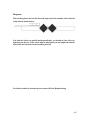
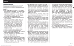
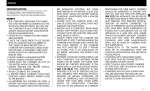
DeWan
AIR-FLOW HOT AIR
CONTINUOUS
HEAT SEALER
TM.
SERIAL #________________________
DATE___________________________
THIS MACHINE AND ALL MATERIAL IN THIS
MANUAL MAY BE COVERED UNDER MORE
THAN ONE U.S. PATENT.
ALL RIGHTS RESERVED
BEFORE OPERATING THIS MACHINE, PLEASE READ OWNERS MANUAL
CAREFULLY. THIS OWNERS MANUAL HAS BEEN DESIGNED TO
INSTRUCT YOU AS TO THE PROPER MANNER IN WHICH TO OPERATE
AND MAINTAIN THIS EQUIMENT, AND MOST IMPORTANTLY HOW TO
OPERATE THIS MACHINE IN A SAFE AND EFFICIENT MANNER.
PLEASE KEEP THIS MANUAL FOR FUTURE REFERENCE.
DEWAN PACKAGING INC.
P.O. BOX 191
1809 NEVA ROAD
ANTIGO, WI 54409
1-888-803-4515
www.dewanpackaging.com
1
TABLE OF CONTENTS
PAGE 3- INTRODUCTION,
SAFETY FEATURES,
REQUIRMENTS,
RECOMMENDATIONS.
PAGE 4- ADJUSTABLE FEATURES
PAGE 5- OPERATIONS
PAGE 6- OPERATIONS CONTINUED
PAGE 7- TROUBLE SHOOTING
PAGE 8- TROUBLE SHOOTING
CONTINUED
PAGE 9- TECHNICAL ASSISTANCE
PAGE 10-TECHNICAL ASSISTANCE
CONTINUED
PAGE 11- TECHNICAL ASSISTANCE
CONTINUED
PAGE 12- DIAGRAM
PAGE 13- PARTS LIST
PAGE 14- WIRING SCHEMATIC
2
Introduction:
The intended purpose of the DeWan Hot-Air Continuous Heat Sealer is to apply a
quality seal on polyethylene open mouth bags ranging in thickness from one to six
mils. This machine is designed to operate from 1 to 62 feet per minute depending on
the thickness of the bag being sealed. The features integrated into this machine are
completely self contained which means all you need to do is plug it in and feed the
bags.
Safety Features:
This machine has been implemented with two important safety features.
The first one is the front deck. It has been designed to allow it to swing away from
the rear deck in the event that any foreign objects are inadvertently pulled in by the
belts. If a hand or clothing gets caught in the belts, just pull toward the front and
the belts will separate allowing quick and easy removal.
The second safety feature this machine boasts is a solid state timer wired into the
circuits. What’s important about this is that while the machine is operating the heat
elements can run up to 600 degrees. When the main power is turned off (DO NOT
UNPLUG) the timer function turns on for five minutes and continues to supply
power to the blower to cool the heat elements and to the in-feed motors to keep the
belts moving to avoid the possibility of scorching them or causing a fire.
Requirements:
This machine requires one 110volt 30amp outlet.
If a conveyor was provided with this machine it may be plugged into the auxiliary
outlet located on the rear of the machine.
Recommendation:
DeWan Manufacturing recommends using a high polyethylene content bag for best
results.
It is recommended to leave this machine plugged for at least five minutes after
turning the main switch off to allow for the cool down cycle.
3
Adjustable Features:
There are six features that will need to be in proper adjustment to obtain a quality
seal, they include:
Crimp Wheels- These two steel knurled wheels are located underneath the decks
just to the left of the heat manifolds. This machine will not produce a good seal if
these wheels are not properly aligned. See trouble shooting section for details.
Temperature Controller- Located on the upper left corner of the top panel. Use this
adjustment in conjunction with the in-feed belt speed to obtain a quality seal.
In-feed Belt Speed Control- This is the only knob located on the lower panel. It
regulates the speed at which the bag passes through the heaters and crimp wheels.
Airflow Control- You’ll find this dial just to the right of the temp control on the
upper panel. It controls the speed of the blower motor, which in turn determines the
amount and speed of the air passing over the heat elements.
Note: To much air passing over the heat elements will have a cooling effect and will
not provide a proper seal. It is recommended to keep this adjustment between or
close to 3 – 6.
Heater Manifolds- Located underneath both decks, these manifolds contain the heat
elements. Both manifolds are adjustable to a point, and should maintain an even gap
over center of the belts of not less than ¼” and no more than ½”. The manifolds
should also maintain an even height in respect to the series of holes so they are
heating the same area of the bag on both sides. The manifolds should be set so that
they are as close together as can be without contacting the bag on either side as it
passes.
Height Adjustment Screw- Adjust the height of the deck from your conveyor by
loosening the locking bolts against the vertical tube and turning the handle until you
achieve the desired height. Remember to tighten the locking bolts.
4
Operations:
To begin with, set the temperature controller to zero, the blower motor to five and
turn the in-feed belt control about ¼ of a turn. Now plug the cord into a 110volt
30amp outlet. At this point the machine should remain off. Power the machine on by
flipping the rocker switch located on the upper cover. You should hear the blower
motor kick on and the in-feed belts should be moving.
Now, depending on the thickness of the bag you will adjust the temperature
controller. For thinner bags such as the thickness of an ice bag you can start around
175 degrees. Thicker bags for fertilizer, potatoes or corn will require 250-350
degrees. Note that when the red light on the temp control is on the elements are
heating and you will hear the blower motor slow down. This is normal. Once the
elements reach the desired temperature the light will go off and the blower motor
will speed up. This cycle will take place a few times per minute and is normal.
The majority of the adjustment to obtain the optimum seal will be made with the
temperature and the speed of the in-feed belts. If you have purchased a fixed speed
heat sealer that means the in-feed belt motors speed is not adjustable.
Take a sample bag, the same as the ones you intend to run and while holding it
straight and taught from end to end, feed it into the right end of the machine. After
it passes through the sealer it should have a uniform pattern across the entire bag.
There may be a slight pinch at the beginning of the seal, which is normal but can be
worked out.
After allowing a few seconds to cool properly, check the seal by attempting to open
the bag. If the seal tears open easily you will either need to slow the belt speed to
allow more heating time or increase the temperature or perhaps both. If the seal
appears melted you will have to increase the speed and/or decrease the temperature.
A good seal should be no less than ¼” wide.
After you obtain a good seal on the sample bag you may try running a filled bag.
Keep in mind that a full bag behaves differently than an empty one. It is very
important to introduce the full bag in the same manner as the empty one with the
tops even and the bag taught from corner to corner. You will not obtain a good seal
if the bag is bunched up or doubled over itself. Once the leading edge of the bag is
in the belts, pull taught and slightly up on the other end and this should produce an
even seal across the bag.
Continued on next page
5
Another factor you will need to look at here is the conveyor belt speed. If you are
using a conveyor to support the bags, its speed will need to be very closely matched
to the speed of the in-feed belts on the sealer. Besides contributing to a quality seal,
this will also affect the appearance of the bags seal. If your conveyor is running
faster than the sealer, the bag may bunch up causing a faulty seal. If the conveyor is
running to slow it will force the seal to taper up towards the right corner or even off
in the bag.
The above information should help you get your sealer into acceptable operating
range but please note a couple of factors may vary functionality. Colder
temperatures will affect the machines performance but can be resolved by adjusting
the heat setting. Also, too much dust or product residue in between the seal area can
result in a poor seal and may require a dust collector added to the filling station to
resolve the problem.
6
Troubleshooting:
Problem
Possible Solution
1) Poor Seal
Adjust temp and/or in-feed
belt speed and/or blower
setting.
Check alignment of
manifolds. (see diagram)
Check that both elements
are heating.
(should glow orange)
Check alignment of crimp
wheels. (see diagram)
2) Heaters not working
Check/reset/replace
breakers on top cover.
Check connections.
(CAUTION! live wires)
Check/replace heaters
(see technical assistance)
Check/replace
thermocouple.
(see technical assistance)
Check power output on
heater relay.
(see technical assistance)
Replace heater relay.
Replace temp control.
Continued on next page
7
3) Blower not working
Check/reset/replace
breaker on top cover.
Replace blower speed
control.
Replace blower motor.
4) No power while plugged in.
Check that outlet has
power.
Check connections on
distribution block.
Check main relay
8
Technical assistance:
Heat Elements:
To check the heaters for proper function, follow these steps.
1) Unplug both connections to heaters.
2) Using a multi meter, check the ohms between the wires coming out of the
heaters.
3) Two new elements wired together as they are in the machine measure 9.5
ohms. As the elements wear out, the ohm rating will go higher. If you obtain
a reading higher than 10.0 (while wired together) you may need to replace
the elements. You may test the elements individually. The normal reading
for a single element should be close to 18.8. Any elements measuring over
20.0 ohms may need to be replaced.
Thermocouple:
Through the thermocouple, the temp control reads the heat output of the elements
and turns them on until they obtain the temperature set on the control and then
turns them off until the temp drops below the setting. That is the cycle you hear a
few times a minute when the blower slows down. If the heat elements do not work,
(no heat) the thermocouple may be burned out in the “off” position, or the wires
may have disconnected. Check the connections first. If the elements are not
responding to the temp control and overheating, the thermocouple may have burned
out in the “on” position. Replace the thermocouple.
To check if the thermocouple is ok, perform the following procedure:
1) Using the multi meter again, set it to continuity test. Remove the thermocouple
wires from the terminals on the temp control. When touching one wire with each
probe, there should be continuity. If no continuity is present, you need to replace the
thermocouple.
Variable Speed Board:
The variable speed board is essential in order to control the speed of the in-feed
belts. This is usually a maintenance free item and will be set to the proper
adjustments when received by the customer. In the event of any issues with this
board, please contact DeWan Manufacturing for assistance.
Continued on next page
9
Temperature Controller:
Test the function of the temp control with these steps:
1) Using the multi meter set to DC current, place one probe on the #3 terminal
of the heater relay and the other on the #4 terminal.
2) With the machine powered on and temp control turned up, the meter should
read around 12 volts DC. If this is true, then the temp control is functioning
properly.
Heater Relay:
To check proper function of the heater relay:
1) Unplug the orange wire that runs from the #2 terminal on the heater relay.
2) With the machine on and the temp control turned up, check for AC voltage
running through the orange wire by placing the red probe on the end of the
orange wire, and the by placing the black probe on a ground such as a bolt.
(Note that the wire on the #2 terminal of the heater relay should be orange
but may vary in color).
3) If functioning properly, the meter should read around 110v AC.
Main Relay:
Test the main relay’s functionality by:
1)
Using the multi meter set to AC voltage, then following the wiring schematic;
Place the red probe on the #3 terminal and the black on any of the numbers
14, 15 or 16 on the distribution block. With the main switch on, there should
be 110 volts AC present at the terminal. If this test failed, there is no power
to the main relay. You may need to replace the main switch or confirm
power to the distribution block.
2) With the previous test checking ok, place the red probe on the #1 terminal of
main relay, and the black probe on any of the numbers 14, 15 or 16 on the
distribution block. Again with the main switch turned on, there should be
110 volts AC present. If this is true than the main relay is functioning
properly.
Continued on next page
10
Blower Motor:
If the blower motor quits working, follow these steps to diagnose.
If the blower motor is on or runs intermittently with the power off, refer to #4
below.
1) Check that the blower speed control is supplied with power. To do this, use
the multi meter to check that 110v AC power is present on the #1 and #3
terminal of the timer relay by placing a one probe on each terminal at the same
time. If power is present continue to 2nd step.
2) Check power coming out of the speed control by unplugging the blower
connections and placing one probe on the yellow wire and one on the red
wire. With the main switch turned on, rotate the control while watching the
meter. If no power is present, than you should replace the control. (Note that
the voltage will fluctuate if present as the control is turned.)
3) If both of the previous tests prove proper function than replace the blower
motor.
4) This is a problem that may occur on machines purchased after July of 2006.
Because of a change the manufacturer of the timer relay has made, we have
added a resistor between the #’s 1 & 3 terminals. If this resistor fails, it will
likely cause the blower motor to run even with the machine turned off.
To rectify this problem you will need to replace this resistor on the timer
relay. Replacement resistors may be obtained from DeWan Manufacturing
and must be installed in the direction shown on the schematic.
Timer Relay:
There a few problems that could relate directly to the failure of the timer relay. A
description and solution of each follow.
If the machine fails to “time-out” for five minutes after the main switch is turned off
then conduct the following test.
Use the multi meter set to AC to check that power is provided to the timer.
First, place one probe on the #16 terminal on the distribution block and the
other on the #13 terminal on the same block. There should be 110v AC
present. If this is correct then move on to step two.
Check that the orange wire from #16 on the Dist. Block is connected to the #3
terminal on the timer relay. Then follow step three.
Check that there is power present at the #2 terminal of the timer relay by
placing the red probe on the #2 terminal of the timer relay and the black
probe on the #16 terminal on the Dist. Block. Move to step three if power is
present.
Once more you will need to check for power. This time on the #6 terminal of
timer relay. Place the red probe one the #6 terminal, and the black probe on
the #3 terminal of the timer relay.
If all of the above tests were successful, than the timer relay will need to be
replaced.
11
Diagram:
When looking down the belt line from the right end of the machine, this is how the
crimp wheels should appear.
Note that the wheels are parallel and perpendicular, you should see just a sliver of
light between the two. If the wheels appear misaligned you may adjust the outside
wheel with the four bolts on the mounting bracket.
For further technical assistance please contact DeWan Manufacturing.
12
Parts List:
Temp Control
Temp Control Socket
Blower Speed Control
Belt Speed Control
Main Switch
2 Amp Breaker
10 Amp Breaker
15 Amp Breaker
Variable Speed Board
Blower Motor
Main Relay
Heater Relay
Timer Relay
Resistor
Thermocouple/Ring
Heater Elements
Distribution Block
In-feed Motors
In-feed Belts
Crimp Wheels
Heater Manifolds
Variable Board
TOS-B4SJ6F-ASH
600-3-0011-ASH
4X797E-GR
753-5261-MC
3XC57-GR
W58XB1A4A2-ASP
W58XB1A4A10-ASP
W58XB1A4A15-ASP
174311-WE
4M975-GR
S505-0SJ640-000-ASH
SVDA13V50-ASH
THDB415MB-CS
2W320-EI
70XJSGB024A-ASH
J6A99-BE-12-ASH
7527K68-MC
M1125071-WE
MXV5-720-QB
TISNPN-DA
DWMAN
174311-WE
Contact DeWan Manufacturing for replacement parts.
13