1
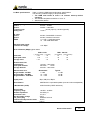
NARDA Safety Test Solutions S.r.l. Socio Unico Sales & Support: Via Leonardo da Vinci, 21/23 20090 Segrate (MI) - ITALY Tel.: +39 02 2699871 Fax: +39 02 26998700 Manufacturing Plant: Via Benessea, 29/B 17035 Cisano sul Neva (SV) Tel.: +39 0182 58641 Fax: +39 0182 586400 http://www.narda-sts.it User’s Manual PMM 7000 EMISSION PRECOMPLIANCE SYSTEM 150 kHz - 1000 MHz SERIAL NUMBER OF THE INSTRUMENT You can find the Series Number on the rear panel of the instrument. Series Number is in the form: 0000X00000. The first four digits and the letter are the Series Number prefix, the last five digits are the Series Number suffix. The prefix is the same for identical instruments, it changes only when a configuration change is made to the instrument. The suffix is different for each instrument. Document 7000EN-10407-1.66 – Copyright © NARDA 2007 NOTE: ® Names and Logo are registered trademarks of Narda Safety Test Solutions GmbH and L3 Communications Holdings, Inc. – Trade names are trademarks of the owners. If the instrument is used in any other way than as described in this Users Manual, it may become unsafe Before using this product, the related documentation must be read with great care and fully understood to familiarize with all the safety prescriptions. To ensure the correct use and the maximum safety level, the User shall know all the instructions and recommendations contained in this document. This product is a Safety Class I and Installation Category II instrument according to IEC classification and has been designed to meet the requirements of EN61010-1 (Safety Requirements for Electrical Equipment for Measurement, Control and Laboratory Use). This product has a Pollution Degree II normally only non-conductive pollution occurs. Occasionally, however, a temporary conductivity caused by condensation must be expected. The information contained in this document is subject to change without notice. KEY TO THE ELECTRIC AND SAFETY SYMBOLS: You now own a high-quality instrument that will give you many years of reliable service. Nevertheless, even this product will eventually become obsolete. When that time comes, please remember that electronic equipment must be disposed of in accordance with local regulations. This product conforms to the WEEE Directive of the European Union (2002/96/EC) and belongs to Category 9 (Monitoring and Control Instruments). You can return the instrument to us free of charge for proper environment friendly disposal. You can obtain further information from your local Narda Sales Partner or by visiting our website at www.narda-sts.it . Warning, danger of electric shock Earth Read carefully the Operating Manual and its instructions, pay attention to the safety symbols. Unit Earth Connection Earth Protection Equipotential KEY TO THE SYMBOLS USED IN THIS DOCUMENT: The DANGER sign draws attention to a potential risk to a person’s DANGER safety. All the precautions must be fully understood and applied before proceeding. WARNING The WARNING sign draws attention to a potential risk of damage to the apparatus or loss of data. All the precautions must be fully understood and applied before proceeding. CAUTION The CAUTION sign draws attention against unsafe practices for the apparatus functionality. NOTE: II The NOTE draw attention to important information. Note and symbols Contents General safety considerations and instructions........… EC Conformity Certificate………………………………….. Page VI VII 1 General Information 1.1 Documentation.............................................................. 1.2 Instruction Manual changes.......................................... 1.3 Introduction to PMM 7000............................................. 1.4 System composition..................................................... 1.5 PMM 7000 Optional accessories.................................. 1.6 Main specifications....................................................... 1.7 Front panel………………………………………………… 1.8 Emission measurements.............................................. Page 1-1 1-1 1-1 1-1 1-2 1-3 1-5 1-6 2 Installation 2.1 Introduction................................................................... 2.2 Initial inspection............................................................ 2.3 Packing and unpacking................................................ 2.4 Preparation for use....................................................... 2.5 Installation check list.................................................... 2.6 Line voltage selection............................................…… 2.7 Power cable............................................................….. 2.8 Environment..........................................................…... 2.9 Return for service................................................…..... 2.10 Equipment cleaning……………………………………. 2.11 Receiver installation.............................................….. 2.12 Handle positioning……………………………………… 2.13 Software installation.............................................….. 2.14 Dangerous input signals............................................ 2.15 Using Artificial mains................................................. 2.16 Using Voltage probe.................................................. 2.17 Using Clamp.............................................................. 2.18 Using Antenna........................................................... Page 2-1 2-1 2-1 2-1 2-1 2-1 2-2 2-2 2-2 2-2 2-2 2-2 2-3 2-5 2-5 2-5 2-5 2-6 Contents III 3 PMM 7000 receiver operation 3.1 PMM 7000 Receiver Operation................................. 3.2 Program startup......................................................... 3.2.1 Demo program........................................................ 3.3 Program operation..................................................... 3.4 File Manager.............................................................. 3.4.1 Save........................................................................ 3.4.2 Load........................................................................ 3.4.3 Compare................................................................. 3.5 Print........................................................................... 3.6 Make Report.............................................................. 3.7 Redraw....................................................................... 3.8 Dynamic 80/120 dB.................................................... 3.9 Comment................................................................... 3.10 Conducted emission................................................... 3.10.1 SETUPs................................................................. 3.10.2 Setup REMark....................................................... 3.10.3 Frequency setting.................................................. 3.10.4 Lisn........................................................................ 3.10.5 Min. ATT................................................................ 3.10.6 Limits..................................................................... 3.10.7 Limit Offset............................................................ 3.10.8 Make Limit............................................................. 3.10.9 Detectors............................................................... 3.10.10 Measure............................................................... 3.10.11 Worst 10 Pks....................................................... 3.10.12 Quit...................................................................... 3.11 Radiated emission.................................................... 3.11.1 Creating an antenna factor table........................... 3.12 Radiated power emission......................................... 3.13 Start Measure........................................................... 3.14 Pause Measure........................................................ 3.15 Stop Measure........................................................... 3.16 Zoom Mode.............................................................. 3.17 Spectrum Mode........................................................ 3.18 Manual Mode........................................................... 3.18.1 Selecting parameters………………………………. 3.18.2 Reference level………………………………….….. 3.18.3 Detector……………………………………………… 3.18.4 Demodulator………………………………………… 3.18.5 Lines/Antenna factor……………………………….. 3.19 Color selection......................................................... 3.20 Help.......................................................................... 3-1 3-1 3-2 3-5 3-5 3-6 3-8 3-8 3-8 3-9 3-10 3-10 3-11 3-12 3-13 3-13 3-13 3-13 3-13 3-13 3-14 3-14 3-17 3-17 3-18 3-18 3-18 3-19 3-21 3-22 3-22 3-22 3-22 3-23 3-24 3-24 3-25 3-25 3-25 3-25 3-26 3-26 4 Technical description 4.1 Principle of operation................................................. 4-1 5 Technical maintenance 5.1 Calibration check........................................................ 5.2 Safety fuse substitution.............................................. 5.3 Device cleaning recommendations............................. 5-1 5-1 5-1 IV Contents Figures Figure 1-1 4-1 Page Front and rear panel.......................................... PMM 7000 Block Diagram................................. 1-5 4-1 Tables Table 1-1 Page Main Specifications............................................ 1-3 Contents V SAFETY RECOMMENDATIONS AND INSTRUCTIONS This product has been designed, produced and tested in Italy, and it left the factory in conditions fully complying with the current safety standards. To maintain it in safe conditions and ensure correct use, these general instructions must be fully understood and applied before the product is used. • When the device must be connected permanently, first provide effective grounding; • If the device must be connected to other equipment or accessories, make sure they are all safely grounded; • In case of devices permanently connected to the power supply, and lacking any fuses or other devices of mains protection, the power line must be equipped with adequate protection commensurate to the consumption of all the devices connected to it; • In case of connection of the device to the power mains, make sure before connection that the voltage selected on the voltage switch and the fuses are adequate for the voltage of the actual mains; • Devices in Safety Class I, equipped with connection to the power mains by means of cord and plug, can only be plugged into a socket equipped with a ground wire; • Any interruption or loosening of the ground wire or of a connecting power cable, inside or outside the device, will cause a potential risk for the safety of the personnel; • Ground connections must not be interrupted intentionally; • To prevent the possible danger of electrocution, do not remove any covers, panels or guards installed on the device, and refer only to NARDA Service Centers if maintenance should be necessary; • To maintain adequate protection from fire hazards, replace fuses only with others of the same type and rating; • Follow the safety regulations and any additional instructions in this manual to prevent accidents and damages. VI Safety Consideration EC Conformity Certificate (in accordance with the directives: EMC 89/336/EEC and low voltage 73/23/EEC) This is to certify that the product: PMM 7000 Emission Precompliance System 150 kHz - 1 GHz Produced by: NARDA Safety Test Solutions Via Benessea 29/B 17035 Cisano sul Neva (SV) - ITALY complies with the following European Standards: Safety: CEI EN 61010-1 (2001) EMC: EN 61326-1 (2007) This product complies with the requirements of the Low Voltage Directive 73/23/EEC, amended by 93/68/EEC, and the EMC Directive 89/336/EEC amended by 92/31/EEC, 93/68/EEC, 93/97/EEC. NARDA Safety Test Solutions EC Conformity VII This page has been left blank intentionally VIII Safety Consideration 1 - General Information 1.1 Documentation Enclosed with this manual are: • a service questionnaire to send back to NARDA in case of equipment service is needed • an accessories check list to verify all accessories enclosed in the packaging. 1.2 Instruction Manual changes Instruments manufactured after the printing of this manual may have a serial number prefix not listed on the title page; this indicates that instruments with different Serial Number prefix may be different from those documented in this manual. 1.3 Introduction to PMM 7000 The PMM 7000 receiver is an Emission Precompliance System for measuring conducted and radiated interferences in the 150 kHz to 1000 MHz frequency range. This measurement system has been designed for use on any PC with the Windows™ operating system. Measurements taken with the PMM 7000 are in accordance with the various regulations regarding conducted emissions: FCC, VDE, CISPR, EN (Euronorm). The PMM 7000 pre-compliance measurement system allows the designer to measure the conducted and radiated interferences of a prototype under test as part of the daily routine. 1.4 System composition The PMM 7000 system is composed of the following components: - 150 kHz - 1000 MHz EMI receiver with 16 A artificial mains built-in; - Serial cable with 9/25 pin adapter; - Software CD-ROM; - Power cable; - LISN cable; - USB-RS232 serial converter - N-BNC Adapter - Operating manual; - Certificate of compliance; - Return for Repair Form. Document 7000EN-10407-1.66 - © NARDA 2007 General Information 1-1 1.5 PMM 7000 Optional accessories 1-2 The following can be ordered as options: • • • • • • • • • • • L1-150 Network L3-25 artificial mains ( three-phase, 25 A); L3-64 artificial mains ( three-phase, 64 A); L3-100 artificial mains ( three-phase, 100 A); L2-D, VNET-150 artificial mains; PL-01 pulse limiter; SHC-1 or SHC-2 high current voltage probes; AS-01 antenna set; EMCO 7405 low frequency probe set for electrical and magnetic fields; Van Veen loop antenna for lamp measurements; TRF-1 balanced/unbalanced transformers;. General Information 1.6 Main specifications Table 1-1 lists the PMM 7000 performance specifications. The following conditions apply to all specifications: • The PMM 7000 needs at least a 15 minutes warm-up before operating. • The ambient temperature shall be 5° to 40° C. • Altitude Max 2000 m TABLE 1-1 Electrical characteristics Frequency range Input A Input B Frequency step Setting error 150 kHz - 30 MHz 30 MHz - 1000 MHz 10 kHz (input A), 100 kHz (input B) <1x10⁻⁶ RF input Input A Input B VSWR 50 Ohm, female BNC connector 50 Ohm, female N connector < 1.2 with ≥ 10 dB attenuation < 2 with 0 dB attenuation Maximum input signal sinewave AC voltage <127 dBµV Noise indication (dBµV) typical values Peak value Quasi-peak value Average value BW = 9 kHz ( 150 kHz-1MHZ) (1-30 MHz) < 20 <8 < 16 <4 < 10 <2 Measurement time Peak detector Quasi-peak detector Average detector Measurement error Range 150 kHz - 30 MHz Range 30 MHz - 300 MHz Range 300 MHz - 1000 MHz BW = 120 kHz (30-300 MHz) 12 10 8 (300-1000 MHz) 14 12 10 10 msec - 1000 msec 200 msec 10 sec 20 msec - 1000 msec Guaranteed ± 2 dB + 2 - 3 dB + 2 - 4 dB Typical ± 2 dB ± 2 dB ± 2 dB Display units dBµV, dBµV/m, dBpW Demodulation AM/FM with incorporated speaker (tone and volume adjustable) IF Bandwidths (-6 dB) 9 kHz/120 kHz (CISPR tolerance) Internal LISN Frequency range Network impedance Continuous I out Max AC supply voltage EUT power plug Artificial hand & protective earth Pulse limiter 150 kHz - 30 MHz 50 Ω//50 µH 2 x 16 A 250 V SCHUKO 10/16 A built-in built-in General Information 1-3 Power supply AC Frequency Power Fuse 115/230 VAC ± 10% user selectable 50/60 Hz 30 VA Max (250 V) T 125 mA (115 V) T 250 mA General data Interface Operating temperature Operating Humidity Max Storage temperature RF suppression Dimensions Weight 1-4 General Information RS-232 (9 pin) 5 - 40°C 80 % -25 - +75°C in conformity with CISPR 22 364 x 120 x 376 mm (W x H x D) 5 kg 1.7 Front and rear panel Fig. 1-1 Views of front and rear panels Legend: 1) Power LED 2) TX/RX leds 3) Loud speaker 4) RF input - 30 MHz - 1 GHz 5) RF input - 150 kHz - 30 MHz 6) Line 1 led 7) Line 2 led 8) EUT power plug 9) Ground Plug 10) Artificial hand 11) Power switch 12) Ground plug 13) EUT power supply plug 14) RS232 connector 15) Safety fuse/power switch 16) Main power plug General Information 1-5 1.8 Emission measurements All electric, electromechanical and electronic devices are potential generators of electromagnetic interference (EMI). The term EMI thus refers to the electromagnetic fields emitted by a device which propagate themselves along cables or through the air and couple with other devices that are present in the surroundings. These electromagnetic fields (conducted noise or radiated interference) coupling with nearby equipment can cause possible malfunctions. Today, thanks to international standards (IEC) and the European directives implemented by the member states of the European community, product commercialisation is subject to the measurement of this interference, which must be within well defined limits. The philosophy used for the PMM 7000 was that of developing a simple and reliable system of measurement for classifying or inspecting any electric or electronic device from the first stages of design. The mandatory measurement of emitted noise obliges equipment constructors to respect the limits foreseen by basic standards or specified for each product category. The PMM 7000 receiver is the ideal solution for prototype debugging and periodical production testing. The recommendations and standards in force specify the measurement criteria, the environment for carrying out tests and the instrumentation to be employed; this is so that everyone can perform the same measurement with the same results. The PMM 7000 control software permits rapid use of the instrument without any special difficulties. All operations, calculations and preparations are made automatically. Thus, the operator can concentrate just on analysing the measurement results. The PMM 7000 hardware has also been designed for rapid and easy installation on any PC with the Windows™ operating system and with at least one free serial port. The typical objective in using the PMM 7000 EMI receiver is that of measuring, frequency by frequency, the maximum noise emitted by equipment under test in the 150 kHz to 1000 MHz frequency range. The standards also specify that the measurement environment should have a reference plane or ground plane. The device under test (DUT) must be installed according to the procedures indicated in the constructor’s manual and normal operating conditions respected. 1-6 General Information 2 - Installation 2.1 Introduction This section provides the information needed to install your PMM 7000. Included is information pertinent to initial inspection, power requirements, line voltage and fuse selection, power cables, interconnection, environment, instrument mounting, cleaning, storage and shipment. 2.2 Initial inspection A WARNING 2.3 Packing and Unpacking To avoid hazardous electrical shock, do not turn on the instrument when there are signs of shipping damage to any portion of it. Inspect the shipping container for damage. If the shipping container or cushion material is damaged, it should be kept until the contents of the shipment have been checked for completeness and the instrument has been checked mechanically and electrically. Verify the accessories availability in the shipping referring to the accessories check list enclosed with the Users Manual. Notify any damage to the carrier personnel as well as the NARDA Representative. 2.4 Preparation for use A WARNING This is a Safety Class I equipment, it is provided with a protective earth terminal. An uninterruptible safety earth ground must be provided from the main power source to the product input wiring terminals through the power cable (or supplied power cable set). Verify the safety earth ground functionality before operation. 2.5 Installation Check list Before operation the following steps shall be taken: • Check the line voltage to ensure the compatibility with the equipment settings. • Verify that the fuse rating is appropriate for the line voltage used. A WARNING 2.6 Line voltage selection A WARNING Before plugging PMM 7000 into the main supply line ensure that the line voltage is in the range specified, and that the appropriate fuse have been selected. PMM 7000’s power supply voltage is factory set at 230 VAC. To change the PMM 7000’s power supply voltage it is necessary to rotate the power switch, located on the rear panel, to the desired voltage. Before connecting this instrument, ensure that an uninterruptible safety earth ground is provided from the main power source to the product protective earth connection. If this instrument is to be connected to other equipment or accessories, prior to energizing either unit verify that a common ground exists between them. Any interruption or loosening of the protective earth ground conductor, either inside or outside the unit or in an extension cable will cause a potential shock hazard that could result in personal injury. Document 7000EN-10407-1.66 - © NARDA 2007 Installation 2-1 2.7 Power cable This instrument is equipped with a three wires power cable. When connected to an appropriate AC power receptacle, this cable grounds the instrument chassis. 2.8 Environment The operating environment is specified to be within the following limitations : +10° to +40° C • Temperature < 90% relative • Humidity 4000 meters • Altitude The instrument should be stored in a clean, dry environment The storage and shipping environment is specified to be within the following limitations : -40° to + 50° C • Temperature < 95% relative • Humidity 15000 meters • Altitude 2.9 Return for service If the instrument should be returned to NARDA for service, please complete the service questionnaire enclosed with the Users Manual and attach it to the instrument. To minimize the repair time, be as specific as possible when describing the failure. If the failure only occurs under certain conditions, explain how to duplicate the failure. If possible, reuse of the original packaging to ship the equipment is preferable. In case other package should be used, ensure to wrap the instrument in heavy paper or plastic. Use a strong shipping container and use enough shock absorbing material around all sides of the equipment to provide a firm cushion and prevent movement in the container. To prevent damage during shipment in particular protect the front panel. Seal the shipping container securely. Mark the shipping container FRAGILE to encourage careful handling. 2.10 Equipment cleaning Use a clean, dry, non abrasive cloth for equipment fan opening cleaning. To clean the equipment do not use any solvent, thinner, turpentine, acid, acetone or similar matter to avoid damage to external enclosure. 2.11 Receiver Installation The PMM 7000 receiver can only function if connected to a PC via the RS232 cable. The below procedure should be followed: • Connect RS-232 cable between PC and PMM 7000; • Plug in the PC and PMM 7000 power cables; • Switch on the PC and PMM 7000. The PMM 7000 needs at least a 15 minutes warm-up before operating When 7000 is on, you can see the L1 led blinking. This warns you that PMM 7000 is working properly. 2.12 Handle positioning To change the position of the handle, pull it in front of yourself and turn it up or down according to the wished position. In order to use the built-in artificial mains an isolating transformer must be placed between the main power and the LISN. This is to avoid the safety switches always being activated due to the high current dispersions of the LISNs themselves. 2-2 Installation 2.13 Software installation In order to use the PMM 7000 all of the files contained on the supplied CDROM must be installed. Follow the procedure below: • switch on the PC and launch the Windows operating system. • insert the PMM 7000 CD-ROM in the CD drive; • invoke the “Run” function from the Program Manager • enter the command “A:SETUP” and press <Enter>. During the installation phase, the program will request confirmation of the directory on which the files are to be installed. Reply with Continue if you wish to confirm the directory 7000, otherwise type in a new name. The screen display will be similar to the following: Click on the Continue button to continue with the installation procedure, or Exit Setup to abort it. Near the end of the installation procedure the program will ask if the demonstration program is also to be installed. The display will be: Reply with OK to install the software demo. Installation 2-3 Normally the program automatically identifies the serial port that the receiver is connected to. If you wish to force the use of a specific port, the following procedure should be used: • • • • activate the Program Manager invoke the Proprieties command type on the command line: 7000.exe COMM=N where N indicates the serial port to use The PMM 7000 software is composed of various files, some are only accessible to the user (e.g. Header.TXT) after their installation while others, although indispensable for correct system operation, are totally transparent to the operator. 2-4 Installation 2.14 Dangerous input signals Note: noise produced by equipment under test can be extremely dangerous for the receiver’s input stage, even if not shown on the PMM 7000 screen. It is possible, in fact, to have an associated frequency outside the receiver’s measurement range but with a very high energy content that can damage the PMM’s 7000 input stage. If you have some doubt about the amplitude of your signal, use an external attenuator or measure it with an oscilloscope before connecting it to the receiver. 2.15 Using Artificial mains To acquire and measure conducted noise on power cables of any type of electrical or electronic device it is necessary to use an artificial mains (LISN) inserted between the mains and the device in question. The LISN employed must conform to CISPR-16 standards. PMM 7000 include an internal LISN up to 16A. A WARNING In order to use the artificial mains an isolating transformer must be placed between the mains and the LISN. This is to avoid the safety cutout always being activated due to the high current dispersions of the mains themselves. The PMM 7000 receiver is automatically connected to his 16 A, internal artificial mains. Noise measurement on each single phase and neutral is automatically switched via software. Alternatively, it is necessary to use manual switches located on the various LISNs. Consult the operating manual of the artificial mains employed for further details. 2.16 Using Voltage probes The voltage probe must be used when measurements are made at terminals other than mains ones, such as the load or command terminals for example. The voltage probe can also be used on power supply terminals when the V type artificial mains (e.g. L3-32 or L3-64) cannot be used without excessively influencing the equipment under test or when a LISN of adequate power is unavailable. The voltage probe contains a resistor with a minimum resistance of 1500 ohm, in series with a capacitor of insignificant reactivity in ratio to the resistance (in the 150 kHz to 30 MHz range). See art. 12 of CISPR Publication 16. Measurements must be corrected in accordance to the voltage split between the probe and the measurement equipment. NARDA offers two probes with attenuation of 30 or 35 dB for currents up to 1500A. The probe’s attenuation value is specified in the PMM 7000 software by entering the Setup menu and clicking on the EXT button. See section 3.12. 2.17 Using Clamp The absorbing clamp is used to define radiated emissions from power cables and I/O cables. The clamp should be connected, through a suitable coaxial cable, to the receiver’s RF N connector input. Position your EUT on table or at floor depending upon the installation given to the end user. Make sure to load the correction table according to the clamp used. Position the clamp over the slide bar and take several measurement at different clamp positions. At the end of this process to calculate the worst case. All values must be below the limit. Installation 2-5 2.18 Using antenna When you use one or more antennas, or near field probes, you should load the antenna factors to a PMM 7000 file. In this way PMM 7000 will correct the absolute measurement adding or subtracting the correction factors frequency by frequency (see applicable software section). The antenna factors of the our standard antenna are already pre-loaded In the software; simply load the appropriate file. When you use two different antennas (i:e: Biconic and Log-periodic), Kfactor table automatically takes into account correction factors and software prompt advises the operator to change antenna, pausing in the meantime measurement. Once finished the sweep, PMM 7000 will combine the two measurements into a single graph. 2-6 Installation 3 - Operation 3.1 PMM 7000 receiver operation Safety Precautions Before running the program, ensure that the PMM 7000 measurement system is correctly connected and switched on. Check the serial connection between the PC and the receiver. 3.2 PMM 7000 program start-up The PMM 7000 receiver has been designed for quick and easy operation, even by inexperienced personnel. If the program has been correctly installed, the Program Manager will display the following window: Double-click on the “7000 FOR WIN” icon to activate PMM 7000 receiver operation. Document 7000EN-10407-1.66 - © NARDA 2007 Operating Instruction 3-1 3.2.1 Demo program To run the demonstration program, simply double-click on the DEMO WIN 7000 icon. All of the PMM 7000 commands can be activated without having the receiver connected to the PC. This program is particularly useful for learning to use the receiver, preparing measurement set-ups or writing test reports without connecting the receiver to the PC. Once launched via the run command, a window indicating the software release, issue date and PC port used will be displayed for a few seconds, after which the PMM 7000 main menu will be shown. The screen display will be similar to the following: To exit the program, just click on the top left-hand corner. The software will display a confirmation window for exiting the program. Click on the OK button to close the 7000 WIN for Windows application. 3-2 Operating Instruction If serial cable is not connected or if 7000 is not turned on you will get the following message: Respond OK and try again after checking RS232 connection and power to PMM 7000. If no serial ports are available, the following message is displayed: Operating Instruction 3-3 If during normal operation the serial cable is disconnected or PMM 7000 is turned off you get the following display: To connect the serial cable or turn on PMM 7000 to establish communication to PC. 3-4 Operating Instruction 3.3 PMM 7000 program operation Software for the PMM 7000 receiver has been designed for use also by personnel who are not Windows™ experts. It is necessary however to have some familiarity with handling files and Windows. The monitor screen is usually divided into three parts. The upper part, consisting of one line, contains the main commands. The central part is assigned to measurement display. The lower part of the screen indicates certain useful operational information such as the detector or LISN in use, comment lines etc. When the mouse is moved onto a command (button) a brief help caption describing the command is immediately shown for a few seconds. 3.4 File Manager The PMM 7000 File Manager permits the setup files and graph files o measurements taken to be saved, compared and loaded. Use the following button to save files : Operating Instruction 3-5 3.4.1 Save Files When this command is activated it invokes the Windows™ File Manager which will open the following window : Enter the name of the file and click on the OK button. All measurement files have the extension .FS7. It is possible to save measurement setups or other file types by clicking on the “Type of Files” window. The various options are shown in the following screen display: The file types are: .FS7 .BMP .TXT save measurement graphs save graphs in the BitMap format; save graphs in the form of ASCII character tables If it is attempted to save a file using the name of a pre-existing one, the following will be displayed: 3-6 Operating Instruction Reply with Yes to overwrite the existing file, or No to abort the operation. Operating Instruction 3-7 3.4.2 Load files Use the following button to load or compare previously saved files : Clicking on this button results in the following display: Choose the file that is to be loaded and click on the OK button. 3.4.3 Compare It is possible to compare files already stored on hard disk; you can load up to two files. The first should be loaded without using Compare function, the second must be loaded with Compare enabled. Or, you can show one stored measurement and compare it with the current graph. The colours of the two traces are user definable. See section 3.19 To cancel files that are no longer required the Windows™ File Manager should be run and supplied with the appropriate commands. 3.5 Print Click on the following button to print out the measurements taken: When this command is activated it invokes the Windows™ Print Manager, after which all the normal functions for managing document printing will be operative. 3-8 Operating Instruction 3.6 Make Report The Make Report command allows the creation of test reports. The software will create a table showing all frequencies where the limit are above an amount specified by “Limit Offset” defined by during setup. Clicking on this button will display a window similar to the following: This results table can be printed with the internal Print command or saved as a text file, i.e. in ASCII. If you are using a negative limit offset the report will take in account all levels below the limit. Selecting the “Save as Text” command opens a window similar to that below: Operating Instruction 3-9 Type your wished file name and press OK. All report files have the .RPT extension. If you try to make a report without loading any limits you get the following error message: Push OK and enter setup menu by loading one limit. This command serves for canceling old data displayed on screen and redrawing the screen image or for obtaining the envelope of two or more graphs when using a LISN with measurements on more than one line (e.g. L1+L2). 3.7 Redraw Sometimes this command is used to refresh the screen due to Windows™ problem or not enough memory available mainly when you switch from one Windows application to another and then you go back to 7000 software. 3.8 Dynamic 80/120 dB The Dynamic command allows the measurement’s full-scale reading to be toggled between 80 and 120 dB. Using 80 dB full scale will increase your display resolution. 3-10 Operating Instruction 3.9 Comment Comment lines can be added via the Comment button. The program will add a window at the bottom of the graph where comments can be written. The comment window only displays two lines at a time, but it is possible to write up to 300 characters (including “space” and “c/r”). Use the keyboard’s up and down arrow keys to show other lines not displayed. The screen display will resemble : If you try to write more than 300 characters you will obtain the following warning message: Operating Instruction 3-11 3.10 Conducted emission To perform conducted measurement you should push the following button Activating it, you automatically enter the setup menu for defining all measurement parameters. Pushing Measure you will start the measurement with the parameters assigned by default. The SetUP 7000 menu is divided into several parts. The actions performed are: 3-12 Operating Instruction 3.10.1 SETUPs Usually PMM 7000 uses the Default setup where the Limit is not assigned. Therefore you must load a limit and define which mains line should be measured and which detector should be used before starting the measurement. If you wish to save your own configuration you must define measurement parameters first (Start, Stop and Step frequency; LISN, Limit, Detector and measurement time, Minimum Attenuator, Limit offset), then select SETUPs buttons from 1 to 9 and push SAVE button. To recall for a specific set-up, push one of the 9 buttons where you loaded the set-up you wish to use. 3.10.2 Setup REMark If you wish to remember to which configuration is used for, you can type a note using Setup REMark line. This message will be always displayed each time you recall such configuration. 3.10.3 Frequency setting This area is used to select Start, Stop and Step frequency. Minimum Start is 150 kHz, maximum Stop is 30 MHz. Minimum Step is 10 kHz. If you try to type any frequency values lower than 150 kHz or higher than 30 MHz, PMM 7000 will display an warning message. 3.10.4 Lisn This area is used to select phase o neutral line (L1 or L2 buttons); to select protective earth (P.E.); to select L1 + L2 mode of operation (PMM 7000 will perform measurements on both lines and will give the worst case envelope); to select an external LISN or voltage probe usage, in this case you must assign the attenuation value associated with this specific probe. 3.10.5 Min. ATT. This area is used to select the internal attenuator. If you do not know the noise level emitted by your equipment under test, the 10 dB attenuation is always recommended. Then if you find the signal to be very small you can repeat the measurement with 0 dB. 3.10.6 Limits Limits function is used to select which limit should be shown on the screen. The company service have already pre-loaded several limits according to most used standards. Clicking on the arrow button gives access to the list of pre-loaded Limits. Operating Instruction 3-13 3.10.7 Limit Offset: This function is used to perform the report. You should assign a value to be compare with the limit. All frequencies where the levels are above such amount will be showed into report table. If you use a negative number you get all frequencies where the levels are below the limit. The example below offers the display how a typical report is shown The report can be printed or saved into a file with text format. You can use any Windows™ application to further manipulate PMM 7000 measurement file. 3.10.8 Make Limit 3-14 This command is used to create or modify a limit. Clicking on the Limit button gives access to a special editor for creating and/or modifying limits. The screen display will resemble the following: Operating Instruction To assign frequency and level values just click on the desired row with the mouse and directly type the frequency value or level in dB. Rows in the table relative to a specific limit can be deleted with the Remove Row command. The Clear TAB command permits a limit that is no longer used to be canceled. Before canceling the limit, the program displays the following confirmation prompt: An OK reply will effectively cancel the limit. The Graph command, instead, is used to define the limits in a graphical manner. The program displays a window showing the frequency and level indicated by cross-wires. Clicking on the ADD button adds the point to the limit table under construction. Step by step, move the cross-wires with the mouse to a certain point on the screen that has the desired frequency and level and then click on the ADD button to add the point to the table. The screen display will be similar to the following: Operating Instruction 3-15 Click on the Back to Table button to automatically pass from the graphical layout back to the tabular format for the current table. The Exit command exits the limits editor. When a limit has been created, whether in tabular or graphical form, it should be saved using the Save command. Clicking on Save enters the File Manager for assigning a name to the file to be saved. All limit files have the .Lim extension. The screen display will resemble the following : Clicking on Load will cause the File Manager to display all the limit files available for loading. The display will resemble the following: Select the limit you are interested for and push OK. 3-16 Operating Instruction 3.10.9 Detectors This area is used to define which detector should be used. Possible choices are: Peak, Average, Q.Peak and Peak+Q.Peak. Peak+Q.Peak function will be active only when one limit is selected. After selecting the detectors you can apply for measurements time. Fastest mode of operation is to use Peak detector with 10 msec measurement time for each frequency step. Since PMM 7000 has three detectors you can activate them simultaneously. Be aware that Peak detector is always on. PMM 7000 has a special circuit to detect if the input signal is to high. If that happens some intermodulation products (harmonics) will be produced with the result that phantom frequencies are displayed on the screen not produced by the EUT. If you click on the “Detect compression” box, PMM 7000 will enable this circuit and display a warning message each time the phenomena happens. When the input signal is too high (typically greater than 70/80 dBµV the display will show the following warning message: Answer Yes to pass into semi-automatic mode (the internal attenuator will be kept to the higher setting) or push Cancel to proceed with automatic attenuator selection. 3.10.10 Measure To start the measurements. Operating Instruction 3-17 3.10.11 Worst 10 Pks to perform continuous measurements highlighting the worst 10 points. When this function is activated the display will be similar to the following: For every sweep PMM 7000 increases an internal counter and display the number of sweeps performed into a window located on center of the second line of the main menu. (I.E. W(9) indicates the 7000 performed 9 measurements. Refer to section 3.18 how to use this mode of operation. to exit the setup menu and to go back to main menu. 3.10.12 Quit 3.11 Radiated emission To perform radiated measurements you should push the following button: Activating it, you automatically enter the setup menu for defining all measurement parameters. The display will be: Make sure to use the 30 MHz - 1 GHz input (N connector). If you are using an antenna, do not forget to load the file containing the antenna factor. If not, use the command Make Antenna to create the appropriate correction file. All other mode of operations and command are the same as for conducted measurements. See 3.10 3-18 Operating Instruction 3.11.1 Creating an antenna factor table Clicking on the Antenna button gives access to a special editor for creating and/or modifying antenna factor table. The display will resemble the following: To assign frequency and attenuation/gain values just click on the desired row with the mouse and directly type the frequency value or level in dB. If you are using two antennas (i.e. PMM antenna set AS-01), you must use the Freq Switch function to pause the measurement and change the antenna. To enter the Freq Switch window and type the frequency required to pause 7000 enabling you to change the antenna. All other modes of operation and commands are similar to Limit creation. See Limit section (3.10.8). When PMM 7000 reaches the frequency established by Freq. Switch, you get new warning message to change the antenna. Operating Instruction 3-19 3-20 Operating Instruction 3.12 Radiated power emission To perform radiated power measurements you should push the following button: Activating it, you automatically enter the setup menu for defining all measurement parameters. The display will be: Make sure to use the 30 MHz - 1 GHz input (N connector). If you are using a clamp, do not forget to load the file containing the correction factor. If not, use the Make CLAMP to create the specific table. All other mode of operation and commands are the same as for conducted or radiated measurements. Operating Instruction 3-21 3.13 Start Measure Measurement is started via the following button: Clicking on this button starts measurements with the parameters specified on the setup. 3.14 Pause Measure It is possible to suspend the receiver during the signal acquisition phase and thus temporarily stop measurement by clicking on the following button: When this button is clicked on again, the receiver will recommence measurement from where interrupted. 3.15 Stop Measure To terminally interrupt acquisition click on the Stop button: Clicking on Stop conserves all previously acquired data. The graph can be saved and printed even if the measurement is incomplete. 3.16 Zoom Mode The Zoom command is used to enlarge a portion of the graph: Activating the Zoom opens a window containing an enlarged portion of the graph. The window’s position can changed by dragging it with the mouse to the desired location; both vertically and horizontally. The screen display will be similar to the following: The window’s central frequency can be changed by clicking on the two arrows (left or right) or by positioning the mouse on the part of the graph to be expanded. Note: the central frequency and Span are displayed on the lower part of the screen. The central frequency can be set by entering the Center Frequency window and typing in the desired value, from 150 kHz to 1000 MHz, via the keyboard. On the left top corner is displayed the level value of signal at center frequency. 3-22 Operating Instruction 3.17 Spectrum Mode The PMM 7000 receiver can also be used as a spectrum analyzer with some limitation. Clicking on the button activates the Spectrum mode, which permits the operator to detect any changes at a defined frequency whilst the measurement is in course. In this mode of operation the receiver always uses the peak detector. The Spectrum menu is shown in the following screen display: To change the Reference Level, just move the spectrum window up an down using mouse. Operating Instruction 3-23 3.18 Manual Mode With the aid of the Manual Mode command, the operator is able to carry ou signal at a certain frequency like a selective voltmeter. A digital display and analogic indicator, also with max. hold function, indicate the measured signal’s level. After clicking on the button and entering Manual Mode the following screen display will appear : The measured readings will be more accurate if the level indicator remains in the green zone. 3.18.1 Selecting parameters The following can be set in the PARAMETER area: Frequency for specifying the tuning frequency, expressed in kHz or MHz as a whole number or with two decimal places. Fine tuning is possible via the arrow buttons. Step for defining the frequency steps to be used when increasing or reducing the central frequency. Minimum value is 10 kHz for frequencies below 30 MHz and 100 kHz for frequencies over 30 MHz. 3-24 Operating Instruction 3.18.2 Reference Level It is possible to set the receiver’s input reference level between 50 dBµV and 120 dBµV. A high initial level (100 dBµV) is set by default to avoid accidental damage; for this motive the level must be carefully reduced, avoiding situations where the analogic indicator remains permanently in the upper part of the scale (OVERLOAD). Clicking on the button automatically sets up the best reference value according to the measured level. 3.18.3 Detector Selection can be made between Peak (instantaneous), Q.Peak (CISPR quasi-peak) and Average (mean). The user can activate all detectors simultaneously but Peak should be always on. Obviously, a Peak measurement will give pessimistic results compared to a Q.Peak or Average measurement. 3.18.4 Demodulator By inserting the AM or FM demodulator it is possible to listen to the modulating noise of a certain carrier over the speaker. This helps the operator in identifying the source of the noise, internal or external to the device under test (DUT). With the sliding control switch you can adjust the tone or the volume. 3.18.5 Lines/antenna factor Depending upon the selected mode of operation the menu offers to chose which line of the artificial mains is connected to the receiver or it shows the correction factor (of antenna or clamp) for all frequencies chosen. Operating Instruction 3-25 3.19 Color selection. It is possible to change the color of all parts of the graph pushing the following button: The screen display will resemble the following: Click on the box where the color is to be changed and select a new color. Press Save to save the new palette. Inside the Misc. Window you can define the format how to save your report. Possible choices are: Scientific or Standard. Reply with Yes to confirm save. By checking the Save setting box, the latest configuration will be saved in the default.pnl file. 3.20 Help 3-26 Clicking on the Help command opens a window with a brief description of the PMM 7000 software. Operating Instruction 4 - Technical description 4.1 Principle of operation PMM 7000 philosophy is based on the superheterodyne principle. By this principle any high frequency input signal, in a defined frequency range, is converted into a number of fixed lower intermediate frequency. The PMM 7000 diagram is shown below: PMM 7000 REV.1.1 03/06/97 I IF 310.7 MHz INPUT 30MHz-1GHz OVER PE3 MAX 127 dBuV RANGE II IF 139.3 MHz (-40 dBm) ATT.70dB STEP 10dB I IF 760.7 MHz 900MHz 450MHz (-30 dBm) INPUT 150kHz-30MHz MAX 127 dBuV 1 4 (-37 dBm) 1 760.85-1020.7 MHz 150MHz x2 1000.7-1310.7 MHz x3 IN EXT PLL PULSE 15MHz 1/10 LIMITER L1 1 MAX LPF550kHz L2 PE0 III IF 10.7 MHz 1 LPF 15 MHz hold BW 120 kHz RIV LOG Qp B/C-D Ct= Dt= Mt= BAND B-C/D MAX PE1 hold BW 9 kHz MAX AVG PE2 hold DET.RESET IV IF 455 kHz Demod. OUT BF AM/FM Fig. 4-1 PMM 7000 Block Diagram Document 7000EN-10407-1.66 - © NARDA 2007 Technical description 4-1 This page has been left blank intentionally 4-2 Technical description 5 - Technical maintenance INTERNAL CALIBRATIONS AND REPAIRS CAN ONLY BE CARRIED OUT BY AUTHORIZED TECHNICAL SUPPORT SERVICE. NARDA DECLINES ALL RESPONSIBILITY FOR PERSONAL OR MATERIAL DAMAGES CAUSED BY NON AUTHORIZED OPERATIONS ON INSTRUMENTS OR TAMPERING WITH THEM. 5.1 Calibration check Sine-Wave Voltage Accuracy Set in Manual mode with indication of Peak/Qpeak/Avg. Input a signal of 60dBuV. Check the readings at the frequencies listed in the test certificate. Pulse response peak and quasi peak Set in Manual mode with indication of Peak/Qpeak. Apply a 100 Hz pulsed signal, level 90dBuV/MHz. Measure Peak and Q-peak levels at 10MHz-100MHz. Spurious disturbance Set in Sweep mode with indication Peak. Terminate the input with a 50ohm load. Check the spurious levels at the frequencies listed in the test certificate. Residual noise Set in Manual mode. Terminate the input with a 50ohm load. Check the noise level (must be below the limits shown in the test certificate). IF bandwidth at -6 dB POINT Set in Manual mode with indication Avg. Input a signal of 10 MHz, level 60dBuV. Tune the center frequency up and down until reading 54dBuV. Check the correspondence with the IF filter bandwidth. Repeat at the frequency of 100MHz. (refer to the test certificate) 5.2 Safety fuse substitution A WARNING Disconnect the power cable before substituting the fuse. Only use replacement fuses of the same type and specification. The safety fuse is housed in a special receptacle located between the power cable connector and the power switch. A slow-blow 250 V type T 125 mA fuse is used for 230 V mains supply. A slow-blow 250 V type T 250 mA fuse is used for 115 V mains supply. 5.3 Device cleaning recommendations Use a clean, dry, non abrasive cloth for equipment fan opening cleaning. To clean the equipment do not use any solvent, thinner, turpentine, acid, acetone or similar substances when cleaning to avoid damaging silk-screen printing and/or plastic components. Document 7000EN-10407-1.66 - © NARDA 2007 Technical Maintenance 5-1 This page has been left blank intentionally 5-2 Technical Maintenance NARDA Safety Test Solutions S.r.l. Socio Unico Sales & Support: Via Leonardo da Vinci, 21/23 20090 Segrate (MI) - ITALY Tel.: +39 02 2699871 Fax: +39 02 26998700 Manufacturing Plant: Via Benessea, 29/B 17035 Cisano sul Neva (SV) Tel.: +39 0182 58641 Fax: +39 0182 586400 http://www.narda-sts.it Mod. 18-1 Caro cliente grazie per aver acquistato un prodotto NARDA! Sei in possesso di uno strumento che per molti anni ti garantirà un’alta qualità di servizio. NARDA riconosce l'importanza del Cliente come ragione di esistenza; ciascun commento e suggerimento, sottoposto all'attenzione della nostra organizzazione, è tenuto in grande considerazione. La nostra qualità è alla ricerca del miglioramento continuo. Se uno dei Suoi strumenti NARDA necessita di riparazione o calibrazione, può aiutarci a servirla più efficacemente compilando questa scheda e accludendola all’apparecchio. Tuttavia, anche questo prodotto diventerà obsoleto. In questo caso, ti ricordiamo che lo smaltimento dell'apparecchiatura deve essere fatto in conformità con i regolamenti locali. Questo prodotto è conforme alle direttive WEEE dell’Unione Europea (2002/96/EC) ed appartiene alla categoria 9 (strumenti di controllo). Lo smaltimento, in un ambiente adeguato, può avvenire anche attraverso la restituzione del prodotto alla NARDA senza sostenere alcuna spesa. Può ottenere ulteriori informazioni contattando i venditori NARDA o visitando il nostro sito Web www.narda-sts.it. Dear Customer thank you for purchasing a NARDA product! You now own a high-quality instrument that will give you many years of reliable service. NARDA recognizes the importance of the Customer as reason of existence; in this view, any comment and suggestion you would like to submit to the attention of our service organization is kept in great consideration. Moreover, we are continuously improving our quality, but we know this is a never ending process. We would be glad if our present efforts are pleasing you. Should one of your pieces of NARDA equipment need servicing you can help us serve you more effectively filling out this card and enclosing it with the product. Nevertheless, even this product will eventually become obsolete. When that time comes, please remember that electronic equipment must be disposed of in accordance with local regulations. This product conforms to the WEEE Directive of the European Union (2002/96/EC) and belongs to Category 9 (Monitoring and Control Instruments). You can return the instrument to us free of charge for proper environment friendly disposal. You can obtain further information from your local NARDA Sales Partner or by visiting our website at www.narda-sts.it. 5 Servizio richiesto: 5 Service needed: Solo taratura Calibration only Riparazione Repair Riparazione & Taratura Repair & Calibration Taratura SIT Certified Calibration Altro: Other: Ditta: Company: Indirizzo: Address: Persona da contattare: Technical contact person: Telefono: Phone n. Modello: Equipment model: Numero di serie: Serial n. 5 Accessori ritornati con l’apparecchiatura: Nessuno Cavo(i) Cavo di alimentazione 5 Accessories returned with unit: None Cable(s) Power cable Altro: Other: 5 Sintomi o problemi osservati: 5 Observed symptoms / problems: 5 Guasto: Fisso Intermittente 5 Failure: Continuous Intermittent Sensibile a : Freddo Sensitive to: Cold Caldo Heat Descrizione del guasto/condizioni di funzionamento: Failure symptoms/special control settings description: Se l’unità è parte di un sistema descriverne la configurazione: If unit is part of system please list other interconnected equipment and system set up: Vibrazioni Altro Vibration Other Suggerimenti / Commenti / Note: Suggestions / Comments / Note: