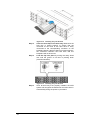
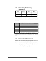
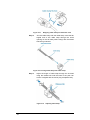
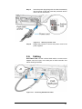
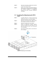
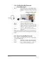
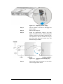
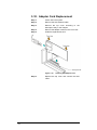
1
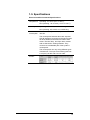
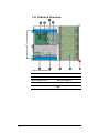
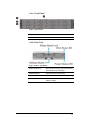
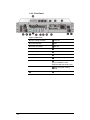
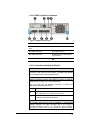
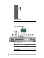
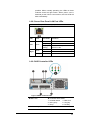
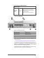
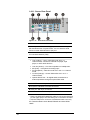
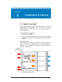
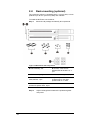
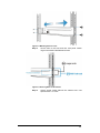
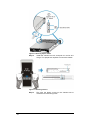
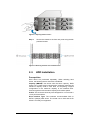
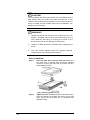
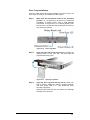
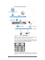
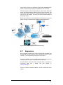
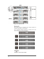
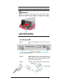
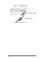
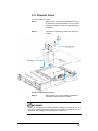
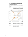
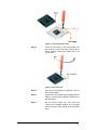
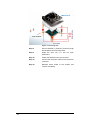
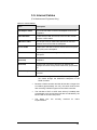
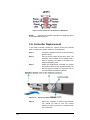
Version 1.0 (1, 2006) Technology Inc. NVR3000 Series Hardware User Manual January 08, 2009. rev. 1.1b Contact Information Surveon Technology Inc. 2F, No. 102, Sec. 3, Chung Shan Rd. Chung Ho City, Taipei Hsien 23544 Taiwan, R.O.C. Tel: +886-2-2226-2966 Fax:+886-2-2226-7128 Website: www.surveontech.com E-Mail: [email protected] Support: [email protected] Copyright 2009 This Edition First Published 2009 All rights reserved. No part of this publication may be reproduced, transmitted, transcribed, stored in a retrieval system, or translated into any language or computer language, in any form or by any means, electronic, mechanical, magnetic, optical, chemical, manual or otherwise, without the prior written consent of Surveon Technology Inc. Disclaimer Surveon Technology makes no representations or warranties with respect to the contents hereof and specifically disclaims any implied warranties of merchantability or fitness for any particular purpose. Furthermore, Surveon Technology reserves the right to revise this publication and to make changes from time to time in the content hereof without obligation to notify any person of such revisions or changes. Product specifications are also subject to change without notice. Trademarks Surveon and Surveon logo are trademarks of Surveon Technology Inc. Other names prefixed with “NVR” are trademarks of Surveon Technology Inc. All other names, brands, products or services are trademarks or registered trademarks of their respective owners. 3 Table of Contents Contact Information ................................................................................................. 3 Copyright 2009.......................................................................................................... 3 This Edition First Published 2009 ..................................................................... 3 Disclaimer.......................................................................................................... 3 Trademarks ....................................................................................................... 3 Table of Contents ..................................................................................................... 4 Related Documentation ........................................................................................... 6 Safety Precautions ................................................................................................... 6 Other Precaution Items ..................................................................................... 8 Site Selection ............................................................................................................ 9 ESD Precautions ............................................................................................... 9 Regulatory Compliance Information ...................................................................... 9 CHAPTER 1 INTRODUCTION 1-1. Audience .......................................................................................................... 12 1-2. Manual Organization....................................................................................... 12 1-3. Conventions..................................................................................................... 12 1-4. Summary of Features ..................................................................................... 13 1-5. Specifications.................................................................................................. 15 1-6. Features Overview .......................................................................................... 16 1-6-1. Front Panel ........................................................................................... 17 1-6-2. Drive Tray ............................................................................................. 17 1-6-3. Rear Panel ............................................................................................ 18 1-6-4. RAID Controller Interfaces.................................................................... 19 1-6-5. Controller Interface in Details ............................................................... 19 1-6-6. Front LED Panel ................................................................................... 21 1-6-7. Rear Panel LEDs .................................................................................. 22 1-6-8. Server Rear Panel LAN Port LEDs....................................................... 23 1-6-9. RAID Controller LEDs........................................................................... 23 1-6-9-1. BBU LED............................................................................................. 24 1-6-9-2. Controller LAN Port LEDs ................................................................... 24 1-6-9-3. Controller LED Definitions ................................................................... 24 1-6-9-4. SAS Port LED Definitions.................................................................... 25 1-6-10. Fan Modules ....................................................................................... 25 1-6-11. Server Rear Panel .............................................................................. 26 CHAPTER 2 INSTALLATION AND CABLING 2-1. Before You Start.............................................................................................. 27 2-2. Rack-mounting (optional) .............................................................................. 28 2-3. HDD Installation .............................................................................................. 31 Prerequisites ................................................................................................... 31 Drive Installation.............................................................................................. 32 Drive Tray Installation ..................................................................................... 33 2-4. Drive Tray Numbering Sequence................................................................. 35 2-5. Power Cord Connection ............................................................................... 35 2-6. Cabling ........................................................................................................... 37 2-7. Expansion ...................................................................................................... 39 CHAPTER 3 HARDWARE OPERATIONS 3-1. 3-2. 3-3. 3-4. 3-5. 3-6. 4 Before You Start ............................................................................................ 42 Power Off ....................................................................................................... 43 Chassis Cover ............................................................................................... 45 CPU Installation & Replacement ................................................................. 46 Internal Cables............................................................................................... 49 Controller Replacement................................................................................ 50 3-7. Cooling Fan Replacement (CPU Fan) ......................................................... 51 3-8. Cooling Fan Replacement (Controller Fan)................................................ 52 3-9. Power Supply Replacement ......................................................................... 52 3-10. Adapter Card Replacement .......................................................................... 54 List of Figures Figure 1-1 Figure 1-2 Figure 1-3 Figure 1-4 Figure 1-6 Figure 1-7 Figure 1-8 Figure 1-9 Figure 1-10 Figure 1-11 Figure 2-1 Figure 2-2 Figure 2-3 Figure 2-4 Figure 2-5 Figure 2-6 Figure 2-7 Figure 2-8 Figure 2-9 Figure 2-10 Figure 2-11 Figure 2-12 Figure 2-13 Figure 2-14 Figure 2-15 Figure 2-16 Figure 2-17 Figure 2-18 Figure 2-19 Figure 2-20 Figure 2-21 Figure 2-25 Figure 2-26 Figure 3-1 Figure 3-2 Figure 3-3 Figure 3-4 Figure 3-5 Figure 3-6 Figure 3-7 Figure 3-8 Figure 3-9 Figure 3-10 Figure 3-11: Figure 3-12: Figure 3-13: Figure 3-14: Figure 3-15: Figure 3-16: Chassis Layout ................................................................................................16 Front View .......................................................................................................17 Drive Tray Details ............................................................................................17 Rear View ........................................................................................................18 RAID Controller Panel .....................................................................................19 LED Panel .......................................................................................................22 System LEDs...................................................................................................22 RAID Controller LEDs......................................................................................23 Fan Module Definition......................................................................................25 Rear Panel Connectors ...................................................................................26 Airflow Direction ...............................................................................................27 Rackmount Rail Components ..........................................................................28 Matching Rails to Posts ...................................................................................29 Securing Rails to Rack Posts...........................................................................29 Securing Spacer Plates ...................................................................................30 Installing Chassis .............................................................................................30 Opening Plastic Covers ...................................................................................31 Securing Chassis to Front Rack Posts.............................................................31 Securing HDD into Tray ...................................................................................32 Drive Tray Bezel ..............................................................................................33 Opening Tray Bezel.........................................................................................33 Installing Tray into Chassis..............................................................................34 Installing Tray into Chassis..............................................................................34 Wrapping Cable Clamp around Power Cord....................................................36 Joining Cable Strap with Cable Clamp ............................................................36 Adjusting Cable Strap ......................................................................................36 Attaching a Power Cord...................................................................................37 Connecting SAS External Cable......................................................................37 Connecting External Interfaces........................................................................38 LAN Port Definition ..........................................................................................38 NVR Deployment Conceptual Drawing ............................................................39 Expansion Links ..............................................................................................40 Enclosure IDs on JBODs .................................................................................40 PSU Extraction Handle ....................................................................................43 Power Switches ...............................................................................................43 Unwrapping the Cable Clamp ..........................................................................44 Disconnecting Power Cords ............................................................................44 Removing Top Cover.......................................................................................45 Server Board Mounting Holes..........................................................................46 Unlocking CPU Socket ....................................................................................47 Securing CPU..................................................................................................47 Securing CPU..................................................................................................48 Front Panel Pin Connections to Backplane .....................................................50 Replacing a RAID Controller............................................................................50 Replacing a CPU Fan Module .........................................................................51 Replacing a Controller Fan ..............................................................................52 Replacing a Power Supply...............................................................................53 Inserting a Power Supply (Top View)...............................................................53 Installing SAS Adapter Card ............................................................................54 5 List of Tables Table 2-1 Level of Fault Tolerance ..................................................................................35 Table 3-1 Internal Cables.................................................................................................49 Related Documentation Surveillance software User’s Manual (Linux) Firmware Operation Manual (SAS-to-SAS version) Quick Installation Guide Troubleshooting Guide These documents can be found in the product utility CD included with your system package and are continuously updated according to the progress of technologies and specification changes. Safety Precautions RESTRICTED ACCESS LOCATION: 1. 2. This equipment is intended to be installed in a RESTRICTED ACCESS LOCATION only. Access can only be gained by SERVICE PERSONS or by USERS who have been instructed about the reasons for the restrictions applied to the location and about any precautions that shall be taken; and Access is by an authorized person through the use of a TOOL or lock and key, or other means of security, and is controlled by the authority responsible for the location. The NVR server connects to a surveillance station via Ethernet network. The NVR server itself can be installed in a location away from a management station, e.g., one that is used security personnel. Doing so can help protect video evidence and reduce the chance of sabotage. ELECTRIC SHOCK WARNING! To Prevent Electric Shock: 6 1. Access to this equipment is granted only to trained operators and service personnel who have been instructed of and fully understand the possible hazardous conditions and the consequences of accessing non-field-serviceable units, e.g., system backplane or power supplies. 2. Unplug the system before you move it or when it has become damaged. RELIABLE EARTHING! Particular attention should be given to prepare reliable earthing with the power supply connections other than direct connections to the branch circuit (e.g., use of power strips). The AC power cords provide the main earth connection. Check proper grounding before powering on the enclosure. OVERLOADING PROTECTION! 1. The enclosure should be installed according to specifications on a chassis label. Provide a suitable power source with electrical overload protection. 2. Do not overload the AC supply branch circuit that provides power to the rack. The total rack load should not exceed 80 percent of the branch circuit rating. BATTERY USE WARNING! Risk of explosion if battery is replaced by an incorrect type. Dispose of used batteries according to local ordinance. THERMAL PRECAUTIONS: 1. If installed in a closed or multi-unit rack assembly, the operating ambient temperature of the rack environment may be greater than room ambient. Appropriate measures, such as increasing airflow, should be available to maintain the temperature below 35°C. 2. The openings on the enclosure are for air convection. DO NOT COVER THE OPENINGS. 3. To comply with safety, emission, and thermal requirements, all module bays should be populated with plug-in modules. The system should not be operated with the absence of any covers. HANDLING PRECAUTIONS: 1. The NVR system can either be installed into a standard 19” rack cabinet or placed on a desktop. Mechanical loading of the enclosure should be carefully handled to avoid hazardous condition. A drop or fall could cause injury. 2. Lay this system on a reliable surface with desktop installation. A drop or fall can cause injury. 3. Mounting this enclosure requires two people. 4. The enclosure can weigh up to 34.4lb (15.64kg) without disk drives. With disk drives loaded, the enclosure can weigh up to 52.4lb (24kg). A 7 reliable surface should be available to support this weight. 5. Disk drives should be installed after the enclosure is securely installed. Other Precaution Items 8 Provide a soft, clean surface to place your system if you need to maintain the enclosure. Servicing on a rough surface may damage the exterior of the chassis. Before using the NVR system, make sure that all cables are correctly connected and the power cords are not damaged. If any damage is discovered, contact your dealer immediately. To prevent electric shock hazard, disconnect power cords from the electrical inlet of each power supply before servicing (e.g., replacing a CPU fan) or re-locating the system. The system uses 3-wire IEC-type power cords. Use the power cords with a properly grounded electrical outlet to avoid the risk of electric shock. The NVR system comes with twelve (12) drive bays. Leaving any of these drive bays empty will seriously affect the efficiency of the airflow within the enclosure, and will consequently lead to the system overheating, which can cause irreparable damage. Prior to powering on the system, ensure that the correct power range is being used. All modules must be properly installed before powering on the system. If a module fails, leave it in place until you have a replacement unit and you are ready to replace it. Handle system modules using their retention screws, ejection levers, and the metal frames/faceplates. Avoid touching PCB boards and connector pins. Airflow Consideration: The system requires an airflow clearance, especially at the front and the rear. A 20cm clearance is required on the rear side of the enclosure. Make sure data and console cables within a rackmount cabinet are carefully routed, without causing interference with the airflow circulation. Ventilation airflow around the chassis is necessary to bring away the heat generated by this system, whether rackmounted or placed on a table top. Be sure that the rack cabinet into which the system chassis will be installed provides sufficient ventilation channels and airflow circulation around the chassis. To comply with safety, emission, or thermal requirements, none of the covers or replaceable modules should be removed. Make sure that all enclosure modules and covers are securely in place during operation. If it is necessary to transport the system, repackage all disk drives in its drive trays separately using the original foam blocks in the shipping box. The safety measures with Li-Ion batteries are listed with the description of batteries in the following chapters. Site Selection This system should be operated at a site that is: Clean, dry, and free of airborne particles (other than to normal dust). Well-ventilated (better be air-conditioned with a temperature of at least under 35ºC) and away from heat sources including direct sunlight and radiators. Clear of vibration or physical shock. Away from strong electromagnetic fields produced by other devices. In regions where power source is unstable, apply surge suppresser. Available with a properly grounded wall outlet. Available with a sufficient space behind the chassis for cabling. Available with a stable rack-mounting position. ESD Precautions Observe all conventional anti-ESD methods while handling system modules. The use of a grounded wrist strap and an anti-static work pad are recommended. Avoid dust and debris in your work area. Regulatory Compliance Information IFC-60950 Safety of Information Technology Equipment UL60959 Safety of Information Technology Equipment 9 FCC (applies in the U.S. and Canada) FCC Class A Radio Frequency Interference Statement This device complies with Part 15 of the FCC rules. Operation is subject to the following two conditions: (1) this device may not cause harmful interference, and (2) this device may accept any interference received, including interference that may cause undesired operation. NOTE: This equipment has been tested and found to comply with the limits for a Class A digital device, pursuant to Part 15 of the FCC Rules. These limits are designed to provide reasonable protection against harmful interference when the equipment is operated in a commercial environment. This equipment generates, uses, and can radiate radio frequency energy and, if not installed and used in accordance with the instruction manual, may cause harmful interference to radio communications. Operation of this equipment in a residential area is likely to cause harmful interference in which case the user will be required to correct the interference at his own expense. Any changes or modifications not expressly approved by the party responsible for compliance could void the user’s authority to operate the equipment. WARNING: A shielded power cord is required in order to meet FCC emission limits and also to prevent interference to nearby radio and television reception. Use only shielded cables to connect I/O devices to this equipment. You are cautioned that changes or modifications not expressly approved by the party responsible for compliance could void your authority to operate the equipment. This device is in conformity with the EMC. CB 10 (Certified Worldwide) This device meets the requirements of the CB standard for electrical equipment with regard to establishing a satisfactory level of safety for persons using the device and for the area surrounding the apparatus. This standard covers only safety aspects of the above apparatus; it does not cover other matters, such as style or performance. ITE BSMI Class A, CNS 13438 (for Taiwan) This device is in conformity with UL standards for safety. Surveon is committed to being properly prepared and taking all the necessary steps that will result in our compliance with the new European directive, RoHS (2002/95/EC), on or before the specific dates set forth in those applicable laws and regulations. Surveon is applying its own internal efforts and expertise and is working closely with customers and suppliers to achieve compliance while maintaining an uninterrupted supply of quality products. Surveon is currently investigating, evaluating, and qualifying our materials and components to ensure that products sold on or after 1 July 2006, in such territory, are in compliance with the above regulations. Disposal of Old Electrical & Electronic Equipment (Applicable in the European Union and other European countries with separate collection systems) This symbol on the product or on its packaging indicates that this product shall not be treated as household waste. Instead it shall be handed over to the applicable collection point for the recycling of electrical and electronic equipment. By proper waste handling of this product you ensure that it has no negative consequences for the environment and human health, which could otherwise be caused if this product is thrown into the garbage bin. The recycling of materials will help to conserve natural resources. For more details about recycling of this product, please contact your local city office, your household waste disposal service or the dealer from whom you purchased the product. 11 Chapter 1 Introduction 1-1. Audience Many of the maintenance procedures in this manual are written for trained and qualified engineers or system integrators. If users encounter abnormal system conditions, such as a failure of system module, it is advised that they should contact system vendors. 1-2. Manual Organization This manual introduces the chassis along with its component modules, with information about how to replace the hardware and connect the cables. This manual is organized as follows: Chapter 1 Introduction Briefly describes the physical components of the system. Definitions for LEDs and external interfaces are also included. Chapter 2 Installation & Cabling Provides details about installing and cabling the system. Chapter 3 Hardware Operation Describes how to operate and/or maintain the system. 1-3. Conventions Naming From this point on and throughout the rest of this manual, the NVR series is referred to as simply the “system.” Lists Bulleted Lists: Bulleted lists are statements of non-sequential facts. They can be read in any order. Each statement is preceded by a round black dot “•.” Numbered Lists: Numbered lists are used to describe sequential steps you should follow in order. 12 Important information that users should be aware of is indicated with the following icons: Steps: Steps are used to indicate work procedures in a consequential order. NOTE: These messages inform the reader of essential but non-critical information. These messages should be read carefully as any directions or instructions contained therein can help you avoid making mistakes. CAUTION! Cautionary messages should also be heeded to help you reduce the chance of losing data or damaging the system. IMPORTANT! The Important messages pertain to use the NVR subsystem introduced in this manual. WARNING! Warnings appear where overlooked details may cause damage to the equipment or result in personal injury. Warnings should be taken seriously. 1-4. Summary of Features Surveillance Operation system NVR 3000: Linux OS and surveillance server on a flash drive Recording rate 10Kbps to 640 Mbps Recording Frame Up to 30 frames per second (ftps) per video stream, total of 1,920 fps for 64 streams Compression M-JPEG or MPEG-4 Camera connection Over TCP/IP network. Up to 16, 32, or 64 channels; DHCP automatic IP assignment. Supports Dome or PTZ camera, or analogue cameras via IP server Video operation Simultaneous recording and playback; continuous, scheduled, alarm-triggered, and corresponding linked recording. Deployment NVR runs embedded software as a surveillance server, can be managed locally or remotely over network. Administration is performed over a client-server infrastructure Hardware 13 Dimensions Chassis: 22.1”D x 17.5”W x 3.46”H (56.0 x 44.5 x 8.8cm) Weight 34.4lb (15.64kg) w/o HDD Chassis 2U rack-mount chassis Storage 12 hot-swappable 3.5” SAS or SATA HDDs; (Mixed use of these drive types is currently not supported) RAID levels: 0, 1, 3, 5, 6, NRAID Backplane SAS/SATA backplane for 12 3.5” HDDs Server Processor Intel® T7500 2.2GHz or M-Celeron550 2.0GHz Chipset NVR Server: - North Bridge: Intel GME965 - South Bridge: Intel ICH8M chipset RAID storage: proprietary ASIC-driven RAID storage engine System Memory DDR 2 533/667 on 2 240-pin DIMM slots; max. to 2GB Onboard LAN Dual GbE Ethernet RJ-45 ports by Intel 82573L & 82566DC; to IP cameras and NVR client stations Onboard VGA GME965 built-in Graphics Media Accelerator X3100, supports CRT and LVDS; supports DVMT 4.0 for memory allocation Maximum shared memory - 384MB 1 D-sub VGA (NOTE: not used on this model) 14 Power supply Dual-redundant and load-sharing 380W power supplies Cooling Hot-swappable system fans, PSU fans, and controller fan SAS adapter LSI RAID adapter card mounted on a PCI-E x16 slot, LSI SAS3801E Mounting Rackmount rails for 19” rack cabinets 1-5. Specifications Electrical and Environmental Specifications Temperature Operating: 5 to 35ºC (32º F to 95º F); Non-operating: -40º to 60ºC (-40º F to 149º F) Humidity Operating: 5% to 80%, non-condensing Non-operating: 5% to 95% non-condensing Power consumption Idle: 300.8W; Busy: 325.5W; Spun-down: 162.9W The consumption features above are acquired with all interfaces connected to the server board, all drives loaded, and exerted I/O load to disk drives. The Idle, Busy, and Spun-down modes refer to disk drives’ working statuses. They consume a considerable part of the system’s consumption. The consumption can vary using different types of disk drives. The input current during test was 5.3A (max.) at 90V and 2.51A at 180V. Current 15 1-6. Features Overview Figure 1-1 Chassis Layout n PSUs s RAID controller fan o Server board t RAID controller p SAS adapter card u Drive backplane q 2.5” boot drive position v SAS/SATA drive trays r System fans 16 LED front panel 1-6-1. Front Panel Figure 1-2 Front View n Power ON LED p Attention LED o Drive Busy LED q Hot-swap Drive Tray 1-6-2. Drive Tray Figure 1-3 Drive Tray Details Rotary bezel lock Secures drive trays in bay and prevents disconnection by tampering Release button Used to open the front bezel. Drive Busy LED Blinks when HDDs are servicing I/Os. Power Status LED Lit red when HDDs fail, lit blue when status is ready. 17 1-6-3. Rear Panel Figure 1-4 Rear View n PSU cooling modules Line out o Power switches MIC p Power cord inlets RS-Out q Mouse port CS-Out r Keyboard port Optical SPDIF out s Serial port BBU t VGA port SAS expansion port u RJ-45 LAN ports RAID controller maintenance port (10/100BaseT Fast Ethernet LAN and serial ports) v USB ports RAID controller cooling module Line in 18 CPU fans 1-6-4. RAID Controller Interfaces Figure 1-5 RAID Controller Panel n BBU module s SAS expansion port o Fast Ethernet management port t SAS port (CH0) p COM1 serial port u SAS port (CH1) q COM2 serial port v Restore Firmware Default (push button) r Ejection lever (left) Ejection lever (right) 1-6-5. Controller Interface in Details 1. BBU The BBU supplies power to the RAID controller data cache for 72 hours in the event of power outage. The BBU holds several Li-Ion batteries and can be replaced online. 2. Fast Ethernet (for maintenance) Use the terminal console (see below) to assign a valid IP, either DHCP or static IP, for this Ethernet port. You may then use the Ethernet connection to utilize the following management interfaces. 1. Telnet the firmware-embedded text-based utility. 2. Access the Embedded RAIDWatch by keying the port IP in a browser’s, e.g., http://xxx.xxx.xx.xxx. 3. Out-of-band access to the RAID controller using the SANWatch management software. 3. COM1 Serial Port (for maintenance) The COM1 serial port is used to establish a management session between the RAID controller and a PC running a terminal emulation program, e.g., Windows’ Hyper Terminal. Through the COM1 port, you can access the RAID firmware- 19 embedded utility and configure RAID volume settings. The port connection defaults are: Make sure the above configuration is identical on the controllerside and on the management PC. 4. COM2 Serial Port Connects to the serial port of a UPS device. This connection enables the UPS status to be reported to RAID firmware. Currently only APC UPS devices are supported. 5 & 10. Ejection Lever Use ejection levers to safely install or dislodge a RAID controller module if the need arises. These levers help ensure the back-end connectors are correctly mated and avoid signal glitches. Please do not tamper with the hot-plug mechanisms. Even the best quality connector has a limit on its number of mate/unmate cycles. 6. SAS Expansion Port This port attaches to expansion enclosures (S12S-J1000-G JBOD). 7 & 8. SAS Host Port Connects the included SAS cable between the CH0 SAS port and the top most SAS port on the server’s SAS adapter card. A single host port provides an astonishing 1200MB/s bandwidth, which is sufficient to simultaneously distribute many channels of video footages to the RAID storage. 9. Restore NVRAM Pressing and holding the button down while powering on the system will restore firmware default settings. When firmware defaults are successfully restored, the Restore NVRAM LED will light up and a related event message will prompt on a management console. CAUTION! The Restore NVRAM Default push button is a function that carries some risks. Firmware restoration will not destroy the existing logical drive configurations; however, if the existing logical drives cannot be adequately associated with host ID/LUNs after firmware default restoration, data loss or inconsistencies may occur. Listed below are the necessary procedures that should be 20 completed before using this button: 1. Before pressing this button to restore firmware defaults, it is advised to make a list of the existing ID/LUN mapping information. You will need the list for restoring ID/LUN mapping after restoring defaults. Default restoration will erase the ID/LUN mapping associations (e.g., which logical drive is associated with which host ID/LUN), and it is necessary to restore the host ID/LUN mapping after firmware default restoration in order to access data on the previously configured arrays. 2. You should also use the “Save NVRAM” firmware function to have a safe copy of your configuration profile. It is always a good practice to use the Save NVRAM function whenever a configuration change is made. 3. Some of the latest firmware updates may be incompatible with the firmware currently running on your system. These updates may require restoring firmware defaults before firmware upgrade can actually take place. Before using the button, it is highly advised to practice the following: Stop host I/Os, Save NVRAM or manually make a list of host ID/LUN mapping information for future references. It is also recommended to keep a record of all configuration parameters such as the performance preferences, specific stripe sizes, etc. 4. Another condition that requires restoring defaults is when an administrator forgets the password configured to control the access to a RAID storage. Before pushing this button, also practice the precaution steps listed above. You can check the system configuration information even without a password. 1-6-6. Front LED Panel The NVR system is equipped system LED indicators on its lefthand side chassis ear. These LEDs provide constant monitoring of basic system statuses, and visual cues to system health. The ATTEN LED will light red in the event of RAID controller, power supply, cooling fan failures, or enclosure events such as overheating. 21 Figure 1-6 LED Panel n Power LED p Attention LED o Busy LED 1-6-7. Rear Panel LEDs Figure 1-7 System LEDs n PSU LED * r Controller LEDs (see next drawing) o LAN Activity LED s Fan status LEDs p LAN Link LED t PSU LED q CPU fan LEDs • 22 For Fan and PSU modules, a lit Red LED indicates module failure and should be replaced as soon as possible. When normally operating, the LEDs on these modules should all light Green. When power cord is attached yet the PSU is not turned on, the PSU LED will blink intermittently. 1-6-8. Server Rear Panel LAN Port LEDs LAN Port LEDs (GbE Ethernet port) LED Left Color LED Status Condition OFF Link is not established. ON (steady) Link is established ON (bright/ pulsing) Is communicating with another device on LAN. Green OFF ON 10 Mbit/sec data rate 100 Mbit/sec data rate Orange ON 1000 Mbit/sec data rate Green Right 1-6-9. RAID Controller LEDs Figure 1-8 RAID Controller LEDs n BBU LED q Controller status LEDs 1. controller status 2. cache_dirty 3. Temp. o LAN Activity LED 4. BBU Link 5. Hst_Bsy 6. Drv Bsy r SAS PHY LEDs 23 p LAN Link LED s Restore Default LED 1-6-9-1. BBU LED BBU LED BBU Status Flashing Amber The LED flashes to indicate the BBU is being charged. Static Amber The BBU has failed. OFF The BBU is fully charged and is able to sustain cached data. 1-6-9-2. Controller LAN Port LEDs LAN Port LEDs (10/100BaseT Management port) Link Status Green ON indicates the management port is connected to a node or networking device. LAN Activity Green BLINKING indicates active transmission. 1-6-9-3. Controller LED Definitions Controller LEDs Green/ GREEN indicates that the controller is active and operating normally. 1 Ctrl Status 2 C_Dirty Amber ON indicates that data is currently cached in memory or is supported by the BBU during a power loss. 3 Temp. Amber ON indicates that one of the preset temperature thresholds is violated. 4 BBU Link Green ON indicates BBU is present. 5 Hst Bsy Amber Green AMBER indicates the controller is being initialized or has failed. The controller is not ready. FLASHING indicates there is active traffic through the host ports. OFF indicates there is no activity on the host ports. 6 Drv Bsy Green FLASHING indicates there is active traffic on the drive channels. OFF indicates there is no activity on the drive channels. 24 1-6-9-4. SAS Port LED Definitions SAS Port LEDs Steady GREEN indicates that all 4 PHYs are validly linked to external devices. SAS Link Status Green Blinking indicates at least one of the 4 PHY links has failed. OFF indicates all 4 PHYs are offline. 1-6-10. Fan Modules Figure 1-9 Fan Module Definition n System FAN0 r PSU FAN0 o System FAN1 s System FAN4 p System FAN2 t PSU FAN1 q System FAN3 In the event of a fan module failure, the event messages will be reported as follows: Peripheral Set 0 Device ALERT: XXX Fan2 Failure Detected You should then identify the exact failed module and contact your supplier for a replacement. If the NVR is mounted in a rack cabinet, you will need to retrieve the chassis from rack to replace the system cooling fans from the top of chassis. A system fan module contains two cooling fans. If a single cooling fan fails within a module, replace the whole module. 25 1-6-11. Server Rear Panel Figure 1-10 Rear Panel Connectors n Mouse: standard PS/2 DIN connectors. o Serial port: COM1, 16550A high speed communication port that sends/receives 16 bytes FIFOs. You can attach a serial mouse or other serial devices to this port. p LAN: LAN0 and LAN1, the GbE standard RJ-45 LAN jack to Local Area Network (LAN) q Audio ports: • Line-In (Blue) – Line In /Side-Surround Out in 7.1 channel mode; connects to external CD player, tape player, or other audio devices. • Line-Out (Green) – Line Out to speakers or headphones. • Mic (Pink) – microphone recording input. • RS-Out (Black) – Rear Surround Out in 4/5.1/7.1 channel mode. • CS-Out (Orange) – Center/ Subwoofer Out in 5.1/7.1 channel mode. • Optical S/PDIF-Out – for digital audio transmission to external speakers through an optical fiber cable. r SAS SFF-8088 wide port * s Keyboard: standard PS/2 DIN connectors. t VGA port: DB 15-pin to monitor. u USB: attaches to USB-compatible devices. ** * Use the included SFF-8088 SAS cable to connect this SAS port (J3, the upper port) to the CH0 SAS port on the RAID controller. ** Use the USB port to connect a CD-ROM and load a recovery CD. Tested models include: BenQ EW200G and Asus DRW1608P 26 Chapter 2 Installation & Cabling 2-1. Before You Start Some components are configured into fault-tolerant pairs and are independently hot-swappable while the failure of other components such as server board or the RAID controller can cause a down time. Hot-replaceable components: 1. Power supplies (PSUs) 2. HDDs in drive trays (1 failed drive in a RAID5, or 2 in a RAID6 configuration, please see the firmware Operation Manual for details) Airflow concerns: You should have a ventilation and cabling clearance behind the chassis. The minimum required is 20cm. The airflow direction is from the front to the rear. Do not block any of the ventilation openings on either side. Figure 2-1 Airflow Direction 27 2-2. Rack-mounting (optional) The rackmount rails are compatible with a 19-inch wide, 24-inch (609.6mm) to 36-inch (914.4mm) deep rack cabinets. To install the NVR into a rack cabinet: Step 1. Check the rail package and identify all components. Figure 2-2 Rackmount Rail Components n Rail assembly, left r Screws, cross recess flathead, #6-32 thread L10, 4 pcs o Rail assembly, right s Screws, M5 cage nuts, 4 pcs p Screws, cross recess round head, M5x30, 4 pcs t Spacer plates behind chassis ears, 4 pcs (Use spacers with a “J” mark. q Screws, M5x9mm, position screws for square racks, 8 pcs Step 2. 28 Adjust rail length and measure the positions against rack posts. Figure 2-3 Matching Rails to Posts Step 3. Secure rails to the front and rear rack posts. Attach cage nuts between M5 flathead screws. Figure 2-4 Securing Rails to Rack Posts Step 4. Attach spacer plates behind the chassis ears. Use spacers with a “J” mark. 29 Figure 2-5 Securing Spacer Plates Step 5. Install the chassis into rack, and push it in as far as it will go. Two people are required to mount the chassis. Figure 2-6 Installing Chassis Step 6. 30 Flip open the plastic covers on the chassis ears to reveal the front mounting holes. Figure 2-7 Opening Plastic Covers Step 7. Secure the chassis to the front rack posts using the M5 panhead screws. Figure 2-8 Securing Chassis to Front Rack Posts 2-3. HDD Installation Prerequisites Hard drives are purchased separately. When selecting hard drives, the following factors should be considered: Capacity (MB/GB): Use drives with the same capacity. RAID arrays use a “least-common-denominator” approach meaning the maximum capacity used in each drive for comprising a logical configuration is the maximum capacity of the smallest drive. Choose big drives with the same capacity and rotation speed. Profile: The enclosure drive bays are designed for 3.5-inch wide x 1-inch pitch hard drives. Drive Interface Type: The enclosure accommodates SAS or SATA-II (3Gbps) hard drives. The mixed use of SAS and SATA drives is currently not supported. 31 CAUTION! The hard drives and drive trays should only be installed into the NVR system after the system has been mounted into a rack cabinet. If the hard drives are installed first, the system will be too heavy to handle and the possible impact during installation may damage your hard drives. WARNING! 1. Handle hard drives with extreme care. Hard drives are very delicate. Dropping a drive onto a hard surface (even over a short distance) and hitting or touching the circuits on the drives with your tools can damage the hard drives. 2. Observe all ESD prevention methods when installing hard drives. 3. Only use screws supplied within the shipping package. Longer screws may damage the hard drives. Drive Installation Step 1. Place the hard drive into the drive tray. Make sure the hard drive is oriented that the drive’s interface connector is facing the open side of the drive tray and its label side facing up. Figure 2-9 Securing HDD into Tray Step 2. 32 Adjust the drive’s location until the mounting holes in the drive canister are aligned with those on the hard drive. Secure the drive with four (4) supplied 6/32 flathead screws. Drive Tray Installation Once the hard drives have been installed in the drive trays, the drive trays are ready to be installed into the system. Step 1. Make sure the rotary bezel lock is in the unlocked position, i.e., the groove on its face is in a horizontal orientation as shown below. Use a small flathead screwdriver. If the groove is in a vertical position, then the key-lock is locked and the front bezel on the drive tray cannot be opened. Figure 2-10 Step 2. Open the front flap on the drive tray by pushing the release button on the front flap. The front flap will automatically swing open. Figure 2-11 Step 3. Drive Tray Bezel Opening Tray Bezel Align the drive tray with the tray slot into which you wish to insert it. Make sure that it is properly aligned, and then gently slide it in. This should be done smoothly and gently. Slamming the drive tray into the chassis can damage the back-end connector. 33 Figure 2-12 Step 4. Close the front flap of the drive tray. Make sure the front flap is closed properly to ensure that the connector at the back of the hard drive is firmly connected to the corresponding connector on the backplane board. If the front flap is not closed properly, the connection between the hard drive and the backplane will not be secure. Step 5. Lock the flap into place by turning the rotary bezel lock until the groove on its face is pointing down (vertical orientation). Figure 2-13 Step 6. 34 Installing Tray into Chassis Installing Tray into Chassis Once all drive trays are properly installed, the NVR system will recognize the disk drives and scan them in automatically during the power-on procedure. 2-4. Drive Tray Numbering Sequence Slot-1 Slot-2 Slot-3 Slot-4 Slot-5 Slot-6 Slot-7 Slot-8 Slot-9 Slot-10 Slot-11 Slot-12 Tray numbering sequence is important because if any faults occur to disk drives, you should be able to identify the location of a faulty drive. Below is a list of the level of fault tolerance for different RAID levels: Table 2-1 Level of Fault Tolerance RAID Level Max. No. of Failed Drives without Data Loss 0 No fault tolerance. 1 drive fails and the data is lost. 1 2, if they are not a mirrored pair 3 1 5 1 6 2 NRAID No fault tolerance. 1 drive fails and the data is lost. Recognizing drive location is important. For example, if you mistakenly remove 2 drives from a RAID5 logical drive, data will be lost. 2-5. Power Cord Connection Cable ties come as accessory items with the power cords. Use these cable ties to secure the power plugs to your chassis. Step 1. Attach the tie head (cable clamp) to a power cord by flipping open the cable clamp and wrapping it around the power plug. Press the clip lock on the side of the cable clamp until it snaps into position. 35 Figure 2-14 Step 2. Wrapping Cable Clamp around Power Cord Join the cable clamp with the cable strap. Insert the flat angled end of the cable strap through the small opening on the tie head (cable clamp) with the ribbed side facing outwards. Figure 2-15 Joining Cable Strap with Cable Clamp Step 3. Adjust the length of cable strap through the tie head using the release tab until the base of the push bar anchor is aligned with the end of plug receptacle body. Figure 2-16 36 Adjusting Cable Strap Step 4. Insert the power plug along with the cable tie assembly into the power socket and insert the push barb anchor into the anchor hole above. Figure 2-17 Step 5. 2-6. Attaching a Power Cord Repeat the process to connect two power cords to the power supplies. Cabling SAS Data Link: Use the included SAS cable to connect server adapter card, the J3 port, to the CH0 port on RAID controller. See below drawing for details. Figure 2-18 Connecting SAS External Cable 37 Network and Other Interfaces: Figure 2-19 Connecting External Interfaces NOTE: The VGA port cannot be used for video output. Monitoring is then performed on a client station over the network. Use CAT5E or better quality Ethernet cables and Gigabit router, switch, or hub to construct Gigabit Ethernet network. The cables for connecting these interfaces are user-supplied. Figure 2-20 LAN Port Definition Use LAN0 for connecting to client stations or the control center (another server running the surveillance software). Another LAN 38 port (LAN1) connects to cameras and supports embedded DHCP server and automatically assigns IP addresses to IP cameras. The NVR system acts simultaneously as video stream client and server with the surveillance software running on its boot drive. The Linux-version NVR requires a monitoring session from another client PC on the network. The VGA port on the NVR provides no monitoring output. Users can monitor live video streams from cameras from a remote station running a compact client software as illustrated below. Figure 2-21 2-7. NVR Deployment Conceptual Drawing Expansion Up to 4 JBODs (Just a Bunch of Drives; expansion enclosure) can be attached to the NVR system if the need should arise for more capacity. The corresponding model is S12S-J1000-G. To connect JBODs, use the included SAS cables to connect the expansion port on NVR in a sequence as shown below. An SFF-8088 to SFF-8470 50cm external cable is required for connecting NVR and a JBOD. The part number is: 9270CmSASCab3. For the connections between JBODs, use the included SFF-8470 cables. 39 Figure 2-22 Expansion Links Enclosure ID Each JBOD should be configured with a unique enclosure ID using the rotary switch on its LED panel. Use a small-size flathead screwdriver to change the ID. See below drawing for the correct ID sequence. Figure 2-23 40 Enclosure IDs on JBODs NOTE: Setting an identical ID on two JBODs will cause ID conflicts. The enclosure ID determines the WWN addresses for individual disk drives in each enclosure. 41 Chapter 3 Hardware Operations This chapter describes the hardware handling procedures to be performed in the event of component failures. 3-1. Before You Start Some components are configured into fault-tolerant pairs and are independently hot-swappable while the failure of other components such as server board or the RAID controller can cause a down time. Hot-replaceable components: 1. Power supplies (PSUs) 2. HDDs in drive trays (1 failed drive in a RAID5, or 2 failed drives in a RAID6 configuration, please see the firmware Operation Manual for details) WARNING! 1. If you need to handle the non-hot-swappable components, disconnect the system power cords to reduce the risk of injury from electric shock. 2. Switching the power ON/OFF button does not completely disconnect power from the system. Some internal circuitry remain active. 3. The SATA backplane contains power traces. Never touch the backplane using a metal tool such as a screwdriver. 4. Do not operate the system with empty drive bays, empty module bays, or without the top cover. The ventilation airflow across the chassis will be disrupted and heat can accumulate at hot spots to damage the components. Drive trays should be installed at all time even if they do not contain disk drives. 5. If the need arises for transporting the system. Remove disk drives from the chassis, and package them (drives still attached to drive trays) using the original foam blocks in your shipping package. If you ship the system with disk drives in chassis, the impact during the travel will damage the 42 connectors on the backplane. WARNING! Placed in front of the cooling fan’s outlet, the PSU extraction handle can be heated by the exhaust air. Wear a glove or use a piece of cloth if you need to remove the PSU. Figure 3-1: PSU Extraction Handle 3-2. Power Off Step 1. Close your applications and shut down your OS. Figure 3-2: Power Switches Step 2. Shutting down the OS does not turn off the power supplies. Power is still supplied to the NVR system. Use the power switches to power down the entire NVR system. Step 3. Unwrap the cable clamp from the power plugs. 43 Figure 3-3: Unwrapping the Cable Clamp Step 4. Remove power cords. Figure 3-4: Disconnecting Power Cords 44 3-3. Chassis Cover To remove the top cover: Step 1. Remove the cooling fan modules from the top by loosening the hand screws. You may need a Phillips screwdriver. See the drawing below for details. Step 2. Loosen the 4 retention screws from the top of chassis. Figure 3-5: Removing Top Cover Step 3. Remove the top cover by sliding it backward and lifting it away from the chassis. WARNING! When you re-install the cooling modules through the openings on the top cover, carefully and gently lower them into the module bays. Do not drop them into. Doing so can damage the connectors. 45 3-4. CPU Installation & Replacement (For Maintenance Engineers Only) The following procedure applies when installing or replacing CPU fan or the CPU itself. Reverse the process to replace a CPU or cooling fan. Step 1. Remove the server board by disconnecting cables from it, including the 20-pin power cord and the 2-pin connector to the SSD flash. The mounting hole locations are shown below: Figure 3-6: Server Board Mounting Holes 46 Step 2. Place the server board on a clean, static-free surface. Anti-static measures are highly recommended handling the CPU. Step 3. Use a flathead screwdriver to unlock the retention screw on the CPU Figure 3-7: Unlocking CPU Socket Step 4. Check for bent pins on CPU and make sure the contacts on CPU socket are clean of dirt or foreign objects. Orient and install CPU by its pin1 location. Figure 3-8: Securing CPU Step 5. Secure CPU by turning the retention screw to the locked position. Step 6. Prepare the CPU heatsink by applying thermal paste or removing the protection sheet from a thermal sticker. Step 7. Flip the server board over, and orient the cooling fan backplate against the mounting holes around the CPU socket (from the solder side.) 47 Figure 3-9: Securing CPU 48 Step 8. Secure heatsink by fastening screws through the backplane and mounting holes. Step 9. Install the CPU fan if it has not been assembled. Step 10. Fasten the heatsink to the server board. Step 11. Connect the fan power cable to the CPUFAN1 connector. Step 12. Reinstall server board to the chassis and connect the cabling. 3-5. Internal Cables (For Maintenance Engineers Only) Table 3-1 Internal Cables Name Description FAN Adapter Cable 2x17 mini Flat Cable connect FAN-Adapter board to the backplane FAN LED Cable A cable with an LED at one end, each CPU fan module contains 2 LED cables M/B Power Cable ATX 20-pin to 20-pin main board power that connects between server board and the backplane Service Cable 2x3pin DIP in the end to connect server board front panel pins (JFP1) to the backplane LED Cable FFP 28-pin cable connecting the backplane to the front LED panel USB Flat Cable (Reserved) 5x1pin DIP in one end to connect a USB pin header to the backplane HDD Indicator Cable (Reserved) 2x10-pin DIP connects to boot drive (if applied) and displays boot drive activity when RAID is not yet powered on. SATA Cable (Reserved) Reserved for SATA SSD Drive when the SSD on IDE is not used NOTE: Some of the signals from the JFP1 front panel signals are routed through the SAS/SATA backplane to the RAID controller. • Because a RAID controller and disk drives take a longer time to initialize (approximately 2.5 min), the server board boots after receiving a READY signal from the RAID controller. • The activities of IDE or SATA boot drives (if installed) that are attached to the server board will also be indicated by the BUSY LED on the front LED panel. • The Reset pins implementation. are currently reserved for future 49 Figure 3-10 Front Panel Pin Connections to Backplane NOTE: A 4P-to-2-pin header is provided for supplying power to the ADM SSD flash drive. 3-6. Controller Replacement If the RAID controller should fail, system should be powered down. Contact your system vendor for a replacement. Step 1. Loosen the retention screws on the controller’s ejection levers. Step 2. Pull up the two levels at the same time. The controller will be eased out of chassis. Use a hand to support the weight of controller from below while pulling it out. Step 3. Install the replacement controller by holding the ejection levels at their highest positions so that the square notches on the levers can fit into the chassis (see drawing below). Figure 3-11: Replacing a RAID Controller Step 4. 50 When the controller is almost fully-inserted, you should be able to feel the contact resistance. Exert more force to mate the backend connectors. Step 5. Secure the controller by fastening the retention screws on the ejection levers. Step 6. Power on the system, and check all LEDs. A normal power-on should bring out a message (via terminal emulation or management software) that reads “Controller Initialization Completed.” 3-7. Cooling Fan Replacement (CPU Fan) Step 1. To replace CPU fan, you have to remove the chassis from rack if it is rack-mounted. Two people are required to remove the chassis. Step 2. CPU fans are secured using captive screws. Use a Phillips screwdriver to loosen them. Step 3. Pull the fan modules out of the chassis. Step 4. Install the replacement modules vertically. Lower the modules into bays slowly. Do not drop the module into bay, or the connectors can be damaged. Step 5. Re-install the chassis, power on, and check for error messages. Figure 3-12: Replacing a CPU Fan Module 51 3-8. Cooling Fan Replacement (Controller Fan) Step 1. The controller fan is hot-swappable directly from the rear side of the chassis. Use a Phillips screwdriver to loosen the retention screws on it. Figure 3-13: Replacing a Controller Fan Step 2. Pull the fan modules out of the chassis. Step 3. Install the replacement module. When the module is reaching the end of module bay, use slightly more force to mate the back-end connectors. Tighten its retention screws. Step 4. Check LED state. The LED should light up in static green. NOTE: The fan replacement process should be completed within 5 minutes to reduce the chance of overheating due to disrupted airflow. 3-9. Power Supply Replacement Power supplies are redundant and load-sharing. A single failed unit can be replaced online. 52 Step 1. Disconnect the power cord from the failed power supply. (Its LED should light static Red). Step 2. Use a Phillips screwdriver to loosen the retention screw on the extraction handle. Figure 3-14: Replacing a Power Supply Step 3. Pull the handle to the left to disengage the power supply. Step 4. Remove the faulty unit. Step 5. Install the replacement module, and then tighten its retention screws. While inserting the module, make sure its handle is held at its leftmost position so that the handle can cling to the anchor pins within the module bay. See below drawing for details. Figure 3-15: Step 6. Inserting a Power Supply (Top View) Connect the power cord, power on, and check if the LED lights static Green. 53 3-10. Adapter Card Replacement Step 1. Power down the system. Step 2. Remove the SAS external cable. Step 3. Remove the top cover according to the description early in this chapter. Step 4. Remove the adapter card from the PCI-E slot. Step 5. Install the replacement card. Figure 3-16: Step 6. 54 Installing SAS Adapter Card Replace the top cover and connect the SAS cable. This page is intentionally left blank 55


![[Product Name]](http://vs1.manualzilla.com/store/data/005815260_1-ef599fe6f64155e467bbb545a8fc0a5d-150x150.png)