1
Surveon Client Station
Software User Guide
Revision 2.2A
March, 10
Surveon Technology, Inc.
2F-4, No.102, Sec. 3, Jhongshan Rd.
Jhonghe City, Taipei County
235 Taiwan
Tel: 886-2-2226-2966
Fax: 886-2-2226-7128
www.surveontech.com
[email protected]
[email protected]
Surveon Client Station Software User Guide
I
All
Rights
Reserved
©
Surveon
Technology
2010
Copyright
Statement
No part of this publication may be reproduced, transmitted, transcribed,
stored in a retrieval system, or translated into any language or computer
language, in any form or by any means, electronic, mechanical, magnetic,
optical, chemical, manual or otherwise, without the prior written consent of
Surveon Technology Inc.
Disclaimer
Surveon Technology makes no representations or warranties with respect to
the contents hereof and specifically disclaims any implied warranties of
merchantability or fitness for any particular purpose. Furthermore, Surveon
Technology reserves the right to revise this publication and to make changes
from time to time in the content hereof without obligation to notify any
person of such revisions or changes. Product specifications are also subject to
change without notice.
Trademarks
Surveon and Surveon logo are trademarks of Surveon Technology Inc. Other
names prefixed with “NVR” are trademarks of Surveon Technology Inc. All
other names, brands, products or services are trademarks or registered
trademarks of their respective owners
II
www.surveontech.com
Table Of Contents
Copyright Statement .......................................................................... II
Table Of Contents...............................................................................3
Table of Useful Figures.........................................................................6
List of Tables ....................................................................................7
Chapter
1. Introduction .........................................................................8
1.1. Product Introduction ...................................................................9
1.2. Quick Usage Guidelines ................................................................9
Administrators .............................................................................9
Monitoring Personnel .....................................................................9
Investigators ...............................................................................9
1.3. Before you begin ...................................................................... 10
Network Requirements ................................................................ 10
Opening Ports ............................................................................ 11
Warnings / Precautions ................................................................ 11
Common terms .......................................................................... 11
Chapter
2. Basic System Setup ............................................................... 12
2.1. Basic Client Station Functions....................................................... 13
Installing NVR Client Software ........................................................ 13
Starting the Client Software........................................................... 15
Logging Out or Exiting the Client Station ........................................... 16
Changing the User Language .......................................................... 16
2.2. Server Settings......................................................................... 17
Adding Servers ........................................................................... 17
Logging Into a Server ................................................................... 19
Logging Out of a Server ................................................................ 19
Deleting a Server ........................................................................ 19
Renaming a Server ...................................................................... 20
Modifying Server Password............................................................. 20
Configuring Server Storage Space .................................................... 21
Viewing Server and Client Information .............................................. 24
Importing / Exporting Server Profiles ................................................ 25
2.3. Camera Settings ....................................................................... 26
Adding Cameras ......................................................................... 26
Deleting Cameras ....................................................................... 28
Editing Camera Info..................................................................... 28
Initializing Camera ...................................................................... 29
Chapter
3. Live View........................................................................... 30
3.1. Live View Window Overview......................................................... 31
Types of Views........................................................................... 32
3.2. View Setup ............................................................................. 33
Adding a View............................................................................ 33
Deleting a View.......................................................................... 35
Import and Export Views ............................................................... 35
3.3. Switching Between Views ............................................................ 36
3.4. Functionality Within Views .......................................................... 37
Fullscreen View.......................................................................... 37
Switching Between Different Screen Divisions...................................... 37
Controls................................................................................... 38
Digital Zoom ............................................................................. 39
Capture ................................................................................... 40
Volume.................................................................................... 40
3.5. Alarms in Live View ................................................................... 40
Alarm Table .............................................................................. 40
Alarm Popups ............................................................................ 41
Chapter
4. Playback............................................................................ 42
4.1. Introduction ............................................................................ 43
4.2. Playing Video .......................................................................... 44
Use of 1x/4x views ...................................................................... 44
Choosing Dates .......................................................................... 44
4
www.surveontech.com
Selecting Cameras ...................................................................... 45
Timeline .................................................................................. 46
Playback .................................................................................. 48
4.3. Capturing Video ....................................................................... 51
Capturing Still Shots .................................................................... 51
Capturing Video Segments ............................................................. 51
Chapter
5. Advanced NVR Setup ............................................................. 52
5.1. NVR General Setup .................................................................... 53
5.2. User setup .............................................................................. 55
Simple User Setup....................................................................... 55
Importing/Exporting Users............................................................. 57
5.3. Alarm Setup ............................................................................ 58
Mail/SMS Notification Setup ........................................................... 58
Pre/Postalarm Recording Settings.................................................... 60
Alarm Rules .............................................................................. 61
5.4. Scheduling.............................................................................. 67
Global Scheduling ....................................................................... 67
Individual Scheduling ................................................................... 69
Chapter
6. Advanced Camera Setup ......................................................... 71
6.1. Camera General Settings............................................................. 72
6.2. Image Settings ......................................................................... 73
6.3. PTZ ...................................................................................... 74
PTZ Setup ................................................................................ 74
PTZ Presets............................................................................... 75
6.4. Motion Detection Setting ............................................................ 76
6.5. Patrol Setting .......................................................................... 77
Chapter
7. Advanced User Settings .......................................................... 78
7.1. E-Map Setup ............................................................................ 79
Configuring an E-Map ................................................................... 79
Using the E-Map ......................................................................... 82
Surveon Client Station Software User Guide
5
Table of Useful Figures
6
Figure 1.
Basic Network Layout.................................................... 10
Figure 2.
Default Surveon Client Station View .................................. 15
Figure 3.
Live View Window ........................................................ 31
Figure 4.
Playback Window ......................................................... 43
Figure 5.
NVR Setup Menus ......................................................... 53
www.surveontech.com
List of Tables
Table 1. Server Icon Meanings ....................................................... 17
Table 2. Logical Drive Information .................................................. 22
Table 3. Disk Information ............................................................. 22
Table 4. Video Timeline Colors ...................................................... 46
Table 5. Playback Controls ........................................................... 49
Surveon Client Station Software User Guide
7
Chapter
1. Introduction
1.1. Product Introduction ......................................................................9
1.2. Quick Usage Guidelines ...................................................................9
Administrators ................................................................................9
Monitoring Personnel ........................................................................9
Investigators ..................................................................................9
1.3. Before you begin ......................................................................... 10
Network Requirements ................................................................... 10
Opening Ports ............................................................................... 11
Warnings / Precautions ................................................................... 11
Common terms ............................................................................. 11
8
www.surveontech.com
This document provides an overview of NVR surveillance functionality, and
details on how to operate and monitor a NVR network using the Surveon
Client Station Software. It is targeted at NVR network administrators and
security personnel tasked to monitor a surveillance area using the NVR client
software.
1.1. Product Introduction
The NVR software operates in a client-server mode, where the server part
runs on the NVR recorder machine (e.g., NVR3000 or NVR2000), and the
client-part, the Surveon Client Station, runs on a PC station. All
administrative tasks are performed on a Client Station. The NVR client
software provides the ability to monitoring and playback recorded videos
from multiple cameras.
1.2. Quick Usage Guidelines
This section will point out where information important to your role can be
found in this document.
Administrators
If you are a NVR network administrator, we suggest you finish this section,
and then the sections the following sections in order: 2.Basic System Setup,
5.Advanced NVR Setup, 6.Advanced Camera Setup, 7.Advanced User Settings,
3.Live View, 4.Playback. This will give a comprehensive overview of the
client software setup and functionality.
Monitoring Personnel
If you are installing the client software, skip to the section 2.Basic System
Setup for instructions on installing the client software and establishing
connections with the NVR. Then move on to 3.Live View and 4.Playback to
familiarize yourself with the monitoring functions of the client software.
Investigators
Read 4.Playback to learn how to retrieve, play back, and export stored video
information.
Surveon Client Station Software User Guide
9
1.3. Before you begin
Network Requirements
In order to preserve enough bandwidth for surveillance video, a surveillance
network is presumed to be free of user/business traffic. Prepare 2 subnets,
one for monitoring access from an administration station or clients, and
another for attached cameras.
NVR software currently supports Class B and Class C type addresses.
Use LAN0 to connect Clients stations, and LAN1 IP cameras.
(NVR 500/1000 models have only 1 LAN Port)
Figure 1. Basic Network Layout
Currently the NVR software only searches for NVR servers on the same
subnet. Cameras should also reside on the same subnet.
10
www.surveontech.com
Opening Ports
If access through a firewall in a local network is required, try open the
following ports: smtp (25), http (80), ftp (20, 21, etc.).
If access from a client over Internet is needed, open the omni (2809) port.
If the IP cameras are connected through Internet, open both the https (443)
and rtsp (554, etc.) ports.
Warnings / Precautions
IPs are applied from different subnets to the NVR server and a Client Station,
please set up gateway, VLAN, or cross-subnet routing configurations to bridge
surveillance traffic. Please consult with a network administrator for problems
with network setups. A Client Station needs to be rebooted when network
settings are changed.
Common terms
The following are common definitions, acronyms and abbreviations that will
be used in this manual:
NVR: Network Video Recorder – A device that records video streams or
transmits video streams to Client Stations.
IP Camera: Surveillance cameras that transmit video information via
standard TCP/IP network and cabling.
URL: Uniform Resource Locator - The global address of documents and
other resources on the World Wide Web.
RAID: Redundant Array of Independent Disks - A RAID configuration consists
of multiple disk drives, depending on the RAID level applied, provides the
increased and/or fault tolerance to withstand single or multiple drive
failures. Available RAID levels are: 0, 1(0+1), 3, 5, 6.
LD: Logical Drive - A configuration of multiple disk drives using RAID
methodology as described above, that functions as a single drive.
JBOD: Just a Bundle of Disks - Also known as a Span, an expansion enclosure
containing disk drives. In this document, JBOD refers to the expansion
enclosures attached to an NVR enclosure via SAS data links. See the NVR
Hardware Manual for more information.
E-map: Electronic map - An E-map allows users or system integrators
provide a layout drawing of the surveillance area, and place icons on it to
indicate camera locations.
Surveon Client Station Software User Guide
11
Chapter
2. Basic System Setup
2.1. Basic Client Station Functions.......................................................... 13
Installing NVR Client Software ........................................................... 13
Starting the Client Software.............................................................. 15
Logging Out or Exiting the Client Station .............................................. 16
Changing the User Language ............................................................. 16
2.2. Server Settings............................................................................ 17
Adding Servers .............................................................................. 17
Manually Adding Servers ............................................................... 18
Searching for Servers ................................................................... 18
Logging Into a Server ...................................................................... 19
Logging Out of a Server ................................................................... 19
Deleting a Server ........................................................................... 19
Renaming a Server ......................................................................... 20
Modifying Server Password ............................................................... 20
Configuring Server Storage Space ....................................................... 21
Viewing Storage Space ................................................................. 21
Setting up New Logical Drives......................................................... 23
Viewing Server and Client Information ................................................. 24
Importing / Exporting Server Profiles ................................................... 25
Exporting a Server Profile ............................................................. 25
Importing a Server Profile ............................................................. 25
2.3. Camera Settings .......................................................................... 26
Adding Cameras ............................................................................ 26
Manually Adding Cameras .............................................................. 26
Searching for Cameras Automatically................................................ 27
Deleting Cameras .......................................................................... 28
Editing Camera Info........................................................................ 28
Initializing Camera ......................................................................... 29
This section serves as a guide through installing the Surveon Client Station
software, as well as basic NVR server and IP camera installation and
maintenance procedures.
2.1. Basic Client Station Functions
Installing NVR Client Software
Note: The hardware requirements for the client software are:
CPU: Intel Core2Duo 2.0GHz or higher
RAM: 2GB or higher
Display card: DirectX 9.0 or later (32-bit color recommended)
Monitor Resolution: 1280 x 1024 or greater recommended
Ethernet Network Interface: 10/100/1000Mbit/s
Audio: sound card or onboard codec
Other: CD-ROM Drive, Windows XP/Vista
1. Insert the client software CD-ROM. The CD should autorun. If it does
not, open the CD manually and double-click AutoRun.exe. The menu
below will be displayed.
Surveon Client Station Software User Guide
13
Click on the button labeled INSTALL CLIENT. This will bring up the
welcome screen below.
2. Click Next to proceed. The installation folder screen will appear.
3. The target install folder can be selected by pressing the Browse button
or by keying in the path in the Folder field. Clicking the Disk Cost
button displays how much space the client will occupy on the disks. You
may choose to install the software on your own account by selecting the
Just me dot, or all accounts on the system (default) by selecting the
Everyone dot.
4. Click Next when you are satisfied with your selections.
5. The confirmation screen will display. Click Next. A progress bar will
display, indicating installation progress.
6. When installation is finished, click Close to close the installation dialog
box.
14
www.surveontech.com
Starting the Client Software
1. The installation software will create a Surveon Client
Station link on the computer desktop (shown on the left).
Double click on this link to start the Surveon Client
Station.
2. The software will prompt for a username and password. Enter your user
information (default User Name is admin and default password is
11111111) and hit the Login button.
The client will start with the live view screen.
Figure 2. Default Surveon Client Station View
Surveon Client Station Software User Guide
15
Logging Out or Exiting the Client Station
The client can be logged out of all the NVR Servers configured on the system
by pressing the Logout button on the upper right hand corner in the GUI.
Logging out of individual servers can be achieved by double clicking the
server entry and clicking the Yes button on the confirmation screen.
Closing the window using the X button on the top right corner will exit the
Client Station. A confirmation screen will appear, click Yes to exit the system
Changing the User Language
After logging into the Client Station, the default user
language can be changed using the client language dropdown shown to the
left.
The dropdown is located at the top of the Client Station screen, near the
center. The available options are currently English and Simplified Chinese. If
the default language is changed, you will be prompted to restart the client.
Click Yes to re-login and change the default language.
16
www.surveontech.com
2.2. Server Settings
Adding Servers
If the Client does not have any NVR servers added yet when it starts up, it
will prompt you to add the servers manually or automatically.
Click Yes if you want to manually add the NVR servers, or No to automatically
scan for and add any NVR servers on the same subnet. Regardless of which
option you choose, you may choose to manually add or scan for other servers
after this prompt closes.
Any servers that are configured in
the system through this process will
be displayed in the upper left
window of the Client Station, under
the title Device Explorer.
The status of the server can can be discerned by the icon by the server name.
Consult the table below for the icon meaning.
Table 1. Server Icon Meanings
Icon
Meaning
The server cannot be reached
The server can be reached, but the
user is not logged in
The user is logged in to the server
Surveon Client Station Software User Guide
17
Manually Adding Servers
To manually add an NVR server:
1. Right-click inside the Device Explorer window located near the upper
right corner of the Client Station screen. A popup Add NVR Server will
be displayed.
2. Highlight and click the popup
to bring up the Add NVR
Server dialog box.
3. (Optional) You may click the
Connect
Test
button
to
check if the server you are
trying to add is online. The
Client Station will respond
with a dialog box stating if
the server is online or not.
4. Click OK to add the server. The server will show up in the device
explorer if the add operation is successful.
Searching for Servers
You may also search for servers on the same subnet as your client
computer. To perform this function press the Search NVR button,
the first button from the right above the main window.
Servers that are found will be added to the list in the Device Explorer window.
18
www.surveontech.com
Logging Into a Server
To log into a server:
1. Right-click the server entry in the Device Explorer window to bring up
the options popup.
2. Highlight and click the Login option to bring up the login dialog box.
3. Enter your credentials and press the Login button to login.
Logging Out of a Server
To log out of a server:
1. Right-click the server entry in the Device Explorer window to bring up
the options popup.
2. Highlight and click the Logout option to bring up the logout dialog box.
3. Press the Yes button to logout.
Deleting a Server
To delete a server:
1. Log out of the server.
2. Right-click the server entry in the Device Explorer window to bring up
the options popup.
3. Highlight and click the Delete NVR option to bring up the delete server
dialog box.
4. Press the YES button to delete the server.
Surveon Client Station Software User Guide
19
Renaming a Server
There are two ways to rename the server. You must be connected to a server
as an admin to rename it.
1. Click quickly on the server name.
2. Type the new name in the field that appears.
-OR-
1. Right-click the server entry in the Device Explorer window to bring up
the options popup.
2. Highlight and click the Rename Server option.
3. Type the new name in the box that appears.
Modifying Server Password
To modify the server password:
1. Right-click the server entry in the Device Explorer window to bring up
the options popup.
2. Highlight and click the Modify Password option to bring up the modify
password dialog box.
3. Enter the old password in the Old Password field.
4. Enter the new password in the New Password field.
5. Reenter the new password in the Confirm Password field.
6. Click OK to change the password.
20
www.surveontech.com
Configuring Server Storage Space
Viewing Storage Space
To display detailed information on the storage attached to a server:
1. Right-click the server entry in the Device Explorer window to bring up
the options popup.
2. Highlight and click the Show Storage Space option. The following dialog
window will be opened:
Under the Total space heading, Used Space is all the space that has been
used on the Logical Drives configured in the system, In this case 269244MB.
Unused Space is all the remaining space that can be used on any of the LDs
configured within the system. Under the Free Disks heading, Unused Space
denotes all the storage available to the system that is not assigned to LDs.
Clicking on the Detail button will bring up a new window with more detailed
information on the LDs and drives configured within the system:
Surveon Client Station Software User Guide
21
For each LD, the following information is provided:
Table 2. Logical Drive Information
Information
Meaning
ID
The local ID for the Logical Drive
LD
RAID
SIZE(MB)
Disk Count
Spare
Status
The LD ID (if the LD is an individual
disk this column will contain –)
The RAID level of the LD. NO_TYPE
means that RAID is not used
The size of the LD
The number of Disks that are
assigned to this LD
The number of spare disks assigned
to this LD
Displays the status of the disk
(on/offline)
For each disk equipped in the system, the following information is provided:
Table 3. Disk Information
Information
Meaning
ID
The local ID for the disk
LD
The LD the disk is assigned to
Status
Disk Size(MB)
22
Displays the status of the disk
(on/offline)
The total size of the Disk in MB
www.surveontech.com
Setting up New Logical Drives
To find detailed information on the storage attached to a server:
1. Right-click the server entry in the Device Explorer window to bring up
the options popup.
2. Highlight and click the Show Storage Space option. The following dialog
window will be opened:
A new LD can be created if there is unused space on free disks.
3. Choose the RAID level to be used on the new LD from the Raid Level
dropdown.
4. Click the Create New Logical Drive button. A new LD will be created. P
Note: A maximum of 7 logical drives can be created on the system.
Note:
If External Storage (SAS) is removed, when it is reattached,
please press the Check Storage button to restore correct RAID operation.
Surveon Client Station Software User Guide
23
Viewing Server and Client Information
To view the server and client information,
1. Right-click the server entry in the Device
Explorer window to bring up the options
popup.
2. Highlight and click the About option to bring
up the About dialog box. This box will
contain the Client and Server software
version numbers as well as the Server
hardware model number.
3. Click OK when finished viewing.
24
www.surveontech.com
Importing / Exporting Server Profiles
Exporting a Server Profile
To export a server configuration profile:
1. Right-click the server entry in the Device Explorer window to bring up
the options popup.
2. Mouse-over the Export option. This will open another popup to the right
of the option.
3. Highlight and click the Export server config file option to bring up a
windows dialog box.
4. (Optional) Choose the location that you want to save the exported
configuration file.
5. Enter a filename for the export, you may also enter the file path if you
desire.
6. Click the OK button to export the configuration file.
Importing a Server Profile
To import a server configuration profile:
1. Right-click the server entry in the Device Explorer window to bring up
the options popup.
2. Mouse-over the Import option. This will open another popup to the right
of the option.
3. Highlight and click the Import server config file option to bring up a
confirmation dialog box.
4. Click the Yes button to continue importing your configuration file. A
windows dialog box will open.
5. Choose the configuration file that you want to import in the dialog box
by clicking on it.
6. Click the OK button to import the configuration file. This will overwrite
the current server configuration.
Surveon Client Station Software User Guide
25
2.3. Camera Settings
Adding Cameras
Once a NVR server is configured, cameras must be added to complete the
surveillance system. This can be done either automatically or manually.
Manually Adding Cameras
To manually add an IP camera to a server:
1. Right-click the server entry in the Device Explorer window to bring up
the options popup.
2. Highlight and click the New IP Camera option to bring up the New IP
Camera dialog box.
3. In the IP field under the IP Address section of the window, enter the
IPV4 address of the IP camera.
4. From the Vendor dropdown, select the camera manufacturer.
5. From the Model dropdown, select the camera model.
6. Type a descriptive name in the IP Camera Name field.
7. Type the User Name for the Camera into the User Name field.
8. Type the Password into the Password field.
9. (Optional) Type a description in the Description field.
10.
Click the OK button to add the camera to the server. The camera
should show up under the server in the Device Explorer window.
26
www.surveontech.com
Searching for Cameras Automatically
To search for cameras automatically on the system:
1. Click on the Auto Scan Camera button (shown to the right
of this step), above the main view window. The system
will respond with the Auto Scan Camera dialog box.
2. On the left side of the box is the list of NVR servers that can be scanned.
Right-click the server that you want to add cameras on, and click on the
Auto Scan Camera popup to start the scan. The dialog box will list
cameras that can be added when the scan is complete.
3. Select the cameras that you want to add to the server by checking the
Select column beside them. Alternately you may check the Select All
box to select all the cameras that have been found.
4. Click the Add to Device Explorer button to add the selected devices to
the server. The devices should appear under the server in the Device
Explorer window.
Surveon Client Station Software User Guide
27
Deleting Cameras
To delete a camera from a server:
1. Left click the camera entry in the Device Explorer window to bring up
the options popup.
2. Highlight and click the Delete Camera option. The system will respond
with a confirmation dialog.
3. Click Yes to delete the camera.
Editing Camera Info
Once a camera has been added to a NVR server, you may edit its information
with the following steps:
1. Left click the camera entry in the Device Explorer window to bring up
the options popup.
2. Highlight and click the Edit Camera option. The system will respond
with an Edit Camera Dialog. The camera version information is
displayed in the Version field. Optionally you may double click the
camera entry to bring up the edit camera screen.
3. Change the vendor or model number associated with the camera.
4. In the User field, enter the username used to access this camera.
5. In the Password field, enter the password used to access this camera.
6. Click OK to save the changes.
28
www.surveontech.com
Initializing Camera
Initializing the camera resets the camera so that it will correspond to the
settings on the NVR. To perform this operation:
1. Left click the camera entry in the Device Explorer window to bring up
the options popup.
2. Highlight and click the Initialize option. The system will respond with a
warning dialog.
3. Click Yes to reset the camera.
Surveon Client Station Software User Guide
29
Chapter
3. Live View
3.1. Live View Window Overview............................................................ 31
Types of Views.............................................................................. 32
3.2. View Setup ................................................................................ 33
Adding a View............................................................................... 33
Deleting a View............................................................................. 35
Import and Export Views .................................................................. 35
Exporting Views ......................................................................... 35
Importing Views ......................................................................... 36
3.3. Switching Between Views ............................................................... 36
3.4. Functionality Within Views ............................................................. 37
Fullscreen View............................................................................. 37
Switching Between Different Screen Divisions ........................................ 37
Controls...................................................................................... 38
Pan and Tilt .............................................................................. 38
Focus ...................................................................................... 38
Zoom ...................................................................................... 38
Patrol ..................................................................................... 38
Presets .................................................................................... 38
Digital Zoom ................................................................................ 39
Capture ...................................................................................... 40
Volume....................................................................................... 40
3.5. Alarms in Live View ...................................................................... 40
Live viewing is a crucial part of any surveillance system. Having the right
view can be the crucial difference between catching an event as it happens
or missing it altogether. With this in mind, the Surveon Client Station
software provides powerful tools to manage the viewing experience to help
ensure that monitoring personnel are always on top of any event.
3.1. Live View Window Overview
The live view window is split into a 4 distinct parts:
Control and Explorer Area – This area, on the left side of the screen
contains the Device Explorer View Explorer, E-Maps and Control Area
windows. These windows can be minimized and maximized using the up and
down arrows to the right of the window titles.
Button Area - This area contains the buttons to change views, start
fullscreen mode, adjust volume, capture photos, scroll pages, and begin
server and camera auto searches.
Alarm Area
Main View Area – This area contains the actual video feed(s), and.
Alarm Area – This area contains alarm and event information.
Figure 3. Live View Window
Surveon Client Station Software User Guide
31
Types of Views
The Surveon NVR supports viewing of up to 33 cameras at once, with views of
1, 4, 9, 16, 25, and 33 cameras. All of these views are presented as N × N
matrices (1 × 1, 2 × 2, 3 × 3, 4 × 4, 5 × 5) with the exception of the 33
camera view. This view is presented as a 6 × 6 matrix with the bottom right 4
× 4 square merged into 1 larger window. Views with more subdivisions are
more useful for giving an overview of an area, while ones with less
subdivisions give better details.
32
www.surveontech.com
3.2. View Setup
Adding a View
An important part of monitoring your surveillance network is to have the
right views so that you will have the optimum viewing angle to discern a
situation. To add a customized view to the Client Station:
1. Right click on the Views in the View Explorer window to bring up the
options popup.
2. Mouse over the Add View option, the software will respond by listing
available screen division types.
3. Choose the type of view that you wish to add by clicking on the view.
The software responds by placing a blank template in the main viewing
window that has been subdivided into individual frames according to the
view selected. The empty frames should show the message No camera
4. From the Device Explorer window, you can click and drag the entries for
individual cameras into the separate frames. The camera output will be
displayed in the frame. Cameras in the view do not have to all be from
the same server.
Dragging a camera into a frame that already has a camera assigned to it will
cause the frame to be reassigned to the new camera. You can also drag the
same camera into multiple frames or leave frames blank, although this is not
suggested.
Surveon Client Station Software User Guide
33
The View Explorer will be updated as you add cameras to your view. The root
will list the camera numbers that have been added to the view starting from
the top left frame and going from left to right and top to bottom.
Note: Depending on your connection and computer speed, it may take a
moment for the image to refresh after dragging the camera into the view
window. During this time the frame may still display No Camera or Failed to
connect. If this problem persists, however, there may be a problem with your
connection or hardware.
34
www.surveontech.com
Deleting a View
As views become superfluous or unused, sometimes it is desirable to delete a
view. To perform this function:
1. Right-click the view entry in the View Explorer window. This will bring
up an options popup.
2. Highlight and click the Delete option. The system will respond with a
confirmation screen.
3. Click the Yes button to delete the view.
Import and Export Views
Exporting Views
To export a view profile:
1. Right-click the Views entry in the View Explorer window to bring up the
options popup.
2. Highlight and click the Export Views option to open up a windows dialog
box.
3. (Optional) Choose the location that you want to save the exported
views file.
4. Enter a filename for the export, you may also enter the file path if you
desire.
5. Click the OK button to export the views file.
Surveon Client Station Software User Guide
35
Importing Views
To import a view profile:
Note: Imported views will overwrite existing views.
1. Right-click the Views entry in the View Explorer window to bring up the
options popup.
2. Highlight and click the Import Views option to open up a windows dialog
box.
3. Choose the views file that you want to import in the dialog box by
clicking on it.
4. The software will import the views, and prompt for a client restart.
Click the OK button to restart the client. The imported views will
appear in the View Explorer window.
3.3. Switching Between Views
To switch between saved views, simply click and drag the view entry from
the View Explorer window into the main view window. Note that the current
view is always indicated in Bold lettering in the View Explorer window.
36
www.surveontech.com
3.4. Functionality Within Views
Fullscreen View
From any view, you can switch to fullscreen mode by clicking on
the fullscreen button located above the main viewing window.
Optionally you may also choose to view a single frame in fullscreen mode by
double clicking on the frame.
The camera controls, capture button, and page indicators are
available in the fullscreen view. Moving the cursor to the
bottom edge of the screen will cause the fullscreen function panel to appear
in the bottom right corner. To minimize this panel, hit the hide button.
To exit fullscreen mode, hit the ESC key on your keyboard, or
within the fullscreen function panel, you may hit the exit
fullscreen button.
Switching Between Different Screen Divisions
When a view is created, it has a default screen division setting, however
when using the view, it may be useful to change the number of screen
divisions. To perform this function within the view, simply click the button
corresponding to the view that you want to use. The buttons are located in
the area above the main view window.
After you have clicked on the desired view, the original number of cameras
will be split into separate pages in the new view. For example, if the original
view consisted of 16 cameras, clicking on the 9 division would display the
cameras on 2 pages of 9 frames, clicking on the 4
division button would display the 16 cameras in 4
pages of 4 frames each.
The page number is displayed to the right of the view buttons. Clicking on
the arrow button to the right of the page number or clicking on the current
screen partition button again will scroll through the pages in order. Clicking
on the arrow button to the left of the page number will scroll through the
pages in reverse order.
Within a fullscreen view, the page number will be displayed in the function
panel. Clicking on the arrow button to the right of the page number will
scroll through the pages in order. Clicking on the arrow button to the left of
the page number will scroll through the pages in reverse order.
Surveon Client Station Software User Guide
37
Controls
Cameras equipped with Pan-Tilt-Zoom functionality can be controlled
directly within the Surveon Client Station software. These controls can be
found in the Control Area window within the live view screen, or in the
fullscreen function panel. The functionality is identical in both cases.
Note: The camera to be controlled must be selected by highlighting it
(clicking its output window) in the main view window.
Pan and Tilt
The pan and tilt functionalities can be controlled with
the directional pad.
Clicking the right or left arrow will pan the camera by
one step in the direction clicked. Clicking the up or
down arrow will tilt the camera by one step in the
direction clicked. Clicking diagonal arrows will combine
the pan and tilt action of the adjacent arrows. Clicking on the Home icon,
located at the center of the pad, will re-center the camera.
Focus
The focus on a camera can be controlled with the + and – buttons located
beside the Focus box. Pressing the + button will increase focus distance by 1
step. Pressing the – button will decrease focus distance by one step.
Zoom
The zoom on a camera can be controlled with the + and – buttons located
beside the Zoom box. Pressing the + button will increase zoom distance by 1
step. Pressing the – button will decrease zoom distance by one step.
Patrol
The camera can be set up to switch between preset viewpoints. To switch
this functionality on, click the patrol button located beside the box labeled
Patrol (button with no red x). To switch the patrol function off, click the
patrol off button (button with the red x).
Presets
The camera may have preconfigured viewpoints, or presets configured. To
switch to one of these presets, select the preset from the dropdown labeled
Preset.
38
www.surveontech.com
Digital Zoom
Digital Zoom can be used within any panel (even in fullscreen mode) with the
following steps:
1. Right-click the panel that zoom is required on, the system responds with
an option popup.
2. Highlight and click the Digital Zoom function from the popup to activate
the function. A picture-in-picture showing the whole screen framed by a
yellow box will appear.
3. Click the corners of the box and drag to resize it over the area of
interest. The main picture will show the digitally-zoomed output, while
the picture and picture will display the entire view.
4. Alternatively, you may use the mouse scroll to zoom into the center of
the image. Scrolling forward will zoom in, scrolling backward will zoom
out.
Surveon Client Station Software User Guide
39
Capture
An image from a camera feed can be captured using the following steps:
1. Highlight the feed to be captured by clicking on the panel containing
the feed.
2. Click the Capture button located in the button area. A system
popup will open prompting for a filename and location for the
screen capture.
3. (Optional) Change the filename and file path. If you do not change the
file details, the default save location for the capture will be your
desktop. The default filename will be [L]{Server Name}_{Camera
Name}_YYMMDDHHMMSS.bmp
Volume
Cameras equipped with microphones will also transmit sound
information, if configured correctly. To adjust the volume of the
incoming stream, click the Volume button located in the button area, and
adjust the slider to increase or decrease volume levels.
3.5. Alarms in Live View
There are two main ways that Alarm information is displayed when in the live
view mode.
Alarm Table
The first way that Alarms are displayed is in the Alarm Table section of the
live view screen. As alarms come in, they are displayed in this area. The area
can be minimized using the double arrow at the top right corner of the area.
The alarm table displays the server the alarm occurred on, the date and
logname of the alarm, the alarm type, and if applicable, the module which
the alarm occurred on or the camera that triggered the alarm. For more
information on these fields, consult the section on Alarm rules.
40
www.surveontech.com
Alarm Popups
In addition to the alarm table, some alarms can be configured to
display a popup window when the alarm is triggered. When the alarm
is triggered the Open Popup Window button will flash red. When this occurs,
clicking the button will open a new window showing the event that triggered
the alarm.
The popup will display the alarm trigger condition, the camera that triggered
the alarm as well as live feed from this camera, the time of the alarm, and a
custom configurable message. Any additional popups can be viewed using the
left and right arrows located below the video feed.
A skip time, in which similar alarms will not trigger a popup for the camera in
question, can be configured in the Skip time duration box. Using the
pulldowns, specify the number of minutes and seconds of skip time.
Clicking the Cancel button will close the window.
Surveon Client Station Software User Guide
41
Chapter
4. Playback
4.1. Introduction ............................................................................... 43
4.2. Playing Video ............................................................................. 44
Use of 1x/4x views......................................................................... 44
Choosing Dates ............................................................................. 44
Selecting Cameras ......................................................................... 45
Timeline ..................................................................................... 46
Playback ..................................................................................... 48
Selecting Video .......................................................................... 48
Controlling Playback .................................................................... 48
4.3. Capturing Video .......................................................................... 51
Capturing Still Shots ....................................................................... 51
Capturing Video Segments ................................................................ 51
42
www.surveontech.com
In many cases, such as investigations or for reference purposes, it may be
useful to be able to replay video streams. The NVR has the ability to store
video from the IP cameras, as well as playback and export this video
information.
4.1. Introduction
Note: You must be logged into a server to access playback functionality.
Playback functions may be accessed by clicking on the Playback tab located
directly above the Device Explorer window in the live view screen. Clicking
on this tab will bring up the following playback screen:
Figure 4. Playback Window
The playback screen is divided into the following sections: To the left of the
screen, you have the control section, which includes a calendar, camera list,
as well as the playback controls. In the center is the area for displaying video
information. Above this main viewing area is the button bar, and below the
viewing area is the camera timeline.
Surveon Client Station Software User Guide
43
4.2. Playing Video
Use of 1x/4x views
The user has the option of viewing up to 4 recorded video
streams at once, or just one stream at a time. Either of
these options can be chosen by clicking on corresponding button in the
button area above the main view screen. In both cases functionality and
operation is the same.
Choosing Dates
After a view is selected, it is important to isolate the time period from which
recorded video is desired. This can be done in the Select Date area of the
playback screen:
Select the date of interest from the calendar screen. The calendar will
display one month at a time, and the month can be changed by clicking the
arrow buttons on either side of the month title. Click the appropriate date to
select it.
If a narrow viewing time is desired, choose the timeframe using the two
dropboxes below the calendar. The left dropbox indicates the start hour of
the video you want to see, and the right dropbox indicates the end hour. You
can narrow your viewing down to an hour.
44
www.surveontech.com
Selecting Cameras
Once a timeframe has been selected from the Select Date window, the
Camera List area of the playback screen will display all the cameras that
were attached to the system during that timeframe.
To select a camera for playback, click and drag the entry from the Camera
List into a pane in the viewing area. When the viewing is subdivided into 4
panes, you may drag up to for separate cameras into the 4 panes.
Note: The Camera List will only display cameras from servers that you are
logged into.
Surveon Client Station Software User Guide
45
Timeline
After choosing the cameras to view, the timeline for the camera is displayed
below the video window.
The timeline window displays a graphic representation of the video
information available for the camera on the date and timeframe you have
chosen in the Select Date window. You may choose to reset the timeframe to
be displayed by using the dropdown at the top of the timeline.
The timeline will, at most, show a period of a little more than 3 hours. If the
timeframe that you desire to view is larger than this, the remaining portion
of the timeline can be viewed by using the scrollbar located beneath the
timeline. The amount of time displayed in the timeline can also be adjusted
using the slider located next to the scrollbar. Sliding the indicator toward the
right will cause a smaller amount of time to be displayed along the length of
the timeline. In 4 camera mode, the timelines for the separate feeds will be
locked to the same time period.
Once a timeline is loaded, the viewer will be able to see what kind of
information is available. The timeline will be divided into 5-minute segments,
with each segment colored according to what type of information it contains.
The colors are explained below:
Table 4. Video Timeline Colors
Color
Magenta
46
Meaning
The camera was set to Record
Always and there is video
Lavender
Video due to motion sensed
Tan
Video due to an alarm trigger
Dark Grey
There is no video for this segment.
www.surveontech.com
There are also two types of events that will be recorded on the
timeline. These events will be displayed as vertical striping on the
normal color. If a motion sensor has been triggered during a period of
recording, vertical red stripes will appear, and if another type of sensor
(pressure, window/door, etc) is triggered, vertical green stripes will appear.
Surveon Client Station Software User Guide
47
Playback
Selecting Video
Once a timeline has been loaded, you may choose 10 minutes to 1 hour of the
video to playback. This is done by clicking and selecting up to 2 - 12
segments on the timeline. The video you have selected will be highlighted in
blue. This action must be performed for each video you want to view.
Controlling Playback
After selecting the video segment that you want to view, you may start
playback. To start playback of a camera’s video feed, ensure that the video
is selected (the pane and timeline of the video will be highlighted in yellow).
Select the feed either by clicking the pane that contains the output, or by
clicking on the timeline for the video. Once you have selected the video, you
may use the buttons in the Control Area to control the playback. The
playback time is denoted above the control buttons.
Note: The system may take a while to buffer the video before playback
starts. The timeline selected change from 2D segmented to 3D effect for
portions that have been buffered. Jumping to unbuffered points in the video
will cause the system to display an error message.
Clicking on a selected portion of the timeline will cause playback to jump to
the point that you have clicked on. You must start playback separately for
each feed you wish to view.
48
www.surveontech.com
The following table explains the buttons.
Table 5. Playback Controls
Color
Meaning
Starts video playback
Pauses the video (replaces play
button)
Stops video playback
Fast forwards the video playback
Jumps to the next segment
Rewinds the video playback
Jumps to the previous segment
Cue in: denotes a start time within
the selected video segments. The
cue in time will be displayed by the
words In: on the top left of the
control area
Cue out: denotes an end time within
the selected video segments. The
cue out time will be displayed by the
words Out: on the top right of the
control area
Loops the video denoted between
the cue in and cue out
Stops looping the video denoted
between the cue in and cue out
Sets playback speed
Surveon Client Station Software User Guide
49
Digital Zoom
During playback digital Zoom can be used within any panel with the following
steps:
4. Right-click the panel that zoom is required on, the system responds with
an option popup.
5. Highlight and click the Digital Zoom function from the popup to activate
the function. A picture-in-picture showing the whole screen framed by a
yellow box will appear.
6. Click the corners of the box and drag to resize it over the area of
interest. The main picture will show the digitally-zoomed output, while
the picture and picture will display the entire view.
7. Alternatively, you may use the mouse scroll to zoom into the center of
the image. Scrolling forward will zoom in, scrolling backward will zoom
out.
50
www.surveontech.com
4.3. Capturing Video
The Surveon Client Station supports capture of both single frames and up to
an hour of AVI video.
Capturing Still Shots
To capture a single frame of video:
1. Highlight the feed to be captured by clicking on the panel containing
the feed.
2. Click the Capture button located in the button area. A system
popup will open prompting for a filename and location for the
screen capture.
3. (Optional) Change the filename and file path. If you do not change the
file details, the default save location for the capture will be your
desktop. The default filename will be [P]{Server Name}_{Camera
Name}_YYMMDDHHMMSS.bmp
Capturing Video Segments
To capture a video segment
1. Highlight the feed to be captured by clicking on the panel containing
the feed.
2. At the start of the segment to be captured click the Cue In button.
3. At the end of the segment to be captured click the Cue Out button.
4. Click the Save Video Clip button located in the control area
beside the Cue In and Cue Out buttons. A system popup will
open prompting for a filename and location for the video clip.
5. (Optional) Change the filename and file path. If you do not change the
file details, the default save location for the video clip will be your
desktop. The default filename will be VideoClip.avi
Surveon Client Station Software User Guide
51
Chapter
5. Advanced NVR Setup
5.1. NVR General Setup....................................................................... 53
5.2. User setup ................................................................................. 55
Simple User Setup.......................................................................... 55
Adding a User ............................................................................ 55
Modifying a User......................................................................... 56
Deleting a User .......................................................................... 56
Importing/Exporting Users................................................................ 57
Exporting User Profiles ................................................................. 57
Importing User Profile .................................................................. 57
5.3. Alarm Setup ............................................................................... 58
Mail/SMS Notification Setup .............................................................. 58
Pre/Postalarm Recording Settings....................................................... 60
Alarm Rules ................................................................................. 61
Adding an Alarm Rule................................................................... 62
Alarm Conditions ........................................................................ 62
Alarm Actions ............................................................................ 64
Alarm Scheduling........................................................................ 66
5.4. Scheduling................................................................................. 67
Global Scheduling .......................................................................... 67
Weekly Global Scheduling ............................................................. 67
Daily Global Scheduling ................................................................ 68
Individual Scheduling ...................................................................... 69
Weekly Individual Scheduling ......................................................... 69
Daily Individual Scheduling ............................................................ 70
This section deals with advanced NVR setup procedures. These setup menus
can be found by right clicking the NVR entry in the Device Explorer. Mousing
over the NVR Setting option will display the following popup:
Figure 5. NVR Setup Menus
5.1. NVR General Setup
NVR general setup procedures involve configuring both the internal (camera)
and external (Client) networks. To perform NVR general setup:
1. From the NVR setup menus highlight and click the NVR General Setting
option.
2. A tabbed window will appear providing the following configuration tabs:
Internal Network (Camera), External Network (Client), Storage Quota,
and Server time Setting. The window starts with the Internal Network
(Camera) tab displayed.
3. In the Internal Network (Camera) tab, enter the IP address of the NVR,
subnet mask, gateway and DNS information for the internal network.
Click the External Network (Client) tab when done.
Surveon Client Station Software User Guide
53
4. In the External Network (Client) tab you may choose Auto
configuration from DHCP or Fixed IP Address. The NVR server comes
with an embedded DHCP server. Choosing Auto configuration from
DHCP will automatically assign IP addresses to devices on sub-nets. If
you choose Fixed IP Address, enter the IP address of the NVR, subnet
mask, gateway and DNS information for the external network. Click the
Storage Quota tab when done.
Note: If the address for an NVR server is changed, it will disappear from the
Device Explorer and will not be visible until the NVR is reset and readded to
the client.
5. In the Reserved Safe Storage Space field enter the amount of space, in
Megabytes, that will be designated as a reserve on the LDs. Click the
Server Time Setting tab when done.
Recording high-definition video from multiple cameras requires a large
amount of storage space. Once the NVR server uses up its storage space,
it will be unable to record video until the users remove some video
records. The Storage Quota setting provides users a method to
periodically remove obsolete videos and clear up space for new
recordings. If available space on the LD falls below the reserve size, the
6 oldest video segments will be deleted. If more than one logical drives
are available, the software will try moving the 6 segments to another
logical drive before deleting the segments. This ensures that video
recording can continue without disruption.
Note: The NVR server checks available storage space by every 10 minutes. It
is important that the reserved storage space be able to hold 10 minutes of
video footage from the cameras within your NVR network.
6. To set the server time click on the number you wish to change and enter
a value. Click Save to preserve the setting. The default time is set
according to the realtime clock on NVR server.
7. Click OK finish the configuration.
54
www.surveontech.com
5.2. User setup
Simple User Setup
NVR User Setup procedures involve configuring access and view controls for
users. To perform the NVR User Setup, highlight and click the User Settings
option from the NVR setup menus.
A tabbed window will appear listing the all the users in a tree structure. This
tree can be modified by adding, deleting or editing the user accounts.
Adding a User
To add a user profile:
1. Highlight the server name in the User Explorer tree
2. Click the Add button.
3. Enter a user name for in the User Name field.
4. Enter a password for the user in the Password field.
5. Re-enter the password in the Confirm Password field.
6. (Optional) Describe the User, e.g., “night watchman in building C.”
7. Select an option under Privilege. Administrator privilege allows access
to all configurable parameters and has the authority to add, remove, or
modify privileges of other users. The Normal User privilege allows the
user to monitor surveillance video, change his/her password and
provides limited access to system configuration.
8. Check Disable User Account to disable access to the NVR server.
9. If the user has a Normal User privilege under Select View, the box on
the left lists available preset views. Use the arrow buttons to move
views to the box on the right side to make them available to the user. In
the Default dropdown menu, select a default view to display when the
user logs in. If no view is selected as default, then the first listed view
will become the default view. Administrator privilege enables all views
by default.
10.
Click the Apply button to finish the process.
11.
Click OK to exit User Settings.
Surveon Client Station Software User Guide
55
Modifying a User
To modify a user profile:
1. Select the user from the User Explorer tree.
2. Click the Edit button.
3. (Optional) Enter a new user name for in the User Name field.
4. (Optional) Enter a new password for the user in the Password field.
5. (Optional) If you changed the password, re-enter the password in the
Confirm Password field.
6. (Optional) Edit the user description.
7. (Optional) Select an option under Privilege. Administrator privileges
allows access to all configurable parameters and has the authority to
add, remove, or modify privileges of other users. The Normal User
privilege allows the user to monitor surveillance video, change his/her
password and provides limited access to system configuration.
8. (Optional) Check Disable User Account to disable access to the NVR
server.
9. (Optional) If the user has a Normal User privilege, use the arrow
buttons to move views to the box on the right side to make them
available to the user. In the Default dropdown menu, select a default
view to display when the user logs in. If no view is selected as default,
then the first listed view will become the default view.
10.
Click the Apply button to finish the process.
11.
Click OK to exit User Settings.
Deleting a User
To delete a user profile:
1. Select the user from the User Explorer tree.
2. Click the Delete button.
3. Click Yes when prompted to confirm deletion of the user.
4. Click OK to exit User Settings.
56
www.surveontech.com
Importing/Exporting Users
Exporting User Profiles
To export accounts:
1. Right-click the server entry in the Device Explorer window to bring up
the options popup.
2. Mouse-over the Export option. This will open another popup to the right
of the option.
3. Highlight and click the Export Account option to bring up a windows
dialog box.
4. (Optional) Choose the location that you want to save the exported
account file.
5. Enter a filename for the export, you may also enter the file path if you
desire.
6. Click the OK button to export the account file.
Importing User Profile
To import accounts:
Note: This action will overwrite existing accounts in the server.
1. Right-click the server entry in the Device Explorer window to bring up
the options popup.
2. Mouse-over the Import option. This will open another popup to the right
of the option.
3. Highlight and click the Import Account option to bring up a
confirmation dialog box.
4. Click the Yes button to confirm importing your account file. A windows
dialog box will open.
5. Choose the configuration file that you want to import in the dialog box
by clicking on it.
6. Click the OK button to import the account file.
Surveon Client Station Software User Guide
57
5.3. Alarm Setup
NVR Alarm setup procedures involve configuring alarm rules, pre/post-alarm
recording settings, mail and SMS notification settings.
Mail/SMS Notification Setup
To perform mail and SMS setup:
1. From the NVR setup menus highlight and click the Mail/SMS Settings
option.
2. A tabbed window will appear prompt providing the following
configuration tabs: SMTP Server and SMS Settings. The window starts
with the SMTP Server tab displayed.
3. In the SMTP Server tab, under the Mail Server heading, you may either
enter the URL (such as smtp.abc.com) or IP address of the SMTP server
that the NVR will use to deliver E-mail notifications. The SMTP server
configured here must support Unicode Transformation Format-8 (UTF-8)
encoding.
4. Enter the user name for the NVR email account in the User Name field.
5. Enter the password for the NVR email account in the Password field.
6. Enter a valid E-mail address in the Mail Address field. This address will
be the default sender listed in E-mails sent from the NVR.
7. Enter one or more E-mail addresses in the Send To: field. The Send To
address(es) will receive notifications from the NVR. Multiple addresses
can be entered by separating individual addresses with semi -colons “;”.
8. Enter
the
subject
of
your
notification
E-mails,
e.g.,
NVR-
xxxsite1notification in the Mail Title field.
9. Enter a short message in the Content field to describe the NVR server or
a surveillance network.
10.
(Optional) Click Test Send to send a test message to the E-mail
addresses listed.
11.
Click the SMS Setting tab to continue.
Note: Drivers for supported GSM/GPRS modems have already been installed
on the server. Currently, only the WaveCOM-M1206B is supported. Use COM1
on the NVR server to connect to a GSM modem.
58
www.surveontech.com
12.
In the Phone Number field, enter the phone numbers that will
receive SMS notifications. Be sure to include the area code, e.g., “86”,
in front of phone numbers. Use commas, “,” to separate individual
phone numbers.
13.
Use the slider bar to select a delay between the occurrence of an
event and SMS message delivery.
14.
(Optional) If a SIM PIN is required, enter the PIN code in the PIN
field. Note that applying incorrect PIN code may disable your SIM card.
Note: To change the PIN code, remove the SIM card from your GSM modem.
Use a cell phone to change the PIN code and then re -install SIM card into the
GSM
modem. Changing PIN codes is not recommended because a
configuration failure may disable your SIM card.
15.
In the SMS Content field, type a simple description to include in
the outgoing SMS messages
16.
(Optional) Click Test Send to send a test message to the phone
numbers listed.
17.
Click the Apply button to apply the changes.
18.
Click the OK button to exit Mail/SMS settings.
Surveon Client Station Software User Guide
59
Pre/Postalarm Recording Settings
Video streams are constantly processed and cached in memory. The NVR can
trace back and preserve video/images from several seconds before the
occurrence of an alarm, it can also be set to automatically preserve several
seconds of video/images after the occurrence of an alarm.
To configure pre/post-alarm recording times, highlight and click the Pre/Post
Alarm Recording Settings option from the NVR setup menus. The following
pop-up window will appear:
Click and drag the slide bars to select values for the Pre and Post-Alarm
Recording times. Options range from 5 to 10 seconds. Click the OK button to
finish the process.
60
www.surveontech.com
Alarm Rules
The Surveon Client Station software provides robust alarm routing and
handling features.
To access these features highlight and click the Alarm Rule Settings option
from the NVR setup menus. The following pop-up window will appear:
In this window, you can combine the alarm trigger conditions with reaction
schemes such as event notification actions, video recording, and/or camera
movements. Multiple alarm rules can be created using the following elements:
1. Rule: A short description. For example, “east –fence intrusion
detection” or “front entrance access control.”
2. Condition: Specifies triggering conditions such as Motion/Video
loss/Sensor input/Clock Alarm, etc.
3. Action: Specifies the action to take when the alarm is triggered.
4. Schedule: Allows the user to schedule the application of specific Alarm
rules. This is useful in cases such as applying rules to non-office hours.
Surveon Client Station Software User Guide
61
Adding an Alarm Rule
To add an alarm rule
1. Click the New button.
2. Enter a short description for the new rule in the Add Rule field.
3. Choose conditions and actions. Click the …... button in the alarm field
to set up a schedule for the rule. These selections are described in the
following sections.
4. Click the Save button to save the rule.
Alarm Conditions
The follow alarm conditions can be set to trigger the alarm:
Motion
When configuring a camera, a motion detection area can be specified. The
alarm is triggered when motion is detected in these areas.
Clicking on the Detail button will pull up the Motion Setting popup, listing all
the devices with motion detection active. From this popup, click the
checkboxes next to the cameras that will be used to trigger the Alarm.
Optionally you may check the All Cameras check box to use all the cameras
available. Click the OK button to exit the popup.
Video Loss
When video input is lost, the alarm is triggered. Clicking on the Detail button
will pull up the Video Loss Setting popup, listing all the cameras. From this
popup, click the checkboxes next to the cameras that will be used to trigger
the Alarm. Optionally you may check the All Cameras check box to use all
the cameras available. Click the OK button to exit the popup.
Sensor Input
The alarm is triggered by a sensor input. For example this may include
doorway entry sensors that are connected to the camera system. Clicking on
the Detail button will pull up the Sensor input Setting popup, listing all the
cameras. From this popup, click the checkboxes next to the cameras that will
be used to trigger the Alarm. Optionally you may check the All Cameras
check box to use all the cameras available. Click the OK button to exit the
popup.
62
www.surveontech.com
Clock Alarm
When a preset time is reached, the alarm is triggered. The Clock Alarm is
triggered only on the day it is configured. Clicking on the Detail button will
pull up the Clock Alarm Settings popup. From this popup select the hour and
minute the alarm will be triggered. Click the OK button to exit the popup.
RAID Failure
The alarm is triggered when the storage hardware of the NVR system fails.
Disk Error
The alarm is triggered when disk drive failures occur.
Surveon Client Station Software User Guide
63
Alarm Actions
The following alarm actions can be taken when the alarm is triggered:
Event Log
The system issues event messages when the alarm is triggered.
Recording
When the alarm is triggered, the system records video onto the RAID storage.
Clicking on the Option button will pull up the Alarm Recording popup. Use
the checkboxes within to select cameras that will be recorded. Optionally
you may check the All Cameras check box to use all the cameras available.
Click the OK button to exit the popup.
Warning Sound
When the alarm is triggered, the system will play an audible alarm sound.
Clicking on the Option button will pull up the Warning Sound popup, listing
available sounds. Choose a sound by clicking the radio box next to the
desired sound. Click the OK button to exit the popup.
Video Popup/E-Map
When the alarm is triggered, a popup video appears on the client station.
Clicking the Option button will pull up the Template Prompt popup. Type a
description or information that will be displayed in the video popup screen.
Click the OK button to exit the popup.
E-Mail
When the alarm is triggered, an E-Mail will be sent. Clicking the Option
button will pull up a setup box identical to the one described in 5.4 Mail/SMS
Notification Setup. Click the OK button to exit the popup.
SMS
When the alarm is triggered, an SMS message will be sent. Clicking the
Option button will pull up a setup box identical to the one described in 5.4
Mail/SMS Notification Setup. Click the OK button to exit the popup.
64
www.surveontech.com
Relay Output
When the alarm is triggered, a signal will be relayed to an external source
such as a light switch, siren, or other external link. Clicking on the Option
button brings up the Alarm Relay Output Setting popup. From this box a
camera can be associated with an output port. The duration of this
association can also be defined, up to 1 minute. Click the OK button to exit
the popup.
PTZ Control
When the alarm is triggered, a Pan-Tilt-Zoom action can be set to slew the
camera to a particular position. Clicking on the Option button brings up the
Alarm-PTZ Action Setting popup. From this popup a camera can be selected.
The Pan to Action dropdown specifies the preset point that the camera will
pan to. Finally after the time period specified by the Duration slider, the
camera will return to the preset selected from the Restore to preset
dropdown.
Surveon Client Station Software User Guide
65
Alarm Scheduling
When the alarm is created, click the button labeled …… located in the
scheduling column of the alarm listing to bring up the Disable Alarm Schedule
popup. This displays a table with the days of the week as the columns, and
hours as the rows, allowing the user to configure schedule the alarm on exact
hours.
From this popup, use the following steps to schedule the alarm:
1. Choose the rule that you wish to apply the schedule to.
2. Click the Disable radio button to bring up a “paintbrush.”
3. Paint all the times that you wish the alarm to be disabled with the
paintbrush. You may click and drag to paint a wide area. For example, if
you wish to disable the alarm on Tuesday at 6pm, you would paint the
box Tuesday-18. Disabled time periods are highlighted in yellow.
4. If you make a mistake you may click the Enable radio button and paint
the hour to enable the alarm again.
5. If you wish to disable the rule schedule you may check the Disable Rule
Schedule box.
6. Click the OK button to apply the changes and exit the popup.
66
www.surveontech.com
5.4. Scheduling
There are two forms of scheduling available. A global schedule can be
created to apply to an entire NVR server, while an individual schedule can be
created for each camera on an NVR. Schedules are further split into weekly
and daily schedules. When scheduling conflicts occur, the daily schedule
takes precedence over the weekly schedule.
Global Scheduling
Weekly Global Scheduling
To access the Global Scheduling tool highlight and click the Global Schedule
option from the NVR setup menus to bring up the Global Weekly Schedule
popup containing a schedule grid corresponding to every hour of every day in
the week. The schedule default is always recording, all the time. To change
the global schedule:
1. Choose a recording method by clicking on one of the three methods
listed: Always record, record on motion detection, or record on event
trigger. When the mouse is brought over the schedule grid, it will
change to a paintbrush.
2. Click on an area to “paint in” a certain recording method. The color in
the corresponding hour will change to match the recording method
selected. You may click and drag the cursor to paint large areas.
3. When you are finished, click the Apply button to apply the schedule.
Surveon Client Station Software User Guide
67
Daily Global Scheduling
Adding a Daily Global Schedule
In addition to the weekly global schedule, a daily schedule can also be set for
a certain day. To perform this action:
1. Right click the server listing, and click on the Add Daily Schedule
option to bring up the Global Daily schedule settings popup. This popup
consists of 24 segments corresponding to the hours in the day.
2. Click the Select Date dropdown to bring up a calendar prompt.
3. Choose the date that you want to schedule by clicking on the date. You
may change the month with the arrow buttons to either side of the
month listing.
4. Choose a recording method by clicking on one of the three methods
listed: Always record, record on motion detection, or record on event
trigger. When the mouse is brought over an hour box, it will change to a
paintbrush.
5. Click on an area to “paint in” a certain recording method for the hours.
The color in the corresponding hour will change to match the recording
method selected. You may click and drag the cursor to paint large areas.
6. When you are finished, click the OK button to apply the schedule. The
schedule will show up under the server in the Global Weekly Schedule
popup.
Deleting a Global Daily Schedule
To delete a global daily schedule, right-click the schedule entry and select
Delete Daily Schedule. Click the Yes button to confirm deletion.
Editing a Global Daily Schedule
To edit a global daily schedule, right-click the schedule entry and select
Configure Daily Schedule.
68
www.surveontech.com
Individual Scheduling
Individual schedules can be set for each camera. In these cases an individual
schedule takes precedence over the global schedule.
Weekly Individual Scheduling
To access the individual scheduling tool highlight and click the Individual
Schedule option from the NVR setup menus to bring up the Individual Weekly
Schedule popup containing a schedule grid.
The schedule default is always recording, all the time. To change the
individual schedule:
1. Select the camera which you want to have an individual weekly
schedule.
2. Choose a recording method by clicking on one of the three methods
listed: Always record, record on motion detection, or record on event
trigger. When the mouse is brought over the schedule grid, it will
change to a paintbrush.
3. Click on an area to “paint in” a certain recording method. The color in
the corresponding hour will change to match the recording method
selected. You may click and drag the cursor to paint large areas.
4. Check the Enable Individual Schedule box to enable the individual
schedule.
5. When you are finished, click the Apply button to apply the schedule.
Surveon Client Station Software User Guide
69
Daily Individual Scheduling
Adding a Daily Individual Schedule
In addition to the weekly individual schedule, a daily schedule can also be set
for a certain day. To perform this action:
1. Right click the camera listing, and click on the Add Daily Schedule
option to bring up the Individual Daily schedule settings popup. This
popup consists of 24 segments corresponding to the hours in the day.
2. Click the Select Date dropdown to bring up a calendar prompt.
3. Choose the date that you want to schedule by clicking on the date. You
may change the month with the arrow buttons to either side of the
month listing.
4. Choose a recording method by clicking on one of the three methods
listed: Always record, record on motion detection, or record on event
trigger. When the mouse is brought over an hour box, it will change to a
paintbrush.
5. Click on an area to “paint in” a certain recording method for the hours.
The color in the corresponding hour will change to match the recording
method selected. You may click and drag the cursor to paint large areas.
6. When you are finished, click the OK button to apply the schedule. The
schedule will show up under the server in the Individual Weekly
Schedule popup.
Deleting an Individual Daily Schedule
To delete a individual daily schedule, right-click the schedule entry and
select Delete Daily Schedule. Click Yes to confirm deletion.
Editing an Individual Daily Schedule
To edit an individual daily schedule, right-click the schedule entry and select
Configure Daily Schedule.
70
www.surveontech.com
Chapter
6. Advanced Camera Setup
6.1. Camera General Settings................................................................ 72
6.2. Image Settings ............................................................................ 73
6.3. PTZ ......................................................................................... 74
PTZ Setup ................................................................................... 74
PTZ Presets.................................................................................. 75
Adding a Preset.......................................................................... 75
Deleting a Preset ........................................................................ 75
6.4. Motion Detection Setting ............................................................... 76
6.5. Patrol Setting ............................................................................. 77
This section deals with advanced Camera setup procedures. These setup
menus can be found by right clicking the Camera entry in the Device
Explorer.
6.1. Camera General Settings
To configure camera general settings, right click the camera entry in the
Device Explorer, then highlight and click the Camera General Settings option
to bring up the IP Camera General Setting popup.
From the IP Address heading, choose Auto configuration from DHCP to
obtain an IP address automatically, or enter the camera IP manually. The IP
Camera Name and Description fields can also be changed. Click the OK
button to save changes and exit the popup.
Note: Changing the camera’s network settings will cause the camera to
reset. A camera should be re-added to the client if the IP changes.
72
www.surveontech.com
6.2. Image Settings
To configure camera image settings, right click the camera entry in the
Device Explorer, then highlight and click the Image Settings option to bring
up the Camera image Settings popup. To change the image settings:
1. Use the slide bars in the window to fine tune the Brightness,
Saturation, Contrast, Hue and Sharpness values of the output.
Unsupported features on specific cameras will be grayed out.
2. Click the Apply button to observe the configuration changes in the
preview window.
3. If necessary, click the Advanced button to bring up the Advanced Video
Settings popup. In this popup you can manually select a Resolution,
Max frame rate, Video Type, Fixed Bit Rate, or Fixed Image Quality.
These values determine the quality of the video stream. Values will vary
by camera
Surveon Client Station Software User Guide
73
6.3. PTZ
PTZ stands for pan/tilt/zoom. Panning and tilting allows a camera to move so
it can follow action or to survey an area. The zoom allows a camera to
capture an area in greater detail.
PTZ Setup
To configure camera PTZ settings, right click the camera entry in the Device
Explorer, then highlight and click the PTZ Settings option to bring up the
Camera PTZ Settings popup.
Using the sliders, fine tune the Auto Pan Speed, Pan Speed, Tilt Speed,
Zoom Spped and Focus Speed values. Unsupported features on specific
cameras will be grayed out.
74
www.surveontech.com
PTZ Presets
Certain preset pan/tilt/zoom values can be saved in order to move the
camera quickly to a point of interest. To configure camera PTZ preset
settings, right click the camera entry in the Device Explorer, then highlight
and click the PTZ Preset Settings option to bring up the PTZPreset Settings
popup.
The popup will display a sample output from the camera, as well as a
Position Settings pad.
Adding a Preset
To make a preset:
1. Use the Up, Left, Right, Down, buttons to move the camera view. Use
the Home button to return the camera to the default zeroed view.
2. Once the camera reaches the point where a preset is desired, type a
name into the Preset Point Name field.
3. Click the Add a preset point to add the preset to the list under Preset
Locations.
Deleting a Preset
To delete a preset, simpy highlight the preset and click the Delete button.
Click the Yes button to confirm deletion.
Surveon Client Station Software User Guide
75
6.4. Motion Detection Setting
The software can be used to analyze the video feed and detect motion.
To configure camera motion detection settings, right click the camera entry
in the Device Explorer, then highlight and click the Motion Detection
Settings option to bring up the Motion Detection Settings popup.
To configure a new detection window:
1. Enter a window name in the Window Name field. Up to 3 detection
windows can be set for each camera.
2. Click the New button. A new detection window will be created.
3. Click and drag the lower right corner of the window to resize it.
4. Click the blue bar at the top of the window and hold to move it to the
desired position.
5. Adjust the Sensitivity slider to configure the sensitivity of the motion
detection. The higher the value, the more sensitive the detection will
be.
6. Adjust the Percentage slider to configure the detection accuracy. The
higher the value, the more accurate the detection will be.
7. Click OK to save the changes and exit the popup.
76
www.surveontech.com
6.5. Patrol Setting
In cameras with PTZ functionality, one camera can be used to survey a large
area. This can be done automatically using the patrol functionality. This
function basically moves the camera between preset points in a fixed pattern.
To configure camera patrol settings, right click the camera entry in the
Device Explorer, then highlight and click the Patrol Settings option to bring
up the Patrol Setting popup.
On the right side of the popup there will be a list of preset points that are
defined for the camera. Use the >> button to add the points to the patrol list
in the order that they are to be viewed. Points can also be removed by
highlighting them and clicking on the Remove button.
Select the number of seconds that the camera should dwell on each
viewpoint from the Dwelling time (sec) dropdown, and click the OK button
to
save
the
Patrol
Surveon Client Station Software User Guide
settings
and
exit
the
popup.
77
Chapter
7. Advanced User Settings
7.1. E-Map Setup............................................................................... 79
Configuring an E-Map ...................................................................... 79
Adding an E-Map......................................................................... 79
Configuring an E-Map ................................................................... 80
Deleting an E-Map....................................................................... 80
Importing an E-Map ..................................................................... 81
Exporting an E-Map ..................................................................... 81
Using the E-Map ............................................................................ 82
This section deals with other advanced features requiring setup.
7.1. E-Map Setup
When alarms occur, an administrator can quickly locate where the alarms
took place using an E-map. This feature allows the administrator to
superimpose camera icons over a map/layout drawing of the facility being
monitored.
Configuring an E-Map
To bring up the E-Map popup, right-click the E-Maps root in the E-Maps
section of the live view screen, then highlight and click the Emap
Configuration option.
Adding an E-Map
To add an E-Map,
1. Prepare layout drawings or a map of the area being surveyed. For
example a perimeter layout would make a good E-Map.
2. Click the Add Map button. This will bring up the MapAdd popup.
3. Click the Browser button and locate your drawing.
4. Select your layout drawing and click the Open button. The drawing will
be stored in the NVR server.
5. Enter a name for the map in the Map Name field.
6. Click Save. Once successfully added, an E-map entry will appear on the
tree panel.
Surveon Client Station Software User Guide
79
Configuring an E-Map
To configure an E-Map
1. Select an E-map entry clicking it
2. Click the Configure button to bring up the Emap Configuration popup.
The cameras available on the client station will be displayed in a tree to
the left side of the popup.
3. Drag and drop cameras from the View Explorer panel to anywhere on
the layout drawing. The map may be moved with the directional buttons
in the top-left corner of the map view. camera from the map.
4. Once a camera icon is placed, right-click on the icon to bring up the
Play and Delete commands. The Play command displays a live video
feed in a popup window. The Delete command erases the camera from
the map.
5. Click OK to finish the process, and repeat the process to configure more
maps. You may save any time by clicking on the Save button located
above the map display.
Deleting an E-Map
To delete an E-map, click an E-map entry, right-click the E-map entry.
Highlight and click the Delete option. Click the Yes button to confirm the
deletion.
80
www.surveontech.com
Importing an E-Map
To load a previously configured E-Map, from the E-Map popup:
1. Click the Import button.
2. When prompted by the file location window, click the Browse button
and locate the E-Map file.
3. Select the E-Map file and click OK to import the file.
Exporting an E-Map
1. Click the Export button to open the Save As.. window.
2. Select a destination folder and enter a file name
3. Click Save to finish the process.
Surveon Client Station Software User Guide
81
Using the E-Map
Once E-Maps have been configured on the system, you can pull up an E-Map
by double clicking its entry in the E-Maps section of the Live View screen.
This will open the E-Map in a floating window.
The camera icons that have been placed on the map will blink if there is an
alarm associated with it. Right-click on any camera icon to bring up the Play
commands. The Play command displays a live video feed in a popup window.
There are also a few buttons associated with this view:
Zoom Out: Located at the bottom mid-left. This button shrinks the
background map display.
Zoom In: Located at the bottom mid-right. This button enlarges the
background map display.
Arrows: Located on the top left. Use the arrow keys to move around a large
background drawing.
82
www.surveontech.com
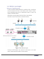

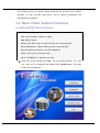
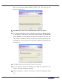
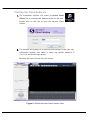
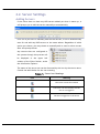
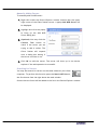
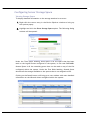
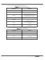
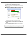
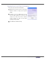
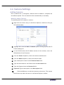
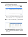
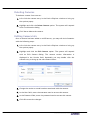
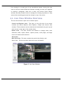
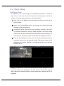

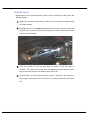
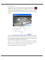
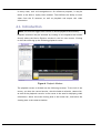
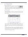
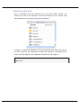
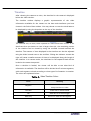
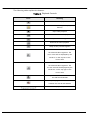
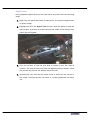
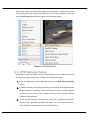
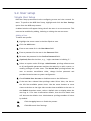
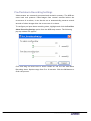
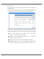

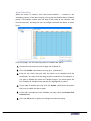
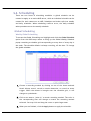
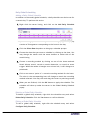
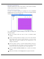
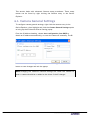
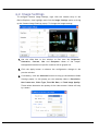
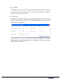
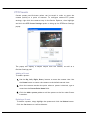
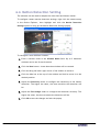

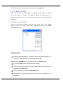
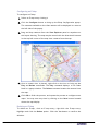


![[Product Name]](http://vs1.manualzilla.com/store/data/005815260_1-ef599fe6f64155e467bbb545a8fc0a5d-150x150.png)