1
CF.book Page 1 Friday, July 8, 2005 8:59 AM
CodeWarrior™
Development Studio for
ColdFire®
Architectures v6.0
Targeting Manual
Revised: 30 June 2005
CF.book Page 2 Friday, July 8, 2005 8:59 AM
Freescale and the Freescale logo are trademarks of Frrescale Semiconductor, Inc. Metrowerks, the Metrowerks logo,
and CodeWarrior are trademarks or registered trademarks of Metrowerks Corporation in the United States and/or other
countries. All other trade names and trademarks are the property of their respective owners.
Copyright © 2003-2005 by Metrowerks, a Freescale Semiconductor company. All rights reserved.
No portion of this document may be reproduced or transmitted in any form or by any means, electronic or mechanical, without prior written permission from Metrowerks. Use of this document and related materials is governed by the license agreement that accompanied the product to which this manual pertains. This document may
be printed for non-commercial personal use only in accordance with the aforementioned license agreement. If
you do not have a copy of the license agreement, contact your Metrowerks representative or call 1-800-377-5416
(if outside the U.S., call +1-512-996-5300).
Metrowerks reserves the right to make changes to any product described or referred to in this document without further
notice. Metrowerks makes no warranty, representation or guarantee regarding the merchantability or fitness of its products for any particular purpose, nor does Metrowerks assume any liability arising out of the application or use of any
product described herein and specifically disclaims any and all liability. Metrowerks software is not authorized for
and has not been designed, tested, manufactured, or intended for use in developing applications where the failure, malfunction, or any inaccuracy of the application carries a risk of death, serious bodily injury, or damage
to tangible property, including, but not limited to, use in factory control systems, medical devices or facilities,
nuclear facilities, aircraft navigation or communication, emergency systems, or other applications with a similar
degree of potential hazard.
How to Contact Metrowerks
Corporate Headquarters
Metrowerks Corporation
7700 West Parmer Lane
Austin, TX 78729
U.S.A.
World Wide Web
http://www.freescale.com/codewarrior
Technical Support
http://www.freescale.com/support
CF.book Page 3 Friday, July 8, 2005 8:59 AM
Table of Contents
1
Introduction
11
Read the Developer Notes. . . . . . . . . . . . . . . . . . . . . . . . . . . . . . . . . . . . . . . . . . 11
Features . . . . . . . . . . . . . . . . . . . . . . . . . . . . . . . . . . . . . . . . . . . . . . . . . . . . . . . . 11
CodeWarrior Editions . . . . . . . . . . . . . . . . . . . . . . . . . . . . . . . . . . . . . . . . . . . . . 12
About this Manual . . . . . . . . . . . . . . . . . . . . . . . . . . . . . . . . . . . . . . . . . . . . . . . 13
Documentation Overview . . . . . . . . . . . . . . . . . . . . . . . . . . . . . . . . . . . . . . . . . . 14
Additional Information Resources . . . . . . . . . . . . . . . . . . . . . . . . . . . . . . . . . . . 15
2
Getting Started
17
System Requirements . . . . . . . . . . . . . . . . . . . . . . . . . . . . . . . . . . . . . . . . . . . . . 17
Host Requirements . . . . . . . . . . . . . . . . . . . . . . . . . . . . . . . . . . . . . . . . . . . . 17
Target Board Requirements. . . . . . . . . . . . . . . . . . . . . . . . . . . . . . . . . . . . . . 17
CodeWarrior IDE . . . . . . . . . . . . . . . . . . . . . . . . . . . . . . . . . . . . . . . . . . . . . . . . 18
CodeWarrior Development Process . . . . . . . . . . . . . . . . . . . . . . . . . . . . . . . . . . 19
Project Files. . . . . . . . . . . . . . . . . . . . . . . . . . . . . . . . . . . . . . . . . . . . . . . . . . 21
Editing Code . . . . . . . . . . . . . . . . . . . . . . . . . . . . . . . . . . . . . . . . . . . . . . . . . 22
Building: Compiling and Linking . . . . . . . . . . . . . . . . . . . . . . . . . . . . . . . . . 22
Debugging . . . . . . . . . . . . . . . . . . . . . . . . . . . . . . . . . . . . . . . . . . . . . . . . . . . 23
Disassembling . . . . . . . . . . . . . . . . . . . . . . . . . . . . . . . . . . . . . . . . . . . . . . . . 23
3
Application Tutorial
25
Create a Project . . . . . . . . . . . . . . . . . . . . . . . . . . . . . . . . . . . . . . . . . . . . . . . . . . 25
Build the Project . . . . . . . . . . . . . . . . . . . . . . . . . . . . . . . . . . . . . . . . . . . . . . . . . 30
Debug the Application . . . . . . . . . . . . . . . . . . . . . . . . . . . . . . . . . . . . . . . . . . . . 32
4
Target Settings
39
Target Settings Overview . . . . . . . . . . . . . . . . . . . . . . . . . . . . . . . . . . . . . . . . . . 39
ColdFire Settings Panels . . . . . . . . . . . . . . . . . . . . . . . . . . . . . . . . . . . . . . . . . . . 40
Target Settings. . . . . . . . . . . . . . . . . . . . . . . . . . . . . . . . . . . . . . . . . . . . . . . . 41
BatchRunner PreLinker. . . . . . . . . . . . . . . . . . . . . . . . . . . . . . . . . . . . . . . . . 43
BatchRunner PostLinker . . . . . . . . . . . . . . . . . . . . . . . . . . . . . . . . . . . . . . . . 43
ColdFire Target . . . . . . . . . . . . . . . . . . . . . . . . . . . . . . . . . . . . . . . . . . . . . . . 44
ColdFire Architectures v6.0 - Targeting Manual
3
CF.book Page 4 Friday, July 8, 2005 8:59 AM
Table of Contents
ColdFire Assembler . . . . . . . . . . . . . . . . . . . . . . . . . . . . . . . . . . . . . . . . . . . .44
ELF Disassembler . . . . . . . . . . . . . . . . . . . . . . . . . . . . . . . . . . . . . . . . . . . . .47
ColdFire Processor . . . . . . . . . . . . . . . . . . . . . . . . . . . . . . . . . . . . . . . . . . . .51
ColdFire Linker . . . . . . . . . . . . . . . . . . . . . . . . . . . . . . . . . . . . . . . . . . . . . . .55
Debugger PIC Settings . . . . . . . . . . . . . . . . . . . . . . . . . . . . . . . . . . . . . . . . .59
5
Compilers
61
Language Extensions. . . . . . . . . . . . . . . . . . . . . . . . . . . . . . . . . . . . . . . . . . . . . .62
PC-Relative Strings . . . . . . . . . . . . . . . . . . . . . . . . . . . . . . . . . . . . . . . . . . . .62
Declaration Specifiers . . . . . . . . . . . . . . . . . . . . . . . . . . . . . . . . . . . . . . . . . .63
Integer Formats . . . . . . . . . . . . . . . . . . . . . . . . . . . . . . . . . . . . . . . . . . . . . . . . . .64
Calling Conventions . . . . . . . . . . . . . . . . . . . . . . . . . . . . . . . . . . . . . . . . . . . . . .65
Variable Allocation . . . . . . . . . . . . . . . . . . . . . . . . . . . . . . . . . . . . . . . . . . . . . . .66
Register Variables . . . . . . . . . . . . . . . . . . . . . . . . . . . . . . . . . . . . . . . . . . . . . . . .67
Pragmas . . . . . . . . . . . . . . . . . . . . . . . . . . . . . . . . . . . . . . . . . . . . . . . . . . . . . . . .67
codeColdFire . . . . . . . . . . . . . . . . . . . . . . . . . . . . . . . . . . . . . . . . . . . . . . . . .69
const_multiply . . . . . . . . . . . . . . . . . . . . . . . . . . . . . . . . . . . . . . . . . . . . . . . .69
define_section . . . . . . . . . . . . . . . . . . . . . . . . . . . . . . . . . . . . . . . . . . . . . . . .69
emac. . . . . . . . . . . . . . . . . . . . . . . . . . . . . . . . . . . . . . . . . . . . . . . . . . . . . . . .71
explicit_zero_data . . . . . . . . . . . . . . . . . . . . . . . . . . . . . . . . . . . . . . . . . . . . .72
inline_intrinsics . . . . . . . . . . . . . . . . . . . . . . . . . . . . . . . . . . . . . . . . . . . . . . .72
interrupt . . . . . . . . . . . . . . . . . . . . . . . . . . . . . . . . . . . . . . . . . . . . . . . . . . . . .73
opt_unroll_count . . . . . . . . . . . . . . . . . . . . . . . . . . . . . . . . . . . . . . . . . . . . . .73
opt_unroll_instr_count. . . . . . . . . . . . . . . . . . . . . . . . . . . . . . . . . . . . . . . . . .73
profile. . . . . . . . . . . . . . . . . . . . . . . . . . . . . . . . . . . . . . . . . . . . . . . . . . . . . . .74
readonly_strings. . . . . . . . . . . . . . . . . . . . . . . . . . . . . . . . . . . . . . . . . . . . . . .74
SDS_debug_support . . . . . . . . . . . . . . . . . . . . . . . . . . . . . . . . . . . . . . . . . . .74
section . . . . . . . . . . . . . . . . . . . . . . . . . . . . . . . . . . . . . . . . . . . . . . . . . . . . . .74
Predefined Symbols. . . . . . . . . . . . . . . . . . . . . . . . . . . . . . . . . . . . . . . . . . . . . . .75
Position-Independent Code . . . . . . . . . . . . . . . . . . . . . . . . . . . . . . . . . . . . . . . . .76
6
ELF Linker and Command Language
77
LCF Structure . . . . . . . . . . . . . . . . . . . . . . . . . . . . . . . . . . . . . . . . . . . . . . . . . . .77
Memory Segment. . . . . . . . . . . . . . . . . . . . . . . . . . . . . . . . . . . . . . . . . . . . . .77
Closure Segments . . . . . . . . . . . . . . . . . . . . . . . . . . . . . . . . . . . . . . . . . . . . .78
4
ColdFire Architectures v6.0 - Targeting Manual
CF.book Page 5 Friday, July 8, 2005 8:59 AM
Table of Contents
Sections Segment . . . . . . . . . . . . . . . . . . . . . . . . . . . . . . . . . . . . . . . . . . . . . 79
LCF Syntax . . . . . . . . . . . . . . . . . . . . . . . . . . . . . . . . . . . . . . . . . . . . . . . . . . . . . 80
Variables, Expressions, and Integrals . . . . . . . . . . . . . . . . . . . . . . . . . . . . . . 80
Arithmetic, Comment Operators . . . . . . . . . . . . . . . . . . . . . . . . . . . . . . . . . . 81
Alignment . . . . . . . . . . . . . . . . . . . . . . . . . . . . . . . . . . . . . . . . . . . . . . . . . . . 82
Specifying Files and Functions . . . . . . . . . . . . . . . . . . . . . . . . . . . . . . . . . . . 83
Stack and Heap . . . . . . . . . . . . . . . . . . . . . . . . . . . . . . . . . . . . . . . . . . . . . . . 84
Static Initializers . . . . . . . . . . . . . . . . . . . . . . . . . . . . . . . . . . . . . . . . . . . . . . 85
Exception Tables . . . . . . . . . . . . . . . . . . . . . . . . . . . . . . . . . . . . . . . . . . . . . . 85
Position-Independent Code and Data . . . . . . . . . . . . . . . . . . . . . . . . . . . . . . 85
ROM-RAM Copying. . . . . . . . . . . . . . . . . . . . . . . . . . . . . . . . . . . . . . . . . . . 86
Writing Data Directly to Memory. . . . . . . . . . . . . . . . . . . . . . . . . . . . . . . . . 88
Commands, Directives, and Keywords . . . . . . . . . . . . . . . . . . . . . . . . . . . . . . . . 89
. (location counter) . . . . . . . . . . . . . . . . . . . . . . . . . . . . . . . . . . . . . . . . . . . . 90
ADDR . . . . . . . . . . . . . . . . . . . . . . . . . . . . . . . . . . . . . . . . . . . . . . . . . . . . . . 90
ALIGN . . . . . . . . . . . . . . . . . . . . . . . . . . . . . . . . . . . . . . . . . . . . . . . . . . . . . 91
ALIGNALL. . . . . . . . . . . . . . . . . . . . . . . . . . . . . . . . . . . . . . . . . . . . . . . . . . 92
EXCEPTION. . . . . . . . . . . . . . . . . . . . . . . . . . . . . . . . . . . . . . . . . . . . . . . . . 92
EXPORTSTRTAB. . . . . . . . . . . . . . . . . . . . . . . . . . . . . . . . . . . . . . . . . . . . . 93
EXPORTSYMTAB . . . . . . . . . . . . . . . . . . . . . . . . . . . . . . . . . . . . . . . . . . . . 94
FORCE_ACTIVE . . . . . . . . . . . . . . . . . . . . . . . . . . . . . . . . . . . . . . . . . . . . . 95
IMPORTSTRTAB . . . . . . . . . . . . . . . . . . . . . . . . . . . . . . . . . . . . . . . . . . . . . 95
IMPORTSYMTAB . . . . . . . . . . . . . . . . . . . . . . . . . . . . . . . . . . . . . . . . . . . . 96
INCLUDE . . . . . . . . . . . . . . . . . . . . . . . . . . . . . . . . . . . . . . . . . . . . . . . . . . . 97
KEEP_SECTION . . . . . . . . . . . . . . . . . . . . . . . . . . . . . . . . . . . . . . . . . . . . . 97
MEMORY . . . . . . . . . . . . . . . . . . . . . . . . . . . . . . . . . . . . . . . . . . . . . . . . . . . 97
OBJECT . . . . . . . . . . . . . . . . . . . . . . . . . . . . . . . . . . . . . . . . . . . . . . . . . . . . 99
REF_INCLUDE . . . . . . . . . . . . . . . . . . . . . . . . . . . . . . . . . . . . . . . . . . . . . . 99
SECTIONS . . . . . . . . . . . . . . . . . . . . . . . . . . . . . . . . . . . . . . . . . . . . . . . . . 100
SIZEOF . . . . . . . . . . . . . . . . . . . . . . . . . . . . . . . . . . . . . . . . . . . . . . . . . . . . 101
SIZEOF_ROM . . . . . . . . . . . . . . . . . . . . . . . . . . . . . . . . . . . . . . . . . . . . . . 101
WRITEB . . . . . . . . . . . . . . . . . . . . . . . . . . . . . . . . . . . . . . . . . . . . . . . . . . . 102
WRITEH . . . . . . . . . . . . . . . . . . . . . . . . . . . . . . . . . . . . . . . . . . . . . . . . . . . 102
WRITEW . . . . . . . . . . . . . . . . . . . . . . . . . . . . . . . . . . . . . . . . . . . . . . . . . . 102
WRITES0COMMENT . . . . . . . . . . . . . . . . . . . . . . . . . . . . . . . . . . . . . . . . 103
ColdFire Architectures v6.0 - Targeting Manual
5
CF.book Page 6 Friday, July 8, 2005 8:59 AM
Table of Contents
ZERO_FILL_UNINITIALIZED . . . . . . . . . . . . . . . . . . . . . . . . . . . . . . . . .103
7
ColdFire Linker Notes
105
Program Sections. . . . . . . . . . . . . . . . . . . . . . . . . . . . . . . . . . . . . . . . . . . . . . . .105
Deadstripping . . . . . . . . . . . . . . . . . . . . . . . . . . . . . . . . . . . . . . . . . . . . . . . . . .106
Link Order . . . . . . . . . . . . . . . . . . . . . . . . . . . . . . . . . . . . . . . . . . . . . . . . . . . . .107
Executable files in Projects . . . . . . . . . . . . . . . . . . . . . . . . . . . . . . . . . . . . . . . .107
S-Record Comments . . . . . . . . . . . . . . . . . . . . . . . . . . . . . . . . . . . . . . . . . . . . .107
8
Inline Assembly
109
Inline Assembly Syntax . . . . . . . . . . . . . . . . . . . . . . . . . . . . . . . . . . . . . . . . . .109
Statements . . . . . . . . . . . . . . . . . . . . . . . . . . . . . . . . . . . . . . . . . . . . . . . . . .109
Additional Syntax Rules . . . . . . . . . . . . . . . . . . . . . . . . . . . . . . . . . . . . . . .111
Preprocessor Features . . . . . . . . . . . . . . . . . . . . . . . . . . . . . . . . . . . . . . . . .111
Local Variables and Arguments. . . . . . . . . . . . . . . . . . . . . . . . . . . . . . . . . .111
Returning From a Routine . . . . . . . . . . . . . . . . . . . . . . . . . . . . . . . . . . . . . .113
Inline Assembly Directives . . . . . . . . . . . . . . . . . . . . . . . . . . . . . . . . . . . . . . . .113
dc . . . . . . . . . . . . . . . . . . . . . . . . . . . . . . . . . . . . . . . . . . . . . . . . . . . . . . . . .114
ds . . . . . . . . . . . . . . . . . . . . . . . . . . . . . . . . . . . . . . . . . . . . . . . . . . . . . . . . .114
entry . . . . . . . . . . . . . . . . . . . . . . . . . . . . . . . . . . . . . . . . . . . . . . . . . . . . . . .115
fralloc. . . . . . . . . . . . . . . . . . . . . . . . . . . . . . . . . . . . . . . . . . . . . . . . . . . . . .116
frfree . . . . . . . . . . . . . . . . . . . . . . . . . . . . . . . . . . . . . . . . . . . . . . . . . . . . . .116
machine . . . . . . . . . . . . . . . . . . . . . . . . . . . . . . . . . . . . . . . . . . . . . . . . . . . .117
naked . . . . . . . . . . . . . . . . . . . . . . . . . . . . . . . . . . . . . . . . . . . . . . . . . . . . . .117
opword . . . . . . . . . . . . . . . . . . . . . . . . . . . . . . . . . . . . . . . . . . . . . . . . . . . . .118
return . . . . . . . . . . . . . . . . . . . . . . . . . . . . . . . . . . . . . . . . . . . . . . . . . . . . . .118
9
Debugging
119
Target Settings for Debugging. . . . . . . . . . . . . . . . . . . . . . . . . . . . . . . . . . . . . .119
CF Debugger Settings Panel . . . . . . . . . . . . . . . . . . . . . . . . . . . . . . . . . . . .121
Remote Debugging Panel . . . . . . . . . . . . . . . . . . . . . . . . . . . . . . . . . . . . . .124
CF Exceptions Panel . . . . . . . . . . . . . . . . . . . . . . . . . . . . . . . . . . . . . . . . . .128
Debugger Settings Panel . . . . . . . . . . . . . . . . . . . . . . . . . . . . . . . . . . . . . . .131
CF Interrupt Panel . . . . . . . . . . . . . . . . . . . . . . . . . . . . . . . . . . . . . . . . . . . .133
Remote Connections for Debugging . . . . . . . . . . . . . . . . . . . . . . . . . . . . . . . . .134
6
ColdFire Architectures v6.0 - Targeting Manual
CF.book Page 7 Friday, July 8, 2005 8:59 AM
Table of Contents
Abatron Remote Connections . . . . . . . . . . . . . . . . . . . . . . . . . . . . . . . . . . . 134
P&E Microsystems Remote Connections . . . . . . . . . . . . . . . . . . . . . . . . . . 136
ISS Remote Connection . . . . . . . . . . . . . . . . . . . . . . . . . . . . . . . . . . . . . . . 139
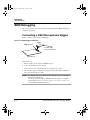
BDM Debugging. . . . . . . . . . . . . . . . . . . . . . . . . . . . . . . . . . . . . . . . . . . . . . . . 142
Connecting a P&E Microsystems Wiggler . . . . . . . . . . . . . . . . . . . . . . . . . 142
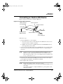
Connecting an Abatron BDI Device . . . . . . . . . . . . . . . . . . . . . . . . . . . . . . 143
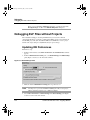
Debugging ELF Files without Projects. . . . . . . . . . . . . . . . . . . . . . . . . . . . . . . 144
Updating IDE Preferences. . . . . . . . . . . . . . . . . . . . . . . . . . . . . . . . . . . . . . 144
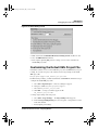
Customizing the Default XML Project File . . . . . . . . . . . . . . . . . . . . . . . . 145
Debugging an ELF File . . . . . . . . . . . . . . . . . . . . . . . . . . . . . . . . . . . . . . . . 146
Additional ELF-Debugging Considerations . . . . . . . . . . . . . . . . . . . . . . . . 147
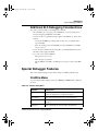
Special Debugger Features . . . . . . . . . . . . . . . . . . . . . . . . . . . . . . . . . . . . . . . . 147
ColdFire Menu . . . . . . . . . . . . . . . . . . . . . . . . . . . . . . . . . . . . . . . . . . . . . . 147
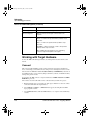
Working with Target Hardware . . . . . . . . . . . . . . . . . . . . . . . . . . . . . . . . . . 148
Using the Simple Profiler . . . . . . . . . . . . . . . . . . . . . . . . . . . . . . . . . . . . . . 149
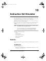
10 Instruction Set Simulator
151
Features . . . . . . . . . . . . . . . . . . . . . . . . . . . . . . . . . . . . . . . . . . . . . . . . . . . . . . . 151
ColdFire V2. . . . . . . . . . . . . . . . . . . . . . . . . . . . . . . . . . . . . . . . . . . . . . . . . 151
ColdFire V4e . . . . . . . . . . . . . . . . . . . . . . . . . . . . . . . . . . . . . . . . . . . . . . . . 152
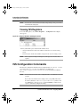
Using the Simulator . . . . . . . . . . . . . . . . . . . . . . . . . . . . . . . . . . . . . . . . . . . . . 153
Console Window . . . . . . . . . . . . . . . . . . . . . . . . . . . . . . . . . . . . . . . . . . . . . 153
Viewing ISS Registers. . . . . . . . . . . . . . . . . . . . . . . . . . . . . . . . . . . . . . . . . 154
ISS Configuration Commands . . . . . . . . . . . . . . . . . . . . . . . . . . . . . . . . . . . . . 154
bus_dump . . . . . . . . . . . . . . . . . . . . . . . . . . . . . . . . . . . . . . . . . . . . . . . . . . 155
cache_size . . . . . . . . . . . . . . . . . . . . . . . . . . . . . . . . . . . . . . . . . . . . . . . . . . 156
ipsbar . . . . . . . . . . . . . . . . . . . . . . . . . . . . . . . . . . . . . . . . . . . . . . . . . . . . . . 156
kram_size . . . . . . . . . . . . . . . . . . . . . . . . . . . . . . . . . . . . . . . . . . . . . . . . . . 157
krom_size . . . . . . . . . . . . . . . . . . . . . . . . . . . . . . . . . . . . . . . . . . . . . . . . . . 157
krom_valid. . . . . . . . . . . . . . . . . . . . . . . . . . . . . . . . . . . . . . . . . . . . . . . . . . 158
mbar. . . . . . . . . . . . . . . . . . . . . . . . . . . . . . . . . . . . . . . . . . . . . . . . . . . . . . . 158
mbus_multiplier . . . . . . . . . . . . . . . . . . . . . . . . . . . . . . . . . . . . . . . . . . . . . 159
memory . . . . . . . . . . . . . . . . . . . . . . . . . . . . . . . . . . . . . . . . . . . . . . . . . . . . 159
sdram . . . . . . . . . . . . . . . . . . . . . . . . . . . . . . . . . . . . . . . . . . . . . . . . . . . . . . 160
Sample Configuration File . . . . . . . . . . . . . . . . . . . . . . . . . . . . . . . . . . . . . . . . 160
ColdFire Architectures v6.0 - Targeting Manual
7
CF.book Page 8 Friday, July 8, 2005 8:59 AM
Table of Contents
ISS Limitations . . . . . . . . . . . . . . . . . . . . . . . . . . . . . . . . . . . . . . . . . . . . . . . . .161
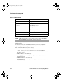
11 Libraries and Runtime Code
163
MSL for ColdFire Development . . . . . . . . . . . . . . . . . . . . . . . . . . . . . . . . . . . .163
Using MSL for ColdFire . . . . . . . . . . . . . . . . . . . . . . . . . . . . . . . . . . . . . . .163
Additional Aspects . . . . . . . . . . . . . . . . . . . . . . . . . . . . . . . . . . . . . . . . . . .165
Runtime Libraries . . . . . . . . . . . . . . . . . . . . . . . . . . . . . . . . . . . . . . . . . . . . . . .167
Position-Independent Code . . . . . . . . . . . . . . . . . . . . . . . . . . . . . . . . . . . . .168
Board Initialization Code. . . . . . . . . . . . . . . . . . . . . . . . . . . . . . . . . . . . . . .168
12 Using Hardware Tools
169
Flash Programmer . . . . . . . . . . . . . . . . . . . . . . . . . . . . . . . . . . . . . . . . . . . . . . .169
Hardware Diagnostics . . . . . . . . . . . . . . . . . . . . . . . . . . . . . . . . . . . . . . . . . . . .174
13 Command-Line Tools
179
Command-Line Executables . . . . . . . . . . . . . . . . . . . . . . . . . . . . . . . . . . . . . . .179
Environment Variables . . . . . . . . . . . . . . . . . . . . . . . . . . . . . . . . . . . . . . . . . . .179
Compiling and Linking . . . . . . . . . . . . . . . . . . . . . . . . . . . . . . . . . . . . . . . . . . .181
Assembler Options . . . . . . . . . . . . . . . . . . . . . . . . . . . . . . . . . . . . . . . . . . .183
Compiler Options . . . . . . . . . . . . . . . . . . . . . . . . . . . . . . . . . . . . . . . . . . . .184
Linker Options . . . . . . . . . . . . . . . . . . . . . . . . . . . . . . . . . . . . . . . . . . . . . .194
A Using Debug Initialization Files
203
Common File Uses . . . . . . . . . . . . . . . . . . . . . . . . . . . . . . . . . . . . . . . . . . . . . .203
Command Syntax . . . . . . . . . . . . . . . . . . . . . . . . . . . . . . . . . . . . . . . . . . . . . . .205
Command Reference . . . . . . . . . . . . . . . . . . . . . . . . . . . . . . . . . . . . . . . . . . . . .206
Delay . . . . . . . . . . . . . . . . . . . . . . . . . . . . . . . . . . . . . . . . . . . . . . . . . . . . . .206
ResetHalt . . . . . . . . . . . . . . . . . . . . . . . . . . . . . . . . . . . . . . . . . . . . . . . . . . .207
ResetRun . . . . . . . . . . . . . . . . . . . . . . . . . . . . . . . . . . . . . . . . . . . . . . . . . . .207
Stop . . . . . . . . . . . . . . . . . . . . . . . . . . . . . . . . . . . . . . . . . . . . . . . . . . . . . . .207
writeaddressreg . . . . . . . . . . . . . . . . . . . . . . . . . . . . . . . . . . . . . . . . . . . . . .207
writecontrolreg. . . . . . . . . . . . . . . . . . . . . . . . . . . . . . . . . . . . . . . . . . . . . . .208
writedatareg . . . . . . . . . . . . . . . . . . . . . . . . . . . . . . . . . . . . . . . . . . . . . . . . .208
writemem.b . . . . . . . . . . . . . . . . . . . . . . . . . . . . . . . . . . . . . . . . . . . . . . . . .209
writemem.l . . . . . . . . . . . . . . . . . . . . . . . . . . . . . . . . . . . . . . . . . . . . . . . . . .209
8
ColdFire Architectures v6.0 - Targeting Manual
CF.book Page 9 Friday, July 8, 2005 8:59 AM
Table of Contents
writemem.w. . . . . . . . . . . . . . . . . . . . . . . . . . . . . . . . . . . . . . . . . . . . . . . . . 210
B Memory Configuration Files
211
Command Syntax . . . . . . . . . . . . . . . . . . . . . . . . . . . . . . . . . . . . . . . . . . . . . . . 211
Command Explanations . . . . . . . . . . . . . . . . . . . . . . . . . . . . . . . . . . . . . . . . . . 212
range . . . . . . . . . . . . . . . . . . . . . . . . . . . . . . . . . . . . . . . . . . . . . . . . . . . . . . 212
reserved . . . . . . . . . . . . . . . . . . . . . . . . . . . . . . . . . . . . . . . . . . . . . . . . . . . . 213
reservedchar . . . . . . . . . . . . . . . . . . . . . . . . . . . . . . . . . . . . . . . . . . . . . . . . 213
Index
ColdFire Architectures v6.0 - Targeting Manual
215
9
CF.book Page 10 Friday, July 8, 2005 8:59 AM
Table of Contents
10
ColdFire Architectures v6.0 - Targeting Manual
CF.book Page 11 Friday, July 8, 2005 8:59 AM
1
Introduction
This manual explains how to use CodeWarrior™ development tools to develop
applications for the Freescale™ ColdFire® family of integrated microprocessors.
This chapter consists of these sections:
• Read the Developer Notes
• Features
• CodeWarrior Editions
• About this Manual
• Documentation Overview
• Additional Information Resources
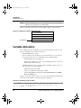
Read the Developer Notes
Before using the CodeWarrior IDE, read the developer notes. These notes contain
important information about last-minute changes, bug fixes, incompatible elements, or
other topics that may not be included in this manual.
NOTE
The release notes for specific components of the CodeWarrior IDE are located
at location: {CodeWarrior_Dir}\Release_Notes, where
{CodeWarrior_Dir} is the CodeWarrior installation directory.
If you are new to the CodeWarrior IDE, read this chapter and the Getting Started chapter.
This chapter provides references to resources of interest to new users; the Getting Started
chapter helps you become familiar with the software features.
Features
The CodeWarrior Development Studio for ColdFire Architectures includes these features:
• Latest version of the CodeWarrior IDE, which the IDE User’s Guide explains.
• Support for the latest ColdFire processors: CFM5213, and variants CFM5211 and
CFM5212.
ColdFire Architectures v6.0 - Targeting Manual
11
CF.book Page 12 Friday, July 8, 2005 8:59 AM
Introduction
CodeWarrior Editions
• Support for previous processors of the ColdFire family, such as CFM547x/548x,
CFM5307, CFM523x, CFM5282, CFM5275, and CFM5249. For more information,
see ColdFire Processor
• Flash-programmer and hardware-diagnostics support. For more information, see
Using Hardware Tools.
• USB debugging support through the P&E Micro protocol. For more information, see
P&E Microsystems Remote Connections.
• Instruction Set Simulator (ISS) for V2 and V4e processor cores. For more
information, see Remote Connections for Debugging and Instruction Set Simulator
• For previous processors of the ColdFire family, support for the simple profiler. For
more information, see Using the Simple Profiler and the Profiler User’s Guide. (This
profiler support is not available for CFM5213, CFM5211, or CFM5212 processors.)
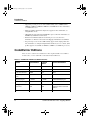
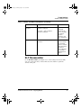
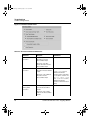
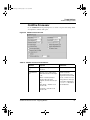
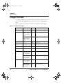
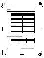
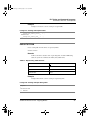
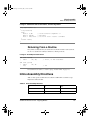
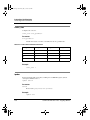
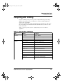
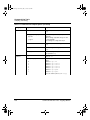
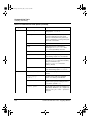
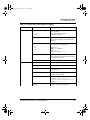
CodeWarrior Editions
There are three editions of CodeWarrior™ Development Studio for ColdFire ®
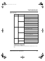
Architectures, version 6.0. Table 1.1 shows their feature differences.
Table 1.1 CodeWarrior ColdFire 6.0 Edition Features
Feature
Special Edition
Standard
Edition
Professional Edition
IDE
Yes
Yes
Yes
Compiles source code
ASM and C
ASM and C
ASM, C, and C++
Code size restrictions
128KB
None
None
Compiler optimization
levels
Unlimited
Unlimited
Unlimited
3rd-party plug-ins
No RTOS
No RTOS
Unlimited RTOS plug-ins
CodeWarrior Debugger
Yes
Yes
Yes
Debugger hardware
connections
P&E Parallel and
USB
P&E Parallel and
USB
P&E Parallel, USB, and
Lightning; Abatron serial and
TCP/IP
V2, V4e simulator
No
Yes
Yes
12
ColdFire Architectures v6.0 - Targeting Manual
CF.book Page 13 Friday, July 8, 2005 8:59 AM
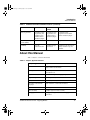
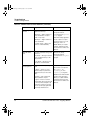
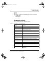
Introduction
About this Manual
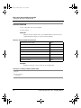
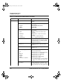
Table 1.1 CodeWarrior ColdFire 6.0 Edition Features (continued)
Feature
Special Edition
Standard
Edition
Professional Edition
Flash programmers
CodeWarrior Flash
Programmer (129
megabytes) and
ColdFire Flasher
standalone plug-in
CodeWarrior Flash
Programmer and
ColdFire Flasher
standalone plug-in
CodeWarrior Flash
Programmer and ColdFire
Flasher standalone plug-in
Real time operating
system (RTOS)
Not available
Not available
Plug-ins available
Availability
Free with
evaluation board
Available through
all channels
Available through all channels.
30-day evaluation copy also
available.
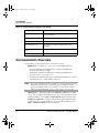
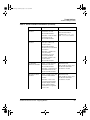
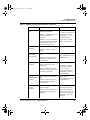
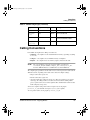
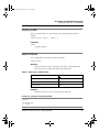
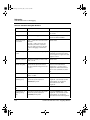
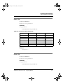
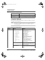
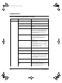
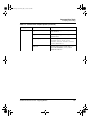
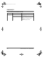
About this Manual
Table 1.2 lists the contents of this manual.
Table 1.2 Chapter, Appendix Contents
Chapter/Appendix
Explains
Introduction
New features; contents of this manual; technical
support; further documentation
Getting Started
System requirements; overview of CodeWarrior
development tools
Application Tutorial
Tutorial for writing and debugging programs
Target Settings
Controlling the compiler and linker
Compilers
ColdFire-specific compiler informationColdFire
ELF Linker and Command
Language
Linker and linker command file information
ColdFire Linker Notes
Linker capabilities
Inline Assembly
Compiler support for inline assembly
Debugging
Debugger settings panels; remote debugging
connections
ColdFire Architectures v6.0 - Targeting Manual
13
CF.book Page 14 Friday, July 8, 2005 8:59 AM
Introduction
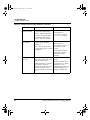
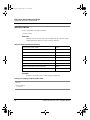
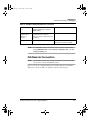
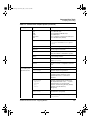
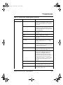
Documentation Overview
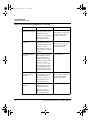
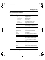
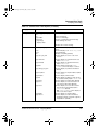
Table 1.2 Chapter, Appendix Contents (continued)
Chapter/Appendix
Explains
Instruction Set Simulator
Instruction Set Simulator, including configuration for
your requirements.
Libraries and Runtime Code
Libraries for ColdFire targets
Using Hardware Tools
Flash programmer and hardware diagnostics tools
Command-Line Tools
Command-line compiler, assembler, linker, and
debugger
Using Debug Initialization
Files
Debug initialization files
Memory Configuration Files
Defining access for areas of memory
Documentation Overview
Documentation for your CodeWarrior tools comes in three formats:
• PDF manuals — in subdirectory \Help\PDF of your installation directory.
– The Target Settings and Debugging chapters of this Targeting Manual are
extensions of the IDE User’s Guide.
– The Compilers and Inline Assembly chapters of this Targeting Manual are
extensions of the C Compilers Reference.
– The Libraries and Runtime Code chapter of this Targeting Manual is an extension
of the MSL C Reference and the MSL C++ Reference.
NOTE
For complete information about a particular topic, you may need to look in this
Targeting manual and in the corresponding generic CodeWarrior manual.
To view any PDF document, you need Adobe® Acrobat® Reader software,
which you can download from: http://www.adobe.com/acrobat
• CHM help files — information in Microsoft® HTML Help CHM format, in folder
\Help of the CodeWarrior installation directory. To view this information, start the
CodeWarrior IDE, then select Help > Online Manuals from the main menu bar.
• CodeWarrior online help — information about using the IDE and understanding
error messages. To access this information, start the CodeWarrior IDE, then select
Help > CodeWarrior Help from the main menu bar.
14
ColdFire Architectures v6.0 - Targeting Manual
CF.book Page 15 Friday, July 8, 2005 8:59 AM
Introduction
Additional Information Resources
Additional Information Resources
• For general information about the CodeWarrior IDE and debugger, see the IDE
User’s Guide.
• For information specific to the C/C++ front-end compiler, see the C Compilers
Reference.
• For information about Metrowerks standard C/C++ libraries, see the MSL C
Reference and the MSL C++ Reference.
• For instructions on programming in C, C++, Java, and Pascal — all in one
environment, see the Discover Programming edition of CodeWarrior software.
• For PDF-format documentation about Freescale processors and cores, go to the
\Freescale_Documentation subdirectory of your CodeWarrior installation
directory.
• For Freescale documentation and resources, visit the Freescale, Inc. web site:
http://www.freescale.com
• For additional electronic-design and embedded-system resources, visit the EG3
Communications, Inc. web site: http://www.eg3.com
• For monthly and weekly forum information about programming embedded systems
(including source-code examples), visit the Embedded Systems Programming
magazine web site: http://www.embedded.com
ColdFire Architectures v6.0 - Targeting Manual
15
CF.book Page 16 Friday, July 8, 2005 8:59 AM
Introduction
Additional Information Resources
16
ColdFire Architectures v6.0 - Targeting Manual
CF.book Page 17 Friday, July 8, 2005 8:59 AM
2
Getting Started
This chapter helps you install the CodeWarrior™ Development Studio for ColdFire
Architectures. It also gives an overview of the CodeWarrior environment and tools.
This chapter consists of these sections:
• System Requirements
• CodeWarrior IDE
• CodeWarrior Development Process
System Requirements
Your host computer system and your target board must meet minimum requirements.
Host Requirements
Your computer (PC) needs:
• 800 MHz Pentium®-compatible microprocessor
• Windows® 2000 or XP operating system
• 512 megabytes of RAM
• CD-ROM drive
• 350 megabytes free memory space, plus space for projects and source code
• Serial port (or Ethernet connector), to connect your PC to the embedded target — for
debugging with an Abatron BDI device
• Parallel port (or P&E Lightning board) — to use a wiggler to connect to BDM/JTAG
targets
• USB port — P&E Micro to use a USB device through the P&E Micro Protocol.
Target Board Requirements
Your functional embedded system needs:
• ColdFire evaluation board, with a processor such as CFM5213, CFM5282,
CFM5407, CFM5235, CFM5271, CFM5307, or CFM5485
ColdFire Architectures v6.0 - Targeting Manual
17
CF.book Page 18 Friday, July 8, 2005 8:59 AM
Getting Started
CodeWarrior IDE
• Serial or null-modem cables to connect the host computer and target board; your
target board determines the specific cables you need.
• For a BDM/JTAG connection, parallel cables to connect the computer to a wiggler.
• Appropriate power supply for the target board.
CodeWarrior IDE
The CodeWarrior IDE consists of a project manager, a graphical user interface, compilers,
linkers, a debugger, a source-code browser, and editing tools. You can edit, navigate,
examine, compile, link, and debug code, within the one CodeWarrior environment. The
CodeWarrior IDE lets you configure options for code generation, debugging, and
navigation of your project.
Unlike command-line development tools, the CodeWarrior IDE organizes all files related
to your project. You can see your project at a glance, so organization of your source code
files is easy. Navigation among those files is easy, too.
When you use the CodeWarrior IDE, there is no need for complicated build scripts or
makefiles. To add or delete source code files from a project, you use your mouse and
keyboard, instead of tediously editing a build script.
For any project, you can create and manage several configurations for use on different
computer platforms. The platform on which you run the CodeWarrior IDE is called the
host. From the host, you can use the CodeWarrior IDE to develop code to target various
platforms.
Note the two meanings of the term target:
• Platform Target — The operating system, processor, or microcontroller in which/
on which your code will execute.
• Build Target — The group of settings and files that determine what your code is, as
well as controlling the process of compiling and linking.
The CodeWarrior IDE lets you specify multiple build targets. For example, a project can
contain one build target for debugging and another build target optimized for a particular
operating system (platform target). These build targets can share project files, even though
each build target uses its own settings. After you debug the program, the only actions
necessary to generate a final version are selecting the project’s optimized build target and
using a single make command.
The CodeWarrior IDE’s extensible architecture uses plug-in compilers and linkers to
target various operating systems and microprocessors. For example, the IDE internally
calls a C translator, compiler, and linker.
Most features of the CodeWarrior IDE apply to several hosts, languages, and build targets.
However, each build target has its own unique features. This manual explains the features
unique to the CodeWarrior IDE for Freescale ColdFire processors.
18
ColdFire Architectures v6.0 - Targeting Manual
CF.book Page 19 Friday, July 8, 2005 8:59 AM
Getting Started
CodeWarrior Development Process
For comprehensive information about the CodeWarrior IDE, see the Code Warrior IDE
User’s Guide.
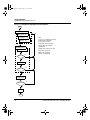
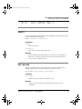
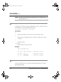
CodeWarrior Development Process
The CodeWarrior IDE helps you manage your development work more effectively than
you can with a traditional command-line environment. Figure 2.1 depicts application
development using the IDE.
ColdFire Architectures v6.0 - Targeting Manual
19
CF.book Page 20 Friday, July 8, 2005 8:59 AM
Getting Started
CodeWarrior Development Process
Figure 2.1 CodeWarrior IDE Application Development
Start
Create/Manage Project
Manage Files (1)
Specify Target
(2)
Settings
Edit Files
(3)
(4)
Notes:
(1) Use any combination: stationery
(template) files, library files,
or your own source files.
(2) Compiler, linker, debugger
settings; target specification;
optimizations.
Build (Make) Project
(3) Edit source and resource files.
Compile Project
(4) Possible corrections:
adding a file, changing
settings, or editing a file.
no
Success?
yes
Link Project
no
Success?
yes
Debug Project
Error-Free?
no
yes
Release
End
20
ColdFire Architectures v6.0 - Targeting Manual
CF.book Page 21 Friday, July 8, 2005 8:59 AM
Getting Started
CodeWarrior Development Process
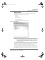
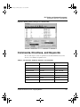
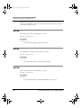
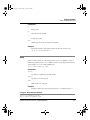
Project Files
A CodeWarrior project consists of source-code, library, and other files. The project
window (Figure 2.2) lists all files of a project, letting you:
• Add files
• Remove files
• Specify the link order
• Assign files to build targets
• Have the IDE generate debug information for files
Figure 2.2 Project Window
NOTE
Figure 2.2 shows a floating project window. Alternatively, you can dock the
project window in the IDE main window or make the project window a child of
the main window. You can have multiple project windows open at the same
time; if the windows are docked, their tabs let you control which one is at the
front of the main window.
The CodeWarrior IDE automatically handles dependencies among project files, storing
compiler and linker settings for each build target. The IDE tracks which files have
changed since your last build, recompiling only those files during your next project build.
A CodeWarrior project is analogous to a collection of makefiles, as the same project can
contain multiple builds. Examples are a debug version and release version of code, both
ColdFire Architectures v6.0 - Targeting Manual
21
CF.book Page 22 Friday, July 8, 2005 8:59 AM
Getting Started
CodeWarrior Development Process
part of the same project. As earlier text explained, build targets are such different builds
within a single project.
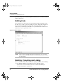
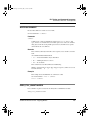
Editing Code
The CodeWarrior text editor handles text files in MS-DOS, UNIX, and MacOS formats.
To edit a source code file (or any other editable project file), double-click its filename in
the project window. The IDE opens the file in the editor window (Figure 2.3). This
window lets you switch between related files, locate particular functions, mark locations
within a file, or go to a specific line of code.
Figure 2.3 Editor Window
NOTE
Figure 2.3 shows a floating editor window. Alternatively, you can dock the
project window in the IDE main window or make the project window a child of
the main window.
Building: Compiling and Linking
For the CodeWarrior IDE, building includes both compiling and linking. To start building,
you select Project > Make, from the IDE main menu bar. The IDE compiler:
• Generates an object-code file from each source-code file of the build target,
incorporating appropriate optimizations.
22
ColdFire Architectures v6.0 - Targeting Manual
CF.book Page 23 Friday, July 8, 2005 8:59 AM
Getting Started
CodeWarrior Development Process
• Updates other files of the build target, as appropriate.
• In case of errors, issues appropriate messages and halts.
When compilation is done, building moves on to linking. The IDE linker:
• Links the object files into one executable file, in the link order you specify.
• In case of errors, issues appropriate error messages and halts.
When linking is done, you are ready to test and debug your application.
NOTE
It is possible to compile a single source file. To do so, select the filename in the
project window, then select Project > Compile from the main menu bar.
Another useful option is compiling only the modified files of the build target:
select Project > Bring Up To Date from the main menu bar.
Debugging
To debug your application, select Project > Debug from the main menu bar. The
debugger window opens, displaying your program code.
Run the application from within the debugger to observe results. The debugger lets you set
breakpoints, to check register, parameter, and other values at specific points of code
execution.
NOTE
To debug code stored in Flash memory, you first must program the Flash.
When your code executes correctly, you are ready to add features, to release the
application to testers, or to release the application to customers.
NOTE
Another debugging feature of the CodeWarrior IDE is viewing preprocessor
output. This helps you track down bugs caused by macro expansions or another
subtlety of the preprocessor. To use this feature, specify the output filename in
the project window, then select Project > Preprocess from the main menu bar.
A new window opens to show the preprocessed file.
Disassembling
To disassemble a compiled or ELF file of your project, select the file’s name in the project
window, then select Project > Disassemble. After disassembling the file, the
CodeWarrior IDE creates a .dump file that contains the disassembled file’s object code in
assembly format, and debugging information in Debugging With Attribute Record Format
(DWARF). The .dump file’s contents appear in a new window.
ColdFire Architectures v6.0 - Targeting Manual
23
CF.book Page 24 Friday, July 8, 2005 8:59 AM
Getting Started
CodeWarrior Development Process
24
ColdFire Architectures v6.0 - Targeting Manual
CF.book Page 25 Friday, July 8, 2005 8:59 AM
3
Application Tutorial
This chapter takes you through the CodeWarrior™ IDE programming environment. This
tutorial does not teach you programming. It instead teaches you how to use the
CodeWarrior IDE to write and debug applications for a target platform.
Before you start the tutorial, you must set up your target evaluation board (EVB).
Typically, this entails:
• Verifying all jumper-header and switch settings,
• Connecting a serial cable between the EVB and your computer, and
• Connecting EVB power.
NOTE
For complete setup instructions, see the EVB’s own documentation.
This chapter consists of these sections:
• Create a Project
• Build the Project
• Debug the Application
Create a Project
This section shows how to use stationery to create a new project for a ColdFire EVB, and
how to set up the project to make a standalone application. Follow these steps:
ColdFire Architectures v6.0 - Targeting Manual
25
CF.book Page 26 Friday, July 8, 2005 8:59 AM
Application Tutorial
Create a Project
1. Select Programs > Metrowerks CodeWarrior > CodeWarrior for ColdFire
V6.0 > CodeWarrior IDE. The CodeWarrior IDE starts and the main window
(Figure 3.1) appears.
Figure 3.1 CodeWarrior IDE Main Window
26
ColdFire Architectures v6.0 - Targeting Manual
CF.book Page 27 Friday, July 8, 2005 8:59 AM
Application Tutorial
Create a Project
2. From the main menu bar, select File > New. The New dialog box (Figure 3.2)
appears.
Figure 3.2 New Dialog Box
a. Select ColdFire Stationery.
b. In the Project name text box, type MyProj.
NOTE
The default project location is the CodeWarrior installation directory. For
example, if the project name is abc and the installation directory is
CodeWarrior_Dir, the default location is CodeWarrior_Dir\abc.
For a different location, click the Set button, then use the subsequent dialog
box to specify the location. Clicking OK returns you to the New dialog box,
which shows the specified location in the Location text box.
ColdFire Architectures v6.0 - Targeting Manual
27
CF.book Page 28 Friday, July 8, 2005 8:59 AM
Application Tutorial
Create a Project
c. Click OK. The New Project dialog box (Figure 3.3) appears.
Figure 3.3 New Project Dialog Box
3. Specify CF_M5213EVB C stationery.
a. Click the CF_M5213EVB expand control — the tree structure displays the
subordinate option C.
b. Select C, as Figure 3.4 shows.
Figure 3.4 New Project Dialog Box: Selecting M5213 C Stationery
NOTE
28
Many possible ColdFire target processors have an external bus, so can use
large external RAM devices for debugging applications during development.
But M521x processors do not have an external bus, so must accommodate
applications in on-chip memory. Although this on-chip RAM accommodates
CodeWarrior stationery, it probably is too small for full development of your
application. Accordingly, for an M521x processor, you should locate your
ColdFire Architectures v6.0 - Targeting Manual
CF.book Page 29 Friday, July 8, 2005 8:59 AM
Application Tutorial
Create a Project
applications in flash memory. (The Flash Programmer subsection explains how
to program a flash device.)
c. Click OK. The CodeWarrior IDE creates a new project consisting of the folders
and files (header, initialization, common, and so forth) that the M5213 C stationery
specifies. The project window (Figure 3.5) appears.
Figure 3.5 Project Window
4. Make sure that the target field (immediately under the project-window tab) specifies
M5213EVB Console Debug.
NOTE
Files in the project data folder include information about the project file,
various target settings, and object code. Do not change the contents of this
folder, or the CodeWarrior IDE could lose project settings.
5. This completes project creation. You are ready to build the project, per the procedure
of the next section.
NOTE
While your source file (main.c) is open in the editor window, you can use all
editor features to work with your code.
If you wish, you can use a third-party editor to create and edit your code,
provided that this editor saves the file as plain text.
For information about the editor window, touching files, and file
synchronization, and removing/adding text files, see IDE User’s Guide.
ColdFire Architectures v6.0 - Targeting Manual
29
CF.book Page 30 Friday, July 8, 2005 8:59 AM
Application Tutorial
Build the Project
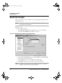
Build the Project
This section shows how to select the linker, set up remote debugging, and build (compile
and link) your project.
NOTE
The stationery for this project includes a default setup for the linker specific to
the application’s target platform.
Follow these steps:
1. Select the appropriate linker.
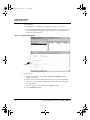
a. Select Edit > Target Settings (where Target is the name of the current build
target). The Target Settings window (Figure 3.6) appears.
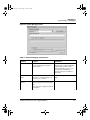
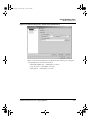
Figure 3.6 Target Settings Window: Target Settings Panel
b. From the Target Settings Panels list, select Target Settings. The Target Settings
panel moves to the front of the window.
c. Use the Linker list box to specify the Embedded ColdFire Linker.
d. Click Apply. The IDE saves the new linker setting for the build target.
NOTE
30
This linker change applies only to the current build target. To use a different
build target, you must specify its appropriate linker.
ColdFire Architectures v6.0 - Targeting Manual
CF.book Page 31 Friday, July 8, 2005 8:59 AM
Application Tutorial
Build the Project
For an actual target board, instead of the simulator, you would need to make
board connections by this point.
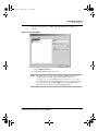
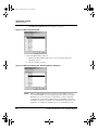
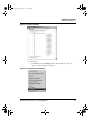
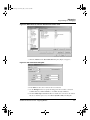
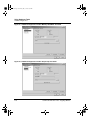
2. Set Up Remote Debugging.
a. From the Target Settings Panels list, select Remote Debugging. The Remote
Debugging settings panel moves to the front of the Target Settings window, as
Figure 3.7 shows.
Figure 3.7 Target Settings Window: Remote Debugging Panel
b. Use the Connection list box to specify CCS-SIM.
c. Click OK. The IDE completes the remote debugging setup, and the Target
Settings window closes.
3. From the main menu bar, select Project > Make. The IDE updates all files, links code
into the finished application, and displays any error messages or warnings in the
Errors & Warnings window.
NOTE
The Make command applies to all source files: the IDE opens them all, the
compiler generates object code, then the linker creates an executable file.
(The Compile command applies only to selected files. The Bring Up To Date
command compiles all changed files, without linking.)
The Project window lets you view compiler progress, or stop the build.
ColdFire Architectures v6.0 - Targeting Manual
31
CF.book Page 32 Friday, July 8, 2005 8:59 AM
Application Tutorial
Debug the Application
4. This completes building your project. You are ready for the debugging procedure of
the next section.
Debug the Application
This section explains you how to test whether your application runs as you expect. Topics
include starting the debugger, setting a breakpoint, and viewing registers. Follow these
steps:
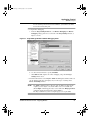
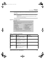
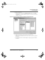
1. Set debugger preferences.
a. Select Edit > Target Settings, (where Target is the name of the current build
target). The Target Settings window appears.
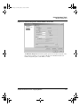
b. From the Target Settings Panels list, select CF Debugger Settings. The CF
Debugger Settings panel moves to the front of the window, as Figure 3.8 shows.
Figure 3.8 The CF Debugger Settings Panel
c. Make sure that the Target Processor list box specifies 521x.
d. Make sure that the Target OS list box specifies BareBoard.
e. Click OK. The IDE saves the debugger settings, and the Target Settings window
closes.
32
ColdFire Architectures v6.0 - Targeting Manual
CF.book Page 33 Friday, July 8, 2005 8:59 AM
Application Tutorial
Debug the Application
NOTE
The default target initialization and memory configuration files are in
subdirectory \E68K_Support\Initialization_Files, of the
CodeWarrior installation directory.
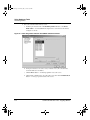
2. From the IDE main menu, select Project > Debug. A progress bar appears as the
system downloads the output file to the target. The debugger starts; the Debugger
window (Figure 3.9) appears.
NOTE
For a ROM build target, you must load the application to Flash memory before
you can perform Step 2.
Figure 3.9 Debugger Window
a. Note the toolbar at the top of the window; it includes command buttons Run, Stop,
Kill, Step Over, Step Into, and Step Out.
b. Note the Stack pane, at the upper left. This pane shows the function calling stack.
c. Note the Variables pane, at the upper right. This pane lists the names and values of
any local variables.
d. Note the Source pane, the largest pane of the window. This pane displays source
code or assembly code.
ColdFire Architectures v6.0 - Targeting Manual
33
CF.book Page 34 Friday, July 8, 2005 8:59 AM
Application Tutorial
Debug the Application
3. Set a breakpoint.
a. In the Source pane, find the line containing the open brace ( { ) character.
b. In the far left-hand column of this line, click the grey dash. A red circle replaces the
dash, indicating that the debugger set a breakpoint at the location. Figure 3.10
shows the red-circle indicator.
Figure 3.10 Setting a breakpoint
Breakpoint
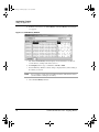
4. View registers.
a. From the main menu bar, select View > Registers. The Registers window
(Figure 3.11) appears.
b. Use the expand controls to drill down through register categories to individual
registers — when you reach individual registers, their values appear at the right
side of the window.
c. You may edit register values directly in the Registers window.
d. Close the Registers window.
34
ColdFire Architectures v6.0 - Targeting Manual
CF.book Page 35 Friday, July 8, 2005 8:59 AM
Application Tutorial
Debug the Application
Figure 3.11 Registers Window
5. View memory.
a. In the Source pane of the Debugger window, right-click on main. The viewmemory context menu (Figure 3.12) appears.
Figure 3.12 View Memory Context Menu
ColdFire Architectures v6.0 - Targeting Manual
35
CF.book Page 36 Friday, July 8, 2005 8:59 AM
Application Tutorial
Debug the Application
b. From this context menu, select View Memory. The View Memory window Figure
3.13 appears.
Figure 3.13 View Memory Window
c. Note that the View Memory window displays hexadecimal and ascii values for
several addresses, starting at the address of main.
d. In the Display text box, type a valid address in RAM or ROM.
e. Press the Enter key. Window contents change, to display memory values starting at
the address you entered.
NOTE
You can edit the contents of the View Memory window. This window also lets
you disassemble a random part of memory.
f. Close the View Memory window.
36
ColdFire Architectures v6.0 - Targeting Manual
CF.book Page 37 Friday, July 8, 2005 8:59 AM
Application Tutorial
Debug the Application
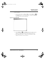
6. Run the application.
a. From the main menu bar, select Project > Run, or click the Run button
of
the Debugger window. A console window (Figure 3.14) appears, displaying the
Hello-World-message result of the application.
Figure 3.14 Console Window
b. Click the Kill button
of the Debugger window. The debugger stops the
application, the IDE stops the debugger, and the Debugger widow closes.
c. This completes the procedure — you have created and debugged a simple
application. You may close any open windows.
ColdFire Architectures v6.0 - Targeting Manual
37
CF.book Page 38 Friday, July 8, 2005 8:59 AM
Application Tutorial
Debug the Application
38
ColdFire Architectures v6.0 - Targeting Manual
CF.book Page 39 Friday, July 8, 2005 8:59 AM
4
Target Settings
This chapter explains the settings panels specific to ColdFire software development. Use
the elements of these panels to control assembling, compiling, linking, and other aspects
of code generation.
This chapter consists of these sections:
• Target Settings Overview
• ColdFire Settings Panels
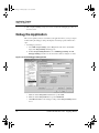
Target Settings Overview
In a CodeWarrior project, each build target has its own settings for compiling, linking, and
other parts of code generation. Your controls for these settings are the target settings
panels that you access through the Target Settings window.
To open this window, select Edit > Target Settings, from the main-window menu bar.
(Target is a target name, such as CF_Simulator, within your CodeWarrior project.) An
alternate way to brig up the Target Settings window is to bring the Targets page to the
front of the project window, then double-click the project name.
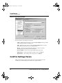
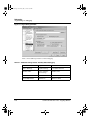
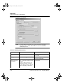
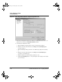
Figure 4.1 shows this Target Settings window. (The CodeWarrior IDE User’s Guide
explains all elements of this window.)
Use the tree listing of panels, in the Target Settings Panels pane, to display any settings
panel. If necessary, click the expand control to see a category’s list of panels. Clicking a
panel name immediately puts that panel in the Target Settings pane.
ColdFire Architectures v6.0 - Targeting Manual
39
CF.book Page 40 Friday, July 8, 2005 8:59 AM
Target Settings
ColdFire Settings Panels
Figure 4.1 Target Settings Window
Note these buttons, at the bottom of the window:
• Apply — Implements your changes, leaving the Target Settings window open. This
lets you bring up a different settings panel.
• OK — Implements your changes, closing the Target Settings window. Use this
button when you make the last of your settings changes.
• Revert — Changes panel settings back to their most recently saved values.
(Modifying any panel settings activates this button.)
• Factory Settings — Restores the original default values for the panel.
• Import Panel — Copies panel settings previously saved as an XML file.
• Export Panel — Saves settings of the current panel to an XML file.
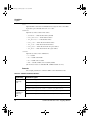
ColdFire Settings Panels
Table 4.1 lists the target settings panels specific to developing applications for the
ColdFire target. The following section describes these panels in detail.
40
ColdFire Architectures v6.0 - Targeting Manual
CF.book Page 41 Friday, July 8, 2005 8:59 AM
Target Settings
ColdFire Settings Panels
Table 4.1 ColdFire Target Settings Panels
Target Settings
ColdFire Processor
BatchRunner PreLinker
ELF Disassembler
BatchRunner PostLinker
ColdFire Linker
ColdFire Target
Debugger PIC Settings
ColdFire Assembler
NOTE
For debugger-specific panels CF Debugger Setting, CF Exceptions,
Debugger Settings, and Remote Debugging, see the Debugging chapter.
For information about the C/C++ Language and C/C++ Warnings panels,
see the C Compilers Reference manual.
For details on all other panels, see the IDE User’s Guide.
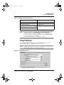
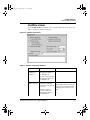
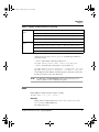
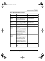
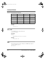
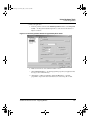
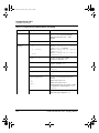
Target Settings
Use the Target Settings panel (Figure 4.2) to define the build target and select the
appropriate linker. Table 4.2 explains the elements of this panel.
NOTE
You must use this settings panel to select a linker before you can specify the
compiler, linker settings, or any other project details.
Figure 4.2 Target Settings Panel
ColdFire Architectures v6.0 - Targeting Manual
41
CF.book Page 42 Friday, July 8, 2005 8:59 AM
Target Settings
ColdFire Settings Panels
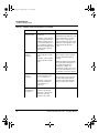
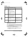
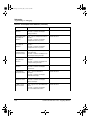
Table 4.2 Target Settings Panel Elements
Element
Purpose
Comments
Target Name text
box
Specifies the name of the build
target; this name appears
subsequently on the Targets
page of the project window.
Default: None.
Linker list box
Specifies the linker: Select
ColdFire.
Default: ColdFire.
Specifies the pre-linker that
performs work on object code
before linking.
Default: None.
Specifies the post-linker that
performs additional work on the
final executable.
Default: None.
Output Directory
text box
Specifies the directory for the
final linked output file. To specify
a non-default directory, click the
Choose button. To clear this text
box, click the Clear button.
Default: Directory that
contains the project file.
Save project
entries using
relative paths
checkbox
Clear — Specifies minimal file
searching; each project file must
have a unique name.
Default: Clear.
Pre-linker list box
Post-linker list box
42
This build-target name is not
the name of your final output
file.
Controls visibility of other
relevant panels.
If your project includes Flash
programming, select
BatchRunner PreLinker. For
more information, see
BatchRunner PreLinker.
Post-linking often includes
object code format
conversion. If your project
includes Flash programming,
select BatchRunner
PostLinker. For more
information, see BatchRunner
PostLinker.
Checked — Specifies relative file
searching; project may include
two or more files that have the
same name.
ColdFire Architectures v6.0 - Targeting Manual
CF.book Page 43 Friday, July 8, 2005 8:59 AM
Target Settings
ColdFire Settings Panels
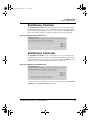
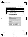
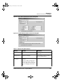
BatchRunner PreLinker
The BatchRunner PreLinker settings panel (Figure 4.3) lets you run a batch file before
the IDE begins linking your project. To specify such a batch file, click the Choose button,
then use the subsequent dialog box to navigate to and select the file. Clicking the OK
button of the dialog box returns you to this panel, filling in the name of the batch file.
Figure 4.3 BatchRunner PreLinker Panel
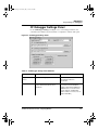
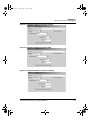
BatchRunner PostLinker
The BatchRunner PostLinker settings panel (Figure 4.4) lets you run a batch file after
the IDE builds your project. To specify such a batch file, click the Choose button, then use
the subsequent dialog box to navigate to and select the file. Clicking the OK button of the
dialog box returns you to this panel, filling in the name of the batch file.
Figure 4.4 BatchRunner PostLinker Panel
To pass the name of the output file as a parameter to the batch file, check the Pass linker
output file as %1 parameter to batch file checkbox.
ColdFire Architectures v6.0 - Targeting Manual
43
CF.book Page 44 Friday, July 8, 2005 8:59 AM
Target Settings
ColdFire Settings Panels
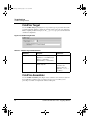
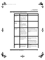
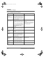
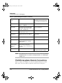
ColdFire Target
Use the ColdFire Target panel (Figure 4.5) to specify the type of project file and to name
your final output file. Table 4.3 explains the elements of this panel. (To create alternative
builds, compiling for different targets, use the __option() pre-processor function with
conditional compilation.)
Figure 4.5 ColdFire Target Panel
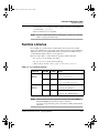
Table 4.3 ColdFire Target Panel Elements
Element
Purpose
Comments
Project Type list box
Specifies the kind of project:
Application — executable project
Library — static library
Shared Library — shared library
Default: Application.
File Name text box
Specifies the name of your final
linked output file.
Default: None.
Convention: use
extension.elf for an
application, .lib or .a
for a library.
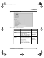
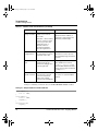
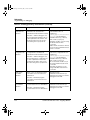
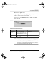
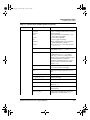
ColdFire Assembler
Use the ColdFire Assembler panel (Figure 4.6) to control the source format or syntax for
the CodeWarrior assembler, and to specify the target processor, for which you are
generating code. Table 4.4 explains the elements of this panel.
44
ColdFire Architectures v6.0 - Targeting Manual
CF.book Page 45 Friday, July 8, 2005 8:59 AM
Target Settings
ColdFire Settings Panels
Figure 4.6 ColdFire Assembler Panel
Table 4.4 ColdFire Assembler Panel Elements
Element
Purpose
Comments
Processor list box
Specifies the target processor.
Default: MCF52xx.
Processor has MAC
checkbox
Clear — Tells assembler that the target
processor does not have a multiply
accumulator (MAC) unit.
Default: Clear.
Checked — Tells assembler that the
target processor does have a MAC.
Processor has EMAC
checkbox
Clear — Tells assembler that the target
processor does not have an enhanced
multiply accumulator (EMAC) unit.
For more information, see the
reference manual at
{CodeWarrior_Dir}
\Freescale_Documentation,
You can check both
the MAC and
EMAC checkboxes.
Default: Clear.
You can check both
the MAC and
EMAC checkboxes.
Checked — Tells assembler that the
target processor does have EMAC.
ColdFire Architectures v6.0 - Targeting Manual
45
CF.book Page 46 Friday, July 8, 2005 8:59 AM
Target Settings
ColdFire Settings Panels
Table 4.4 ColdFire Assembler Panel Elements (continued)
Element
Purpose
Comments
Processor has FPU
checkbox
Clear — Tells assembler that the target
processor does not have a floatingpoint unit (FPU).
Default: Clear
Checked — Tells assembler that the
target processor does have an FPU.
Labels Must End With
‘:’ checkbox
Clear — System does not require
labels to end with colons.
Default: Checked.
Checked — System does require
labels to end with colons.
Directives Begin With
‘:’ checkbox
Clear — System does not require
directives to start with periods.
Default: Checked.
Checked — System does require
directives to start with periods.
Case Sensitive
Identifiers checkbox
Clear — Tells assembler to ignore
case in identifiers.
Default: Checked.
Checked — Tells assembler to
consider case in identifiers.
Allow Space In
Operand Field
checkbox
46
Clear — Tells assembler to not allow
spaces in operand fields.
Default: Checked.
Checked — Tells assembler to allow
spaces in operand fields.
ColdFire Architectures v6.0 - Targeting Manual
CF.book Page 47 Friday, July 8, 2005 8:59 AM
Target Settings
ColdFire Settings Panels
Table 4.4 ColdFire Assembler Panel Elements (continued)
Element
Purpose
Comments
Generate Listing File
checkbox
Clear — Tells assembler to not
generate a listing file.
Default: Clear.
Checked — Tells assembler to
generate a listing file.
Prefix File text box
Specifies the name of the assembly
prefix file.
A listing file
contains the file
source, along with
line numbers,
relocation
information, and
macro expansions.
Default: None.
Useful for include
files that define
common constants,
global declarations,
and function
names. Otherwise,
the assembler’s
default prefix file
suffices.
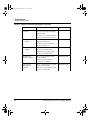
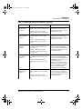
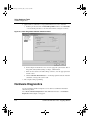
ELF Disassembler
Use the ELF Disassembler panel (Figure 4.7) to control settings for the disassembly
view; you see this view when you disassemble object files. Table 4.5 explains the
elements of this panel.
ColdFire Architectures v6.0 - Targeting Manual
47
CF.book Page 48 Friday, July 8, 2005 8:59 AM
Target Settings
ColdFire Settings Panels
Figure 4.7 ELF Disassembler Panel
Table 4.5 ELF Disassembler Panel Elements
Element
Purpose
Comments
Show Headers
checkbox
Clear — Keeps ELF header
information out of the
disassembled output.
Default: Checked.
Checked — Puts ELF
header information into the
disassembled output.
Verbose Info
checkbox
Clear — Uses minimum
information in disassembled
output.
Checked — Puts additional
information into the
disassembled output.
Show Symbol and
String Tables
checkbox
Clear — Keeps symbol table
out of the disassembled
module.
Default: Clear.
For the .symtab section,
additional information
includes numeric equivalents
for descriptive constants. For
the .line, .debug, .extab,
and .extabindex sections,
additional information
includes an unstructured hex
dump.
Default: Checked.
Checked — Puts symbol
table into the disassembled
module.
48
ColdFire Architectures v6.0 - Targeting Manual
CF.book Page 49 Friday, July 8, 2005 8:59 AM
Target Settings
ColdFire Settings Panels
Table 4.5 ELF Disassembler Panel Elements (continued)
Element
Purpose
Comments
Show Relocations
checkbox
Clear — Keeps relocation
information out of the
disassembled module.
Default: Checked.
Checked — Puts relocation
information into the
disassembled module.
Show Code Modules
checkbox
Clear — Keeps any of the
four types of ELF code
sections out the
disassembled module;
disables the four subordinate
checkboxes.
Relocation information
pertains to the .real.text
and .reala.data sections.
Default: Checked.
Checked — Activates the
four subordinate
checkboxes. For each
checked subordinate
checkbox, puts ELF code
section into the
disassembled module.
Use Extended
Mnemonics checkbox
Clear — Keeps extended
mnemonics out of the
disassembled module.
Checked — Puts instruction
extended mnemonics into
the disassembled module.
Show Source Code
checkbox
Clear — Keeps source code
out of the disassembled
module.
Checked — Lists source
code in the disassembled
module. Display is mixed
mode, with line-number
information from original C
source code.
ColdFire Architectures v6.0 - Targeting Manual
Default: Checked.
This checkbox is active only if
the Show Code Modules
checkbox is checked.
Default: Checked.
This checkbox is active only if
the Show Code Modules
checkbox is checked.
49
CF.book Page 50 Friday, July 8, 2005 8:59 AM
Target Settings
ColdFire Settings Panels
Table 4.5 ELF Disassembler Panel Elements (continued)
Element
Purpose
Comments
Show Addresses and
Object Code checkbox
Clear — Keeps addresses
and object code out of the
disassembled module.
Default: Checked.
Checked — Lists addresses
and object code in the
disassembled module.
Show Comments
checkbox
Clear — Keeps
disassembler comments out
of the disassembled module.
Checked — Shows
disassembler comments in
sections that have comment
columns.
Show Data Modules
checkbox
Clear — Blocks output of
ELF data sections for the
disassembled module;
disables the Disassemble
Exception Tables checkbox.
This checkbox is active only if
the Show Code Modules
checkbox is checked.
Default: Checked.
This checkbox is active only if
the Show Code Modules
checkbox is checked.
Default: Checked.
Checked — Outputs
.rodata, .bss, or other
such ELF data sections in
the disassembled module.
Activates the Disassemble
Exception Tables checkbox.
Disassemble
Exception Tables
checkbox
Clear — Keeps C++
exception tables out of the
disassembled module.
Checked — Includes C++
exception tables in the
disassembled module.
Show Debug Info
checkbox
Clear — Keeps DWARF
symbolics out of the
disassembled module.
Default: Clear.
This checkbox is active only if
the Show Data Modules
checkbox is checked.
Default: Clear.
Checked — Includes
DWARF symbolics in the
disassembled module.
50
ColdFire Architectures v6.0 - Targeting Manual
CF.book Page 51 Friday, July 8, 2005 8:59 AM
Target Settings
ColdFire Settings Panels
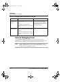
ColdFire Processor
Use the ColdFire Processor panel (Figure 4.8) to control code-generation settings. Table
4.6 explains the elements of this panel.
Figure 4.8 ColdFire Processor Panel
Table 4.6 ColdFire Processor Panel Elements
Element
Purpose
Comments
Target CPU list
box
Specifies the target ColdFire
processor.
Default: MCF5282.
Code Model list
box
Specifies access addressing for
data and instructions in the object
code:
Default: Far (32 bit).
Smart — Relative (16-bit) for
function calls in the same
segment; otherwise absolute (32bit).
Near (16 bit) — Relative for all
function calls.
Far is useful if your source
file generates more than 32K
of code, or if there is an outof-range link error message.
Near requires adjusting the
.lcf. For .lcf information,
see LCF Structure
Far (32 bit) — Absolute for all
function calls.
ColdFire Architectures v6.0 - Targeting Manual
51
CF.book Page 52 Friday, July 8, 2005 8:59 AM
Target Settings
ColdFire Settings Panels
Table 4.6 ColdFire Processor Panel Elements (continued)
Element
Purpose
Comments
Struct Alignment
list box
Specifies record and structure
alignment in memory:
Default: 68k 4-byte.
68K 2-byte — Aligns all fields on
2-byte boundaries, except for
fields of only 1 byte.
68K 4-byte — Aligns all fields on
4-byte boundaries.
PowerPC 1-byte — Aligns each
field on its natural boundary.
Data Model list
box
Specifies global-data storage and
reference:
Far (32 bit) — Storage in far data
space; available memory is the
only size limit.
This panel element
corresponds to the options
align pragma.
Natural-boundary alignment
means 1-byte for a 1-byte
character, 2-bytes for a 16bit integer, and so on.
NOTE: When you compile
and link, alignment should
be the same for all files and
libraries.
Default: Far (32 bit).
This panel element
corresponds the far_data
pragma.
Near (16 bit) — Storage in near
data space; size limit is 64K.
Parameter
Passing list box
Specifies parameter-passing
level:
Compact — Passes on evensized boundary for parameters
smaller than int (2 for short and
char).
Standard — Like compact, but
always padded to 4 bytes.
Register — Passes in scratch
registers D0 — D2 for integers, A0
— A1 for pointers and fp0 — fp1
when FPU codegen is selected;
this can speed up programs that
have many small functions.
52
Default: Compact.
These levels correspond to
the compact_abi,
standard_abi, and
register_abi pragmas.
NOTE: Be sure that all called
functions have prototypes.
When you compile and link,
parameter passing should
be the same for all files and
libraries.
ColdFire Architectures v6.0 - Targeting Manual
CF.book Page 53 Friday, July 8, 2005 8:59 AM
Target Settings
ColdFire Settings Panels
Table 4.6 ColdFire Processor Panel Elements (continued)
Element
Purpose
Comments
Floating Point list
box
Specifies handling method for
floating-point operations:
Default: Software.
Software — C runtime library code
emulates floating-point
operations.
For software selection, your
project must include the
appropriate FP_ColdFire
C runtime library file.
Hardware — Processor hardware
performs floating point operations;
only appropriate for processors
that have floating-point units.
Greyed out if your target
processor lacks an FPU.
4-Byte Integers
checkbox
Clear — Specifies 2-byte integers.
Default: Checked.
PositionIndependent
Code checkbox
Clear — Generates relocatable
code.
A6 Stack Frames
checkbox
Clear — Disables call-stack
tracing; generates faster and
smaller code.
Checked — Specifies 4-byte
integers.
Checked — Generates positionindependent code (PIC) that is
non-relocatable.
Checked — Enables call-stack
tracing; each stack frame sets up
and restores register A6.
PositionIndependent Data
checkbox
Clear — Generates relocatable
data.
Emit Macsbug
Symbols
checkbox
Clear — Does not generate
Macsbug symbols.
Checked — Generates positionindependent data (PID) that is
non-relocatable.
Checked — Generates Macsbug
symbols inside code after RTS
statements.
ColdFire Architectures v6.0 - Targeting Manual
Default: Clear.
PIC is available with 16- and
32-bit addressing.
Default: Checked.
Checking this checkbox
corresponds to using the
a6frames pragma.
Clearing this checkbox is
appropriate if you will not
use the debugger.
Default: Clear.
PID is available with 16- and
32-bit addressing.
Default: Clear.
A Macsbug symbol is the
routine name, appended
after the routine, in Pascal
format. These symbols are
appropriate only for older
debuggers.
53
CF.book Page 54 Friday, July 8, 2005 8:59 AM
Target Settings
ColdFire Settings Panels
Table 4.6 ColdFire Processor Panel Elements (continued)
Element
Purpose
Comments
PC-Relative
Strings checkbox
Clear — Does not use programcounter relative addressing for
storage of function local strings.
Default: Clear.
Checked — Does use programcounter relative addressing for
storage of function local strings.
Generate code
for profiling
Checked — Has the processor
generate code for use with a
profiling tool.
Clear — Prevents the processor
from generating code for use with
a profiling tool.
Use .sdata/.sbss
for area
All data — Select this option
button to store all data items in the
small data address space.
All data smaller than — Select this
option button to specify the
maximum size for items stored in
the small data address space;
enter the maximum size in the text
box.
54
Checking this box
corresponds to using the
pcrelstrings pragma.
Default: Clear.
Checking this box
corresponds to using the
command-line option
-profile.
Clearing this checkbox is
equivalent to using the
command-line option
-noprofile
Default: All data smaller
than/0.
Using the small data area
speeds data access, but has
ramifications for the
hardware memory map. The
default settings specify not
using the small data area.
ColdFire Architectures v6.0 - Targeting Manual
CF.book Page 55 Friday, July 8, 2005 8:59 AM
Target Settings
ColdFire Settings Panels
ColdFire Linker
Use the ColdFire Linker panel (Figure 4.9) to control the final form of your object code.
Table 4.7 explains the elements of this panel.
Figure 4.9 ColdFire Linker Panel
Table 4.7 ColdFire Linker Panel Elements
Element
Purpose
Comments
Generate
Symbolic Info
checkbox
Clear — Does not generate
debugging information in
the output ELF file.
Default: Checked.
Checked — Puts generated
debugging information into
the output ELF file.
Store Full Path
Names checkbox
Clear — In debugging
information in the linked
ELF file, uses only names of
source files.
Checked — Includes
source-file paths in the
debugging information in
the linked ELF file.
ColdFire Architectures v6.0 - Targeting Manual
Default: Checked.
Clearing this checkbox saves target
memory, but increases the time the
debugger needs to find the source
files.
55
CF.book Page 56 Friday, July 8, 2005 8:59 AM
Target Settings
ColdFire Settings Panels
Table 4.7 ColdFire Linker Panel Elements (continued)
Element
Purpose
Comments
Generate Link
Map checkbox
Clear — Does not generate
a link map.
Default: Checked.
Checked — Does generate
a link map (a text file that
identifies definition files for
each object and function of
your output file); activates
the List Unused Objects and
Show Transitive Closure
checkboxes.
List Unused
Objects
checkbox
Clear — Does not include
unused objects in the link
map.
Checked — Does include
unused objects in the link
map.
Show Transitive
Closure
checkbox
Clear — Does not include
the link map objects that
main() references.
Checked — Recursively
lists in the link map all
objects that main()
references.
Disable
Deadstripping
checkbox
56
Clear — Lets linker remove
unused code and data.
A link map includes addresses of all
objects and functions, a memory
map of sections, and values of
symbols the linker generates. A link
map has the same filename as the
output file, but with extension
.xMAP.
Default: Clear.
This checkbox is active only if the
Generate Link Map checkbox is
checked.
NOTE: The linker never deadstrips
unused assembler relocatables or
relocatables built with a nonCodeWarrior compiler. But
checking this checkbox gives you a
list of such unused items; you can
use this list to remove the symbols.
Default: Checked.
This checkbox is active only if the
Generate Link Map checkbox is
checked. Listings after this table
show the effect of this checkbox.
Default: Clear.
Checked — Prevents the
linker from removing
unused code or data.
ColdFire Architectures v6.0 - Targeting Manual
CF.book Page 57 Friday, July 8, 2005 8:59 AM
Target Settings
ColdFire Settings Panels
Table 4.7 ColdFire Linker Panel Elements (continued)
Element
Purpose
Comments
Generate ELF
Symbol Table
checkbox
Clear — Omits the ELF
symbol table and relocation
list from the ELF output file.
Default: Checked.
Checked — Includes an
ELF symbol table and
relocation list in the ELF
output file.
Suppress
Warning
Messages
checkbox
Clear — Reports all linker
warnings.
Generate SRecord File
checkbox
Clear — Does not generate
an S-record file.
Max S-Record
Length text box
Specifies maximum number
of bytes in S-record lines
that the linker generates.
The maximum value for this
text box is 252.
Default: Clear.
Checked — Reports only
fatal warning messages;
does not affect display of
messages from other parts
of the IDE.
Checked — Generates an
S3-type S-record file,
suitable for printing or
transportation to another
computer system. Activates
the Max S-Record text box
and the EOL character list
box.
Default: Checked.
The S-record has the same
filename as the executable file, but
with extension .S19, .S3 records
include code, data, and their 4-byte
addresses.
Default: 80.
This text box is active only if the
Generate S-Record File checkbox
is checked.
NOTE: Many embedded systems
limit S-record lines to 24 or 26
bytes. A value of 20 to 30 bytes lets
you see the S-record on a single
page.
EOL Character
list box
Specifies the end-of-line
character for the S-record
file, by operating system:
DOS, UNIX, or MAC.
ColdFire Architectures v6.0 - Targeting Manual
Default: DOS.
This text box is active only if the
Generate S-Record File checkbox
is checked.
57
CF.book Page 58 Friday, July 8, 2005 8:59 AM
Target Settings
ColdFire Settings Panels
Table 4.7 ColdFire Linker Panel Elements (continued)
Element
Purpose
Comments
Generate Binary
Image checkbox
Clear — Does not create a
binary version of the Srecord file.
Default: Clear.
Checked — Saves a binary
version of the S-record file
to the project folder; The
binary file has the .b
filename extension.
Activates the Max Bin
Record Length text box.
Binary file format is address (2
bytes), byte count (2 bytes), and
data bytes (variable length).
Max Bin Record
Length text box
Specifies data-byte length
for each binary record. The
maximum value is 252.
Default: None.
Entry Point text
box
Specifies the program
starting point: the first
function the debugger uses
upon program start.
Default: __start.
Force Active
Symbols text box
Specifies symbols to be
included in the output file
even if not referenced;
makes such symbols
immune from deadstripping.
Default: None.
This text box is active only if the
Generate Binary Image checkbox is
checked.
(This default function is in file
ColdFire__startup.c. It sets
up the ColdFire EABI environment
before code execution. Its final task
is calling main().
Use spaces to separate multiples
symbols.
Listing 4.1 and Listing 4.2 show the effect of the Show Transitive Closure checkbox.
Listing 4.1 Sample Code for Transitive Closure
void alpha1(){
int a = 1001;
}
void alpha(){
int b = 1002;
alpha1();
}
int main(void){
alpha();
58
ColdFire Architectures v6.0 - Targeting Manual
CF.book Page 59 Friday, July 8, 2005 8:59 AM
Target Settings
ColdFire Settings Panels
return 1;
}
If you checked the Show Transitive Closure checkbox of the ColdFire Linker panel and
compiled the source files,
• The linker would generate a link map file, and
• The link map file would include text such as that of Listing 4.2.
Listing 4.2 Link Map: Effects of Show Transitive Closure
# Link map of __start
1] __start (func, global) found in C_4i_CF_Runtime.a E68k_startup.o
2] __main (func, global) found in main.c
3] __alpha (func, global) found in main.c
4] __alpha1 (func, global) found in main.c
Debugger PIC Settings
Use the Debugger PIC Settings panel (Figure 4.10) to specify an alternate address where
you want your ELF image downloaded on the target.
Figure 4.10 Debugger PIC Settings Panel
Usually, Position Independent Code (PIC) is linked in such a way that the entire image
starts at address 0x00000000. To specify a different target address for loading the PIC
module:
1. Check the Alternate Load Address checkbox — this activates the text box.
2. Enter the address in the text box.
At download time, the debugger downloads your ELF file to this new address of the target.
NOTE
The debugger does not verify that your code can execute at the new address.
However, the PIC generation settings of the compiler and linker, and the
ColdFire Architectures v6.0 - Targeting Manual
59
CF.book Page 60 Friday, July 8, 2005 8:59 AM
Target Settings
ColdFire Settings Panels
startup routines of your code, correctly set any base registers and perform any
appropriate relocations.
60
ColdFire Architectures v6.0 - Targeting Manual
CF.book Page 61 Friday, July 8, 2005 8:59 AM
5
Compilers
This chapter explains issues of C and C++ code generation for the ColdFire target.
NOTE
Special-Edition software compiles assembly and C code, but the code size
must not exceed 128 kilobytes.
Standard-Edition software compiles assembly and C code, without any size
restriction.
Professional-Edition software compiles assembly, C, and C++ code, without
any size restriction.
This chapter consists of these sections:
• Language Extensions
• Integer Formats
• Calling Conventions
• Variable Allocation
• Register Variables
• Pragmas
• Predefined Symbols
• Position-Independent Code
Table 5.1 lists additional documents or chapters that provide information about code
generation.
Table 5.1 Additional CodeWarrior Compiler and Linker Documentation
Topic
Reference
CodeWarrior implementation of C/C++
C Compilers Reference
C/C++ Language and C/C++ Warnings
settings panels
C Compilers Reference: chapter Setting C/
C++ Compiler Options
Controlling C++ code size
C Compilers Reference: chapter C++ and
Embedded Systems
Using compiler pragmas
C Compilers Reference: chapter Pragmas
and Symbols
ColdFire Architectures v6.0 - Targeting Manual
61
CF.book Page 62 Friday, July 8, 2005 8:59 AM
Compilers
Language Extensions
Table 5.1 Additional CodeWarrior Compiler and Linker Documentation (continued)
Topic
Reference
Meeting EC++ specifications
C Compilers Reference
Initiating a build, controlling which files are
compiled, handling error reports
IDE User Guide: chapter Compiling and
Linking
Explanation of error messages
Error Reference
Inline assembly
Inline Assembly chapter of this Targeting
Manual
Standalone assembler
Assembler Reference
Language Extensions
This section explains the ColdFire-specific extensions to the standards of the CodeWarrior
C/C++ compiler.
You can disable some of these extensions by using options of the C/C++ Language panel,
which the C Compilers Reference manual explains.
PC-Relative Strings
The default compiler configuration is to store all string constants in the global data
segment. This configuration corresponds to a clear PC-Relative Strings checkbox of the
ColdFire Processor panel.
But to keep the global data segment smaller, you can check the PC-Relative Strings
checkbox. Configuring PC-relative strings means that the compiler:
• Stores local-scope string constants in the code segment
• Uses PC-relative instructions to address these strings
The PC-Relative Strings checkbox corresponds to the pragma pcrelstrings. To
check whether this pragma is in effect, use __option (pcrelstrings). Listing 5.1
shows an example of the pragma use.
Listing 5.1 Using PC-relative strings pragma
#pragma pcrelstrings on
int f(char *);
int bar()
{
return f("World"); // "World" allocated in code segment
62
ColdFire Architectures v6.0 - Targeting Manual
CF.book Page 63 Friday, July 8, 2005 8:59 AM
Compilers
Language Extensions
// (pc-relative)
}
#pragma pcrelstrings reset
Declaration Specifiers
A declaration specifier tells the compiler to override a default storage location, regardless
of the object’s size or initialization. The syntax is:
__declspec (sectionName) dataType objectName
where:
sectionName
Identifies the storage section for the object
dataType
Specifies the data type of the object
objectName
Is the name of the variable object to be stored
Listing 5.2 shows examples.
Listing 5.2 Using the __declspec() declaration specifier
// create a user-defined section ".mycode"
#pragma define_section mycode ".mycode" far_absolute RX
__declspec(bss)
int Large_Array_in_Small_Data_Section[1000];
__declspec(mycode) void Function_in_MyCode_Section()
{
printf("Hello from MyCode section!\n");
}
A declaration specifier may use any section, whether pre-defined or user-defined. (For
more information about pre-defined and user-defined sections, see define_section.)
A declaration specifier also can use an application binary interface (ABI). An ABI
corresponds directly to the parameter-passing option (Standard, Compact or Register) that
the ColdFire Processor Settings panel specifies. (For information about these ABIs, see
ColdFire Processor.)
ColdFire Architectures v6.0 - Targeting Manual
63
CF.book Page 64 Friday, July 8, 2005 8:59 AM
Compilers
Integer Formats
Integer Formats
The ColdFire compiler lets you specify the number of bytes that the compiler allocates for
an int. Bring up the ColdFire Processor settings panel, then use the 4-Byte Integers
option.
Table 5.2 shows the size and range of the integer types available for ColdFire targets.
Table 5.2 ColdFire Integer Types
Type
Option Setting
Size
Range
bool
n/a
8 bits
true or false
char
Use Unsigned
Chars is off in the
C/C++ Language
panel
8 bits
-128 to 127
Use Unsigned
Chars is on in the
C/C++ Language
panel
8 bits
0 to 255
signed char
n/a
8 bits
-128 to 127
unsigned
char
n/a
8 bits
0 to 255
short
n/a
16 bits
-32,768 to 32,767
unsigned
short
n/a
16 bits
0 to 65,535
int
4-Byte Integers is
off in the ColdFire
Processor panel
16 bits
-32,768 to 32,767
4-Byte Integers is
on in the ColdFire
Processor panel
32 bits
-2,147,483,648 to 2,147,483,647
4-Byte Integers is
off in the ColdFire
Processor panel
16 bits
0 to 65,535
4-Byte Integers is
on in the ColdFire
Processor panel
32 bits
0 to 4,294,967,295
unsigned int
64
ColdFire Architectures v6.0 - Targeting Manual
CF.book Page 65 Friday, July 8, 2005 8:59 AM
Compilers
Calling Conventions
Table 5.2 ColdFire Integer Types (continued)
Type
Option Setting
Size
Range
long
n/a
32 bits
-2,147,483,648 to 2,147,483,647
unsigned
long
n/a
32 bits
0 to 4,294,967,295
long long
n/a
64 bits
-9,223,372,036,854,775,808 to
9,223,372,036,854,775,807
unsigned
long long
n/a
64 bits
0 to 18,446,744,073,709,551,615
Calling Conventions
For ColdFire development, the calling conventions are:
• Standard — the compiler uses the default amount of memory, expanding everything
to int size.
• Compact — the compiler tries to minimize memory consumption.
• Register — the compiler tries to use memory registers, instead of the stack.
NOTE
The corresponding levels for the supported calling conventions are
standard_abi (the default), compact_abi, and register_abi.
For more ABI information, see ColdFire Processor Panel Elements.
The compiler passes parameters on the stack in reverse order. It passes the return value in
different locations, depending on the nature of the value and compiler settings:
• Integer return value: register D0.
• Pointer return value: register A0.
• Any other return value: temporary storage area. (For any non-integer, non-pointer
return type, the calling routine reserves this area in its stack. The calling routine
passes a pointer to this area as its last argument. The called function returns its value
in this temporary storage area.)
To have the compiler return pointer values in register D0, use the pragma
pointers_in_D0, which the C Compiler reference guide explains.
To reset pointer returns, use the pragma pointers_in_A0.
ColdFire Architectures v6.0 - Targeting Manual
65
CF.book Page 66 Friday, July 8, 2005 8:59 AM
Compilers
Variable Allocation
NOTE
If you use the pragma pointers_in_A0, be sure to use correct prototypes.
Otherwise, the pragma may not perform reliably.
Figure 5.1 depicts the stack when you use the ColdFire compiler to call a C function.
Figure 5.1 Calling a C Function: Stack Depiction
Last Argument
...
First Argument
Pointer to Return Value (if needed)
Stack Pointer
Return Address
Variable Allocation
For a ColdFire target, the compiler lets you declare structs and arrays to be any size, but
imposes a few limits on how you allocate their space:
• Maximum bitfield size is 32 bits.
• There is no limit to local-variable space for a function. However, access is twice as
fast for frames that do not exceed 32 kilobytes. To keep within this limit,
– Dynamically allocate large variables, or
– Declare large variables to be static (provided that this does not exceed the 32kilobyte limit on global variables).
• Maximum declaration size for a global variable is 32 kilobytes, unless you use far
data. You must do one of the following:
– Dynamically allocate the variable.
– Use the far qualifier when declaring the variable.
– Select the Far (32 bit) option from the Code and Data model in the ColdFire
Processor settings panel.
Listing 5.3 shows how to declare a large struct or array. Keep in mind that declaring large
static arrays works only if the device has enough physical memory.
Listing 5.3 Declaring a large structure
int i[50000]; // Wrong with ColdFire compiler and the Far Data
// option in the Processor settings panel is off
far int j[50000]; // ALWAYS OK.
66
ColdFire Architectures v6.0 - Targeting Manual
CF.book Page 67 Friday, July 8, 2005 8:59 AM
Compilers
Register Variables
int *k;
k = malloc(50000 * sizeof(int));
// ALWAYS OK.
Register Variables
The ColdFire back-end compiler automatically allocates local variables and parameters to
registers, according to frequently of use and how many registers are available.
The ColdFire compiler can use these registers for local variables:
• A2 through A5 — for pointers
• D3 through D7 — for integers and pointers.
• FP3 through FP7 — for 64-bit floating-point numbers (provided that you select
Hardware in the Floating Point list box of the ColdFire Processor panel).
If you optimize for speed, the compiler gives preference to variables in loops.
The ColdFire back-end compiler gives preference to variables declared register, but
does not automatically assign them to registers. For example, if the compiler must choose
between an inner-loop variable and a variable declared register, the compiler places
the inner-loop variable in the register.
Pragmas
For ColdFire development, the compiler supports the standard pragmas that Table 5.3
lists. The C Compilers Reference explains these pragmas, including their syntax.
Table 5.3 Standard Pragmas for ColdFire Development
a6frames
auto_inline
align_array_members
align
ARM_conform
cpp_extensions
bool
dont_reuse_strings
cplusplus
exceptions
direct_destruction
far_data
enumsalwaysints
force_active
extended_errorcheck
ignore_oldstyle
ColdFire Architectures v6.0 - Targeting Manual
67
CF.book Page 68 Friday, July 8, 2005 8:59 AM
Compilers
Pragmas
Table 5.3 Standard Pragmas for ColdFire Development (continued)
far_vtables
lib_export
IEEEdoubles
macsbug, oldstyle_symbols
inline_depth
mpwc_newline
longlong
once
mark
optimize_for_size
mpwc_relax
pcrelstrings
only_std_keywords
pointers_in_D0
parameter
precompile_target
pointers_in_A0
require_prototypes
pool_strings
segment
profile
static_inlines
RTTI
unsigned_char
unused
warn_emptydecl
warn_hidevirtual
warn_illpragma
warn_unusedarg
ANSI_strict
The compiler also supports pragmas that are new — or have new definitions — for
ColdFire development. Table 5.4 lists these new pragmas; following text explains them.
Table 5.4 New Pragmas for ColdFire Development
68
codeColdFire
const_multiply
define_section
emac
explicit_zero_data
interrupt
opt_unroll_count
opt_unroll_instr_count
Predefined Symbols
readonly_strings
SDS_debug_support
section
ColdFire Architectures v6.0 - Targeting Manual
CF.book Page 69 Friday, July 8, 2005 8:59 AM
Compilers
Pragmas
codeColdFire
Controls organization and generation of ColdFire object code.
#pragma codeColdFire processor
Parameter
processor
Any of these specifier values: MCF521x, MCF5206e, MCF5249, MCF5272,
MCF5282, MCF5307, MCF5407, MCF547x, MCF548x — or reset, which
specifies the default processor.
const_multiply
Enables support for constant multiplies, using shifts and add/subtracts.
#pragma const_multiply [ on | off | reset ]
Remarks
The default value is on.
define_section
Specifies a predefined section or defines a new section for compiled object code.
#pragma define_section sname ".istr" [.ustr] [addrmode]
[accmode]
Parameters
sname
Identifier for source references to this user-defined section.
istr
Section-name string for initialized data assigned to this section. Double quotes
must surround this parameter value, which must begin with a period. (Also applies
to uninitialized data if there is no ustr value.)
ColdFire Architectures v6.0 - Targeting Manual
69
CF.book Page 70 Friday, July 8, 2005 8:59 AM
Compilers
Pragmas
ustr
Optional: ELF section name for uninitialized data assigned to this section. Must
begin with a period. Default value is the istr value.
addrmode
Optional: any of these address-mode values:
• standard — 32-bit absolute address (default)
• near_absolute — 16-bit absolute address
• far_absolute — 32-bit absolute address
• near_code — 16-bit offset from the PC address
• far_code — 32-bit offset from the PC address
• near_data — 16-bit offset from the A5 register address
• far_data — 32-bit offset from the A5 register address
accmode
Optional: any of these letter combinations:
• R — readable
• RW — readable and writable
• RX — readable and executable
• RWX — readable, writable, and executable (default)
(No other letter orders are valid: WR, XR, or XRW would be an error.)
Remarks
The compiler predefines the common ColdFire sections that Table 5.5 lists.
Table 5.5 ColdFire Predefined Sections
Applicability
Definition Pragmas
Absolute
Addressing
Mode
#pragma define_section text ".text" far_absolute RX
#pragma define_section data ".data" ".bss" far_absolute RW
#pragma define_section sdata ".sdata" ".sbss" near_data RW
#pragma define_section const ".rodata" far_absolute R
C++,
Regardless of
Addressing
Mode
70
#pragma define_section exception ".exception" far_absolute R
#pragma define_section exceptlist ".exceptlist" far_absolute R
ColdFire Architectures v6.0 - Targeting Manual
CF.book Page 71 Friday, July 8, 2005 8:59 AM
Compilers
Pragmas
Table 5.5 ColdFire Predefined Sections (continued)
PID Addressing
Mode
#pragma define_section text ".text" far_absolute RX
#pragma define_section data ".data" ".bss" far_data RW
#pragma define_section sdata ".sdata" ".sbss" near_data RW
#pragma define_section const ".rodata" far_absolute R
PIC Addressing
Mode
#pragma define_section text ".text" far_code RX
#pragma define_section data ".data" ".bss" far_absolute RW
#pragma define_section sdata ".sdata" ".sbss" near_data RW
#pragma define_section const ".rodata" far_code R
Another use for #pragma define_section is redefining the attributes of
predefined sections:
• To force 16-bit absolute addressing for all data, use
#pragma define_section data ".data" near_absolute
• To force 32-bit TP-relative addressing for exception tables, use:
#pragma define_section exceptlist ".exceptlist" far_code
#pragma define_section exception ".exception" far_code
You should put any such attribute-redefinition pragmas a prefix file or other header
that all your program’s source files will include.
NOTE
The ELF linker’s Section Mappings settings panel must map any userdefined compiler section to an appropriate segment.
emac
Enables EMAC assembly instructions in inline assembly.
#pragma emac [ on | off | reset ]
Remarks
Enables inline-assembly instructions mac, msac, macl, msacl, move, and
movclr for the ColdFire EMAC unit.
The default value is OFF.
ColdFire Architectures v6.0 - Targeting Manual
71
CF.book Page 72 Friday, July 8, 2005 8:59 AM
Compilers
Pragmas
explicit_zero_data
Specifies storage area for zero-initialized data.
#pragma explicit_zero_data [ on | off | reset ]
Remarks
The default value OFF specifies storage in the .sbss or .bss section. The value
ON specifies storage in the .data section. The value reset specifies storage in
the most-recent previously specified section.
Example
#pragma explicit_zero_data on
int in_data_section = 0;
#pragma explicit_zero_data off
int in_bss_section = 0;
inline_intrinsics
Controls support for inline intrinsic optimizations strcopy and strlen.
#pragma inline_intrinsics [ on | off | reset ]
Remarks
In the strcopy optimization, the system copies the string via a set of moveimmediate commands to the source address. The system applies this optimization
if the source is a string constant of fewer than 64 characters, and optimizing is set
for speed.
In the strlen optimization, a move immediate of the length of the string to the
result replaces the function call. The system applies this optimization if the source
is a string constant.
The default value is ON.
72
ColdFire Architectures v6.0 - Targeting Manual
CF.book Page 73 Friday, July 8, 2005 8:59 AM
Compilers
Pragmas
interrupt
Controls compilation for interrupt-routine object code.
#pragma interrupt [ on | off | reset ]
Remarks
For the value ON, the compiler generates special prologues and epilogues for the
functions this pragma encapsulates The compiler saves or restores all modified
registers (both nonvolatile and scratch). Functions return via RTE instead of RTS.
You also can also use __declspec(interrupt) to mark functions as
interrupt routines, for example:
__declspec(interrupt) void alpha()
{
//enter code here
}
opt_unroll_count
Limits the number of times a loop can be unrolled; fine-tunes the loop-unrolling
optimization.
#pragma opt_unroll_count [ 0..127 | reset ]
Remarks
The default value is 8.
opt_unroll_instr_count
Limits the number of pseudo-instructions; fine-tunes the loop-unrolling optimization.
#pragma opt_unroll_instr_count [ 0..127 | reset ]
Remarks
There is not always a one-to-one mapping between pseudo-instructions and actual
ColdFire instructions.
The default value is 100.
ColdFire Architectures v6.0 - Targeting Manual
73
CF.book Page 74 Friday, July 8, 2005 8:59 AM
Compilers
Pragmas
profile
Organizes object code for the profiler library and enables simple profiling.
#pragma profile [on| off| reset]
Remarks
Corresponds to the Generate code for profiling checkbox of the ColdFire
Processor settings panel.
readonly_strings
Enables the compiler to place strings in the .rodata section.
#pragma readonly_strings [ on | off | reset ]
Remarks
The default value is ON.
For the OFF value, the compiler puts strings in initialized data sections .data or
.sdata, according to the string size.
SDS_debug_support
Tries to make the DWARF output file compatible with the Software Development System
(SDS) debugger. The default value is OFF.
#pragma SDS_debug_support [ on | off | reset ]
section
Activates or deactivates a user-defined or predefined section.
#pragma section sname begin | end
Parameters
sname
Identifier for a user-defined or predefined section.
74
ColdFire Architectures v6.0 - Targeting Manual
CF.book Page 75 Friday, July 8, 2005 8:59 AM
Compilers
Predefined Symbols
begin
Activates the specified section from this point in program execution.
end
Deactivates the specified section from this point in program execution; the section
returns to its default state.
Remarks
Each call to this pragma must include a begin parameter or an end parameter, but
not both.
You may use this pragma with #pragma push and #pragma pop to ease
complex or frequent changes to section settings.
NOTE
A simpler alternative to #pragma section is the __declspec()
declaration specifier. For more details, see Declaration Specifiers
Predefined Symbols
Metrowerks C and C++ include several preprocessor symbols that give information about
the compile-time environment. For information on these symbols, see the C Compilers
Reference.
Table 5.6 lists additional predefined symbols for ColdFire development.
Table 5.6 Predefined Symbols
Macro
Definition
__embedded__
1, if you compile code for an embedded target.
__BACKENDVERSION__
"3"
__COLDFIRE__
hex id for chip
__profile__
1, if you enable the Generate Profiler Calls setting of the
ColdFire Processor panel; 0 if you disable this setting.
__STDABI__
1, if you check the standard passing parameter
checkbox of the ColdFire Processor panel; 0 if you clear
this checkbox.
__REGABI__
1 if you select the passing parameter setting as register
in the ColdFire Processor panel; 0 if you deselect it.
ColdFire Architectures v6.0 - Targeting Manual
75
CF.book Page 76 Friday, July 8, 2005 8:59 AM
Compilers
Position-Independent Code
Position-Independent Code
If you specify position-independent code, the compiler generates code that is the same
regardless of its load address. Different processes of your application can share such code.
Listing 5.4 Position Independent Code
int relocatableAlpha();
int (*alpha)()=relocatableAlpha;
Follow these steps to enable the PIC compiler and runtime support:
1. Add a .picdynrel section to the linker command file. See Position-Independent
Code and Data.
2. Enable PIC generation in the processor settings panel. See ColdFire Target.
3. Customize and recompile the runtime to support your loading routine. See PositionIndependent Code.
76
ColdFire Architectures v6.0 - Targeting Manual
CF.book Page 77 Friday, July 8, 2005 8:59 AM
6
ELF Linker and Command
Language
This chapter explains the CodeWarrior Executable and Linking Format (ELF) Linker.
Beyond making a program file from your project’s object files, the linker has several
extended functions for manipulating program code in different ways. You can define
variables during linking, control the link order down to the level of single functions, and
change the alignment.
You access these functions through commands in the linker command file (LCF). The
LCF syntax and structure are similar to those of a programming language; the syntax
includes keywords, directives, and expressions.
This chapter consists of these sections:
• LCF Structure
• LCF Syntax
• Commands, Directives, and Keywords
LCF Structure
Linker command files consist of three kinds of segments, which must be in this order:
• A memory segment, which begins with the MEMORY{} directive
• Optional closure segments, which begin with the FORCE_ACTIVE{},
KEEP_SECTION{}, or REF_INCLUDE{} directives
• A sections segment, which begins with the SECTIONS{} directive
Memory Segment
Use the memory segment to divide available memory into segments. Listing 6.1 shows the
pattern.
Listing 6.1 Example Memory Segment
MEMORY {
segment_1 (RWX): ORIGIN = 0x80001000, LENGTH = 0x19000
ColdFire Architectures v6.0 - Targeting Manual
77
CF.book Page 78 Friday, July 8, 2005 8:59 AM
ELF Linker and Command Language
LCF Structure
segment_2 (RWX): ORIGIN = AFTER(segment_1), LENGTH = 0
segment_x (RWX): ORIGIN = memory address, LENGTH = segment size
and so on...
}
In this pattern:
• The (RWX) portion consists of ELF-access permission flags: R = read, W = write, or X
= execute.
• ORIGIN specifies the start address of the memory segment — either an actual
memory address or, via the AFTER keyword, the name of the preceding segment.
• LENGTH specifies the size of the memory segment. The value 0 means unlimited
length.
The segment_2 line of Listing 6.1 shows how to use the AFTER and LENGTH
commands to specify a memory segment, even though you do not know the starting
address or exact length.
The explanation of the MEMORY directive, at MEMORY, includes more information about
the memory segment.
Closure Segments
An important feature of the linker is deadstripping unused code and data. At times,
however, an output file should keep symbols even if there are no direct references to the
symbols. Linking for interrupt handlers, for example, usually is at special addresses,
without any explicit, control-transfer jumps.
Closure segments let you make symbols immune from deadstripping. This closure is
transitive, so that closing a symbol also forces closure on all other referenced symbols.
For example, suppose that:
• Symbol _abc references symbols _def and _ghi,
• Symbol _def references symbols _jkl and _mno, and
• Symbol _ghi references symbol _pqr
Specifying symbol _abc in a closure segment would force closure on all six of these
symbols.
The three closure-segment directives have specific uses:
• FORCE_ACTIVE — Use this directive to make the linker include a symbol that it
otherwise would not include.
• KEEP_SECTION — Use this directive to keep a section in the link, particularly a
user-defined section.
78
ColdFire Architectures v6.0 - Targeting Manual
CF.book Page 79 Friday, July 8, 2005 8:59 AM
ELF Linker and Command Language
LCF Structure
• REF_INCLUDE — Use this directive to keep a section in the link, provided that
there is a reference to the file that contains the section. This is a useful way to include
version numbers.
Listing 6.2 shows an example of each directive.
Listing 6.2 Example Closure Sections
# 1st closure segment keeps 3 symbols in link
FORCE_ACTIVE {break_handler, interrupt_handler, my_function}
# 2nd closure segment keeps 2 sections in link
KEEP_SECTION {.interrupt1, .interrupt2}
# 3rd closure segment keeps file-dependent section in link
REF_INCLUDE {.version}
Sections Segment
Use the sections segment to define the contents of memory sections, and to define any
global symbols that you want to use in your output file. Listing 6.3 shows the format of a
sections segment.
Listing 6.3 Example Sections Segment
SECTIONS {
.section_name : #The section name, for your reference,
{
# must begin with a period.
filename.c (.text) #Put .text section from filename.c,
filename2.c (.text) #then put .text section from filename2.c,
filename.c (.data) #then put .data section from filename.c,
filename2.c (.data) #then put .data section from filename2.c,
filename.c (.bss) #then put .bss section from filename.c,
filename2.c (.bss) #then put .bss section from filename2.c.
. = ALIGN (0x10);
#Align next section on 16-byte boundary.
} > segment_1
#Map these contents to segment_1.
.next_section_name:
{
more content descriptions
} > segment_x
#End of .next_section_name definition
}
#End of sections segment
The explanation of the SECTIONS directive, at SECTIONS, includes more information
about the sections segment.
ColdFire Architectures v6.0 - Targeting Manual
79
CF.book Page 80 Friday, July 8, 2005 8:59 AM
ELF Linker and Command Language
LCF Syntax
LCF Syntax
This section explains LCF commands, including practical ways to use them. Subsections
are:
• Variables, Expressions, and Integrals
• Arithmetic, Comment Operators
• Alignment
• Specifying Files and Functions
• Stack and Heap
• Static Initializers
• Exception Tables
• Position-Independent Code and Data
• ROM-RAM Copying
• Writing Data Directly to Memory
Variables, Expressions, and Integrals
In a linker command file, all symbol names must start with the underscore character (_).
The other characters can be letters, digits, or underscores. These valid lines for an LCF
assign values to two symbols:
_dec_num = 99999999;
_hex_num_ = 0x9011276;
Use the standard assignment operator to create global symbols and assign their addresses,
according to the pattern:
_symbolicname = some_expression;
NOTE
There must be a semicolon at the end of a symbol assignment statement.
A symbol assignment is valid only at the start of an expression, so a line such
as this is not valid:
you cannot use something like this:
_sym1 + _sym2 = _sym3;
When the system evaluates an expression and assigns it to a variable, the expression
receives the type value absolute or a relocatable:
• Absolute expression — the symbol contains the value that it will have in the output
file.
80
ColdFire Architectures v6.0 - Targeting Manual
CF.book Page 81 Friday, July 8, 2005 8:59 AM
ELF Linker and Command Language
LCF Syntax
• Relocatable expression — the value expression is a fixed offset from the base of a
section.
LCF syntax for expressions is very similar to the syntax of the C programming language:
• All integer types are long or unsigned long.
• Octal integers begin with a leading zero; other digits are 0 through 7, as these symbol
assignments show:
_octal_number = 01374522;
_octal_number2 = 032405;
• Decimal integers begin with any non-zero digit; other digits are 0 through 9, as these
symbol assignments show:
_dec_num = 99999999;
_decimal_number = 123245;
_decvalfour = 9011276;
• Hexadecimal integers begin with a zero and the letter x; other digits are 0 through f,
as these symbol assignments show:
_hex_number = 0x999999FF;
_firstfactorspace = 0X123245EE;
_fifthhexval = 0xFFEE;
• Negative integers begin with a minus sign:
_decimal_number = -123456;
Arithmetic, Comment Operators
Use standard C arithmetic and logical operations as you define and use symbols in the
LCF. All operators are left-associative. Table 6.1 lists these operators in the order of
precedence. For additional information about these operators, refer to the C Compiler
Reference.
Table 6.1 LCF Arithmetic Operators
Precedence
Operators
1
- ˜ !
2
* / %
3
+ -
4
>> <<
ColdFire Architectures v6.0 - Targeting Manual
81
CF.book Page 82 Friday, July 8, 2005 8:59 AM
ELF Linker and Command Language
LCF Syntax
Table 6.1 LCF Arithmetic Operators (continued)
Precedence
Operators
5
== != > < <= >=
6
&
7
|
8
&&
9
||
To add comments to your file, use the pound character, C-style slash and asterisk
characters, or C++-style double-slash characters, in any of these formats:
#
This is a one-line comment
/* This is a
multiline comment */
* (.text) // This is a partial-line comment
Alignment
To align data on a specific byte boundary, use the ALIGN keyword or the ALIGNALL
command. Listing 6.4 and Listing 6.5 are examples for bumping the location counter to
the next 16-byte boundary.
Listing 6.4 ALIGN Keyword Example
file.c (.text)
. = ALIGN (0x10);
file.c (.data)
# aligned on 16-byte boundary.
Listing 6.5 ALIGNALL Command Example
file.c (.text)
ALIGNALL (0x10);
#everything past this point aligned
# on 16 byte boundary
file.c (.data)
NOTE
82
If one segment entry imposes an alignment requirement, that segment’s
starting address must conform to that requirement. Otherwise, there could be
ColdFire Architectures v6.0 - Targeting Manual
CF.book Page 83 Friday, July 8, 2005 8:59 AM
ELF Linker and Command Language
LCF Syntax
conflicting section alignment in the code the linker produces.
In general, the instructions for data alignment should be lust before the end of
the section.
For more alignment information, see ALIGN and ALIGNALL
Specifying Files and Functions
Defining the contents of a sections segment includes specifying the source file of each
section. The standard method is merely listing the files, as Listing 6.6 shows.
Listing 6.6 Standard Source-File Specification
SECTIONS {
.example_section :
{
main.c (.text)
file2.c (.text)
file3.c (.text)
# and so forth
For a large project, however, such a list can be very long. To shorten it, you can use the
asterisk ( * ) wild-card character, which represents the filenames of every file in your
project. The line
*
(.text)
in a section definition tells the system to include the .text section from each file.
Furthermore the * wildcard does not duplicate sections already specified; you need not
replace existing lines of the code. In Listing 6.6, replacing the # and so forth
comment line with
*
(.text)
would add the .text sections from all other project files, without duplicating the .text
sections from files main.c, file2.c, or file3.c.
Another possibility as you define a sections segment, is specifying sections from a named
group of files. To do so, use the GROUP keyword:
GROUP(fileGroup1) (.text)
GROUP(fileGroup4) (.data)
These two lines would specify including the .text sections from all fileGroup1 files,
and the .data sections from all fileGroup4 files.
ColdFire Architectures v6.0 - Targeting Manual
83
CF.book Page 84 Friday, July 8, 2005 8:59 AM
ELF Linker and Command Language
LCF Syntax
For precise control over function placement within a section, use the OBJECT keyword.
For example, to place functions beta and alpha before anything else in a section, your
definition could be like Listing 6.7.
Listing 6.7 Function Placement Example
SECTIONS {
.program_section :
{
OBJECT (beta, main.c)
# Function beta is 1st section item
OBJECT (alpha, main.c) # Function alpha is 2nd section_item
* (.text) # Remaining_items are .text sections from all files
} > ROOT
NOTE
For C++, you must specify functions by their mangled names.
If you use the OBJECT keyword to specify a function, subsequently using * wild-card
character does not specify that function a second time.
For more information about specifying files and functions, see the explanations OBJECT
and SECTIONS.
Stack and Heap
Reserving space for the stack requires some arithmetic operations to set the symbol values
used at runtime. Listing 6.8 is a sections-segment definition code fragment that shows this
arithmetic.
Listing 6.8 Stack Setup Operations
_stack_address = __END_BSS;
_stack_address = _stack_address & ~7; /*align top of stack by 8*/
__SP_INIT = _stack_address + 0x4000; /*set stack to 16KB*/
The heap requires a similar space reservation, which Listing 6.9 shows. Note that the
bottom address of the stack is the top address of the heap.
Listing 6.9 Heap Setup Operations
___heap_addr = __SP_INIT; /* heap grows opposite stack */
___heap_size = 0x50000; /* heap size set to 500KB */
84
ColdFire Architectures v6.0 - Targeting Manual
CF.book Page 85 Friday, July 8, 2005 8:59 AM
ELF Linker and Command Language
LCF Syntax
Static Initializers
You must invoke static initializers to initialize static data before the start of main(). To
do so, use the STATICINIT keyword to have the linker generate the static initializer
sections.
In your linker command file, use lines similar to these to tell the linker where to put the
table of static initializers (relative to the '.' location counter):
___sinit__ = .;
STATICINIT
The program knows the symbol ___sinit__ at runtime. So in startup code, you can use
corresponding lines such as these:
#ifdef __cplusplus
/* call the c++ static initializers */
__call_static_initializers();
#endif
Exception Tables
You need exception tables only for C++ code. To create one, add the EXCEPTION
command to the end of your code section — Listing 6.10 is an example.
The program knows the two symbols __exception_table_start__ and
__exception_table_end__ at runtime.
Listing 6.10 Creating an Exception Table
__exception_table_start__ = .;
EXCEPTION
__exception_table_end__ = .;
Position-Independent Code and Data
For position-independent code (PIC) and position-independent data (PID), your LCF must
include .picdynrel and .piddynrel sections. These sections specify where to store
the PIC and PID dynamic relocation tables.
In addition, your LCF must define these six symbols:
__START_PICTABLE
__END_PICTABLE __PICTABLE_SIZE
__START_PIDTABLE __END_PIDTABLE
__PIDTABLE_SIZE
Listing 6.11 is an example definition for PIC and PID.
ColdFire Architectures v6.0 - Targeting Manual
85
CF.book Page 86 Friday, July 8, 2005 8:59 AM
ELF Linker and Command Language
LCF Syntax
Listing 6.11 PIC, PID Section Definition
.pictables :
{
. = ALIGN(0x8);
__START_PICTABLE = .;
*(.picdynrel)__END_PICTABLE = .;
__PICTABLE_SIZE = __END_PICTABLE - __START_PICTABLE;
__START_PIDTABLE = .;
*(.piddynrel)__END_PIDTABLE = .;
__PIDTABLE_SIZE = __END_PIDTABLE - __START_PIDTABLE;
} >> DATA
ROM-RAM Copying
In embedded programming, it is common that data or code of a program residing in ROM
gets copied into RAM at runtime.
To indicate such data or code, use the LCF to assign it two addresses:
• The memory segment specifies the intended location in RAM
• The sections segment specifies the resident location in ROM, via its AT (address)
parameter
For example, suppose that we want to copy all initialized data into RAM at runtime. At
runtime, the system loads the .main_data section containing the initialized data to
RAM address 0x80000, but until runtime, this section remains in ROM. Listing 6.12
shows part of the corresponding LCF.
Listing 6.12 Partial LCF for ROM-to-RAM Copy
# ROM location: address 0x0
# RAM location: address 0x800000
# For clarity, no alignment directives in this listing
MEMORY {
TEXT (RX) : ORIGIN = 0x0, LENGTH = 0
DATA (RW) : ORIGIN = 0x800000, LENGTH = 0
}
SECTIONS{
.main :
{
*(.text)
*(.rodata)
} > TEXT
86
ColdFire Architectures v6.0 - Targeting Manual
CF.book Page 87 Friday, July 8, 2005 8:59 AM
ELF Linker and Command Language
LCF Syntax
# Locate initialized data in ROM area at end of .main.
.main_data : AT( ADDR(.main) + SIZEOF(.main) )
{
*(.data)
*(.sdata)
*(.sbss)
} > DATA
.uninitialized_data:
{
*(SCOMMON)
*(.bss)
*(COMMON)
} >> DATA
For program execution to copy the section from ROM to RAM, a copy table such as
Listing 6.13 must supply the information that the program needs at runtime. This copy
table, which the symbol __S_romp identifies, contains a sequence of three word values
per entry:
• ROM start address
• RAM start address
• size
The last entry in this table must be all zeros: this is the reason for the three lines
WRITEW(0) ; before the table closing brace character.
Listing 6.13 LCF Copy Table for Runtime ROM Copy
# Locate ROM copy table into ROM after initialized data
_romp_at = _main_ROM + SIZEOF(.main_data);
.romp : AT (_romp_at)
{
__S_romp = _romp_at;
WRITEW(_main_ROM);
#ROM start address
WRITEW(ADDR(.main_data));
#RAM start address
WRITEW(SIZEOF(.main_data)); #size
WRITEW(0);
WRITEW(0);
WRITEW(0);
}
__SP_INIT = . + 0x4000; # set stack to 16kb
__heap_addr = __SP_INIT; # heap grows opposite stack direction
__heap_size = 0x10000;
# set heap to 64kb
}
# end SECTIONS segment
ColdFire Architectures v6.0 - Targeting Manual
87
CF.book Page 88 Friday, July 8, 2005 8:59 AM
ELF Linker and Command Language
LCF Syntax
# end LCF
Writing Data Directly to Memory
To write data directly to memory, use appropriate WRITEx keywords in your LCF:
• WRITEB writes a byte
• WRITEH writes a two-byte halfword
• WRITEW writes a four-byte word.
The system inserts the data at the section’s current address. Listing 6.14 shows an
example.
Listing 6.14 Embedding Data Directly into Output
.example_data_section :
{
WRITEB 0x48; /* 'H'
WRITEB 0x69; /* 'i'
WRITEB 0x21; /* '!'
*/
*/
*/
To insert a complete binary file, use the INCLUDE keyword, as Listing 6.15 shows.
Listing 6.15 Embedding a Binary File into Output
}
_musicStart = .;
INCLUDE music.mid
_musicEnd = .;
> DATA
You must include the binary file in your IDE project. Additionally, the File Mappings
target settings panel must specify resource file for all files that have the same extension as
the binary file. Figure 6.1 shows how to make this type designation.
88
ColdFire Architectures v6.0 - Targeting Manual
CF.book Page 89 Friday, July 8, 2005 8:59 AM
ELF Linker and Command Language
Commands, Directives, and Keywords
Figure 6.1 Marking a Binary File Type as a Resource File
Commands, Directives, and Keywords
The rest of this chapter consists of explanations of all valid LCF functions, keywords,
directives, and commands, in alphabetic order.
Table 6.2 LCF Functions, Keywords, Directives, and Commands
. (location counter)
ADDR
ALIGN
ALIGNALL
EXCEPTION
EXPORTSTRTAB
EXPORTSYMTAB
FORCE_ACTIVE
IMPORTSTRTAB
IMPORTSYMTAB
INCLUDE
KEEP_SECTION
MEMORY
OBJECT
REF_INCLUDE
SECTIONS
SIZEOF
SIZEOF_ROM
WRITEB
WRITEH
WRITEW
WRITES0COMMENT
ZERO_FILL_UNINITIALIZED
ColdFire Architectures v6.0 - Targeting Manual
89
CF.book Page 90 Friday, July 8, 2005 8:59 AM
ELF Linker and Command Language
Commands, Directives, and Keywords
. (location counter)
Denotes the current output location.
Remarks
The period always refers to a location in a sections segment, so is valid only in a
sections-section definition. Within such a definition, '.' may appear anywhere a
symbol is valid.
Assigning a new, greater value to '.' causes the location counter to advance. But it
is not possible to decrease the location-counter value, so it is not possible to assign
a new, lesser value to '.' You can use this effect to create empty space in an output
section, as the Listing 6.16 example does.
Example
The code of Listing 6.16 moves the location counter to a position 0x10000 bytes
past the symbol __start.
Listing 6.16 Moving the Location Counter
..data :
{
*.(data)
*.(bss)
*.(COMMON)
__start = .;
. = __start + 0x10000;
__end = .;
} > DATA
ADDR
Returns the address of the named section or memory segment.
ADDR (sectionName | segmentName)
Parameters
sectionName
Identifier for a file section.
90
ColdFire Architectures v6.0 - Targeting Manual
CF.book Page 91 Friday, July 8, 2005 8:59 AM
ELF Linker and Command Language
Commands, Directives, and Keywords
segmentName
Identifier for a memory segment
Example
The code of Listing 6.17 uses the ADDR function to assign the address of ROOT to
the symbol __rootbasecode .
Listing 6.17 ADDR() Function
MEMORY{
ROOT
}
(RWX) : ORIGIN = 0x80000400, LENGTH = 0
SECTIONS{
.code :
{
__rootbasecode = ADDR(ROOT);
*.(text);
} > ROOT
}
ALIGN
Returns the location-counter value, aligned on a specified boundary.
ALIGN(alignValue)
Parameter
alignValue
Alignment-boundary specifier; must be a power of two.
Remarks
The ALIGN function does not update the location counter; it only performs
arithmetic. Updating the location counter requires an assignment such as:
. = ALIGN(0x10); #update location counter to
16-byte alignment
ColdFire Architectures v6.0 - Targeting Manual
91
CF.book Page 92 Friday, July 8, 2005 8:59 AM
ELF Linker and Command Language
Commands, Directives, and Keywords
ALIGNALL
Forces minimum alignment for all objects in the current segment to the specified value.
ALIGNALL(alignValue);
Parameter
alignValue
Alignment-value specifier; must be a power of two.
Remarks
ALIGNALL is the command version of the ALIGN function. It updates the location
counter as each object is written to the output.
Example
Listing 6.18 is an example use for ALIGNALL() command.
Listing 6.18 ALIGNALL Example
.code :
{
ALIGNALL(16);
*
(.init)
*
(.text)
// Align code on 16-byte boundary
ALIGNALL(64); //align data on 64-byte boundary
*
(.rodata)
} > .text
EXCEPTION
Creates the exception table index in the output file.
EXCEPTION
Remarks
Only C++ code requires exception tables. To create an exception table, add the
EXCEPTION command, with symbols __exception_table_start__ and
__exception_table_end__, to the end of your code section segment, just as
Listing 6.19 shows. (At runtime, the system knows the values of the two symbols.)
92
ColdFire Architectures v6.0 - Targeting Manual
CF.book Page 93 Friday, July 8, 2005 8:59 AM
ELF Linker and Command Language
Commands, Directives, and Keywords
Example
Listing 6.19 shows the code for creating an exception table.
Listing 6.19 Creating an Exception Table
__exception_table_start__ = .;
EXCEPTION
__exception_table_end__ = .;
EXPORTSTRTAB
Creates a string table from the names of exported symbols.
EXPORTSTRTAB
Remarks
Table 6.3 shows the structure of the export string table. As with an ELF string
table, the system zero-terminates the library and symbol names.
Table 6.3 Export String Table Structure
0x00
1 byte
library name
varies
symbol1 name
varies
symbol2 name
varies
Example
Listing 6.20 shows the code for creating an export string table.
Listing 6.20 Creating an Export String Table
.expstr:
{
EXPORTSTRTAB
} > EXPSTR
ColdFire Architectures v6.0 - Targeting Manual
93
CF.book Page 94 Friday, July 8, 2005 8:59 AM
ELF Linker and Command Language
Commands, Directives, and Keywords
EXPORTSYMTAB
Creates a jump table of the exported symbols.
EXPORTSYMTAB
Remarks
Table 6.4 shows the structure of the export symbol table. The start of the export
symbol table must be aligned on at least a four-byte boundary.
Table 6.4 Export Symbol Table Structure
Size (in bytes) of export table
4 bytes
Index to library name in export string table
4 bytes
Index to symbol1 name in export string table
4 bytes
Address of symbol1
4 bytes
A5 value for symbol1
4 bytes
Index to symbol2 name in export string table
4 bytes
Address of symbolf2
4 bytes
A5 value for symbol2
4 bytes
Example
Listing 6.21 shows the code for creating an export symbol table.
Listing 6.21 Creating an Export Symbol Table
.expsym:
{
EXPORTSYMTAB
} > EXPSYM
94
ColdFire Architectures v6.0 - Targeting Manual
CF.book Page 95 Friday, July 8, 2005 8:59 AM
ELF Linker and Command Language
Commands, Directives, and Keywords
FORCE_ACTIVE
Starts an optional LCF closure segment that specifies symbols the linker should not
deadstrip.
FORCE_ACTIVE{ symbol[, symbol] }
Parameter
symbol
Any defined symbol.
IMPORTSTRTAB
Creates a string table from the names of imported symbols.
IMPORTSTRTAB
Remarks
Table 6.5 shows the structure of the import string table. As with an ELF string
table, the system zero-terminates the library and symbol names.
Table 6.5 Import String Table Structure
0x00
1 byte
library name
varies
symbol1 name
varies
symbol2 name
varies
Example
Listing 6.22 shows the code for creating an import string table.
Listing 6.22 Creating an Import String Table
.impstr:
{
IMPORTSTRTAB
} > IMPSTR
ColdFire Architectures v6.0 - Targeting Manual
95
CF.book Page 96 Friday, July 8, 2005 8:59 AM
ELF Linker and Command Language
Commands, Directives, and Keywords
IMPORTSYMTAB
Creates a jump table of the imported symbols.
IMPORTSYMTAB
Remarks
Table 6.6 shows the structure of the import symbol table. The start of the import
symbol table must be aligned on at least a four-byte boundary.
Table 6.6 Import Symbol Table Structure
Size (in bytes) of import table
4 bytes
Index to library1 name in import string table
4 bytes
Number of entries in library1
4 bytes
Index to symbol1 name in import string table
4 bytes
Address of symbol1 vector in export string table
4 bytes
Index to symbol2 name in import string table
4 bytes
Address of symbol2 vector in export string table
4 bytes
Index to library2 name in import string table
4 bytes
Number of entries in library2
4 bytes
Example
Listing 6.23 shows the code for creating an import symbol table.
Listing 6.23 Creating an Import Symbol Table
.expsym:
{
IMPORTSYMTAB
} > EXPSYM
96
ColdFire Architectures v6.0 - Targeting Manual
CF.book Page 97 Friday, July 8, 2005 8:59 AM
ELF Linker and Command Language
Commands, Directives, and Keywords
INCLUDE
Include a specified binary file in the output file.
INCLUDE filename
Parameter
filename
Name of a binary file in the project. The File Mappings target settings panel must
specify resource file for all files that have the same extension as this file.
Remarks
For more information and an example, see the subsection Writing Data Directly to
Memory
KEEP_SECTION
Starts an optional LCF closure segment that specifies sections the linker should not
deadstrip.
KEEP_SECTION{ sectionType[, sectionType] }
Parameter
sectionType
Identifier for any user-defined or predefined section.
MEMORY
Starts the LCF memory segment, which defines segments of target memory.
MEMORY { memory_spec[, memory_spec] }
Parameters
memory_spec
segmentName (accessFlags) : ORIGIN = address,
LENGTH = length [> fileName]
ColdFire Architectures v6.0 - Targeting Manual
97
CF.book Page 98 Friday, July 8, 2005 8:59 AM
ELF Linker and Command Language
Commands, Directives, and Keywords
segmentName
Name for a new segment of target memory. Consists of alphanumeric characters;
can include the underscore character.
accessFlags
ELF-access permission flags — R = read, W = write, or X = execute.
address
A memory address, such as 0x80000400, or an AFTER command. The format of
the AFTER command is AFTER (name[, name]); this command specifies
placement of the new memory segment at the end of the named segments.
length
Size of the new memory segment: a value greater than zero. Optionally, the value
zero for autolength, in which the linker allocates space for all the data and code of
the segment. (Autolength cannot increase the amount of target memory, so the
feature can lead to overflow.)
fileName
Optional, binary-file destination. The linker writes the segment to this binary file
on disk, instead of to an ELF program header. The linker puts this binary file in the
same folder as the ELF output file. This option has two variants:
• > fileName: writes the segment to a new binary file.
• >> fileName: appends the segment to an existing binary file.
Remarks
The LCF contains only one MEMORY directive, but this directive can define as
many memory segments as you wish.
For each memory segment, the ORIGIN keyword introduces the starting address,
and the LENGTH keyword introduces the length value.
There is no overflow checking for the autolength feature. To prevent overflow, you
should use the AFTER keyword to specify the segment’s starting address.
If an AFTER keyword has multiple parameter values, the linker uses the highest
memory address.
For more information, see the subsection Memory Segment.
Example
Listing 6.24 is an example use of the MEMORY directive.
Listing 6.24 MEMORY Directive Example
MEMORY {
98
ColdFire Architectures v6.0 - Targeting Manual
CF.book Page 99 Friday, July 8, 2005 8:59 AM
ELF Linker and Command Language
Commands, Directives, and Keywords
TEXT (RX)
DATA (RW)
}
:
:
ORIGIN = 0x00003000, LENGTH = 0
ORIGIN = AFTER(TEXT), LENGTH = 0
OBJECT
Sections-segment keyword that specifies a function. Multiple OBJECT keywords control
the order of functions in the output file.
OBJECT (function, sourcefile.c)
Parameters
function
Name of a function.
sourcefile.c
Name of the C file that contains the function.
Remarks
If an OBJECT keyword tells the linker to write an object to the output file, the
linker does not write the same object again, in response to either the GROUP
keyword or the '*' wildcard character.
REF_INCLUDE
Starts an optional LCF closure segment that specifies sections the linker should not
deadstrip, if program code references the files that contain these sections.
REF_INCLUDE{ sectionType[, sectionType] }
Parameter
sectionType
Identifier for any user-defined or predefined section.
Remarks
Useful if you want to include version information from your source file
components.
ColdFire Architectures v6.0 - Targeting Manual
99
CF.book Page 100 Friday, July 8, 2005 8:59 AM
ELF Linker and Command Language
Commands, Directives, and Keywords
SECTIONS
Starts the LCF sections segment, which defines the contents of target-memory sections.
Also defines global symbols to be used in the output file.
SECTIONS { section_spec[, section_spec] }
Parameters
section_spec
sectionName : [AT (loadAddress)] {contents}
> segmentName
sectionName
Name for the output section, such as mysection. Must start with a period.
AT (loadAddress)
Optional specifier for the load address of the section. The default value is the
relocation address.
contents
Statements that assign a value to a symbol or specify section placement, including
input sections. Subsections Arithmetic, Comment Operators, Specifying Files and
Functions, Alignment, and . (location counter) explain possible contents
statements.
segmentName
Predefined memory-segment destination for the contents of the section. The two
variants are:
• > segmentName: puts section contents at the beginning of memory segment
segmentName.
• >> segmentName: appends section contents to the end of memory segment
segmentName.
Remarks
For more information, see the subsection Sections Segment.
Example
Listing 6.25 is an example sections-segment definition.
Listing 6.25 SECTIONS Directive Example
SECTIONS {
100
ColdFire Architectures v6.0 - Targeting Manual
CF.book Page 101 Friday, July 8, 2005 8:59 AM
ELF Linker and Command Language
Commands, Directives, and Keywords
.text : {
_textSegmentStart = .;
alpha.c (.text)
. = ALIGN (0x10);
beta.c (.text)
_textSegmentEnd = .;
}
.data : { *(.data) }
.bss : { *(.bss)
*(COMMON)
}
}
SIZEOF
Returns the size (in bytes) of the specified segment or section.
SIZEOF(segmentName | sectionName)
Parameters
segmentName
Name of a segment.
sectionName
Name of a section.
SIZEOF_ROM
Returns the size (in bytes) that a segment occupies in ROM.
SIZEOF_ROM (segmentName)
Parameter
segmentName
Name of a ROM segment.
Remarks
Always returns the value 0 until the ROM is built. Accordingly, you should use
SIZEOF_ROM only within an expression inside a WRITEB, WRITEH, WRITEW, or AT
function.
ColdFire Architectures v6.0 - Targeting Manual
101
CF.book Page 102 Friday, July 8, 2005 8:59 AM
ELF Linker and Command Language
Commands, Directives, and Keywords
Furthermore, you need SIZEOF_ROM only if you use the COMPRESS option on the
memory segment. Without compression, there is no difference between the return values
of SIZEOF_ROM and SIZEOF.
WRITEB
Inserts a byte of data at the current address of a section.
WRITEB (expression);
Parameter
expression
Any expression that returns a value 0x00 to 0xFF.
WRITEH
Inserts a halfword of data at the current address of a section.
WRITEH (expression);
Parameter
expression
Any expression that returns a value 0x0000 to 0xFFFF
WRITEW
Inserts a word of data at the current address of a section.
WRITEW (expression);
Parameter
expression
Any expression that returns a value 0x00000000 to 0xFFFFFFFF.
102
ColdFire Architectures v6.0 - Targeting Manual
CF.book Page 103 Friday, July 8, 2005 8:59 AM
ELF Linker and Command Language
Commands, Directives, and Keywords
WRITES0COMMENT
Inserts an S0 comment record into an S-record file.
WRITES0COMMENT "comment"
Parameter
comment
Comment text: a string of alphanumerical characters 0-9, A-Z, and a-z, plus
space, underscore, and dash characters. Double quotes must enclose the comment
string. (If you omit the closing double-quote character, the linker tries to put the
entire LCF into the S0 comment.)
Remarks
This command, valid only in an LCF sections segment, creates an S0 record of the
form:
S0aa0000bbbbbbbbbbbbbbbbdd
• aa — hexadecimal number of bytes that follow
• bb — ASCII equivalent of comment
• dd — the checksum
This command does not null-terminate the ASCII string.
Within a comment string, do not use these character sequences, which are reserved
for LCF comments:
#
/*
*/
//
Example
This example shows that multi-line S0 comments are valid:
WRITES0COMMENT "Line 1 comment
Line 2 comment"
ZERO_FILL_UNINITIALIZED
Forces the linker to put zeroed data into the binary file for uninitialized variables.
ZERO_FILL_UNINITIALIZED
ColdFire Architectures v6.0 - Targeting Manual
103
CF.book Page 104 Friday, July 8, 2005 8:59 AM
ELF Linker and Command Language
Commands, Directives, and Keywords
Remarks
This directive must be between directives MEMORY and SECTIONS; placing it
anywhere else would be a syntax error.
Using linker configuration files and the define_section pragma, you can mix
uninitialized and initialized data. As the linker does not normally write
uninitialized data to the binary file, forcing explicit zeroing of uninitialized data
can help with proper placement.
Example
The code of Listing 6.26 tells the linker to write uninitialized data to the binary
files as zeros.
Listing 6.26 ZERO_FILL_UNINITIALIZED Example
MEMORY {
TEXT (RX) :ORIGIN = 0x00030000, LENGTH = 0
DATA (RW) :ORIGIN = AFTER(TEXT), LENGTH = 0
}
ZERO_FILL_UNINITIALIZED
SECTIONS {
.main_application:
{
*(.text)
.=ALIGN(0x8);
*(.rodata)
.=ALIGN(0x8);
} > TEXT
...
}
104
ColdFire Architectures v6.0 - Targeting Manual
CF.book Page 105 Friday, July 8, 2005 8:59 AM
7
ColdFire Linker Notes
The ColdFire linker converts a set of relocatable object files into a single object file. This
chapter explains some of the linker capabilities.
This chapter consists of these sections:
• Program Sections
• Deadstripping
• Link Order
• Executable files in Projects
• S-Record Comments
Program Sections
Object files contain code and data that the linker must store in program sections of target
memory. The default arrangement is that linker puts all program code into the .text
program section, but you can use #pragma section to specify storage.
A program section is a logical grouping for a type of program code that the compiler
produces. Table 7.1 lists several code types.
Table 7.1 Code Section Type
Section Type
Contents
.text
Executable code
.data, .sdata
Initialized data
.bss, .sbss
Uninitialized, but reserved data. At the start of program execution,
the runtime code clears segments of these types to zero.
.rodata
Read-only data
The system stores .sdata and .sbss types in the small data section. Access to the
small data section is faster than access to other sections, but involves consequences for the
memory map. Addressing for .sbss and .sdata sections always is 16-bit, A5-relative.
The ColdFire Processor panel lets you specify the maximum size for variables to be
ColdFire Architectures v6.0 - Targeting Manual
105
CF.book Page 106 Friday, July 8, 2005 8:59 AM
ColdFire Linker Notes
Deadstripping
stored in the small data section. Thee ColdFire Reference Manual gives more information
about near data, a term for the contents of the small data section.
Deadstripping
As the ColdFire linker links object files into one executable file, it recognizes portions of
code that execution cannot possibly reach. Deadstripping is removing such unreachable
code — that is, not including the portions in the executable fie. The CodeWarrior linker
performs this deadstripping on a per-function basis.
The CodeWarrior linker deadstrips unused code and data from only object files that a
CodeWarrior C/C++ compiler generates. The linker never deadstrips assemblerrelocatable files, or C/C++ object files from a different compiler.
Deadstripping is particularly useful for C++ programs, or for linking to large, generalpurpose libraries. Libraries (archives) built with the CodeWarrior C/C++ compiler only
contribute the used objects to the linked program. If a library has assembly or other C/C++
compiler built files, only those files that have at least one referenced object contribute to
the linked program. The linker always ignores unreferenced object files.
Well-constructed projects probably do not contain unused data or code. Accordingly, you
can reduce the time linking takes by disabling deadstripping:
• To disable deadstripping completely, check the Disable Deadstripping checkbox
of the ColdFire Linker panel.
• To disable deadstripping for particular symbols, enter the symbol names in the Force
Active Symbols text box of the ColdFire Linker Panel. (For more information on
ColdFire Linker panel, see the subsection ColdFire Linker.)
• To disable deadstripping for individual sections of the linker command file, use the
KEEP_SECTION() directive. As code does not directly reference interrupt-vector
tables, a common use for this directive is disabling deadstripping for these interruptvector tables. The subsection Closure Segments provides additional information
about the KEEP_SECTION() directive.
NOTE
106
To deadstrip files from standalone assembler, you must make each assembly
functions start its own section (for example, a new .text directive before
functions) and using an appropriate directive.
ColdFire Architectures v6.0 - Targeting Manual
CF.book Page 107 Friday, July 8, 2005 8:59 AM
ColdFire Linker Notes
Link Order
Link Order
To specify link order, use the Link Order page of the Project window. (For certain
targets, the name of this page is Segments.)
Regardless of the order that the Link Order page specifies, the ColdFire linker always
processes C/C++ or assembler source files before it processes relocatable (.o) files or
archive (.a) files. This means that the linker uses a symbol definition from a source file,
rather than a library-file definition for the same symbol.
There is an exception, however: if the source file defines a weak symbol, the linker uses a
global-symbol definition from a library. (#pragma overload creates weak symbols.)
Well constructed projects usually do not have strong link-order dependencies.
Executable files in Projects
It may be convenient to keep executable files in a project, so that you can disassemble it
later. As the linker ignores executable files, the IDE portrays them as out of date — even
after a successful build. The IDE out-of-date indicator is a check mark in the touch
column, at the left side of the project window.
Dragging/dropping the final elf and disassembling it is a useful way to view the absolute
code.
S-Record Comments
You can insert one comment can at the beginning of an S-Record file via the linkercommand-file directive WRITES0COMMENT. Subsection WRITES0COMMENT
provides more information.
ColdFire Architectures v6.0 - Targeting Manual
107
CF.book Page 108 Friday, July 8, 2005 8:59 AM
ColdFire Linker Notes
S-Record Comments
108
ColdFire Architectures v6.0 - Targeting Manual
CF.book Page 109 Friday, July 8, 2005 8:59 AM
8
Inline Assembly
This chapter explains support for inline assembly language programming — a feature of
all CodeWarrior compilers.
(The standalone assembler, different software component, is not a topic of this chapter.
For information on the stand-alone assembler, refer to the Assembler Guide.)
This chapter consists of these sections:
• Inline Assembly Syntax
• Inline Assembly Directives
Inline Assembly Syntax
Syntax explanation topics are:
• Statements
• Additional Syntax Rules
• Preprocessor Features
• Local Variables and Arguments
• Returning From a Routine
Statements
All internal assembly statements must follow this syntax:
[LocalLabel:] (instruction | directive) [operands];
Other rules for statements are:
• The assembly instructions are the standard ColdFire instruction mnemonics.
• Each instruction must end with a newline character or a semicolon (;).
• Hexadecimal constants must be in C style: 0xABCDEF is a valid constant, but
$ABCDEF is not.
• Assembler directives, instructions, and registers are not case-sensitive. To the inline
assembler, these statements are the same:
move.l
b, DO
MOVE.L
b, d0
ColdFire Architectures v6.0 - Targeting Manual
109
CF.book Page 110 Friday, July 8, 2005 8:59 AM
Inline Assembly
Inline Assembly Syntax
• To specify assembly-language interpretation for a block of code in your file, use the
asm keyword.
NOTE
To make sure that the C/C++ compiler recognizes the asm keyword, you must
clear the ANSI Keywords Only checkbox of the C/C++ Language panel.
Listing 8.1 and Listing 8.2 are valid examples of inline assembly code:
Listing 8.1 Function-Level Sample
long int b;
struct mystruct {
long int a;
} ;
static asm long f(void)
// Legal asm qualifier
{
move.l
struct(mystruct.a)(A0),D0 // Accessing a struct.
add.l
b,D0
// Using a global variable, put return value
// in D0.
rts
// Return from the function:
// result = mystruct.a + b
}
Listing 8.2 Statement-Level Sample
long square(short a)
{
asm {
move.w a,d0
// fetch function argument ‘a’
mulu.w d0,d0
// multiply
return
// return from function (result is in D0)
}
}
NOTE
110
Regardless of its settings, the compiler never optimizes assembly-language
functions. However, to maintain integrity of all registers, the compiler notes
which registers inline assembly uses.
ColdFire Architectures v6.0 - Targeting Manual
CF.book Page 111 Friday, July 8, 2005 8:59 AM
Inline Assembly
Inline Assembly Syntax
Additional Syntax Rules
These rules pertain to labels, comments, structures, and global variables:
• Each label must end with a colon; labels may contain the @ character. For example,
x1: and @x2: would be valid labels, but x3 would not — it lacks a colon.
• Comments must use C/ C++ syntax: either starting with double slash characters
( // ) or enclosed by slash and asterisk characters ( /* ... */ ).
• To refer to a field in a structure, use the struct construct:
struct(structTypeName.fieldName) structAddress
For example, suppose that A0 points to structure WindowRecord. This instruction
moves the structure’s refCon field to D0:
move.l
struct(WindowRecord.refCon) (A0), D0
• To refer to a global variable, merely use its name, as in the statement
move.w
x,d0
// Move x into d0
Preprocessor Features
You can use all preprocessor features, such as comments and macros, in the inline
assembler. But when you write a macro definition, remember to:
• End each assembly statement with a semicolon (;) — (the preprocessor ignores
newline characters).
• Use the % character, instead of #, to denote immediate data, — the preprocessor uses
# as a concatenate operator.
Local Variables and Arguments
Handling of local variables and arguments depends on the level of inline assembly.
However, for optimization level 1 or greater, you can force variables to stay in a register
by using the symbol $.
Function-Level
The function-level inline assembler lets you refer to local variables and function
arguments yourself, handles such references for you.
For your own references, you must explicitly save and restore processor registers and local
variables when entering and leaving your inline assembly function. You cannot refer to
the variables by name, but you can refer to function arguments off the stack pointer. For
example, this function moves its argument into d0:
asm void alpha(short n)
ColdFire Architectures v6.0 - Targeting Manual
111
CF.book Page 112 Friday, July 8, 2005 8:59 AM
Inline Assembly
Inline Assembly Syntax
{
move.w
4(sp),d0 //
n
// . . .
}
To let the inline assembler handle references, use the directives fralloc and frfree,
according to these steps:
1. Declare your variables as you would in a normal C function.
2. Use the fralloc directive. It makes space on the stack for the local stack variables.
Additionally, with the statement link #x,a6, this directive reserves registers for
the local register variables.
3. In your assembly, you can refer to the local variables and variable arguments by name.
4. Finally, use the frfree directive to free the stack storage and restore the reserved
registers. (It is somewhat easier to use a C wrapper and statement level assembly.)
Listing 8.3 is an example of using local variables and function arguments in function-level
inline assembly.
Listing 8.3 Function-level Local Variables, Function Arguments
static asm short f(short n)
{
register short a; // Declaring a as a register variable
short b;
// and b as a stack variable
// Note that you need semicolons after these statements.
fralloc +
// Allocate space on stack, reserve registers.
move.w n,a
// Using an argument and local var.
add.w
a,a
move.w a,D0
frfree
// Free space that fralloc allocated
rts
}
Statement-Level
Statement-level inline assembly allows full access to local variables and function
arguments without using the fralloc or frfree directives.
Listing 8.4 is an example of using local variables and function arguments in statementlevel inline assembly. You may place statement-level assembly code anywhere in a C/C++
program.
112
ColdFire Architectures v6.0 - Targeting Manual
CF.book Page 113 Friday, July 8, 2005 8:59 AM
Inline Assembly
Inline Assembly Directives
Listing 8.4 Statement-Level Local Variables, Function Arguments
long square(short a)
{
long result=0;
asm {
move.w a,d0
// fetch function argument ‘a’
mulu.w d0,d0
// multiply
move.l d0,result // store in local ‘result’ variable
}
return result;
}
Returning From a Routine
Every inline assembly function (not statement level) should end with a return statement.
Use the rts statement for ordinary C functions, as Listing 8.5 shows.
Listing 8.5 Assembly Function Return
asm void f(void)
{
add.l
d4, d5}
// Error, no RTS statement
asm void g(void)
{
add.l
d4, d5
rts}
// OK
For statement-level returns, see “return” on page 118 and “naked” on page 117.
Inline Assembly Directives
Table 8.1 lists special assembler directives that the ColdFire inline assembler accepts.
Explanations follow the table.
Table 8.1 Inline Assembly Directives
dc
ds
entry
fralloc
frfree
macine
naked
opword
return
ColdFire Architectures v6.0 - Targeting Manual
113
CF.book Page 114 Friday, July 8, 2005 8:59 AM
Inline Assembly
Inline Assembly Directives
NOTE
Except for dc and ds, the inline assembly directives are available only for
function/routine level.
dc
Defines blocks of constant expressions as initialized bytes, words, or longwords. (Useful
for inventing new opcodes to be implemented via a loop,)
dc[.(b|w|l)] constexpr (,constexpr)*
Parameters
b
Byte specifier, which lets you specify any C (or Pascal) string constant.
w
Word specifier (the default), which lets you specify any 16-bit relative offset to a
local label.
l
Longword specifier.
constexpr
Name for block of constant expressions.
Example
asm void alpha(void)
{
x1: dc.b
"Hello world!\n" // Creating a string
x2: dc.w
1,2,3,4
// Creating an array
x3: dc.l
3000000000
// Creating a number
}
ds
Defines a block of bytes, words, or longwords, initialized with null characters. Pushes
labels outside the block.
ds[.(b|w|l)] size
114
ColdFire Architectures v6.0 - Targeting Manual
CF.book Page 115 Friday, July 8, 2005 8:59 AM
Inline Assembly
Inline Assembly Directives
Parameters
b
Byte specifier.
w
Word specifier (the default).
l
Longword specifier.
size
Number of bytes, words, or longwords in the block.
Example
This statement defines a block big enough for the structure DRVRHeader:
ds.b
sizeof(DRVRHeader)
entry
Defines an entry point into the current function. Use the extern qualifier to declare a
global entry point and use the static qualifier to declare a local entry point. If you leave
out the qualifier, extern is assumed (Listing 8.6).
entry [extern|static] name
Parameters
extern
Specifier for a global entry point (the default).
static
Specifier for a local entry point.
name
Name for the new entry point.
Example
Listing 8.6 defines the new local entry point MyEntry for function MyFunc.
Listing 8.6 Entry Directive Example
static long MyEntry(void);
static asm long MyFunc(void)
ColdFire Architectures v6.0 - Targeting Manual
115
CF.book Page 116 Friday, July 8, 2005 8:59 AM
Inline Assembly
Inline Assembly Directives
{
move.l
bra.s
entry
move.l
L1: rts
}
a,d0
L1
static MyEntry
b,d0
fralloc
Lets you declare local variables in an assembly function.
fralloc [+]
Parameter
+
Optional ColdFire-register control character.
Remarks
This directive makes space on the stack for your local stack variables. It also
reserves registers for your local register variables (with the statement link
#x,a6).
Without the + control character, this directive pushes modified registers onto the
stack.
With the + control character, this directive pushes all register arguments into their
ColdFire registers.
Counterpart to the frfree directive.
frfree
Frees the stack storage area; also restores the registers (with the statement unlk a6) that
fralloc reserved.
frfree
116
ColdFire Architectures v6.0 - Targeting Manual
CF.book Page 117 Friday, July 8, 2005 8:59 AM
Inline Assembly
Inline Assembly Directives
machine
Specifies the CPU for which the compiler generates its inline-assembly instructions.
machine processor
Parameter
processor
MCF547x,
MCF5307,
MCF5249,
MCF5407,
MCF5272,
MCF5213,
MCF5280,
MCF5282,
or
MCF5206e
Remarks
If you use this directive to specify a target processor, additional inline-assembler
instructions become available — instructions that pertain only to that processor.
For more information, see the Freescale processor user’s manual
naked
Suppresses the compiler-generated stackframe setup, cleanup, and return code.
naked
Remarks
Functions with this directive cannot access local variables by name. They should
not contain C code that implicitly or explicitly uses local variables or memory.
Counterpart to the return directive.
Example
Listing 8.7 is an example use of this directive.
Listing 8.7 Naked Directive Example
long square(short)
{
asm{
naked
move.w 4(sp),d0
mulu.w d0,d0
rts
}
//
//
//
//
no stackframe or compiler-generated rts
fetch function argument from stack
multiply
return from function: result in D0
ColdFire Architectures v6.0 - Targeting Manual
117
CF.book Page 118 Friday, July 8, 2005 8:59 AM
Inline Assembly
Inline Assembly Directives
}
opword
Writes machine-instruction constants directly into the executable file, without any error
checking.
opword constant[,constant]
Parameter
constant
Any appropriate machine-code value.
Example
opword 0x7C0802A6 — which is equivalent to the instruction mflr r0.
return
Inserts a compiler-generated sequence of stackframe cleanup and return instructions.
Counterpart to the naked directive.
return instruction[, instruction]
Parameter
instruction
Any appropriate C instruction.
118
ColdFire Architectures v6.0 - Targeting Manual
CF.book Page 119 Friday, July 8, 2005 8:59 AM
9
Debugging
This chapter explains aspects of debugging that are specific to the ColdFire architectures.
For more general information about the CodeWarrior debugger, see the IDE User’s Guide.
To start the CodeWarrior debugger, select Project > Debug. The debugger window
appears; the debugger loads the image file that the current build target produces. You can
use the debugger to control program execution, insert breakpoints, and examine memory
and registers.
NOTE
The automatic loading of the previous paragraph depends on the load options
you specify, and on whether your application code is in ROM or Flash
memory.
This chapter consists of these sections:
• Target Settings for Debugging
• Remote Connections for Debugging
• BDM Debugging
• Debugging ELF Files without Projects
• Special Debugger Features
Target Settings for Debugging
Several target settings panels control the way the debugger works:
• CF Debugger Settings Panel
• Remote Debugging Panel
• CF Exceptions Panel
• Debugger Settings Panel
• CF Interrupt Panel
To access these panels, select Edit > Target Settings, from the main menu bar. (Target
is the current build target in the CodeWarrior project.) The Target Settings window
(Figure 9.1) appears.
ColdFire Architectures v6.0 - Targeting Manual
119
CF.book Page 120 Friday, July 8, 2005 8:59 AM
Debugging
Target Settings for Debugging
Figure 9.1 Target Settings Window
Table 9.1 lists additional panels that can affect debugging.
Table 9.1 Additional Settings Panels That May Affect Debugging
120
Panel
Impact
See
C/C++ Warnings
compiler warnings
C Compilers Reference
ColdFire Linker
controls symbolics,
linker warnings
ColdFire Linker
ColdFire Processor
optimizations
ColdFire Processor
Global Optimizations
optimizations
IDE User’s Guide
ColdFire Architectures v6.0 - Targeting Manual
CF.book Page 121 Friday, July 8, 2005 8:59 AM
Debugging
Target Settings for Debugging
CF Debugger Settings Panel
Use the CF Debugger Settings panel (Figure 9.2) to select debugger hardware and
control interaction with the target board. Table 9.2 explains the elements of this panel.
Figure 9.2 CF Debugger Settings Panel
Table 9.2 CF Debugger Settings Panel Elements
Element
Purpose
Comments
Target Processor
list box
Specifies the target processor.
Your stationery selection
automatically makes this
specification.
Target OS list box
Specifies a real-time operating system;
for bare board development, select
BareBoard.
Default: BareBoard.
If you have Professional-Edition
software and install an RTOS, that
RTOS becomes a selection of this
list box. (Special- and StandardEdition software, however, does not
support an RTOS.)
ColdFire Architectures v6.0 - Targeting Manual
121
CF.book Page 122 Friday, July 8, 2005 8:59 AM
Debugging
Target Settings for Debugging
Table 9.2 CF Debugger Settings Panel Elements (continued)
Element
Purpose
Comments
Use Target
Initialization File
checkbox
Clear — Specifies not using a target
initialization file; deactivates file
subordinate text box and Browse button.
Default: checked.
The initialization file is in
subdirectory
\E68K_Support\Initializatio
n_Files, of the CodeWarrior
installation directory (or directory
that contains your project).
Clear this checkbox, if you are using
an Abatron-based remote
connection.
Make sure this checkbox is checked,
if you are using a P&E Micro-based
remote connection.
Checked — Tells the debugger to use
the specified target initialization file. To
enter a pathname in the text box, click
the Browse button, then use the fileselect dialog box to specify the file.
Use Memory
Configuration File
checkbox
Clear — Specifies not using a memory
configuration file; deactivates file
subordinate text box and Browse button.
Checked — Tells the debugger to use
the specified memory configuration file.
To enter a pathname in the text box,
click the Browse button, then use the
file-select dialog box to specify the file.
Initial Launch:
Executable
checkbox
Clear — Does not download program
executable code or text sections for
initial launch.
Checked — Downloads program
executable code and text sections for
initial launch.
Initial Launch:
Constant Data
checkbox
122
Clear — Does not download program
constant data sections for initial launch.
Checked — Downloads program
constant data sections for initial launch.
Default: Unchecked.
The memory configuration file is in
subdirectory
\E68K_Support\Initializatio
n_Files, of the CodeWarrior
installation directory (or directory
that contains your project).
Do not check this checkbox, if you
are using a Abatron-based remote
connection.
Check this checkbox, if you are
using a P&E Micro-based remote
connection.
Default: Checked.
Initial launch is the first time you
debug the project after you start the
debugger from the IDE.
Default: Checked.
Initial launch is the first time you
debug the project after you start the
debugger from the IDE.
ColdFire Architectures v6.0 - Targeting Manual
CF.book Page 123 Friday, July 8, 2005 8:59 AM
Debugging
Target Settings for Debugging
Table 9.2 CF Debugger Settings Panel Elements (continued)
Element
Purpose
Comments
Initial Launch:
Initialized Data
checkbox
Clear — Does not download program
initialized data sections for initial launch.
Default: Checked.
Initial launch is the first time you
debug the project after you start the
debugger from the IDE.
Initial Launch:
Uninitialized Data
checkbox
Clear — Does not download program
uninitialized data sections for initial
launch.
Checked — Downloads program
initialized data sections for initial launch.
Checked — Downloads program
uninitialized data sections for initial
launch.
Successive Runs:
Executable
checkbox
Clear — Does not download program
executable code or text sections for
successive runs.
Checked — Downloads program
executable code and text sections for
successive runs.
Successive Runs:
Constant Data
checkbox
Clear — Does not download program
constant data sections for successive
runs.
Checked — Downloads program
constant data sections for successive
runs.
Successive Runs:
Initialized Data
checkbox
Clear — Does not download program
initialized data sections for successive
runs.
Checked — Downloads program
initialized data sections for successive
runs.
ColdFire Architectures v6.0 - Targeting Manual
Default: Clear.
Initial launch is the first time you
debug the project after you start the
debugger from the IDE.
Default: Clear.
Successive runs are debugging
actions after initial launch. Note that
rebuilding the project returns you to
the initial-launch state.
Default: Clear.
Successive runs are debugging
actions after initial launch. Note that
rebuilding the project returns you to
the initial-launch state.
NOTE: If you check this checkbox,
avoid cycling board power. Doing so
can prevent application rebuilding
and code reloading, making
debugging unnecessarily difficult.
Default: Checked.
Successive runs are debugging
actions after initial launch. Note that
rebuilding the project returns you to
the initial-launch state.
123
CF.book Page 124 Friday, July 8, 2005 8:59 AM
Debugging
Target Settings for Debugging
Table 9.2 CF Debugger Settings Panel Elements (continued)
Element
Purpose
Comments
Successive Runs:
Uninitialized Data
checkbox
Clear — Does not download program
uninitialized data sections for successive
runs.
Default: Checked.
Successive runs are debugging
actions after initial launch. Note that
rebuilding the project returns you to
the initial-launch state.
Checked — Downloads program
uninitialized data sections for successive
runs.
Verify Memory
Writes checkbox
Clear — Does not confirm that a section
written to the target matches the original
section.
Default: Clear.
Checked — Confirms that any section
written to the target matches the original
section.
Remote Debugging Panel
Use the Remote Debugging panel (Figure 9.3) to set up connections for remote
debugging. Table 9.3 explains the elements of this panel. Text following the figure and
table provides more information about adding and changing remote connections.
NOTE
124
Special- and Standard-Edition software support only P&E Microsystems
parallel and USB remote connections. For any other type of remote connection,
you must have Professional-Edition software.
ColdFire Architectures v6.0 - Targeting Manual
CF.book Page 125 Friday, July 8, 2005 8:59 AM
Debugging
Target Settings for Debugging
Figure 9.3 Remote Debugging Panel
Table 9.3 Remote Debugging Panel Elements
Element
Purpose
Comments
Connection list box
Specifies the remote-connection type:
the remote debugger, along with its
default settings.
Possible remote connections include
Abatron Serial or TCP/IP; CCS-SIM;
and P&E Microsystems Parallel,
USB, and Lightning. However, you
must add any such additional
connection before it is available in
this list box.
Edit Connection
button
Starts process of adding a remote
connection, or changing settings of an
existing remote connection.
For instructions, see text after this
table.
Remote download
text box
Specifies the absolute path to the
directory in which to store downloaded
files.
This option does not apply to bareboard
development.
Default: None.
ColdFire Architectures v6.0 - Targeting Manual
125
CF.book Page 126 Friday, July 8, 2005 8:59 AM
Debugging
Target Settings for Debugging
Table 9.3 Remote Debugging Panel Elements (continued)
Element
Purpose
Comments
Launch remote
host application
checkbox
Clear — Prevents the IDE from starting
a host application on the remote
computer.
Checked — IDE starts a host
application on the remote computer.
(Also enables the corresponding text
box, for the absolute path to the remote
host application:)
This option does not apply to bareboard
development.
Default: Clear
Download OS
checkbox
Clear — Prevents downloading a
bootable image to the target system.
Checked — Downloads the specified
bootable image to the target system.
(Also enables the Connection list box
and OS Image Path text box.)
Default: Clear
Connection list box
Specifies the remote-connection type
for downloading the bootable image to
the target board.
Disabled if the Download OS
checkbox is clear.
Lists only the remote connections you
add via the Remote Connections
panel.
OS Image path
Specifies the host-side path of the
bootable image to be downloaded to the
Disabled if the Download OS
checkbox is clear.
target board.
Adding Remote Connections
NOTE
Special- and Standard-Edition software support only P&E Microsystems USB
remote connection. For any other type of remote connection, you must have
Professional-Edition software.
To add a remote connection, use the Remote Connections panel:
1. Select Edit > Preferences. The IDE Preferences window appears.
2. From the IDE Preferences Panels list, select Remote Connections. The Remote
Connections panel moves to the front of the IDE Preferences window. Figure 9.4
shows the IDE Preferences window at this point.
126
ColdFire Architectures v6.0 - Targeting Manual
CF.book Page 127 Friday, July 8, 2005 8:59 AM
Debugging
Target Settings for Debugging
Figure 9.4 IDE Preferences Window: Remote Connections Panel
3. Click the Add button. The New Connection dialog box (Figure 9.5) appears.
Figure 9.5 New Connection Dialog Box
4. In the Name text box, enter a name for the new connection.
5. Use the Debugger list box to specify the debugger for the new remote connection:
ColdFire Abatron, ColdFire P&E Micro, or ColdFire CCS (the simulator).
6. Check the Show in processes list checkbox to add this new connection to the official
list. (To see this list of processes, select View > Systems > List.) Checking this
ColdFire Architectures v6.0 - Targeting Manual
127
CF.book Page 128 Friday, July 8, 2005 8:59 AM
Debugging
Target Settings for Debugging
checkbox also adds this new connection to the remote-connection list that pops up
when you debug certain kinds of files.)
7. Use the Connection Type list box to specify the type — the remaining fields of the
dialog box change appropriately.
8. Use the remaining fields of the New Connection dialog box to make any appropriate
changes to the default values for connection type, port, rate, and so forth.
9. Click OK. The dialog box closes; the Remote Connections panel window displays
the new connection.
10. This completes adding the new connection. You may close the IDE Preferences
window.
Changing Remote Connections
To change to an already-configured remote connection, use the Remote Debugging panel
(Figure 9.3):
1. Click the arrow symbol of the Connection list box. The list of connections appears.
2. Select another connection. The list collapses; the list box displays your selection.
3. Click the Edit Connections button. A dialog box appears, showing the configuration
of the remote connection.
4. Use the dialog box to make any appropriate configuration changes.
5. Click OK. The dialog box closes, confirming your configuration changes.
NOTE
Any changes you make using the Remote Debugging panel apply to all targets
that use the specified connection.
CF Exceptions Panel
The CF Exceptions panel (Figure 9.6) is available only with P&E Microsystems remote
connections. Use this panel to specify hardware exceptions that the debugger should catch.
Table 9.4 explains the elements of this panel.
Before you load and run the program, the debugger inserts its own exception vector for
each exception you check in this panel. To use your own exception vectors instead, you
should clear the corresponding checkboxes.
If you check any boxes, the debugger reads the Vector_Based_Register (VBR), finds the
corresponding existing exception vector, then writes a new vector at that register location.
The address of this new vector is offset 0x408 from the VBR address. For example, if the
VBR address is 0x0000 0000, the new vector at address 0x0000 0408 covers the checked
exceptions.
128
ColdFire Architectures v6.0 - Targeting Manual
CF.book Page 129 Friday, July 8, 2005 8:59 AM
Debugging
Target Settings for Debugging
The debugger writes a Halt instruction and a Return from Exception instruction at this
same location.
NOTE
If your exceptions are in Flash or ROM, do not check any boxes of the CF
Exceptions panel.
Abatron remote connections ignore this panel, using instead the exception
definitions in the Abatron firmware.
Figure 9.6 CF Exceptions Panel
Table 9.4 CF Exceptions Panel Elements
Element
Purpose
Comments
2 Access Error
checkbox
Clear — Ignores access errors.
Checked — Catches and displays
access errors.
Default: Checked
3 Address Error
checkbox
Clear — Ignores address errors.
Checked — Catches and displays
address errors.
Default: Checked
4 Illegal Instruction
checkbox
Clear — Ignores invalid instructions.
Checked — Catches and displays
invalid instructions.
Default: Checked
5 Divide by zero
checkbox
Clear — Ignores an attempt to divide
by zero.
Checked — Catches and displays any
attempt to divide by zero.
Default: Checked
ColdFire Architectures v6.0 - Targeting Manual
129
CF.book Page 130 Friday, July 8, 2005 8:59 AM
Debugging
Target Settings for Debugging
Table 9.4 CF Exceptions Panel Elements (continued)
Element
Purpose
Comments
8 Privilege Violation
checkbox
Clear — Ignores privilege violations.
Checked — Catches and displays
privilege violations.
Default: Checked
10 Unimplemented
Line-A Opcode
checkbox
Clear — Ignores unimplemented line-A
opcodes.
Checked — Catches and displays
unimplemented line-A opcodes.
Default: Checked
11 Unimplemented
Line-F Opcode
checkbox
Clear — Ignores unimplemented line-F
opcodes.
Checked — Catches and displays
unimplemented line-F opcodes.
Default: Checked
12 Non-PC
breakpoint debug
interrupt checkbox
Clear — Ignores non-PC breakpoint
debug interrupts.
Checked — Catches and displays nonPC breakpoint debug interrupts.
Default: Checked
13 PC breakpoint
debug interrupt
checkbox
Clear — Ignores PC breakpoint debug
interrupts.
Checked — Catches and displays PC
breakpoint debug interrupts.
Default: Clear
14 Format Error
checkbox
Clear — Ignores format errors.
Checked — Catches and displays
format errors.
Default: Checked
15 Uninitialized
Interrupt checkbox
Clear — Ignores uninitialized
interrupts.
Checked — Catches and displays
uninitialized interrupts.
Default: Checked
24 Spurious
Interrupt checkbox
Clear — Ignores spurious interrupts.
Checked — Catches and displays
spurious interrupts.
Default: Checked
31 IRQ7 - break
button checkbox
Clear — Ignores use of the IRQ7 break
button.
Checked — Catches and displays
uses of the IRQ7 break button.
Default: Checked
130
ColdFire Architectures v6.0 - Targeting Manual
CF.book Page 131 Friday, July 8, 2005 8:59 AM
Debugging
Target Settings for Debugging
Table 9.4 CF Exceptions Panel Elements (continued)
Element
Purpose
Comments
46 TRAP #14 for
Console I/O
checkbox
Clear — Ignores trap 14 for console I/
O.
Checked — Catches and displays
uses of trap 14 for console I/O.
Default: Clear.
61 Unsupported
instruction
checkbox
Clear — Ignores unsupported
instructions.
Checked — Catches and displays
unsupported instructions.
Default: Clear.
Debugger Settings Panel
Use the Debugger Settings panel (Figure 9.7) to select and control the debug agent. Table
9.5 explains the elements of this panel.
Figure 9.7 Debugger Settings Panel
ColdFire Architectures v6.0 - Targeting Manual
131
CF.book Page 132 Friday, July 8, 2005 8:59 AM
Debugging
Target Settings for Debugging
Table 9.5 Debugger Settings Panel Elements
Element
Purpose
Comments
Location of
Relocated Libraries
and Code
Resources text box
Specifies the pathname of libraries or
other resources related to the project.
Type the pathname into this text box.
Alternatively, click the Choose button,
then use the subsequent dialog box to
specify the pathname.
Default: None
Stop on application
launch checkbox
Clear — Does not specify any
debugging entry point; deactivates the
subordinate options buttons and text
box.
Checked — Specifies the debugging
entry point, via a subordinate option
button: Program entry point, Default
language entry point, or User
specified.
Default: Checked, with Default
language entry point option button
selected.
If you select the User specified option
button, type the entry point in the
corresponding text box.
Auto-target
Libraries checkbox
Clear — Does not use auto-target
libraries.
Checked — Uses auto-target libraries.
Default: Clear
Log System
Messages
checkbox
Clear — Does not log system
messages.
Checked — Logs system messages.
Default: Checked
Update data every
checkbox
Clear — Does not update data;
deactivates the subordinate text box.
Checked — Regularly updates data;
enter the number of seconds in the
subordinate text box.
Default: Clear
Cache symbolics
between runs
checkbox
Clear — Does not store symbolic
values in cache memory between runs.
Checked — After each run, stores
symbolic values in cache memory.
Default: Checked
Stop at Watchpoints
checkbox
Clear — Does not stop at watchpoints.
Checked — Stops at watchpoints.
Default: Checked
Console Encoding
list box
Specifies the type of console encoding.
Default: None
132
ColdFire Architectures v6.0 - Targeting Manual
CF.book Page 133 Friday, July 8, 2005 8:59 AM
Debugging
Target Settings for Debugging
CF Interrupt Panel
Debugging an application involves single-stepping through code. But if you do not modify
interrupts that are part of normal code execution, the debugger could jump to interrupthandler code, instead of stepping to the next instruction.
So before you start debugging, you must mask some interrupt levels, according to your
processor. To do so, use the CF Interrupt panel (Figure 9.8); Table 9.6 explains the
elements of this panel.
Figure 9.8 CF Interrupt Panel
Table 9.6 CF Interrupt Panel Elements
Element
Purpose
Comments
Mask Interrupts
checkbox
Clear — Ignores interrupts.
Checked — Masks interrupts of the
specified and lower levels, but allows
higher-level interrupts.
Default: Clear.
Interrupt Level list
box
Specifies the interrupt level, from 0
(low) to 7 (high).
Default: 0.
NOTE
The exact definitions of interrupt levels are different for each target processor,
and masking all interrupts can cause inappropriate processor behavior. This
means that finding the best interrupt level to mask can involve trial and error.
Be alert for any code statements that change the interrupt mask: stepping over
such a statement can modify your settings in this panel.
ColdFire Architectures v6.0 - Targeting Manual
133
CF.book Page 134 Friday, July 8, 2005 8:59 AM
Debugging
Remote Connections for Debugging
Remote Connections for Debugging
To debug an application on the remote target system, you must use a remote connection.
For Special- and Standard-Edition software, the ColdFire debugger uses a plug-in
architecture to support the P&E Microsystems Parallel and USB remote-connection
protocols.
For Professional-Edition software, the ColdFire debugger uses a plug-in architecture to
support any of these remote-connection protocols:
• Abatron Serial
• Abatron TCP-IP
• P&E Microsystems Parallel
• P&E Microsystems USB
• P&E Microsystems Lightning
• Simulator (CCS-SIM)
Before you debug a project, you must configure or modify the settings of your remoteconnection protocol. Follow these steps:
1. From the main menu bar, select Edit > Target Settings. The Target Settings window
appears.
2. Select Target Settings Panels > Debugger > Remote Debugging. The Remote
Debugging panel moves to the front of the window.
3. Use the Connection list box to specify a remote connection.
4. Click the Edit Connection button. A corresponding remote connection dialog box
appears.
5. Use the dialog box to input communication settings, according to text below.
Abatron Remote Connections
Figure 9.9 shows the configuration dialog box for an Abatron serial remote connection.
Figure 9.10 show the configuration dialog box for an Abatron TCP/IP remote connection.
Table 9.6 explains the elements of these dialog boxes.
134
ColdFire Architectures v6.0 - Targeting Manual
CF.book Page 135 Friday, July 8, 2005 8:59 AM
Debugging
Remote Connections for Debugging
Figure 9.9 Serial Abatron Remote-Connection Dialog Box
Figure 9.10 TCP/IP Abatron Remote-Connection Dialog Box
Table 9.7 Abatron Dialog-Box Elements
Element
Purpose
Comments
Name text box
Identifies the remote connection.
For an existing connection, already
has a value.
Debugger list box
Identifies the debugger.
For an existing connection, already
specifies ColdFire Abatron
Show in processes
list checkbox
Clear — Leaves the connection off the
official list.
Checked — Adds connection to the
official list (select View > Systems >
List); also adds connection to the popup list for debugging certain kinds of
file.
Default: Clear
ColdFire Architectures v6.0 - Targeting Manual
135
CF.book Page 136 Friday, July 8, 2005 8:59 AM
Debugging
Remote Connections for Debugging
Table 9.7 Abatron Dialog-Box Elements (continued)
Connection Type
list box
Specifies serial or TCP/IP.
Changing this value changes the
subordinate elements of the dialog
box, as Figure 9.9 and Figure 9.10
show.
Port list box
Specifies the serial port: COM1, COM2,
COM3, ... or COM256.
Default: COM1.
Rate list box
Specifies transfer speed: 300, 1200,
2400, 9600, 9,200, 38,400, 57,600,
115,200, or 230,400 baud.
Default: 38,400 baud
Data Bits list box
Specifies number of data bits per
character: 4, 5, 6, 7, or 8.
Default: 8
Parity list box
Specifies parity type: None, Odd, or
Even.
Default: None
Stop Bits list box
Specifies number of stop bits: 1, 1.5, or
2
Default: 1
Flow Control list
box
Specifies flow-control type: None,
Hardware (RTS/CTS), or Software
(XONN, XOFF).
Default: None
Log
Communications
Data to Log
Window
Clear — Does not copy
communications in log window.
Checked — Copies communications in
log window.
Default: Clear
IP Address text box
Specifies IP address.
Must be in format 127.0.0.1:1000 or
in format host.domain.com:1000.
NOTE
For an Abatron remote connection, be sure to clear the checkboxes Use Target
Initialization File and Use Memory Configuration File, of the CF Debugger
Settings panel.
P&E Microsystems Remote Connections
Figure 9.11, Figure 9.12, and Figure 9.13 show the configuration dialog boxes for PE
Micro remote connections. Table 9.8 explains the elements of these dialog boxes.
136
ColdFire Architectures v6.0 - Targeting Manual
CF.book Page 137 Friday, July 8, 2005 8:59 AM
Debugging
Remote Connections for Debugging
Figure 9.11 P&E Micro Remote Connection (Parallel)
Figure 9.12 P&E Micro Remote Connection (USB)
Figure 9.13 P&E Micro Remote Connection (Lightning)
ColdFire Architectures v6.0 - Targeting Manual
137
CF.book Page 138 Friday, July 8, 2005 8:59 AM
Debugging
Remote Connections for Debugging
Table 9.8 P&E Micro Dialog-Box Elements
Element
Purpose
Comments
Name text box
Identifies the remote connection.
For an existing connection, already
has a value.
Debugger list box
Identifies the debugger.
For an existing connection, already
specifies ColdFire P&E Micro
Show in processes
list checkbox
Clear — Leaves the connection off the
official list.
Checked — Adds connection to the
official list (select View > Systems >
List); also adds connection to the popup list for debugging certain kinds of
file.
Default: Clear
Connection Type
list box
Specifies Parallel, USB, or Lightning.
Changing this value changes the
subordinate elements of the dialog
box, as Figure 9.11, Figure 9.12, and
Figure 9.13 show.
Parallel Port list box
Specifies the parallel port: LPT1, LPT2,
LPT3, or LPT4.
Default: LPT1.
Speed text box (in
parallel dialog box)
Integer that modifies the data stream
transfer rate: 0 specifies the fastest
rate. The greater the integer, the slower
the rate.
For a parallel remote connection
there is no firm mathematical
relationship, so you may need to
experiment to find the best transfer
rate. In case of problems, try value
25.
USB Port list box
Specifies the USB port: USB 0, USB 1,
USB 2, or USB 4.
Default: USB 0
Speed text box (in
USB dialog box)
Integer N that specifies the data stream
transfer rate per the expression
(1000000/(N+1)) hertz.
0 specifies 1000000 hertz, or 1
megahertz. 1 (the default) specifies
0.5 megahertz. 31 specifies the
slowest transfer rate: 0.031
megahertz.
PCI card slot list
box
Specifies PCI slot that the board uses.
Default: 1
Speed text box (in
Lightning dialog
box)
Integer N that specifies the data stream
transfer rate per the expression
(33000000/(2*N+5)) hertz.
0 specifies 6600000 hertz, or 6.6
megahertz. 1 (the default) specifies
4.7 megahertz. 31 specifies the
slowest transfer rate: 0.49 megahertz.
138
ColdFire Architectures v6.0 - Targeting Manual
CF.book Page 139 Friday, July 8, 2005 8:59 AM
Debugging
Remote Connections for Debugging
Table 9.8 P&E Micro Dialog-Box Elements (continued)
Flow Control list
box
Specifies flow-control type: None,
Hardware (RTS/CTS), or Software
(XONN, XOFF).
Default: None
Log
Communications
Data to Log
Window
Clear — Does not copy
communications in log window.
Checked — Copies communications in
log window.
Default: Clear
IP Address text box
Specifies IP address.
Must be in format 127.0.0.1:1000 or
in format host.domain.com:1000.
NOTE
For a P&E Micro remote connection, be sure to check the checkboxes Use
Target Initialization File and Use Memory Configuration File, of the CF
Debugger Settings panel.
ISS Remote Connection
NOTE
Special-Edition software does not support the ISS. To use the ISS, you must
have Standard- or Professional-Edition software.
Figure 9.14 shows the configuration dialog box for ColdFire Instruction Set Simulator
(ISS) remote connections. Table 9.9 explains the elements of this dialog box.
ColdFire Architectures v6.0 - Targeting Manual
139
CF.book Page 140 Friday, July 8, 2005 8:59 AM
Debugging
Remote Connections for Debugging
Figure 9.14 ISS Remote Connection
NOTE
To use the ISS for V2 and V4e cores, create a CCS remote connection.
Alternatively, use the default CCS - SIM connection from the Remote
Connection panel list.
Table 9.9 ISS Dialog-Box Elements
Elements
Purpose
Comments
Name text box
Identifies the remote connection.
For an existing connection, already
has a value.
Debugger list box
Identifies the debugger.
For an existing connection, already
specifies ColdFire CSS
Show in processes
list checkbox
Clear — Leaves the connection off the
official list.
Checked — Adds connection to the
official list (select View > Systems >
List); also adds connection to the popup list for debugging certain kinds of
file.
Default: Clear
140
ColdFire Architectures v6.0 - Targeting Manual
CF.book Page 141 Friday, July 8, 2005 8:59 AM
Debugging
Remote Connections for Debugging
Table 9.9 ISS Dialog-Box Elements (continued)
Elements
Purpose
Comments
Connection Type
list box
Specifies CSS Remote Connection
Changing this value changes other
elements of the dialog box.
Use Remote CCS
checkbox
Clear — Launches the CSS locally.
ISS must be running and connected
to a remote target device.
Server IP Address
text box
Specifies IP address of the remote
machine, in format 127.0.0.1:1000 or
host.domain.com:1000.
Available only if you check the Use
Port # text box
Specifies the port number the CSS uses
Use only 40969 — the number of the
port pre-wired for the simulator.
Specify CCS
Executable
checkbox
Clear — Uses the default CSS
executable file.
Does not pertain to the simulator.
Multi-Core
Debugging
checkbox
Clear — Does not debug code on a
multicore target.
CCS Timeout text
box
Specifies the number of seconds the
CSS should wait for a connection to go
through, before trying the connection
again.
Checked — Starts debug code on a
remote target; activates Server IP
Address text box.
Remote CCS checkbox.
Checked — Lets you specify a different
CCS executable file, activating the text
box and Choose button. To do so, click
the Choose button, then use the
subordinate dialog box to select the
executable file. Clicking OK puts the
pathname in the text box.
Does not apply to the simulator.
Checked — Lets you specify the JTAG
chain for debugging on a multicore
target, activating the text box and
Choose button. To do so, click the
Choose button, then use the
subordinate dialog box to select the
executable file. Clicking OK puts the
pathname in the text box.
ColdFire Architectures v6.0 - Targeting Manual
141
CF.book Page 142 Friday, July 8, 2005 8:59 AM
Debugging
BDM Debugging
BDM Debugging
This section explains connections for Background Debugging Mode (BDM) debugging of
a ColdFire target board.
Connecting a P&E Microsystems Wiggler
Figure 9.15 depicts connections for a P&E wiggler.
Figure 9.15 P&E Wiggler Connections
Wiggler
BDM connector
Parallel cable
to PC parallel port
Target board
Follow these steps:
1. Plug the wiggler onto the target-board BDM connector.
2. Connect the parallel cable to the wiggler.
3. Connect the other end of the parallel cable to a parallel port of your PC.
4. This completes wiggler connection. The wiggler automatically installs a default set of
drivers and interface dlls on your PC.
NOTE
142
You must have the correct wiggler for your target. If necessary, contact P&E
Microsystems for assistance.
The drivers and interface dlls for P&E Microsystems wigglers are available as
well in subdirectory bin\Plugins\Support\ColdFire\pemicro of
your CodeWarrior installation directory.
ColdFire Architectures v6.0 - Targeting Manual
CF.book Page 143 Friday, July 8, 2005 8:59 AM
Debugging
BDM Debugging
Connecting an Abatron BDI Device
Figure 9.16 depicts connections for an Abatron BDI device.
Figure 9.16 Abatron BDI Connections
JTAG connector
(on end of BDI)
Power connector
TCP/IP connector
RCD cable
BDI
Power cable
To target-board
JTAG connector
Serial connector
Serial cable
to PC serial port
Follow these steps:
1. Connect the BDI device to your computer.
a. Serial connection: Connect a serial cable between the BDI serial connector and a
serial port of the PC, as Figure 9.16 shows.
b. TCP/IP connection: Connect a TCP/IP cable between the BDI TCP/IP connector
and an appropriate port of your PC.
2. Connect the appropriate RCD cable between the BDI JTAG connector and the JTAG
connector of your target board. (The board JTAG connector is a 26-pin Berg-type
connector.)
NOTE
Certain target boards, such as the MCF5485, MCF5475, MCF5235, and
MCF5271, require a different RCD cable than do other ColdFire boards. To
make sure that your cable is correct, see the Abatron reference manual or visit
http://www.abatron.ch.
3. Connect the power cable between the BDI power connector and a 5-volt, 1-ampere
power supply, per the guidance of the Abatron user manual.
4. This completes cable connections.
NOTE
Before using an Abatron remote connection, you must
1. Make sure that you have the correct drivers and configuration utility for your
target board.
2. Use Abatron software to configure the BDI device, per the guidance of the
Abatron user manual.
ColdFire Architectures v6.0 - Targeting Manual
143
CF.book Page 144 Friday, July 8, 2005 8:59 AM
Debugging
Debugging ELF Files without Projects
Before you use the BDI for ROM/Flash debugging, you must check the Use
Breakpoint Logic checkbox of the BDI Working Mode dialog box.
Debugging ELF Files without Projects
The CodeWarrior debugger can debug an ELF file that you created in a different
environment. But before you begin, you must update IDE preferences and customize the
default XML project file. (The CodeWarrior IDE uses the XML file to create a project
with the same target settings for any ELF file that you open to debug.)
Updating IDE Preferences
Follow these steps:
1. From the main menu bar, select Edit > Preferences. The IDE Preferences window
appears.
2. From the IDE Preferences Panels pane, select Build Settings. The Build Settings
panel (Figure 9.17) moves to the front of the window.
Figure 9.17 Build Settings Panel
3. Make sure that the Build before running list box specifies Never.
NOTE
Selecting Never prevents the IDE from building the newly created project,
which is useful if you prefer to use a different compiler.
4. Select Edit > Preferences > Global Settings. The Global Settings panel (Figure
9.18) moves to the front of the window.
144
ColdFire Architectures v6.0 - Targeting Manual
CF.book Page 145 Friday, July 8, 2005 8:59 AM
Debugging
Debugging ELF Files without Projects
Figure 9.18 Global Settings Panel
5. Make sure that the Cache Edited Files Between Debug Sessions checkbox is clear.
6. Close the IDE Preferences window.
7. This completes updating IDE preference settings; you are ready to customize the
default XML project file.
Customizing the Default XML Project File
CodeWarrior software creates a new CodeWarrior project for any ELF file that you open
to debug. To create the new project, the software uses the target settings of the default
XML project file:
bin\plugins\support\CF_Default_Project.xml
For different target settings, you must customize this default XML file. Follow these steps:
1. Import the default XML project file.
a. Select File > Import Project — a file-select dialog box appears.
b. Navigate to subdirectory bin\plugins\support.
c. Select file CF_Default_Project.xml.
d. Click OK — a new project window appears for file
CF_Default_Project.xml.
2. Change target settings of the new project.
a. Select Edit > Target Settings — the Target Settings window appears.
b. From the Target Settings Panels pane, select any panel — that panel moves to the
front of the window.
c. Review/update panel settings.
ColdFire Architectures v6.0 - Targeting Manual
145
CF.book Page 146 Friday, July 8, 2005 8:59 AM
Debugging
Debugging ELF Files without Projects
d. Repeat substeps b and c for all other appropriate panels.
e. When all settings are correct, click OK — the Target Settings window closes; the
system updates project settings.
3. Close the project window.
4. Export the modified target settings.
a. Select File > Export Project — a file-select dialog box appears.
b. Navigate to subdirectory bin\plugins\support.
c. Select the file you just modified: CF_Default_Project.xml.
d. Click OK — the system saves your modified file CF_Default_Project.xml
over the old file.
5. This completes XML-file customization — the new CF_Default_Project.xml
file includes your target-settings changes; you are ready to debug an ELF file.
Debugging an ELF File
Once you have updated IDE preferences and customized the default XML file, you are
ready to debug an ELF file (that includes symbolics information). Follow these steps:
1. Confirm that a remote connection exists for the ColdFire target.
2. Open Windows Explorer.
3. Navigate to the ELF file.
4. Drag the ELF file to the IDE main window — the IDE uses the default XML file to
create a new project, opening a new project window.
NOTE
As ELF-file DWARF information does not include full pathnames for
assembly (.s) files; the IDE cannot find these files when it creates the project.
But when you debug the project, the IDE does find the assembly files that
reside in a directory that is a project access path. If any assembly files still lack
full pathnames, you can add their directory to the project manually, so that the
IDE finds the directory whenever you open the project.
5. Select Project > Debug — the IDE starts the debugger; the debugger window
appears.
6. Begin debugging.
146
ColdFire Architectures v6.0 - Targeting Manual
CF.book Page 147 Friday, July 8, 2005 8:59 AM
Debugging
Special Debugger Features
Additional ELF-Debugging Considerations
Any of these points may make your debugging more efficient:
• Once the IDE creates a .mcp project for your ELF file, you can open that project
instead of dropping your ELF file onto the IDE.
• To delete an old access path that no longer applies to the ELF file, use either of two
methods:
– Use the Access Path target settings panel to remove the access path from the
project manually.
– Delete the existing project for the ELF file, then drag the ELF file to the IDE to
recreate a project.
• To have the project include only the current files, you must manually delete project
files that no longer apply to the ELF.
• To recreate a project from an ELF file:
– If the project is open, close it.
– Delete the project (.mcp) file.
– Drag the ELF file to the IDE — the IDE opens a new project, based on the ELF
file.
Special Debugger Features
This section explains debugger features that are unique to ColdFire-platform targets.
ColdFire Menu
To see the unique Coldfire debugger menu, select Debug > ColdFire. Table 9.10 lists its
selections.
Table 9.10 ColdFire Debug Menu
Selection
Explanation
Reset Target
Sends a reset signal to the target processor. (Not available
unless the target processor supports this signal.)
Save Memory
Saves target-board data to disk, as a binary image file.
Load Memory
Writes previously saved, binary-file data to target-board
memory.
Fill Memory
Fills a specified area of memory with a specified value.
ColdFire Architectures v6.0 - Targeting Manual
147
CF.book Page 148 Friday, July 8, 2005 8:59 AM
Debugging
Special Debugger Features
Table 9.10 ColdFire Debug Menu (continued)
Selection
Explanation
Save Registers
Saves contents of specified register to a text fie.
Restore Registers
Writes previously saved register contents back to the
registers.
Watchpoint Type
Specifies the type:
Read — A read from the specified memory address stops
execution.
Write — A write to the specified memory address stops
execution.
Read/Write — Either a read from or write to the specified
memory address stops execution.
(Not available unless the target processor and debug
connection support watchpoints.s this signal.)
Working with Target Hardware
To have the IDE work with target hardware, use Debug-menu selections Connect and
Attach.
Connect
This selection tells the IDE to read the contents of target-board registers and memory;
these contents help you determine the state of the processor and target board. You can use
this selection in combination with the Load/Save Memory and Fill Memory selections of
the ColdFire menu to create a memory dump, load memory contents, or initialize memory
with specific patterns of data.
You can have the IDE connect to a target board that uses ColdFire Abatron or ColdFire
P&E Micro protocols.
The Connect selection works with a remote connection that you define in a project:
1. Bring forward the project you want to use. (The project must have at least one remote
connection defined for the target hardware.)
2. Select Debug > Connect — a Thread window appears, showing where the IDE
stops program execution.
3. Use the Thread window, with other IDE windows, to see register views and memory
contents.
148
ColdFire Architectures v6.0 - Targeting Manual
CF.book Page 149 Friday, July 8, 2005 8:59 AM
Debugging
Special Debugger Features
Attach
This selection gives the debugger control of the application running on the target
hardware. For example, suppose that a large application is running on the target hardware,
using its project as the host.
Selecting Debug > Attach to Process attaches the project to the running application.
The IDE loads the symbolics information from the host application, allowing source-level
debugging of the application running on the target hardware.
Using the Simple Profiler
You can use the IDE profiling tool to analyze your code. Follow these steps:
1. Specify profiling, in one of these ways:
a. In the ColdFire Processor panel, check the Generate code for profiling checkbox.
b. Use the #pragma profile on directive before the function definition and use
the #pragma profile off directive after the function definition.
c. Use the -profile option or the #pragma directives with the command-line
compiler.
2. If you use the #pragma directives, add the profiler libraries to your project. (These
libraries are in subdirectory \E68K_Support\Profiler\ of your CodeWarrior
installation directory.)
3. In your source code, use the #include directive to include header file
Profiler.h. (This file is in subdirectory
\E68K_Support\Profiler\include\ of your CodeWarrior installation
directory.)
4. You are ready to use the profiler, via these calls:
a. ProfilerInit — initializes the profiler.
b. ProfilerClear — removes existing profiling data.
c. ProfilerSetStatus — turns profiling on (1) or off (0).
d. ProfilerDump("filename") — dumps the profile data to a profiler window
or to the specified file.
e. ProfilerTerm — exits the profiler.
Listing 9.1 shows an example of using these calls in source code.
Listing 9.1 Using the Profiler in Source Code
#include "profiler.h"
void main()
{
ColdFire Architectures v6.0 - Targeting Manual
149
CF.book Page 150 Friday, July 8, 2005 8:59 AM
Debugging
Special Debugger Features
ProfilerInit(collectDetailed, bestTimeBase,5,10);
ProfilerClear();
ProfilerSetStatus(1);
function_to_be_profiled();
ProfilerSetStatus(0);
ProfilerDump("profiledump");
ProfilerTerm();
}
The profiler libraries use the external function getTime to measure the actual execution
time.
The source-code file timer.c shows a semi-hosting example of the getTime function.
This file is in the subdirectory \E68K_support\Profiler\Support\ of your
CodeWarrior installation directory.
150
ColdFire Architectures v6.0 - Targeting Manual
CF.book Page 151 Friday, July 8, 2005 8:59 AM
10
Instruction Set Simulator
This chapter explains how to use the Instruction Set Simulator (ISS). Using the ISS with
the CodeWarrior™ debugger, you can debug code for a ColdFire target.
Additionally, if you run the ISS on your host computer, you can share target-board access
with remote users of the CodeWarrior debugger.
In the same way, you can access the target board of any remote computer that is running
the ISS, provided that you know the IP address and ISS port number of that remote
computer.
NOTE
Special-Edition software does not support the ISS; to use the ISS, you must
have Standard- or Professional-Edition software.
Do not move the ISS folders or files from its location in subdirectory
\Bin\Plugins\Support\Sim, of your CodeWarrior installation
directory. You can start the ISS only from the CodeWarrior debugger.
This chapter consists of these sections:
• Features
• Using the Simulator
• ISS Configuration Commands
• Sample Configuration File
• ISS Limitations
Features
Your CodeWarrior software supports the Instruction Set Simulator (ISS) for V2 and V4e
cores.
ColdFire V2
For V2 cores the ISS features are:
• Instruction set — modeling only of the original ColdFire v2 instruction set, without
ISA+ support of the 5282 processor.
ColdFire Architectures v6.0 - Targeting Manual
151
CF.book Page 152 Friday, July 8, 2005 8:59 AM
Instruction Set Simulator
Features
• MAC — modeling of the MAC without the EMAC of the 5282 processor. (This
affects register accesses.)
• Cache — modeling of the original ColdFire v2 direct-mapped instruction cache,
without modeling of the 5282 instruction and data cache.
• Format exceptions — not implemented.
• IPSBAR Functionality (5282 Peripherals) — modeling of the IPSBAR register and
Synchronous DRAM Controller (SDRAMC) module. (No modeling of other 5282
peripherals or related behavior.)
• IPSBAR register fields — all implemented.
• SDRAMC registers — five present:
– DCR
– DACR0
– DACR1
– DMR0
– DMR1
• DCR — this model includes reads from and writes to this register, but ignores all
internal fields of this register.
• DACRx — this model includes reads from and writes to these fields. (The SDRAMC
model covers functionality only of DACRx register fields BA and CBM, ignoring
other fields.)
• DMRx — this model includes reads from and writes to these fields. (The SDRAMC
model covers functionality only of DMRx register fields BAM and V, ignoring other
fields.)
• KRAM, KROM — support as much as 512 kilobytes of memory.
• Memory wait states — supported.
• A-line exceptions — not generated, as this model includes MAC.
NOTE
The V2 ISS has pipeline delays that can lead to debugger defects.
ColdFire V4e
For V4e cores the ISS features are:
• Instruction set — modeling for all instructions.
• EMAC — modeling of the EMAC.
• FPU — not supported.
152
ColdFire Architectures v6.0 - Targeting Manual
CF.book Page 153 Friday, July 8, 2005 8:59 AM
Instruction Set Simulator
Using the Simulator
• Cache — modeling of the ColdFire V4e four-way set-associative instruction and data
caches. (Caches always are physically tagged and physically addressed.)
• MMU model — partially supported.
• WDEBUG instruction — not supported, as the model does not support the
WDEBUG module.
• WDDATA instruction — not supported, as the model does not support the WDDATA
module.
• PULSE instruction — not supported, as the model does not support the PULSE
debug module.
• IPSBAR Functionality (5282 Peripherals) — modeling of the IPSBAR register. (No
modeling of other peripherals or related behavior.)
• A-line exceptions — not generated, as this model includes EMAC.
• F-line exceptions — not generated, as this model includes an FPU.
• Clock multiplier — not supported.
• Memory wait states — not supported.
NOTE
Pipeline delay can lead to appearance problems in the debugger variable
viewer.
Using the Simulator
When you use a local ISS connection for debugging, the IDE starts the ISS automatically;
the ISS icon
appears on the taskbar.
Right-click the icon to access the ISS pop-up menu. Its selection are:
• Configure — opens the ISS configuration options dialog box
• Show console — displays the ISS console window. (Another way to open this
console window is double-clicking the ISS icon.)
• Hide console — hides the ISS console window
• About CCSSIM2 — displays version information
• Quit CCS — stops the ISS.
Console Window
Use the ISS console window to view and change server connection options. You may type
commands at the command line, or select them from the menu bar.
ColdFire Architectures v6.0 - Targeting Manual
153
CF.book Page 154 Friday, July 8, 2005 8:59 AM
Instruction Set Simulator
ISS Configuration Commands
NOTE
Do not use the console window to modify settings during a debug session. This
would affect the debug state.
Viewing ISS Registers
To view the ISS registers, select View > Registers — the Registers window (Figure
10.1) appears.
Figure 10.1 Register Window: ISS Register Values
You may edit the ISS register values that this window shows.
• INSTCNT (Instruction Count) is the number of instructions executed in a debug
session.
• CYCLCNT (Cycle Count) is the number of elapsed clock cycles in a debug session.
NOTE
These registers are unique to ISS projects; other projects do not have these
registers.
ISS Configuration Commands
The ISS reads configuration information from configuration files ColdFire2.cfg (V2
core) and ColdFire4.cfg (V4e core). Both files are in subdirectory
\Bin\Plugins\Support\Sim\ccssim2\bin of your CodeWarrior installation
directory.
NOTE
Do not change the location of the configuration files, or the ISS may not work
properly.
If you cannot use the ISS to start a debug session, you probably must reduce
the memory that file ColdFire2.cfg or ColdFire4.cfg defines. And
for an MCF5282 or other processor core that had IPSBAR, you must use the
ipsbar command to configure the settings.
154
ColdFire Architectures v6.0 - Targeting Manual
CF.book Page 155 Friday, July 8, 2005 8:59 AM
Instruction Set Simulator
ISS Configuration Commands
The configuration files consist of text commands, each on a single line:
• Some argument values are numerical.
• Possible boolean argument values are true (or yes) and false (or no).
• Comment lines must start with the # character.
The rest of this section consists of explanations for the ISS configuration commands:
• bus_dump
• cache_size
• ipsbar
• kram_size
• krom_size
• krom_valid
• mbar
• mbus_multiplier
• memory
• sdram
bus_dump
Controls dumping bus signals to the processor.bus_dump file. bus_dump switch
bus_dump switch
Parameter
switch
Boolean value yes (or true) or no (or false).
Remarks
If environment variable CF_REG_DUMP is set, a yes or true switch value for
this command also dumps the CPU register values to the
processor.reg_dump file.
Example
bus_dump true
ColdFire Architectures v6.0 - Targeting Manual
155
CF.book Page 156 Friday, July 8, 2005 8:59 AM
Instruction Set Simulator
ISS Configuration Commands
cache_size
Configures the cache size.
cache_size size_parameter
Parameter
size_parameter
Default value 0 (off), or another code number for the size, per Table 10.1.
Table 10.1 Cache Size Parameter Conversion
size_parameter
Kilobytes
size_parameter
Kilobytes
0
0
4
4
1
0.5
5
8
2
1
6
16
3
2
7
32
Example
cache_size 7
ipsbar
Provides beginning address and offset, enabling V4-core IPSBAR registers. (The V4
counterpart command is mbar.)
ipsbar switch
Parameter
switch
Boolean value yes (or true) or no (or false).
Example
ipsbar true
156
ColdFire Architectures v6.0 - Targeting Manual
CF.book Page 157 Friday, July 8, 2005 8:59 AM
Instruction Set Simulator
ISS Configuration Commands
kram_size
Configures the KRAM size.
kram_size size_parameter
Parameter
size_parameter
Code number for the size, per Table 10.2.
Table 10.2 kram Size Parameter Conversion
size_parameter
Kilobytes
size_parameter
Kilobytes
0
0
6
16
1
0.5
7
32
2
1
8
64
3
2
9
128
4
4
10
256
5
8
11
512
Example
kram_size 7
krom_size
Configures the KROM size.
krom_size size_parameter
Parameter
size_parameter
Code number for the size, per Table 10.3.
ColdFire Architectures v6.0 - Targeting Manual
157
CF.book Page 158 Friday, July 8, 2005 8:59 AM
Instruction Set Simulator
ISS Configuration Commands
Table 10.3 krom Size Parameter Conversion
size_parameter
Kilobytes
size_parameter
Kilobytes
0
0
6
16
1
0.5
7
32
2
1
8
64
3
2
9
128
4
4
10
256
5
8
11
512
Example
krom_size 11
krom_valid
Controls KROM mapping to address $0 at boot-up.
krom_valid switch
Parameter
switch
Boolean value yes (or true) or no (or false).
Example
krom_valid true
mbar
Provides beginning address and offset, enabling V2-core MBAR registers. (The V4
counterpart command is ipsbar.)
mbar switch
158
ColdFire Architectures v6.0 - Targeting Manual
CF.book Page 159 Friday, July 8, 2005 8:59 AM
Instruction Set Simulator
ISS Configuration Commands
Parameter
switch
Boolean value yes (or true) or no (or false).
Example
mbar true
mbus_multiplier
For a V2-core processor, multiplies the core clock speed.
mbus_multiplier value
Parameter
value
Any integer between 1 and 10.
Example
mbus_multiplier 10
memory
Configures sections of external memory.
memory start end wait_states line_wait_states
Parameters
start
Starting address of the contiguous section of memory.
end
Ending address of the contiguous section of memory.
wait_states
Number of wait states inserted for normal access (for V2 ISS only).
line_wait_states
Number of wait states inserted for line access (for V2 ISS only).
ColdFire Architectures v6.0 - Targeting Manual
159
CF.book Page 160 Friday, July 8, 2005 8:59 AM
Instruction Set Simulator
Sample Configuration File
Remarks
There may be any number of MBUS memories, each with different wait states
settings.
You must provide wait_states and line_wait_states values for a V2
ISS, but you should not provide these values for a V4 ISS.
Examples
memory 0x00000000 0x0fffffff 0 0
memory 0x200000000 0x3000ffff 0 0
sdram
Configures SDRAM.
sdram bank_bits num_bytes wait_states line_wait_states
Parameters
bank_bits
Number of bank bits used (only two banks are allowed).
num_bytes
Number of bytes allocated.
wait_states
Number of wait states inserted for normal access (for V2 ISS only).
line_wait_states
Number of wait states inserted for line access (for V2 ISS only).
Example
sdram 2 0x8000 0 0
Sample Configuration File
Listing 10.1 shows configuration file ColdFire2.cfg.
Listing 10.1 ColdFire2.cfg File Example
#Example Configuration File
memory 0x0000 0x7fff 0 0
160
ColdFire Architectures v6.0 - Targeting Manual
CF.book Page 161 Friday, July 8, 2005 8:59 AM
Instruction Set Simulator
ISS Limitations
kram_size 8
bus_dump on
sdram 2 0x8000 0 0
ipsbar true
ISS Limitations
These limitations apply to the ISS:
• You cannot set hardware breakpoints, because debugging is not happening on an
actual hardware board.
• You cannot set watchpoints in source code.
• You cannot use the Attach feature while you use the ISS.
• The Run Without Debugger button
your application.
ColdFire Architectures v6.0 - Targeting Manual
does not work, if you use the ISS to run
161
CF.book Page 162 Friday, July 8, 2005 8:59 AM
Instruction Set Simulator
ISS Limitations
162
ColdFire Architectures v6.0 - Targeting Manual
CF.book Page 163 Friday, July 8, 2005 8:59 AM
11
Libraries and Runtime Code
The CodeWarrior development environment includes a variety of libraries: ANSIstandard libraries for C and C++, runtime libraries, and other code. This chapter explains
how to use these libraries for ColdFire development.
This chapter consists of these sections:
• MSL for ColdFire Development
• Runtime Libraries
NOTE
With respect to the Metrowerks Standard Libraries (MSL) for C and C++, this
chapter is an extension of the MSL C Reference and the MSL C++ Reference.
Consult those manuals for general information.
MSL for ColdFire Development
In addition to compiled binaries, the CodeWarrior development tools include source and
project files for MSL. This lets you modify libraries, if necessary.
Using MSL for ColdFire
Your CodeWarrior installation CD includes the Metrowerks Standard Libraries (MSL), a
complete C and C++ library that you can use in your embedded projects. The CD includes
all the source files necessary to build MSL as well as project files for different MSL
configurations.
NOTE
If an MSL version already is on your computer, the CodeWarrior installer
installs only the additional MSL files necessary for ColdFire projects.
The MSL libraries already are compiled for different languages, processor types,
Applications Binary Interface (ABI) requirements, I/O requirements, and integer sizes.
Table 11.1 lists strings in MSL filenames, showing appropriate uses for the precompiled
library files.
ColdFire Architectures v6.0 - Targeting Manual
163
CF.book Page 164 Friday, July 8, 2005 8:59 AM
Libraries and Runtime Code
MSL for ColdFire Development
Table 11.1 MSL Suitability
Filename String
Appropriate Use
C
C applications
C++
C++ applications
ColdFire
Any ColdFire processor
EC++
EC++ applications
NC
Applications without I/O
PI
Position-independent code and data
StdABI
Standard ABI
FPU
Floating Point Unit in hardware
NOTE
ABI corresponds directly to the parameter-passing setting of the ColdFire
Processor Settings panel (Standard, Compact or Register).
To use MSL, you must use a version of the runtime libraries, which subsection Runtime
Libraries explains.
You should not modify any of the MSL source files: if your memory configuration
requires changes, make the changes in the runtime libraries.
Table 11.2 lists the MSL files by general category:
• MSL C libraries — in subdirectory
\E68K_Support\msl\MSL_C\MSL_E68k\Lib of your CodeWarrior
installation directory. There also are PIC/PID versions of these files, which include
the filename string PI.
• MSL C++ libraries — in subdirectory
\E68K_Support\msl\MSL_C++\MSL_E68k\Lib of your CodeWarrior
installation directory.
• MSL EC++ libraries — in subdirectory
\E68K_Support\msl\(MSL_EC++)\MSL_E68k\Lib of your CodeWarrior
installation directory.
164
ColdFire Architectures v6.0 - Targeting Manual
CF.book Page 165 Friday, July 8, 2005 8:59 AM
Libraries and Runtime Code
MSL for ColdFire Development
Table 11.2 MSL Files
Category
Subcategory
Files
C
Coldfire C
C_4i_CF_MSL.a
C_4i_CF_StdABI_MSL.a
C_TRK_4i_CF_MSL.a
C_TRK_4i_CF_StdABI_MSL.a
ColdFire 54xx C
C_4i_CF_FPU_MSL.a
C_4i_CF_FPU_StdABI_MSL.a
C_TRK_4i_CF_FPU_MSL.a
C_TRK_4i_CF_StdABI_FPU_MSL.a
C++
ColdFire C++
C++_4i_CF_MSL.a
C++_4i_CF_StdABI_PI_MSL.a
C++_4i_CF_PI_MSL.a
C++_4i_CF_StdABI_MSL.a
ColdFire 54xx C
C++_4i_CF_FPU_MSL.a
C++_4i_CF_FPU_StdABI_MSL.a
C++_4i_CF_FPU_PI_MSL.a
C++_4i_CF_FPU_StdABI_PI_MSL.a
EC++
ColdFire EC++
EC++_4i_CF_MSL.a
EC++_4i_CF_StdABI_MSL.a
ColdFire 54xx
EC++
EC++_4i_CF_FPU_MSL.a
EC++_4i_CF_FPU_StdABI_MSL.a
Additional Aspects
The next few subsections identify and explain subordinate and additional ways to use the
MSL.
ColdFire Architectures v6.0 - Targeting Manual
165
CF.book Page 166 Friday, July 8, 2005 8:59 AM
Libraries and Runtime Code
MSL for ColdFire Development
Serial I/O and UART Libraries
The ColdFire Metrowerks Standard Libraries support console I/O through the serial port.
This support includes:
• Standard C-library I/O.
• All functions that do not require disk I/O.
• Memory functions malloc() and free().
To use C or C++ libraries for console I/O, you must include a special serial UART driver
library in your project. These driver library files are in folder
E68K_Tools\MetroTRK\Transport\m68k\.
Table 11.3 lists target boards and corresponding UART library files.
Table 11.3 Serial I/O UART Libraries
Board
Filename
CF5206e SBC
mot_sbc_5206e_serial\Bin\UART_SBC_5206e_Aux.a
CF5206e LITE
mot_5206e_lite_serial\Bin\UART_5206e_lite_Aux.a
CF5307 SBC
mot_sbc_5307_serial\Bin\UART_SBC_5307_Aux.a
CF5407 SBC
mot_sbc_5407_serial\Bin\UART_SBC_5407_Aux.a
CF5249 SBC
mot_sbc_5249_serial\Bin\UART_SBC_5249_Aux.a
Memory, Heaps, and Other Libraries
The heap you create in your linker command file becomes the default heap, so it does not
need initialization. Additional memory and heap points are:
• To have the system link memory-management code into your code, call malloc()
or new().
• Initialize multiple memory pools to form a large heap.
• To create each memory pool, call init_alloc(). (You do not need to initialize
the memory pool for the default heap.)
You may be able to use another standard C library with CodeWarrior projects. You should
check the stdarg.h file in this other standard library and in your runtime libraries.
Additional points are:
• The CodeWarrior ColdFire C/C++ compiler generates correct variable-argument
functions only with the header file that the MSL include.
• You may find that other implementations are also compatible.
166
ColdFire Architectures v6.0 - Targeting Manual
CF.book Page 167 Friday, July 8, 2005 8:59 AM
Libraries and Runtime Code
Runtime Libraries
• You may also need to modify the runtime to support a different standard C library;
you must include __va_arg.c.
• Other C++ libraries are not compatible.
NOTE
If you are working with any kind of embedded OS, you may need to customize
MSL to work properly with that OS.
Runtime Libraries
Every ColdFire project must include a runtime library, which provides basic runtime
support, basic initialization, system startup, and the jump to the main routine. RAM-based
debug is the primary reason behind runtime-library development for ColdFire boards, so
you probably must modify a library for your application.
Find your setup in Table 11.4, then include the appropriate runtime library file:
• For a C project, use the file that starts with C_.
• For a C++ project, use the file that starts with Cpp_.
• All these files are in folder \E68K_Support\Runtime\(Sources).
Table 11.4 C, C++ Runtime Libraries
Processor
Std ABI
Int Size
Library
ColdFire without
FPU or
MCF54xx
no
4 byte
C_4i_CF_Runtime.a
Cpp_4i_CF_Runtime.a
yes
4 byte
C_4i_CF_StdABI_Runtime.a
Cpp_4i_CF_StdABI_Runtime.a
ColdFire with
FPU or
MCF54xx
no
4 byte
C_4i_CF_FPU_Runtime.a
Cpp_4i_CF_FPU_Runtime.a
yes
4 bytes
C_4i_CF_FPU_StdABI_Runtime.a
Cpp_4i_CF_FPU_StdABI_Runtime.a
NOTE
ABI corresponds directly to the parameter-passing setting of the ColdFire
Processor Settings panel (Standard, Compact or Register).
If your target supports floating points, you should use an FPU-enabled runtime
library file.
ColdFire Architectures v6.0 - Targeting Manual
167
CF.book Page 168 Friday, July 8, 2005 8:59 AM
Libraries and Runtime Code
Runtime Libraries
Position-Independent Code
To use position-independent code or position-independent data in your program, you must
customize the runtime library. Follow these steps:
1. Load project file MSL_RuntimeCF.mcp, from the folder
\E68K_Support\runtime.
2. Modify runtime functions.
a. Open file E68K_startup.c.
b. As appropriate for your application, change or remove runtime function
__block_copy_section. (This function relocates the PIC/PID sections in the
absence of an operating system.)
c. As appropriate for your application, change or remove runtime function
__fix_addr_references. (This function creates the relocation tables.)
3. Change the prefix file.
a. Open the C/C++ preference panel for your target.
b. Make sure this panel specifies prefix file PICPIDRuntimePrefix.h.
4. Recompile the runtime library for your target.
Once you complete this procedure, you are ready to use the modified runtime library in
your PIC/PID project. Source-file comments and runtime-library release notes may
provide additional information.
Board Initialization Code
Your CodeWarrior development tools come with several basic, assembly-language
hardware initialization routines, which may be useful in your programs.
You need not include this code when you are debugging, as the debugger or debug kernel
already performs the same board initialization.
You should have your program do as much initialization as possible, minimizing the
initializations that the configuration file performs. This facilitates the transition from
RAM-based debugging to Flash/ROM.
168
ColdFire Architectures v6.0 - Targeting Manual
CF.book Page 169 Friday, July 8, 2005 8:59 AM
12
Using Hardware Tools
This chapter explains the CodeWarrior IDE hardware tools, which you can use board
bring-up, test, and analysis.
This chapter consists of these sections:
• Flash Programmer
• Hardware Diagnostics
Flash Programmer
Use the CodeWarrior flash programmer to program target-board flash memory with code
from any CodeWarrior IDE project, or with code from any individual executable files. The
CodeWarrior debugger provides some flash-programming features, such as view/
modify, memory/register, and save memory content to a file. The
CodeWarrior flash programmer does not duplicate this functionality.
The flash programmer runs as a CodeWarrior plug-in, using the CodeWarrior debugger
protocol API to communicate with the target boards. The CodeWarrior flash programmer
lets you use the same IDE to program the flash of any of the embedded target boards.
NOTE
For Special-Edition software, the CodeWarrior flash programmer is limited to
128 kilobytes. There is no such limitation for Standard-Edition or ProfessionalEdition software.
Each software edition also comes with an optional ColdFire flash programmer,
available in subdirectory
\bin\Pugins\Support\Flash_Programmer of the CodeWarrior
installation directory.
Follow these steps:
1. Make sure to build the application you want to program into flash memory.
2. From the IDE main menu bar, select Tools > Flash Programmer — the Flash
Programmer window (Figure 12.1) appears.
ColdFire Architectures v6.0 - Targeting Manual
169
CF.book Page 170 Friday, July 8, 2005 8:59 AM
Using Hardware Tools
Flash Programmer
Figure 12.1 Flash Programmer Window: Target Configuration Panel
3. If the Target Configuration panel is not visible, select if from the list at the left — the
panel moves to the front of the Flash Programmer window.
4. Verify Target Configuration settings.
a. If the Default Project field specifies your project, skip ahead to substep c.
b. Otherwise, from the main menu bar, select Project > Set as default project to
specify your project.
c. If the Default Target field specifies the correct Flash target, skip ahead to substep
d.
d. Otherwise, from the main menu bar, select Project > Set as default target to
specify the correct Flash target.
e. Make sure that the Use Custom Settings checkbox is clear.
f. Click the Load Settings button — the system updates other settings for the default
project and target.
170
ColdFire Architectures v6.0 - Targeting Manual
CF.book Page 171 Friday, July 8, 2005 8:59 AM
Using Hardware Tools
Flash Programmer
5. Configure the flash device.
a. From the pane list at the left of the Flash Programmer window, select Flash
Configuration — the Flash Configuration panel moves to the front of the window,
as Figure 12.2 shows.
Figure 12.2 Flash Programmer Window: Flash Device Configuration Panel
b. Make sure that the Device list box specifies your target processor.
c. Make sure that the Flash Memory Base Address text box specifies the appropriate
base address.
d. The Organization and Sector Address Map boxes display appropriate additional
information.
ColdFire Architectures v6.0 - Targeting Manual
171
CF.book Page 172 Friday, July 8, 2005 8:59 AM
Using Hardware Tools
Flash Programmer
6. Erase the destination flash-memory sectors.
a. From the pane list at the left of the Flash Programmer window, select Erase/
Blank Check — the Erase/Blank Check panel moves to the front of the window,
as Figure 12.3 shows.
Figure 12.3 Flash Programmer Window: Erase/Blank Check Flash Panel
b. In the panel’s list box, select the sectors you want to erase. (To select them all,
check the All Sectors checkbox.)
c. Click the Erase button — the flash programmer erases the sectors.
d. (Optional) To confirm erasure, select the same sectors, then click the Blank Check
button — a message reports the status of the sectors.
172
ColdFire Architectures v6.0 - Targeting Manual
CF.book Page 173 Friday, July 8, 2005 8:59 AM
Using Hardware Tools
Flash Programmer
7. Flash your application.
a. From the pane list at the left of the Flash Programmer window, select Program/
Verify — the Program/Verify Flash panel moves to the front of the window, as
Figure 12.4 shows.
Figure 12.4 Flash Programmer Window: Program/Verify Flash Panel
b. Make sure that the Use Selected File checkbox is clear.
c. Click the Program button — the flash programmer programs your application into
the target sectors of flash memory.
d. (Optional) To confirm programming, click the Verify button — the flash
programmer compares the data now in flash sectors to the image file on disk.
ColdFire Architectures v6.0 - Targeting Manual
173
CF.book Page 174 Friday, July 8, 2005 8:59 AM
Using Hardware Tools
Hardware Diagnostics
8. (Optional) For an additional test of programmed flash sectors, run a checksum.
a. From the pane list at the left of the Flash Programmer window, select Checksum
— the Checksum panel moves to the front of the window, as Figure 12.5 shows.
Figure 12.5 Flash Programmer Window: Checksum Panel
b. In the Compute Checksum Over area, select the appropriate option button: File on
Target, File on Host, Memory Range on Target, or Entire Flash.
c. If this selection activates the Address Range text boxes, enter the appropriate Start
and Size values.
d. Click the Calculate Checksum button — the flash programmer runs the checksum
calculation; a message tells you the result.
9. This completes flash programming.
Hardware Diagnostics
Use the CodeWarrior hardware diagnostics tool to obtain several kinds of information
about the target board.
Select Tools > Hardware Diagnostics from the IDE main menu bar — the Hardware
Diagnostics window (Figure 12.6) appears.
174
ColdFire Architectures v6.0 - Targeting Manual
CF.book Page 175 Friday, July 8, 2005 8:59 AM
Using Hardware Tools
Hardware Diagnostics
Figure 12.6 Hardware Diagnostics window: Configuration Panel
Figure 12.6 shows the Configuration panel. Click any name in the list pane to bring the
corresponding panel to the front of the window:
• Memory Read/Write Test — which Figure 12.7 shows.
• Scope Loop Test — which Figure 12.8 shows.
• Memory Tests — which Figure 12.9 shows.
ColdFire Architectures v6.0 - Targeting Manual
175
CF.book Page 176 Friday, July 8, 2005 8:59 AM
Using Hardware Tools
Hardware Diagnostics
Figure 12.7 Hardware Diagnostics window: Memory Read/Write Test Panel
Figure 12.8 Hardware Diagnostics window: Scope Loop Test Panel
176
ColdFire Architectures v6.0 - Targeting Manual
CF.book Page 177 Friday, July 8, 2005 8:59 AM
Using Hardware Tools
Hardware Diagnostics
Figure 12.9 Hardware Diagnostics window: Memory Tests Panel
The Hardware Diagnostics window lists global options for the hardware diagnostic tools;
these preferences apply to every open project file. For more information about each
hardware-diagnostics panel, see the IDE User’s Guide .
ColdFire Architectures v6.0 - Targeting Manual
177
CF.book Page 178 Friday, July 8, 2005 8:59 AM
Using Hardware Tools
Hardware Diagnostics
178
ColdFire Architectures v6.0 - Targeting Manual
CF.book Page 179 Friday, July 8, 2005 8:59 AM
13
Command-Line Tools
Your CodeWarrior software includes a command-line compiler, assembler, and linker.
This chapter describes how to use these tools to build applications.
This chapter consists of these sections:
• Command-Line Executables
• Environment Variables
• Compiling and Linking
Command-Line Executables
Command-line tools let you do anything that you can do with IDE-hosted tools, but the
command-line implementation is different. For example, you use a makefile instead of an
IDE project; you use command-line switches instead of IDE settings panels to specify
options. However, you can script the IDE so that the automation environment and the GUI
share common files.
The command-line tools are a set of executable files:
• mwccmcf.exe — the ColdFire compiler
• mwasmmcf.exe — the ColdFire assembler
• mwldmcf.exe — the ColdFire linker/disassembler
These files are in folder \E68K_Tools\Command_Line_Tools
Environment Variables
Use environment variables to store pathnames to the libraries you commonly use. This
shortens the command lines for many tasks.
The syntax for defining an environment variable is:
set EV_Name=pathname[;pathname]
where
EV_Name
Name of the new environment variable.
ColdFire Architectures v6.0 - Targeting Manual
179
CF.book Page 180 Friday, July 8, 2005 8:59 AM
Command-Line Tools
Environment Variables
pathname
Full pathname of a file. Semicolons must separate multiple pathname values.
NOTE
Omit any quote marks from environment-variable definitions that include
spaces. As Windows does not strip out quotes, they can lead to warnings or
error messages.
If you use Makefiles, you can define the following as Makefile variables instead.
Listing 13.1 is a sample definition for the C/C++ compiler environment variable
MWCIncludes. Using this variable would add all its constituent paths to the system path.
Listing 13.1 Example C/C++ Compiler Variable Definition
set MWCIncludes=
%MWDIR%\E68K_Tools\MetroTRK\Transport\M68k\mot_sbc_5407_serial\bin;
%MWDIR%\E68K_Support\Runtime\Inc;
%MWDIR%\E68K_Support\Msl\Msl_c\MSL_Common\Include;
%MWDIR%\E68K_Support\Msl\Msl_c++\MSL_Common\Include;
Listing 13.2 is a sample definition for the linker environment variable MWLibraries.
Using this variable would add all its constituent paths to the system path.
Listing 13.2 Example Linker Variable Definition 1
set MWLibraries=
%MWDIR%\E68K_Support\Msl\Msl_c\Msl_E68k\Lib;
%MWDIR%\E68K_Support\Msl\Msl_c++\Msl_E68k\Lib;
%MWDIR%\E68K_Support\Runtime\
Listing 13.3 is a sample definition for the linker environment variable
MWLibraryFiles. Using this variable would add the named files to the end of the link
order.
Listing 13.3 Example Linker Variable Definition 2
set MWLibraryFiles =
fp_coldfire.o;
C_4i_CF5407_Runtime.a;
C_4i_CF5407_StdABI_MSL.a;
180
ColdFire Architectures v6.0 - Targeting Manual
CF.book Page 181 Friday, July 8, 2005 8:59 AM
Command-Line Tools
Compiling and Linking
Compiling and Linking
If you use the IDE, you use preference panels to configure linker and project settings.
With the command-line tools, you configure these settings by including appropriate
switches in the command line.
At the end of compiling, the compiler automatically invokes the linker. The link order is
the order in which your command line lists files. Remember that you still need a valid
linker command file.
Table 13.1 lists the general options for compiling debug versions of ColdFire C
applications.
Table 13.1 Typical Operations for Debugging
Tool
Option
Purpose
Assembler
-D DEBUG
Defines DEBUG
-g
Generates DWARF output.
-proc MCF5485
Sets the processor.
-abi compact
Specifies compact mode.
-fp soft
Specifies software floating point.
-g
Generates DWARF output.
-lang c
Specifies C source.
-model far
Specifies 32-bit references.
-opt level=0
Specifies no optimizations.
-proc MCF5407
Sets the processor.
-r
Requires prototypes.
-RTTI off
Turns off C++ runtime typing.
-wchar_t off
Specifies no built-in C++ type.
Compiler
ColdFire Architectures v6.0 - Targeting Manual
181
CF.book Page 182 Friday, July 8, 2005 8:59 AM
Command-Line Tools
Compiling and Linking
Table 13.1 Typical Operations for Debugging (continued)
Tool
Option
Purpose
Linker
-application
Specifies full application, not a library.
-dis
Generates disassembly.
-g
Generates DWARF output.
-map
Generates link file map.
-o a.out
Specifies output filename.
-srec
Creates S-record file
-sreceol dos
Specifies \r\n EOL separators.
-sreclength 80
Specifies 80-character record length.
-warnings on
Turns warnings on.
For more real-world uses of the command-line tools, examine any of the examples in
folder,
(Examples)\ColdFire\ColdFire_Command_Line_Tools
For information about the parameters of these options, use the help option to cite the
option, in this format:
-help opt=optionname
where
optionname
The option for which you are seeking further information.
This help line, for example, requests the possible values for the -proc keyword — that
is, the list of possible target processors:
mwccmcf -help opt=proc
The system response is a list such as:
MCF5213
MCF548x
MCF5206e
MCF5249
MCF5272
MCF5280
MCF5282
182
ColdFire Architectures v6.0 - Targeting Manual
CF.book Page 183 Friday, July 8, 2005 8:59 AM
Command-Line Tools
Compiling and Linking
MCF5307
MCF5407
The following is a complete list of command line switches for each tool component.
• Assembler Options
• Compiler Options
• Linker Options
Assembler Options
Table 13.2 lists the options of the command-line assembler.
Table 13.2 Command-Line Assembler Options
Option
Purpose
-bl_16
Sets bra.l to 16-bits (default is 32 bits).
-c_preprocess
Specifies C preprocessing.
-endian <little|big>
Specifies target byte ordering.
-gnu
Specifies Gnu-compatible assembly.
-list <filename>
Specifies the name or pathname for the listing file.
-model
abs|bigpic|pic|pid
Specifies the memory model.
-nocase
Specifies that indentifiers are not case sensitive.
-nocode
Specifies only a syntax check; no code generation.
-nocolons
Permits labels that do not end in the colon character.
-nodebug
Suppresses debug-information generation.
-noperiod
Permits directives that do not start with a period character.
-nospace
Prohibits space characters in operand fields.
-o <filename>
Specifies the name or pathname for the output file.
-p <hex longword>
Defines a longwords that specifies the processors.
-preprocess
Specifies only preprocessing (macro expansions and
conditionals).
ColdFire Architectures v6.0 - Targeting Manual
183
CF.book Page 184 Friday, July 8, 2005 8:59 AM
Command-Line Tools
Compiling and Linking
Table 13.2 Command-Line Assembler Options
Option
Purpose
-shared
Specifies shared libraries.
-w[arnings]
Turns of notes and warnings (error messages still appear).
Compiler Options
Table 13.3 lists the options of the command-line compiler. The compiler passes all options
to the linker, except as the table notes.
NOTE
Optimization keyword values except off, on, all, space, and speed are
for backwards compatibility. To supersede other optimization options, use
-opt level=xxx.
Table 13.3 Command-Line Compiler Options
Category
Option
Purpose
General
-help [keyword[,...]]
all
group=keyword
[no]compatible
[no]deprecated
[no]ignored
[no]normal
[no]obsolete
[no]spaces
search=keyword
tool=keyword[,...]
all
both
other|skipped
this
usage
Displays corresponding help information:
All standard options.
All groups that include keyword.
Compatibility options.
Deprecated options.
Ignored options.
Only standard options.
Obsolete options.
Inserts blank lines between options.
All options that include keyword.
Options by tool:
all options available for this tool,
options available in all tools,
options passed to another tool
options this tool executes (default).
Usage information.
-maxerrors max
Specifies the maximum number of error
messages to print. 0 (the default) means no
maximum. (Not global)
-maxwarnings max
Specifies the maximum number of warnings to
print. 0 (the default) means no maximum. (Not
global)
184
ColdFire Architectures v6.0 - Targeting Manual
CF.book Page 185 Friday, July 8, 2005 8:59 AM
Command-Line Tools
Compiling and Linking
Table 13.3 Command-Line Compiler Options (continued)
Category
Preprocessing,
Precompiling, and
Input File Control
Option
Purpose
-msgstyle keyword
gcc
IDE
mpw
parseable
std
Sets message style per keyword value:
Use GCC-like style.
Use CodeWarrior IDE-like style.
Use MPW style.
Use context-free, machine-parseable style.
Use standard style (default).
-[no]stderr
Specifies separate stderr, stdout streams;
if -nostderr is in effect, stderr goes to
stdout.
-[no]wraplines
Specifies message word wrapping.
-progress
Shows progress and version.
-search
Searches access paths for source, object, or
library files that the command line specifies.
-timing
Collects timing statistics.
-v[erbose]
Specifies cumulative, verbose information;
implies -progress.
-version
Shows tool version, configuration, and build
date.
-c
Specifies compiling only, without linking.
-[no]codegen
Specifies object-code generation.
-[no]convertpaths
Interprets #include filepaths of other
operating systems. Characters / and :
separate directories, so cannot be in
filenames.
-cwd keyword
explicit
include
proj
source
Specifies searching priority per keyword:
No implicit directories: only I, -ir paths.
Start in directory of referencing file.
Start in current working directory (default).
Start in source-file directory.
(Not global)
-D+ | -d[efine]
name[=value]
Defines symbol name to value 1 or to
specified value. (Not global)
-[no]defaults
Specifies passing to linker (default); same as
-[no]stdinc.
ColdFire Architectures v6.0 - Targeting Manual
185
CF.book Page 186 Friday, July 8, 2005 8:59 AM
Command-Line Tools
Compiling and Linking
Table 13.3 Command-Line Compiler Options (continued)
Category
186
Option
Purpose
-dis[assemble]
Specifies passing to all tools, disassembled
files to stdout.
-E
Specifies preprocessing source files.
-EP
Specifies preprocessing and stripping out line
directives.
-ext extension
Specifies extension for generated object files;
maximum 14 characters. A leading period
character specifies appending this extension;
no leading period specifies replacing the
source-file extension.
-gccinc[ludes]
Specifies GCC #include semantics: adds I paths to the system list if -I- is not
specified. #includes search starts in
referencing-file directory. (Same as -cwd
include)
-i- | -I-
Changes target for -I access paths to the
system list; implies -cwd explicit. Doublequote characters (#include “...”) specify
searching user paths then system paths.
Angle characters (#include <...>) specify
searching only system paths.
-I+ | -i path
Appends access path to the current
#include list.
-ir path
Appends a recursive access path to the
current #include list.
-[no]keepobj[ects]
Keeps object files generated after invoking the
linker. Without this option, the system always
deletes temporary intermediate object files
after the link stage.
-M | -make
Specifies scanning source files for
dependencies and emitting a makefile; does
not generate object code.
-MD
Specifies scanning source files for
dependencies, writing a dependency map to a
file, then generating object code.
ColdFire Architectures v6.0 - Targeting Manual
CF.book Page 187 Friday, July 8, 2005 8:59 AM
Command-Line Tools
Compiling and Linking
Table 13.3 Command-Line Compiler Options (continued)
Category
Option
Purpose
_MM
Specifies scanning source files for
dependencies and emitting a makefile. Does
not list system include files, does not generate
object code.
-MMD
Specifies scanning source files for
dependencies, writing a dependency map to a
file, then generating object code. Does not list
system include files.
-nofail
Specifies that work continue, despite errors in
earlier files.
-nolink
Specifies compiling only, no linking.
-noprecompile
Prevents precompiling based on filename
extensions.
-nosyspath
Specifies searching both user and system
path lists, so that #include <...> is like
#include “...”.
-o file | dir
Specifies the filename or directory for output
files or text. If the linker is called, specifies the
output filename for the linker.
-P
Specifies preprocessing and sending the
output to a file, without generating code.
-precompile file | dir
Specifies generating a precompiled header
from the source, writing the header to the
specified file or putting the header in the
specified directory. If this option does not
specify a file or directory, the system derives a
header filename from the source filename.
The alternative argument ““ specifies writing
the header to the location that the source
specifies.
-preprocess
Specifies preprocessing source files.
-prefix file
Specifies prefixing the specified text file or
precompiled header onto all source files.
-S
Specifies passing to all tools, disassembling
and sending output to a file.
ColdFire Architectures v6.0 - Targeting Manual
187
CF.book Page 188 Friday, July 8, 2005 8:59 AM
Command-Line Tools
Compiling and Linking
Table 13.3 Command-Line Compiler Options (continued)
Category
Front-End C/C++
Language
Option
Purpose
-[no]stdinc
Specifies standard system include paths, per
%MWCIncludes% environment variable,
adding them after all system -I paths.
(Default)
-U+ | -u[ndefine] name
Undefines the specified symbol.
-ansi keyword
off
Specifies ANSI conformance, per keyword:
Same as -stdkeywords on, -enum min,
and -strict off. (Default)
Same as -stdkeywords off, -enum min,
and -strict on.
Same as -stdkeywords off, -enum int,
and -strict on.
on | relaxed
strict
-ARM on | off
Specifies checking code for ARM
conformance. (Default is off.)
-bool on | off
Enables the C++ bool type, true and false
constants. (Default is off.)
-char signed | unsigned
Specifies sign of chars. (Default is
unsigned.)
-Cpp_exceptions on|off
Enables or disables C++ exceptions. (Default
is on.)
-dialect|-lang keyword
Specifies source-language treatment per
keyword:
c
c++
ec++
-enum min | int
188
Always treat source as C.
Always treat source as C++.
Generate warnings for C++ features outside
embedded C++ subset (implies dialect
cplus).
Specifies minimum or int word size for
enumeration types. (Default is int.)
ColdFire Architectures v6.0 - Targeting Manual
CF.book Page 189 Friday, July 8, 2005 8:59 AM
Command-Line Tools
Compiling and Linking
Table 13.3 Command-Line Compiler Options (continued)
Category
Option
Purpose
-inline keyword
on|smart
none|off
auto
Specifies inline options per keyword:
Turns on inlining for inline functions. (Default)
Turns off inlining.
Automatically inlines small functions, even
without inline specification.
No auto inlining. (Default)
Turns on aggressive inlining.
Defers inlining until the end of compilation;
permits inlining in two directions.
Inlines functions to n levels, 0--8. (0 means
-inline on.)
noauto
all
deferred
level=n
-[no]mapcr
Reverse maps for Macintosh MPW
compatibility, so that \n==13 and \r==10.
-msext on | off
Controls Microsoft VC++ extensions:
redefining macros; XXX::yyy syntax for
method yyy of class XXX; extra commas;
ignoring casts to same type; treating as equal
function types that have equivalent
parameters lists but different types; pointerinteger conversions. (Default for non-x86
targets is off.),
-[no]multibyte[aware]
Enables multi-byte character encodings for
source text, comments, and strings.
-once
Prevents processing header files a second
time.
-pragma ...
Defines a pragma for the compiler.
-r[equireprotos]
Requires prototypes.
-relax_pointers
Relaxes pointer type-checking rules.
-RTTI on | off
Specifies runtime typing information for C++.
(Default is on.)
-som
Enables Apple’s Direct-to SOM
implementation.
-som_env_check
Enables automatic SOM-environment and
new-allocation checking; implies -som.
ColdFire Architectures v6.0 - Targeting Manual
189
CF.book Page 190 Friday, July 8, 2005 8:59 AM
Command-Line Tools
Compiling and Linking
Table 13.3 Command-Line Compiler Options (continued)
Category
Option
Purpose
-stdkeywords on | off
Permits only standard keywords. (Default is
off.)
-str[ings] keyword[,...]
[no]reuse
Specifies string-constant options per
keywords:
Reuse strings; equivalent strings are same
object (Default)
Pool strings into a single data object.
[no]pool
Optimizer
-strict on | off
Controls strict ANSI checking. (Default is
off.)
-trigraphs on | off
Controls recognition of trigraphs. (Default is
off.)
-wchar_t on | off
Controls treating wchar_t as a built-in C++
type. (Default is on.)
-O
Same as -O2.
-O+keyword[,...]
Specifies optimization level per keyword
values:
Same as -opt off.
Same as -opt level=1.
Same as -opt level=2.
Same as -opt level=3.
Same as -opt level=4.
Same as -opt speed.
Same as -opt space.
0
1
2
3
4
p
s
(You can combine options, as in -O4,p.)
190
ColdFire Architectures v6.0 - Targeting Manual
CF.book Page 191 Friday, July 8, 2005 8:59 AM
Command-Line Tools
Compiling and Linking
Table 13.3 Command-Line Compiler Options (continued)
Category
Option
Purpose
-opt keyword[,...]
Specifies optimization level per keyword
values:
Suppresses all optimizations. (Default)
Same as -opt level=2.
Same as -opt speed, level=4.
Optimize for space.
Optimize for speed.
Optimize by num level value:
0 — no optimizations (Default);
1 — global register allocation, peephole,
deadcode elimination;
2 — 1, plus common subexpression
elimination, copy propagation;
3 — 2, plus loop transformations, strength
reduction, loop-invariant code motion;
4 — 3, plus repeated common
subexpression elimination, in-depth
loop-invariant code motion.
Eliminate common subexpressions.
off | none
on
all | full
[no]space
[no]speed
l[evel]=num
[no]cse |
[no]commonsubs
[no]deadcode
[no]deadstore
[no]lifetimes
[noloop[invariants]
[no]propagation
[no]strength
[no]dead
display | dump
ColdFire Architectures v6.0 - Targeting Manual
Remove dead code.
Remove dead assignments.
Compute variable lifetimes.
Remove loop invariants.
Propagate constant and copy assignments.
Optimize by strength reduction (using an
index variable to change multiplication to
addition).
Remove dead code and dead assignments.
Display complete list of active optimizations.
191
CF.book Page 192 Friday, July 8, 2005 8:59 AM
Command-Line Tools
Compiling and Linking
Table 13.3 Command-Line Compiler Options (continued)
Category
Option
Purpose
ColdFire
-[no]a6
Generate A6 stack frames for this tool.
(Default)
-abi keyword
Specifies application-binary interface per
keyword value:
Standard (MPW) ABI (Default).
Register ABI.
Compact ABI.
standard
register
compact
-align keyword
mc68k
mc68k4byte
power[pc]
array[members]
-fp soft | hard
Specifies floating-point options: soft (the
default) means generate calls to the software
FP emulation library; hard means generate
MC68881 FP instructions.
-intsize 2 | 4
Specifies the number of bytes per integer.
(Default is 2.)
-mb on | off
Specifies generating MacsBug information.
(Default is off.)
-model keyword[,...]
Specifies code and data-model generation
options per keyword value:
near
far
nearCode
farCode
nearData
farData
smartCode | codeSmart
-pcrelstrings
192
Specifies structure/array alignment per
keyword value:
MC68K — 2 bytes unless field is 1 byte
(Default);
MC68K 4-byte — 4 bytes unless field is
smaller;
Power PC — align per field size;
Array — align per array members.
16-bit references to code and data (Default);
32-bit references to code and data;
16-bit references to code (Default);
32-bit references to code;
16-bit references to data (Default);
32-bit references to data;
16- or 32-bit references to code, according to
called-routine visibility from current scope
or file.
Specifies putting string constants into code,
generating PC-relative references for function
addresses. Default is A5 or A4 register offsets.
ColdFire Architectures v6.0 - Targeting Manual
CF.book Page 193 Friday, July 8, 2005 8:59 AM
Command-Line Tools
Compiling and Linking
Table 13.3 Command-Line Compiler Options (continued)
Category
Option
Purpose
-[no]pic
Specifies generating position-independent
code references.
-[no]pid
Specifies generating position-independent
data references.
-proc[essor] keyword
Specifies target processor by keyword. Values
are 68020, 68328, 68349, CPU32,
MCF5206e, MCF5307, MCF5407, MCF5272,
MCF457x, and MCF5213.
-sdata size
Specifies placing objects smaller than size
bytes in the small-data (.sdata) section.
Default size value in 0.
ColdFire Architectures v6.0 - Targeting Manual
193
CF.book Page 194 Friday, July 8, 2005 8:59 AM
Command-Line Tools
Compiling and Linking
Table 13.3 Command-Line Compiler Options (continued)
Category
Option
Purpose
C/C++ Warnings
-w[arn[ings]] keyword[,...]
off
on
[no]cmdline
Specifies warnings per keyword value:
[no]err[or] |
[no]iserr[or]
all
[no]pragmas |
[no]illpragmas
[no]empty[decl]
[no]possible |
[no]unwanted
[no]unusedarg
[no]unusedvar
[no]unused
[no]extracomma |
[no]comma
[no]pedantic |
[no]extended
[no]hidevirtual |
[no]hidden[virtual]
[no]implicit[conv]
[no]notinlined
[no]largeargs
[no]structclass
[no]padding
[no]notused
[no]unusedexpr
display | dump
Passes to all tools; turns off warnings.
Passes to all tools; turns on most warnings.
Passes to all tools; command-line driver/
parser warnings.
Passes to all tools; treats warnings as errors.
Turns on all warnings, requires prototypes.
Controls inappropriate-pragma warnings.
Controls empty-declaration warnings.
Controls warnings about possible unwanted
side effects.
Controls unused-argument warnings.
Controls unused-variable warnings.
Controls unused-arguments and unusedvariable warnings.
Controls extra-comma warnings.
Controls pedantic error-checking
warnings.
Controls hidden virtual-function warnings.
Controls implicit-arithmetic-conversion
warnings.
Controls warnings about inline functions
not inlined.
Controls warnings about passing large
arguments to unprototyped functions.
Controls warnings about inconsistent class,
struct use.
Controls warnings about padding added
between struct members.
Controls warnings about non-use of a nonvoid-returning function.
Controls warnings about using expressions
as statements without side effects.
Displays list of active warnings.
Linker Options
Table 13.4 lists the options of the command-line linker.
194
ColdFire Architectures v6.0 - Targeting Manual
CF.book Page 195 Friday, July 8, 2005 8:59 AM
Command-Line Tools
Compiling and Linking
Table 13.4 Command-Line Linker Options
Category
Option
Purpose
General
-help [keyword[,...]]
all
group=keyword
[no]compatible
[no]deprecated
[no]ignored
[no]normal
[no]obsolete
[no]spaces
search=keyword
usage
Displays help information per keyword values:
All standard options.
All groups that include keyword.
Compatibility options.
Deprecated options.
Ignored options.
Only standard options.
Obsolete options.
Inserts blank lines between options.
All options that include keyword.
Usage information.
-maxerrors max
Specifies the maximum number of error
messages to print. 0 (the default) means no
maximum. (Not global)
-maxwarnings max
Specifies the maximum number of warnings to
print. 0 (the default) means no maximum. (Not
global)
-msgstyle keyword
gcc
IDE
mpw
parseable
std
Sets message style per keyword value:
Use GCC-like style.
Use CodeWarrior IDE-like style.
Use MPW style.
Use context-free, machine-parseable style.
Use standard style (default).
-progress
Shows progress and version.
-search
Searches access paths for source, object, or
library files that the command line specifies.
-[no]stderr
Specifies separate stderr, stdout streams;
if -nostderr is in effect, stderr goes to
stdout.
-timing
Collects timing statistics.
-v[erbose]
Specifies cumulative, verbose information;
implies -progress.
-version
Shows tool version, configuration, and build
date.
-[no]wraplines
Specifies message word wrapping.
ColdFire Architectures v6.0 - Targeting Manual
195
CF.book Page 196 Friday, July 8, 2005 8:59 AM
Command-Line Tools
Compiling and Linking
Table 13.4 Command-Line Linker Options (continued)
Category
Option
Purpose
Linker
-dis[assemble]
Specifies disassembling object code without
linking; implies -nostdlib.
-L+ | -l path
Adds specified library search path. (Default is
to search working directory then system
directories. Search paths have global scope
over the command line; searching follows path
order in the command line.
-lr
Adds a recursive library search path.
-l+file
Adds a library before system libraries,
searching for lib<file>.<ext>, where
<ext> is the typical library extension.l
-nodefaults
Same as -[no]stdlib. (Default)
-[no]fail
Specifies continuing importing or
disassembling, despite errors in earlier files.
-[no]stdlib
Specifies using system-library access paths
(per %MWLibraries% environment variable),
adding system libraries (per
%MWLibrariesFiles% environment
variable). (Default)
-S
Specifies disassembling and sending output to
a file, without linking. Implies -nostdlib.
-[no]dead[strip]
Controls deadstripping of unused code.
(Default)
-force_active
symbol[,...]
Specifies a list of symbols as undefined;
useful to force linking of static libraries.
-keep[local] on | off
Controls keeping relocations and output
segment names generated during the link as
local symbols. (Default is on.)
-m[ain] symbol
Sets the main entry point for the application or
shared library. Maximum symbol length is 63
characters. The symbol value ““ specifies no
entry point.
ELF Linker
196
ColdFire Architectures v6.0 - Targeting Manual
CF.book Page 197 Friday, July 8, 2005 8:59 AM
Command-Line Tools
Compiling and Linking
Table 13.4 Command-Line Linker Options (continued)
Category
Option
Purpose
-map [keyword[,...]]
Specifies generating a link map file, per
keyword values:
Calculates symbol closures.
Lists unused symbols.
closure
unused
-srec
Specifies generating an S-record file. (The
linker ignores this option if it generates static
libraries.)
-sreceol keyword
Sets the end-of-line separator style for the Srecord file, per the keyword value:
mac
dos
unix
ColdFire
Macintosh: \r.
DOS: \r\n. (Default).
Unix: \n.
(This option implies -srec.)
-sreclength length
Specifies the length of S-records. Length
value range is 8 — 252, but must be a multiple
of 4. Default length is 64.
-o file
Specifies name of the output file.
-application
Specifies generating an application. (Default)
-library
Specifies generating a static library.
-[no]pic
Specifies generating position-independent
code references.
-[no]pid
Specifies generating position-independent
data references. (Default)
-proc[essor] keyword
Specifies target processor by keyword. Values
are 68020, 68328, 68349, CPU32,
MCF5206e, MCF5307, MCF5407, MCF5272,
and MCF457x
_shared
Specifies generating a shared library.
ColdFire Architectures v6.0 - Targeting Manual
197
CF.book Page 198 Friday, July 8, 2005 8:59 AM
Command-Line Tools
Compiling and Linking
Table 13.4 Command-Line Linker Options (continued)
Category
Option
Purpose
Debugging Control
-g
Specifies generating debugging information;
same as -sym on.
-sym keyword[,...]
Specifies debugging options, per keyword
values:
Do not generate debugging information.
(Default)
Generate debugging information.
off
on
198
ColdFire Architectures v6.0 - Targeting Manual
CF.book Page 199 Friday, July 8, 2005 8:59 AM
Command-Line Tools
Compiling and Linking
Table 13.4 Command-Line Linker Options (continued)
Category
Option
Purpose
Warning
-w[arn[ings]] keyword[,...]
off
on
[no]cmdline
[no]err[or] |
[no]iserr[or]
display | dump
Specifies warnings per keyword value:
Turns off warnings.
Turns on all warnings.
Controls command-line parser warnings.
Treats warnings as errors.
Displays list of active warnings.
ELF Disassembler
-show keyword[,...]
only
none
all
[no]code | [no] text
[no]comments
[no]extended
[no]data
[no] debug | [no] sym
[no]exceptions
[no]headers
[no]hex
[no]names
[no]relocs
[no]source
[no]xtables
[no]verbose
ColdFire Architectures v6.0 - Targeting Manual
Specifies disassembly options, per keyword
values:
Restricts display, as in -show only code.
Prevents display.
Displays everything. (Default)
Controls display of code of code or text
sections.
Controls display of comment field in code;
implies -show code.
Controls display of extended mnemonics;
implies -show code.
Controls display of data; with -show
verbose, shows hex dumps of sections.
Controls display of symbolics information.
(Default)
Controls display of exception tables; implies
-show data.
Controls display of ELF headers.
Controls display of addresses and opcodes
in code disassembly; implies -show code.
Controls display of symbol table. (Default)
Controls display of resolved relocations in
code and relocation tables (Default)
Controls display of 4 source lines around
each function in disassembly; implies
-show code. (Default)
With -show verbose, controls display of
entire source file in output.
Controls display of exception tables.
Controls display of verbose information,
including hex dump of program segments,
in applications. (Default)
199
CF.book Page 200 Friday, July 8, 2005 8:59 AM
Command-Line Tools
Compiling and Linking
Data Auto-Alignment
If you assemble with alignment enabled, the assembler automatically aligns data items on
a natural boundary for the data size, and for the target processor family. The ColdFire
assembler follows this scheme:
• 8-bit items (.byte directive) — No alignment needed.
• 16-bit items (.word directive)— Aligned to a16-bit (even address) boundary.
• 32-bit items (such as the .long directive) — Also aligned to 16-bit boundary.
The ColdFire assembler is unusual, using a 16-bit natural boundary for 32-bit quantities.
(This is for compatibility with the inherited 680x0 interpretation.) Consider the Listing
13.4 example:
Listing 13.4 Auto-Alignment Example
b1:
l1:
b2:
l2:
.data
.globl
.byte
.long
.byte
;; <-.long
b1,l1,b2,l2
0xab
0x12345678
0xcd
label "l2" on different line to directive
0x87654321
This assembles to this sequence of bytes:
0x00000000:
0x00000002:
0x00000004:
0x00000006:
0x00000008:
0x0000000a:
ab
12
56
cd
87
43
00
34
79
00
65
21
in which the two 0x00 bytes are padding the assembler added, to make sure that the 32bit, .long items are at even addresses.
The example also demonstrates an important subtlety shown by the addresses of the
symbols created for the labels:
b1:
l1:
b2:
l2:
0x00000000
0x00000002
0x00000006
0x00000007
As the example code had the labels b1, l1 and b2 on the same line as their data
directives, these labels are directly attached to the data items. This means that the autoalignment also applies to the labels. Accordingly, the symbol l1 refers to the address of
the 32-bit data item after the 0x00 padding byte.
200
ColdFire Architectures v6.0 - Targeting Manual
CF.book Page 201 Friday, July 8, 2005 8:59 AM
Command-Line Tools
Compiling and Linking
But the example code had label l2 on a line by itself, so it is not attached to the data item
given by the next line’s directive. So the symbol l2 is attached to the value of the location
counter before auto-alignment of the following item: l2 refers to the address of the 0x00
padding byte.
The assembler does not use unique flags for each processor; some flag values specify
versions of the core. Examples are:
• ColdFire version 2 core — 0x400
• ColdFire version 3 core — 0x800
• ColdFire version 4 core — 0x1000
The assembler has extra flags for ColdFire MAC and EMAC extensions:
• MAC instructions — 0x100000
• EMAC instructions — 0x200000
Other flag issues are:
• You can combine flag values, so that 0x100800 denotes a version 3 core with
MAC instructions.
• For ColdFire processor numbers, the second digit indicates the core number, so that
5307 has a version-3 core.
• An alternative to command-line processor specification is using the .option
directive in the source file:
.option processor AAA
where AAA is name of processor, such as MCF5282, MCF5307, MCF5407, or
MCF547x. This is a friendlier wrapping for the numeric processor flags. The system
internally maps each processor name to one of the version v2, v3 or v4 cores.
ColdFire Architectures v6.0 - Targeting Manual
201
CF.book Page 202 Friday, July 8, 2005 8:59 AM
Command-Line Tools
Compiling and Linking
202
ColdFire Architectures v6.0 - Targeting Manual
CF.book Page 203 Friday, July 8, 2005 8:59 AM
A
Using Debug Initialization
Files
This appendix explains background debugging mode (BDM) support for the ColdFire
reference boards. BDM controls the processor, accessing both memory and I/O devices
via a simple serial, wiggler interface. BDM can be very useful during initial debugging of
control system hardware and software; it also can simplify production-line testing and
end-product configuration.
Specifically, this appendix explains how to use debug initialization files with the P&E
Micro wiggler. Debug initialization files contain commands that initialize the target board
to write the program to memory, once the debugger starts the program.
Each time you start the debugger, and each time you select Debug > Reset Target, the
system processes a debug initialization file. Such a file perform such functions as
initializing registers and memory in targets that do not yet have initialization code in
ROM.
This appendix consists of these sections:
• Common File Uses
• Command Syntax
• Command Reference
You specify whether to use a debug initialization file — and which to use — via the
ColdFire Target Settings panel.
Common File Uses
The most common use for debug initialization files is configuring the essential set of
memory-control registers, so that downloads and other memory operations are possible.
This is appropriate if your target system or evaluation board does not yet have
initialization code in target ROM. It also can be an appropriate way to override an existing
initialization after a reset.
To create this section of the debug initialization file, you mirror the values that the
processor chip-select, pin-assignment, and other memory control registers should have
after execution of initialization code. However, the set of registers that need initialization
ColdFire Architectures v6.0 - Targeting Manual
203
CF.book Page 204 Friday, July 8, 2005 8:59 AM
Using Debug Initialization Files
Common File Uses
varies by processor. For details, see your processor data book, as well as the sample files
in the CodeWarrior subdirectory \E68K_Tools\Initialization_Files.
Other uses and guidance items are:
• Sample files are specific to processor, debug agents (such as wigglers) and, in some
cases, evaluation board. Use the samples templates for your own files.
• Use a debug initialization file only to initialize memory setup. Trying to use such a
file for additional initialization, such as for on-board peripherals or setup ports,
would prevent these other initializations during normal execution. As the program
does not use BDM in normal execution, it would not initialize such peripherals, so
the program could fail to execute properly.
• Put non-memory and non-exception-setup initialization instructions in the
init_hardware function of processor startup code instead of in a debug
initialization file. Another valid place for such instructions is your own start routine.
These methods take care of initialization, even if you run your program without the
wiggler.
• Once debugging is done, your startup code must initialize the memory management
unit, setting up the memory appropriately for non-debugger program execution.
• Listing A.1 is a sample BDM initialization file for the MCF5272C3 board.
Listing A.1 Sample BDM Initialization file
; Set VBR to start of future SDRAM
; VBR is an absolute CPU register
; SDRAM is at 0x00000000+0x0400000
writecontrolreg 0x0801
;
;
;
;
0x00000000
Set MBAR to 0x10000001
MBAR is an absolute CPU register, so if
you move MBAR, you must change all subsequent
writes to MBAR-relative locations
writecontrolreg 0x0C0F
0x10000001
; Set SRAMBAR to 0x20000001
; SRAMBAR is an absolute CPU register, the
; location of chip internal 4k of SRAM
writecontrolreg 0x0C04
0x20000001
; Set ACR0 to 0x00000000
writecontrolreg 0x04
204
0x00000000
ColdFire Architectures v6.0 - Targeting Manual
CF.book Page 205 Friday, July 8, 2005 8:59 AM
Using Debug Initialization Files
Command Syntax
; Set ACR1 to 0x00000000
writecontrolreg 0x05
0x00000000
; 2MB FLASH on CS0 at 0xFFE00000
writemem.1 0x10000040 0xFFE00201
writemem.1 0x10000044 0xFFE00014
; CS7 4M byte SDRAM
; Unlike 5307 and 5407 Cadre 3 boards,
; the 5272 uses CS7 to access SDRAM
writemem.1 0x10000078 0x00000701
writemem.1 0x1000007C 0xFFC0007C
; Set SDRAM timing and control registers
; SDCTR then SDCCR
writemem.1 0x10000184 0x0000F539
writemem.1 0x10000180 0x00004211
; Wait a bit
delay 600
writemem.1 0x10000000 0xDEADBEEF
; Wait a bit more
delay 600
Command Syntax
The syntax rules for commands in a debug initialization file are:
• The system ignores space characters and tabs.
• The system ignores character case in commands.
• Numbers may be in hexadecimal, decimal, or octal format:
– Hexadecimal values must start with 0x, as in 0x00002222, 0xA, or
0xCAfeBeaD.
– Decimal values must start with a numeral 1 through 9, as in 7, 12, 526, or
823643.
ColdFire Architectures v6.0 - Targeting Manual
205
CF.book Page 206 Friday, July 8, 2005 8:59 AM
Using Debug Initialization Files
Command Reference
– Octal values must start with a zero, as in 0123, or 0456.
• Start comments with a colon (;), or pound sign (#). Comments end at the end of the
line.
Command Reference
This section explains the commands valid for debug initialization files:
• Delay
• ResetHalt
• ResetRun
• Stop
• writeaddressreg
• writecontrolreg
• writedatareg
• writemem.b
• writemem.l
• writemem.w
NOTE
Old data initialization files that worked with a Macraigor interface may not
work with a P&E interface because command writereg SPRnn changed to
writecontrolreg 0xNNNN. Please update files accordingly.
Delay
Delays execution of the debug initialization file for the specified time.
Delay <time>
Parameter
time
Number of milliseconds to delay.
206
ColdFire Architectures v6.0 - Targeting Manual
CF.book Page 207 Friday, July 8, 2005 8:59 AM
Using Debug Initialization Files
Command Reference
Example
This example creates a half-second pause in execution of the debug initialization
file:
Delay 500
ResetHalt
Resets the target, putting the target in debug state.
ResetHalt
ResetRun
Resets the target, letting the target execute from memory.
ResetRun
Stop
Stops program execution, putting the target in a debug state.
Stop
writeaddressreg
Writes the specified value to the specified address register.
writeaddressreg <registerNumber> <value>
Parameters
registerNumber
Any integer, 0 through 7, representing address register A0 through A7.
value
Any appropriate register value.
ColdFire Architectures v6.0 - Targeting Manual
207
CF.book Page 208 Friday, July 8, 2005 8:59 AM
Using Debug Initialization Files
Command Reference
Example
This example writes hexadecimal ff to register A4:
writeaddressreg 4 0xff
writecontrolreg
Writes the specified value to the address of a control register.
writecontrolreg <address> <value>
address is the address of the control register.
Parameters
address
Address of any control register.
value
Any appropriate value.
Example
This example writes hexadecimal c0f to control-register address 20000001:
writecontrolreg 0xc0f 0x20000001
writedatareg
Writes the specified value to the specified data register.
writedatareg <registerNumber> <value>
Parameters
registerNumber
Any integer, 0 through 7, representing data register D0 through D7.
value
Any appropriate register value.
Example
This example writes hexadecimal ff to register D3:
writedatareg 3 0xff
208
ColdFire Architectures v6.0 - Targeting Manual
CF.book Page 209 Friday, July 8, 2005 8:59 AM
Using Debug Initialization Files
Command Reference
writemem.b
Writes the specified byte value to the specified address in memory.
writemem.b <address> <value>
Parameters
address
One-byte memory address.
value
Any one-byte value.
Example
This example writes decimal 255 to memory decimal address 2345:
writemem.b 2345 255
writemem.l
Writes the specified longword value to the specified address in memory.
writemem.l <address> <value>
Parameters
address
Four-byte memory address.
value
Any four-byte value.
Example
This example writes hexadecimal 00112233 to memory hexadecimal address
00010000:
writemem.l 0x00010000 0x00112233
ColdFire Architectures v6.0 - Targeting Manual
209
CF.book Page 210 Friday, July 8, 2005 8:59 AM
Using Debug Initialization Files
Command Reference
writemem.w
Writes the specified word value to the specified address in memory.
writemem.w <address> <value>
Parameters
address
Two-byte memory address.
value
Any two-byte value.
Example
This example writes hexadecimal 12ac to memory hexadecimal address
00010001:
writemem.w 0x00010001 0x12ac
210
ColdFire Architectures v6.0 - Targeting Manual
CF.book Page 211 Friday, July 8, 2005 8:59 AM
B
Memory Configuration Files
In your overall memory map there can be gaps or holes between physical memory
devices. If the debugger tries a read or write to an address in such a hole, the system would
issue an error message, and debugging might not even be possible.
To prevent such developments, use a memory configuration file (MCF). An MCF
identifies valid memory address ranges to the debugger, and even specifies valid access
types.
A sample memory configuration file is
\E68K_Support\Initialization_Files\MCF5485EVB.mem of the
CodeWarrior installation directory.
This appendix consists of these sections:
• Command Syntax
• Command Explanations
Command Syntax
The syntax rules for commands in a memory configuration file are:
• The system ignores space characters and tabs.
• The system ignores character case in commands.
• Numbers may be in hexadecimal, decimal, or octal format:
– Hexadecimal values must start with 0x, as in 0x00002222, 0xA, or
0xCAfeBeaD.
– Decimal values must start with a numeral 1 through 9, as in 7, 12, 526, or
823643.
– Octal values must start with a zero, as in 0123, or 0456.
• Comments can be in standard C or C++ format.
ColdFire Architectures v6.0 - Targeting Manual
211
CF.book Page 212 Friday, July 8, 2005 8:59 AM
Memory Configuration Files
Command Explanations
Command Explanations
This section explains the commands you can use in a memory configuration file:
• range
• reserved
• reservedchar
range
Specifies a memory range for reading or writing.
range <loAddr> <hiAddr> <sizeCode> <access>
Parameters
loAddr
Starting address of memory range.
hiAddr
Ending address of memory range.
sizeCode
Size, in bytes, for memory accesses by the debug monitor or emulator.
access
Read, Write, or ReadWrite.
Example
These range commands specify three adjacent ranges: the first read-only, with 4byte access; the second write-only, with 2-byte access; and the third read/write,
with 1-byte access.
212
range
0xFF000000 0xFF0000FF 4 Read
range
0xFF000100 0xFF0001FF 2 Write
range
0xFF000200 0xFFFFFFFF 1 ReadWrite
ColdFire Architectures v6.0 - Targeting Manual
CF.book Page 213 Friday, July 8, 2005 8:59 AM
Memory Configuration Files
Command Explanations
reserved
Reserves a range of memory, preventing reads or writes.
reserved <loAddr> <hiAddr>
Parameters
loAddr
Starting address of reserved memory range.
hiAddr
Ending address of reserved memory range.
Remarks
If the debugger tries to write to any address in the reserved range, no write takes
place.
If the debugger tries to read from any address in the reserved range, the system fills
the memory buffer with the reserved character. (Command reservedchar
defines this reserved character.)
Example
This command prevents reads or writes in the range 0xFF00024 — 0xFF00002F:
reserved 0xFF000024 0xFF00002F
reservedchar
Specifies a reserved character for the memory configuration file.
reservedchar <char>
Parameter
char
Any one-byte character.
Remarks
If an inappropriate read occurs, the debugger fills the memory buffer with this
reserved character.
ColdFire Architectures v6.0 - Targeting Manual
213
CF.book Page 214 Friday, July 8, 2005 8:59 AM
Memory Configuration Files
Command Explanations
Example
reservedchar 0xBA
214
ColdFire Architectures v6.0 - Targeting Manual
CF.book Page 215 Friday, July 8, 2005 8:59 AM
Index
Symbols
. (location counter) linker command 90
A
Abatron
BDI connection 143, 144
remote connections 134–136
ADDR linker command 90, 91
ALIGN linker command 91
ALIGNALL linker command 92
alignment, LCF 82, 83
allocation, variable 66
application development diagram 20
application tutorial 25–37
arguments, inline assembly 111–113
arithmetic operators, LCF 81, 82
assembler options (command line) 183
assembly, inline 109–118
B
batchrunner postlinker settings panel 43
batchrunner prelinker settings panel 43
BDM debugging 142, 144
board-independent code 168
build settings panel 144
building 22, 23
building a project 30, 32
bus_dump simulator configuration command 155
C
cache_size simulator configuration
command 156
calling conventions 65, 66
CF
debugger settings panel 32, 121–124
exceptions panel 128–131
interrupt panel 133
checksum panel 174
closure segments, LCF 78, 79
code
board-independent 168
ColdFire Architectures v6.0 - Targeting Manual
position-independent 168
codeColdFire pragma 69
CodeWarrior
development process 19–23
IDE 18
ColdFire
assembler panel 44–47
linker notes 105–107
linker panel 55–59
processor panel 51–54
settings panels 40–60
target panel 44
command-line tools 179–201
assembler options 183
compiler options 184–194
data auto-alignment 200, 201
debugging operations 181–183
environment variables 179, 180
executables 179
linker options 194–199
commands
debug initialization files 206–210
linker 77–104
memory configuration files 212–214
simulator configuration 154–160
comment operators, LCF 81, 82
compiler documentation 61, 62
compiler options (command line) 184–194
compilers 61–76
compiling 22, 23
configuration files, memory 211–214
configuration panel 175
connections
Abatron BDI 143, 144
remote 126–128
wiggler 142
console window 37
const_multiply pragma 69
conventions, calling 65, 66
creating a project 25–29
215
CF.book Page 216 Friday, July 8, 2005 8:59 AM
D
data auto-alignment (command line) 200, 201
dc inline assembly directive 114
deadstripping, linker 106
debug initialization files 203–210
commands 206–210
Delay 206, 207
ResetHalt 207
ResetRun 207
Stop 207
writeaddressreg 207
writecontrolreg 208
writedatareg 208
writemem.b 209
writemem.l 209
writemem.w 210
syntax 205
uses 203–205
debugger PIC settings 59
debugger settings panel 131, 132
debugger window 33
debugging 23, 119–150
Abatron remote connections 134–136
an application 32–37
BDM debugging 142, 144
connecting a wiggler 142
connecting Abatron BDI 143, 144
ELF files 144–147
customizing XML file 145, 146
IDE preferences 144, 145
ISS remote connection 139–141
operations (command line) 181–183
P&E Micro remote connections 136–139
remote connections 134–141
simple profiler 149, 150
special features 147–150
target settings 119–133
CF debugger settings panel 121–124
CF exceptions panel 128–131
CF interrupt panel 133
debugger settings panel 131, 132
remote connections 126–128
remote debugging panel 124–126
declaration specifiers 63
216
define_section pragma 69–71
Delay debug initialization command 206, 207
development process, CodeWarrior 19–23
dialog boxes
new 27
new connection 127
new project 28
directives
inline assembly 113–118
linker 77–104
disassembling 23
documentation 14, 15
compiler, linker 61, 62
ds inline assembly directive 114, 115
E
editing 22
editions 12, 13
editor window 22
ELF
disassembler panel 47–50
files
customizing XML file 145, 146
debugging 144–147
IDE preferences 144, 145
linker, command language 77–104
emac pragma 71
entry inline assembly directive 115, 116
erase/blank check flash panel 172
EXCEPTION linker command 92, 93
exception tables, LCF 85
executable files, linker 107
explicit_zero_data pragma 72
EXPORTSTRTAB linker command 93
EXPORTSYMTAB linker command 94
expressions, LCF 80, 81
extensions, language 62, 63
F
features 11, 12
features, simulator 151–153
file specification, LCF 83, 84
files
debug initialization 203–210
ColdFire Architectures v6.0 - Targeting Manual
CF.book Page 217 Friday, July 8, 2005 8:59 AM
memory configuration 211–214
project 21
flash device configuration panel 171
flash programmer 169–174
flash programmer window 170–174
FORCE_ACTIVE linker command 95
formats, integer 64, 65
fralloc inline assembly directive 116
frfree inline assembly directive 116
function specification, LCF 83, 84
G
getting started 17–23
global settings panel 145
H
hardware diagnostics 174–177
hardware diagnostics window 175–177
hardware tools 169–177
flash programmer 169–174
hardware diagnostics 174–177
heap, LCF 84
I
IDE
CodeWarrior 18
preferences, updating 144, 145
IDE preferences window 127
IMPORTSTRTAB linker command 95
IMPORTSYMTAB linker command 96
INCLUDE linker command 97
inline assembly 109–118
directives 113–118
dc 114
ds 114, 115
entry 115, 116
fralloc 116
frfree 116
machine 117
naked 117
opword 118
return 118
local variables, arguments 111–113
ColdFire Architectures v6.0 - Targeting Manual
returning from routine 113
syntax 109–111
inline_intrinsics pragma 72
instruction set simulator 151–161
limitations 161
sample configuration file 160
integer formats 64, 65
integrals, LCF 80, 81
interrupt pragma 73
introduction 11–15
ipsbar simulator configuration command 156
ISS
configuration commands 154–160
bus_dump 155
cache_size 156
ipsbar 156
kram_size 157
krom_size 157, 158
krom_valid 158
mbar 158, 159
mbus_multiplier 159
memory 159, 160
sdram 160
features 151–153
remote connection 139–141
K
KEEP_SECTION linker command 97
keywords, linker 77–104
kram_size simulator configuration command 157
krom_size simulator configuration
command 157, 158
krom_valid simulator configuration
command 158
L
language extensions 62, 63
declaration specifiers 63
pc-relative strings 62, 63
language, ELF linker and command 77–104
LCF
alignment 82, 83
arithmetic, comment operators 81, 82
closure segments 78, 79
217
CF.book Page 218 Friday, July 8, 2005 8:59 AM
exception tables 85
expressions 80, 81
file specification 83, 84
function specification 83, 84
heap, stack 84
integrals 80, 81
memory segment 77, 78
position-independent code, data 85
ROM-RAM copying 86–88
sections segment 79
specifying files, functions 83, 84
stack, heap 84
static initializers 85
structure 77–79
syntax 80–89
variables 80, 81
writing to memory 88, 89
libraries 163–168
heaps 166
memory 166
Metrowerks standard 163–167
runtime 167, 168
serial I/O 166
UART 166
limitations, simulator 161
link order, linker 107
linker
and command language, ELF 77–104
commands
ADDR 90, 91
ALIGN 91
ALIGNALL 92
EXCEPTION 92, 93
EXPORTSTRTAB 93
EXPORTSYMTAB 94
FORCE_ACTIVE 95
IMPORTSTRTAB 95
IMPORTSYMTAB 96
INCLUDE 97
KEEP_SECTION 97
location counter 90
MEMORY 97–99
OBJECT 99
REF_INCLUDE 99
218
SECTIONS 100, 101
SIZEOF 101
SIZEOF_ROM 101
WRITE0COMMENT 103
WRITEB 102
WRITEH 102
WRITEW 102
ZERO_FILLED_UNINITIALIZED 10
3
commands, directives, keywords 77–104
deadstripping 106
documentation 61, 62
executable files 107
link order 107
notes, ColdFire 105–107
options (command line) 194–199
program sections 105
S-record comments 107
linking 22, 23
local variables, inline assembly 111–113
location counter linker command 90
M
machine inline assembly directive 117
main window 26
mbar simulator configuration command 158, 159
mbus_multiplier simulator configuration
command 159
memory configuration files 211–214
commands 212–214
range 212
reserved 213
reservedchar 213, 214
syntax 211
MEMORY linker command 97–99
memory read/write test panel 176
memory segment, LCF 77, 78
memory simulator configuration command 159,
160
memory tests panel 177
Metrowerks standard libraries 163–167
MSL 163–167
ColdFire Architectures v6.0 - Targeting Manual
CF.book Page 219 Friday, July 8, 2005 8:59 AM
N
naked inline assembly directive 117
new connection dialog box 127
new dialog box 27
new project dialog box 28
O
OBJECT linker command 99
operators, LCF 81, 82
opt_unroll_count pragma 73
opt_unroll_instr_count pragma 73
opword inline assembly directive 118
overview, target settings 39, 40
P
P&E Micro remote connections 136–139
panels
batchrunner postlinker 43
batchrunner prelinker 43
build settings 144
CF debugger settings 32, 121–124
CF exceptions 128–131
CF interrupt 133
checksum 174
ColdFire assembler 44–47
ColdFire linker 55–59
ColdFire processor 51–54
ColdFire settings 40–60
ColdFire target 44
configuration 175
debugger settings 131, 132
ELF disassembler 47–50
erase/blank check flash 172
flash device configuration 171
global settings 145
memory read/write test 176
memory tests 177
program/verify flash 173
remote connections 127
remote debugging 31, 124–126
scope loop tests 176
target configuration 170
target setting 41–42
ColdFire Architectures v6.0 - Targeting Manual
target settings 30
pc-relative strings 62, 63
PIC 76
LCF 85
settings 59
PID, LCF 85
position-independent code 76, 168
pragmas 67–75
codeColdFire 69
const_multiply 69
define_section 69–71
emac 71
explicit_zero_data 72
inline_intrinsics 72
interrupt 73
opt_unroll_count 73
opt_unroll_instr_count 73
profile 74
readonly_strings 74
SDS_debug_support 74
section 74, 75
predefined symbols 75
profile pragma 74
profiler 149, 150
program sections, linker 105
program/verify flash panel 173
project
building 30, 32
creating 25–29
debugging 32–37
files 21
window 21
project window 29
R
range memory configuration command 212
readonly_strings pragma 74
REF_INCLUDE linker command 99
register variables 67
registers window 35, 154
remote connections 126–128
debugging 134–141
panel 127
remote debugging panel 31, 124–126
219
CF.book Page 220 Friday, July 8, 2005 8:59 AM
requirements, system 17, 18
reserved memory configuration command 213
reservedchar memory configuration
command 213, 214
ResetHalt debug initialization command 207
ResetRun debug initialization command 207
return inline assembly directive 118
returning from a routine, inline assembly 113
ROM-RAM copying, LCF 86–88
runtime code 163–168
runtime libraries 167, 168
S
sample code
transitive closure 58, 59
sample ISS configuration file 160
scope loop tests panel 176
sdram simulator configuration command 160
SDS_debug_support pragma 74
section pragma 74, 75
SECTIONS linker command 100, 101
sections segment, LCF 79
serial I/O libraries 166
settings
panels 40–60
target 39–60
target, debugging 119–133
simple profiler 149, 150
simulator 151–161
simulator configuration commands 154–160
simulator, using 153, 154
SIZEOF linker command 101
SIZEOF_ROM linker command 101
software editions 12, 13
special features, debugging 147–150
S-record comments, linker 107
stack, LCF 84
starting 17–23
static initializers, LCF 85
Stop debug initialization command 207
structure, LCF 77–79
symbols, predefined 75
syntax
debug initialization files 205
220
inline assembly 109–111
LCF 80–89
memory configuration files 211
system requirements 17, 18
T
target configuration panel 170
target settings 39–60
debugging 119–133
overview 39, 40
panel 41–42
window 40, 120
target settings panel 30
target settings window 30, 31
tools
command line 179–201
flash programmer 169–174
hardware 169–177
hardware diagnostics 174–177
transitive closure sample code 58, 59
tutorial 25–37
U
UART libraries 166
uses for debug initialization files 203–205
using the simulator 153, 154
V
variables
allocation 66
LCF 80, 81
register 67
view memory window 36
W
wiggler connection 142
windows
console 37
debugger 33
editor 22
flash programmer 170–174
hardware diagnostics 175–177
IDE preferences 127
ColdFire Architectures v6.0 - Targeting Manual
CF.book Page 221 Friday, July 8, 2005 8:59 AM
main 26
project 21, 29
register 35, 154
target settings 30, 31, 40, 120
view memory 36
WRITE0COMMENT linker command 103
writeaddressreg debug initialization
command 207
WRITEB linker command 102
writecontrolreg debug initialization
command 208
writedatareg debug initialization command 208
WRITEH linker command 102
writemem.b debug initialization command 209
writemem.l debug initialization command 209
writemem.w debug initialization command 210
WRITEW linker command 102
writing to memory, LCF 88, 89
X
XML file, customizing 145, 146
Z
ZERO_FILLED_UNINITIALIZED linker
command 103
ColdFire Architectures v6.0 - Targeting Manual
221
CF.book Page 222 Friday, July 8, 2005 8:59 AM
222
ColdFire Architectures v6.0 - Targeting Manual