1
Application Brief AB-015
Remote Programming Guide
Overview
This brief is intended to assist the user interested in remote programming of any Cryo-con instrument. The
remote interface language is common to all Cryo-con products.
Since the language supports both simple and advanced functions, it may initially seem complex. However, the
use of English language keywords and a tree-structured architecture make it easy to read and learn.
Language Architecture
The programming language used by all Cryo-con instruments is described as follows:
●
The industry standard SCPI language defined by the IEEE-488.2 standard is used. Therefore, anyone
with experience in test and measurement will find it familiar.
●
All Cryo-con instruments use the same language and future instruments will continue in the same
fashion. Therefore, your investment in system software will not be lost when a product is revised or
obsoleted.
●
Keywords used in commands are common English words, not cryptic acronyms. This makes command
lines easy to read and understand, even for someone that is not familiar with the instrument.
●
The SCPI is a 'tree structured' language where commands are divided into groups and associated
commands into sub-groups. This architecture simplifies composing commands and improves readability.
●
The command language is identical on each of the remote I/O ports including the Ethernet LAN, IEEE488 and RS-232 serial port.
Purpose
If your intent is to remotely program a Cryo-con instrument with fairly simple sequences, you can skip to the
section titled "Commonly Used Commands". This is a simple cheat-sheet format list of the commands that are
most frequently used.
If you are an advanced user with a familiarity of the SCPI programming language, the section titled "Remote
Command Descriptions" is a complete reference to all commands.
If you are not familiar with the SCPI language but need to perform advanced programming tasks, the SCPI is
introduced in the next section.
For all users, the section titled "Debugging Tips" is often helpful and the "Remote Command Tree" is a single
page listing that shows the syntax of each command.
Cryo-con AB015
1
An Introduction to the SCPI Language
SCPI is an acronym for Standard Commands for Programmable Instruments. Commonly pronounced 'skippy', it
is an ASCII-based instrument command language defined by the IEEE-488.2 specification and is commonly
used by test and measurement instruments.
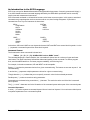
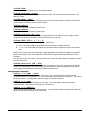
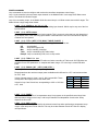
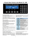
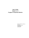
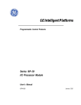
SCPI commands are based on a hierarchical structure, also known as a tree system. In this system, associated
commands are grouped together under a common node or root, thus forming subsystems. A portion the
command tree for a Cryo-con instrument is shown here:
INPut
TEMPerature
UNITs
VARIance
SLOPe
ALARm
NAMe
SYSTem
BEEP
ADRS
LOCKout
LOOP
SETPT
RANGe
RATe
CONFig
SAVE
RESTore
In the above, INPut and LOOP are root keywords whereas UNITs and RATe are second-level keywords. A colon
( : ) separates a command keyword from lower-level keyword.
Command Format
The format used to show commands is shown here:
INPut { A | B | C | D}:ALARm:HIGH <value>;NAMe "name";
The command language is case-insensitive, but commands are shown here as a mixture of upper and lower
case letters. The upper-case letters indicate the abbreviated spelling for the command. For shorter program
lines, send the abbreviated form. For better program readability, send the long form.
For example, in the above statement, INP and INPUT are all acceptable.
Braces ( { } ) enclose the parameter choices for a given command string. The braces are not sent as part of the
command string.
A vertical bar ( | ) separates multiple parameter choices for a given command string.
Triangle brackets ( < > ) indicate that you must specify a numeric value for the enclosed parameter.
Double-quote ( " ) marks must enclose string parameters.
Commands are terminated using a semicolon ( ; ) character. The semicolon at the end of the line is assumed
and is optional.
The {}, |, <> and " characters are for the illustration of the command syntax and not part of the command syntax.
Command Separators
A colon ( : ) is used to separate a command keyword from a lower-level keyword. You must insert a blank space
to separate a parameter from a command keyword.
Cryo-con AB015
2
Compound Commands
A semicolon ( ; ) is used as a terminator character that separates commands within the same subsystem. For
example, sending the following command string:
INPut A:UNITs K;TEMPer?;
has the same effect as sending the following two commands:
INPut A:UNITs K;
INPut A:TEMPer?;
If multiple commands address different subsystems, the combination of a semicolon ( ; ) and a colon ( : ) are
used. The semi-colon terminates the previous command and the colon indicates that the next command is in a
different subsystem. For example:
INPut A:TEMPer?;:LOOP 1:SETPt 123.45;
has the effect of sending the following two commands:
INPut A:TEMPer?;
LOOP 1:SETPt 123.45;
Queries
You can query the current value of most parameters by adding a question mark (?) to the command. For
example, the following command set the setpoint on control loop 1 to 123.45:
LOOP 1:SETPt 123.45;
You can change it into a query that reads the setpoint by using the following:
LOOP 1:SETPt?;
The instrument's response will be a numeric string such as: 123.45.
Compound queries are commonly used to save programming steps. For example, the query:
LOOP 1:SETPt?;PGAin?;IGAin?;DGAin?;
reports the loop 1 setpoint, P-gain, I-gain and D-gain. An example response is:
123.45;20.0;60;12.5;
Note that the response is also separated by semicolons.
The representation of the decimal symbol for floating point numbers must be a period, '.', instead of comma, ',' as
customary used in some European countries.
Command Terminators
The termination of a command line is determined by the type of interface being used.
For the RS-232 serial port interface, command lines are terminated with any of the following:
carriage-return ( \n ), line-feed ( \r ) or null ( 0 ).
On the Ethernet LAN and IEEE-488 (GPIB) interfaces, a hardware-handshake is used, so no termination
character is required. If terminators are sent, they are ignored.
Cryo-con AB015
3
SCPI Common Commands
The IEEE-488.2 SCPI standard defines a set of common commands that perform basic functions like reset, selftest and status reporting. Note that they are called common commands because they must be common to all
SCPI compliant instruments, not because they are commonly used.
Common commands always begin with an asterisk (*), are four to five characters in length and may include one
or more parameters. Examples are:
*IDN?
*CLS
*OPC?
SCPI Parameter Types
The SCPI language defines several different data formats to be used in program messages and response
messages.
Numeric Parameters: Commands that require numeric parameters will accept all commonly used decimal
representations of numbers including optional signs, decimal points and scientific notation.
Enumeration Parameters: These are used to set values that have a limited number of choices. Query
responses will always return an enumeration parameter in upper-case letters. Some examples of commands
with enumeration parameters are:
INPut {A | B | C | D}:UNITs {K | C | F | S}
LOOP { 1 | 2}:TYPe
{ OFF | MAN | PID | TABLE | RAMPP}
String Parameters: String parameters can be up to 15 characters in length and can contain any ASCII
characters excluding the double-quote ( " ). String parameters must be enclosed in double-quotes ( " ). For
example:
CONFig 4:NAMe "Cold Plate"
Cryo-con AB015
4
Commonly Used Commands.
A complete summary of remote commands is given in the User's Manual chapter titled "Remote Command
Summary". The manual also has complete descriptions of all remote commands. This section is intended to
show a few of the more commonly used commands.
iNOTE: Remote commands are not case sensitive.
Function
Command
Comment
Instrument Identification
Read the instrument identification string
*idn?
Returns the instrument identification string in IEEE-488.2 format. For
example:"Cryo-con,Model 32,204683,2.41" identifies the
manufacturer followed by the model name, serial number and
firmware revision code.
Input Channel Commands
Parameter for the input is A, B, C or D corresponding to inputs A, B, C or D.
Read the temperature on input channel B
input? b
Temperature is returned in the current display units. Format is a
numeric string. For example: 123.4567
Set the temperature units on input channel A
to Kelvin.
input a:units k
Choices are K- Kelvin, C- Celsius, F- Fahrenheit and S- native
sensor units (Volts or Ohms).
Read the temperature units on channel B
input b:units?
Return is: K, C, F or S.
Disengage all control loops.
stop
Both control loops are stopped.
Engage all control Loops.
control
Starts both control loops
Ask if control loops are on or off.
control?
Return is ON or OFF
Control Loop Start/Stop commands
LOOP Commands. Configure control loop outputs.
Parameter is 1 or 2 corresponding to Loop 1 or Loop 2.
Set the setpoint for control loop 1
loop 1:setpt 1234.5
Sets the loop 1 setpoint to 1234.5. Units are taken from the
controlling input channel.
Read the setpoint for control loop 1
loop 1:setpt?
Reads the loop 1 setpoint as a numeric string.
Set the controlling source input for loop 1
loop 1:source a
Sets the Loop 1 controlling source to input channel A. Choices are
any input channel.
Set the loop 2 P gain term for PID control.
loop 2:pgain 123.5
P gain is unit-less.
Set the loop 1 I gain term.
loop 1:igain 66.1
I gain has units of seconds.
Set the loop 2 D gain term.
loop 2:dgain 10.22
D gain has units of inverse-seconds.
Set the heater range for loop 1
loop 1:range hi
Choices are hi- high, mid- medium and low- low.
Read the loop 1 heater range
loop 1:range?
Reports HI, MID or LOW
Read the control mode for loop 1
loop 1:type?
Returns the control loop type. Choices are: OFF, MAN, PID, TABLE
or RAMPP.
Set the control mode for loop 2
loop 2:type rampp
Choices are OFF, PID, MAN, TABLE and RAMPP
Set the output power level for manual control.
loop 1:pman 25
Sets the power output of loop 1 to 25% of full scale when the loop is
in the manual output mode.
Read the current output power level
loop 2:htrread?
Reports the current output power as a percentage of full scale.
Cryo-con AB015
5
Debugging Tips
1. To view the last command that the instrument received and the last response it generated, press the
System key and then select the Network Configuration Menu. The last two lines of this menu show > and
< characters. These two lines show the last command received by the instrument and the last response
generated.
2. All commands written to the instrument must be terminated by a \n. Nothing will be parsed until a
terminator is received. All \r characters are ignored. Command and response strings are limited to 80
characters.
3. Commands and queries written to the instrument always generate a response. The user should follow
every data write with a data read operation. A data read completion indicates that the instrument has
completed processing and is ready for more commands. The minimum response is a \n character. If a
syntax error is detected, the instrument will respond with a NAK\n sequence.
4. Commands are parsed left to right. If a syntax error is detected, all commands preceding the error are
executed. It is often easiest to test commands by using the Cryo-con utility software. Run the program,
connect to the instrument and use the Interact mode to send commands and view the response.
5. Commands written to the instrument are case-insensitive but the instrument's response is always uppercase. Floating-point values are returned in their full precision. Large values are returned in C language
notation. For example, 1.23 times 10 to the -12th power is returned as 1.23e-12.
6. For ease of software development, keywords in all SCPI commands may be shortened. The short form
of a keyword is the first four characters of the word, except if the last character is a vowel. If so, the
truncated form is the first three characters of the word. Some examples are: inp for input, syst for system
alar for alarm etc.
7. It is often easiest to test commands by using the Cryo-con utility software. Run the program, connect to
the instrument and use the Interact function to send commands and view the response. Some
communications programs like Windows Hyperterminal can be used to interact with the instrument via
the TCP or serial ports. Both TCP and UDP commands may be used with the TCPclient.exe or
UDPclient.exe Windows program included with Application Brief AB-09.
Cryo-con AB015
6
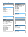
Remote Command Tree
Control Loop Start/Stop commands
Loop Commands
STOP
CONTrol
CONTrol?
LOOP {1| 2}:SOURce {A | B | C | D}
LOOP {1| 2}:SETPt <setpt>
LOOP {1| 2}:TYPe { OFF | PID | MAN | TABLE | RAMPP }
LOOP {1| 2}:TABelix <ix>
LOOP {1| 2}:RANGe { HI | MID | LOW | MIN }
LOOP {1| 2}:RAMP?
LOOP {1| 2}:RATe <rate>
LOOP {1| 2}:PGAin <gain>
LOOP {1| 2}:IGAin <gain>
LOOP {1| 2}:DGAin <gain>
LOOP {1| 2}:PMAnual <pman>
LOOP {1| 2}:OUTPwr?
LOOP {1| 2}:HTRRead?
LOOP {1| 2}:HTRHst?
LOOP {1| 2}:LOAD {50 | 25}
LOOP {1| 2}:MAXPwr <maxpwr>
LOOP {1| 2}:MAXSet <maxset>
SYSTEM commands
SYSTem:LOCKout {ON | OFF}
SYSTem:NVSave
SYSTem:REMLed {ON | OFF}
SYSTem:BEEP <seconds>
SYSTem:DISTc {0.5 | 1 | 2 | 4 | 8 | 16 | 32 | 64}
SYSTem:ADRS <address>
SYSTem:RESeed
SYSTem:HOMe
SYSTem:SYNCtaps <taps>
SYSTEM:NAME "name"
SYSTem:HWRev?
SYSTem:FWREV?
SYSTem:LINefreq {60 | 50}
SYSTem:DRES {FULL | 1 | 2 | 3}
SYSTem:PUControl {ON | OFF}
OVERTEMP commands
OVERtemp:ENABle {ON | OFF}
OVERtemp:SOURce {A | B | C | D}
OVERtemp:TEMPerature <temp>
Configuration Commands
CONFig <ix>:NAMe "name"
CONFig <ix>:SAVe
CONFig <ix>:RESTore
Input Commands
INPut? {A | B | C | D} or INPut {A | B | C | D}:TEMPerature?
INPut {A | B | C | D}:UNITs {K | C | F | S}
INPut {A | B | C | D}:NAMe “Instrument Name”
INPut {A | B | C | D}:SENPr?
INPut {A | B | C | D}:VBIas {1.0MV | 10MV}
INPut {A | B | C | D}:BRANge {Auto | 1.0K | 10K | 100K}
INPut {A | B | C | D}:EXCite {AC | DC}
INPut {A | B | C | D}:ISENix <ix>
INPut {A | B | C | D}:USENix <ix>
INPut {A | B | C | D}:ALARm?
INPut { A | B | C | D }:ALARm:HIGHest <setpt>
INPut { A | B | C | D }:ALARm:LOWEst <setpt>
INPut { A | B | C | D }:ALARm:HIENa { YES | NO }
INPut { A | B | C | D }:ALARm:LOENa { YES | NO }
INPut { A | B | C | D }:Clear
INPut { A | B | C | D }:LTEna { YES | NO }
INPut { A | B | C | D }:AUDio { YES | NO }
INPut { A | B | C | D }:MINimum?
INPut { A | B | C | D }:MAXimum?
INPut { A | B | C | D }:VARiance?
INPut { A | B | C | D }:SLOpe?
INPut { A | B | C | D }:OFFSet?
INPut:STAts:TIMe?
INPut:STAts:RESet
Sensor Calibration Curve Commands
CALcur <num>
IEEE Common Commands
*CLS
*ESE
*ESR
*OPC
*IDN?
*RST
*SRE
*STB
Relay Commands
RELays? {0 | 1}
RELays {0 | 1} :SOURce {A | B | C | D}
RELays {0 | 1} :HIGHest <setpt>
RELays {0 | 1} :LOWEST <setpt>
RELays {0 | 1} :HIENa { YES | NO }
RELays {0 | 1} :LOENa { YES | NO }
PID Table Commands
PIDTable <num>:NAMe “Name String”
PIDTable <num>:NENTry?
PIDTable <num>
Cryo-con AB015
7
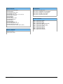
System Commands
Mail Commands
SYSTem:LOCKout {ON | OFF}
SYSTem:NVSave
SYSTem:REMLed {ON | OFF}
SYSTem:BEEP <seconds>
SYSTem:DISTc {0.5 | 1 | 2 | 4 | 8 | 16 | 32 | 64}
SYSTem:ADRes <address>
SYSTem:RESeed
SYSTem:HOMe
SYSTem:SYNCtaps <taps>
SYSTEM:NAME "name"
SYSTem:HWRev?
SYSTem:FWREV?
SYSTem:LINefreq {60 | 50}
SYSTem:DRES {FULL | 1 | 2 | 3}
SYSTem:PUControl {ON | OFF}
SYSTem:BAUD {9600 | 19200 | 38400 | 57200}
MAIL {A | B | C | D} :ADDR “IPA”
MAIL {A | B | C | D}:FROM ”from e-mail address”
MAIL {A | B | C | D}:DEST “to e-mail address”
MAIL {A | B | C | D}:PORT <port number>
MAIL {A | B | C | D}:STATE {ON | OFF}
Network Commands
Autotune Commands
LOOP
LOOP
LOOP
LOOP
LOOP
LOOP
LOOP
LOOP
LOOP
LOOP
{1| 2}:AUTotune:STARt
{1| 2}:AUTotune:EXIT
{1| 2}:AUTotune:SAVE
{1| 2}:AUTotune:MODe {P | PI | PID}
{1| 2}:AUTotune:DELTap <num>
{1| 2}:AUTotune:TIMeout <num>
{1| 2}:AUTotune:AUTop?
{1| 2}:AUTotune:AUToi?
{1| 2}:AUTotune:AUTod?
{1| 2}:AUTotune:STATus?
NETWork:IPADdress
NETWork:MACaddress
Cryo-con AB015
8
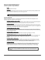
Remote Command Descriptions
Control Loop Start / Stop Commands
STOP
Disengage both control loops.
CONTrol
The control command will cause the instrument to enter the control mode by activating enabled control
loops. To disable an individual loop, set its control type to OFF.
i Note: To disengage temperature control, use the STOP command.
System Commands.
System commands are a group of commands associated with the overall status and configuration of the
instrument rather than a specific internal subsystem.
SYSTem:LOCKout {ON | OFF}
Sets or queries the remote lockout status indicator. Used to enable or lock-out the front panel keypad of
the instrument, thereby allowing or preventing keypad entry during remote operation.
SYSTem:NVSave
Save NV RAM to Flash. This saves the entire instrument configuration to flash memory so that it will be
restored on the next power-up. Generally only used in environments where AC power is not toggled from
the front panel. This includes remote and rack-mount applications.
SYSTem:REMLed {ON | OFF}
Sets or queries the remote LED status indicator on the instrument's front panel. Note that the Remote
LED is automatically handled by the GPIB interface but must optionally be turned on and off when using
the LAN or RS-232 interface.
SYSTem:BEEP <seconds>
Asserts the audible alarm for a specified number of seconds. Command only, no query.
SYSTem:DISTc {0.5 | 1 | 2 | 4 | 8 | 16 | 32 | 64}
Set or query the display filter time constant. The display filter is time-constant filter that is applied to all
reported or displayed temperature data. Available time constants are 0.5, 1, 2, 4, 8, 16, 32 or 64
Seconds.
SYSTem:ADRS <address>
Selects the address that the IEEE-488.2 (GPIB) remote interface will use. The address is a numeric
value between 1 and 31 with a factory default of 12. The addresses assigned to instruments must be
unique on each GPIB bus structure. This command has no effect on other interfaces.
SYSTem:RESeed
Re-seeds the input channel’s averaging filter, allowing the reading to settle significantly faster. The
display filter may have filter time-constants that are very long. The RESEED command inserts the
current instantaneous temperature value into the filter history, thereby allowing it to settle rapidly.
i Note: The RESEED command is useful in systems where a computer is waiting for a
reading to settle. Issuing the RESEED command will reduce the required settling time of
the reading.
Cryo-con AB015
9
SYSTem:HOMe
Causes the front panel display to go to the Operate Screen.
SYSTem:SYNCtaps <taps>
Sets or queries the number of taps in the synchronous filter. This is an advanced setup function. The
default is 7 taps.
SYSTEM:NAME "name"
The controller contains a unit name string that may be set or queried using this command. This can be
used to assign a descriptive name to the instrument.
SYSTem:HWRev?
Queries the instrument’s hardware revision level.
SYSTem:FWREV?
Queries the instrument’s firmware revision level.
SYSTem:LINefreq {60 | 50}
Sets or queries the AC Power Line frequency setting which may be either 50 or 60 for 50Hz or 60Hz.
Command only affects the operation of the synchronous cryo-cooler filter.
SYSTem:DRES {FULL | 1 | 2 | 3}
Sets or queries the controller's display resolution. Choices are:
●
FULL: The VFD will display temperature with the maximum possible resolution.
●
1, 2 or 3: The VFD display will display the specified number of digits to the right of the decimal
point.
NOTE: This command only sets the number of digits displayed on the front panel display. It does NOT
affect the internal accuracy of the instrument or the format of measurements reported on the remote
interfaces.
The main use for this command is to eliminate the flicker in low order digits when the controller is used in
a noisy environment.
SYSTem:PUControl {ON | OFF}
Sets or queries the controller's power up in control mode setting. Power-up in control mode causes the
controller to automatically enter control mode 10 seconds after AC power is applied. Exercise caution
when using this command as it can have unintended consequences.
Configuration Commands
CONFig <ix>:NAMe "name"
Instrument setups can be named for user convenience. This command sets and queries the user
configuration names. The parameter <ix> is the configuration number, which is 0 through 5. The second
parameter, "name", is a string with a maximum length of 15 ASCII characters.
CONFig <ix>:SAVe
Saves an the current instrument setup to a user setup. <ix> is the index number of the desired
instrument setup. Values may be 0 through 5. Command only.
CONFig <ix>:RESTore
Restores a previously stored user instrument setup. <ix> is the index number of the desired instrument
setup. Values may be 0 through 5. Command only.
Cryo-con AB015
10
Input Commands
The INPUT group of commands are associated with the configuration and status of the four input channels.
Parameter references to the input channels may be:
•
•
•
Numeric ranging in value from zero to two.
Channel ID tags including CHA or CHB.
Alphabetic including A or B.
INPut? {A | B | C | D} or INPut {A | B | C | D}:TEMPerature?
The INPUT query reports the current temperature reading on any of the input channels. Temperature is
filtered by the display time constant filter and reported in display units. Query only.
INPut {A | B | C | D}:UNITs {K | C | F | S}
Sets or queries the display units of temperature used by the specified input channel. Units may be K for
Kelvin, C for Celsius, F for Fahrenheit or S for primitive sensor units. In the case of sensor units, the
instrument will determine if the actual units are Volts or Ohms based on the actual sensor type.
INPut {A | B | C | D}:SENPr?
The INPUT:SENPR query reports the reading on a selected input channel. For diode sensors, the
reading is in Volts while resistor sensors are reported in Ohms. The reading is not filtered by the display
time-constant filter. However, the synchronous input filter has been applied. Query only.
INPut {A | B | C | D}:VBIas {100MV | 10MV | 1.0MV | 100UV}
Sets or queries the constant-voltage mode voltage used on the specified input channel. This value only
applies to sensors that use constant-voltage excitation. They are indicated by a sensor type of ACR. If
this query is used with a sensor type other than ACR, it will always return N/A for not applicable.
Choices for bias voltages are:
100MV - 100milliVolt.
10MV - 10milliVolt.
1.0MV - 1.0milliVolt
100UV - 100microVolt.
INPut {A | B | C | D}:ISENix <ix>
Sets or queries the sensor index number assigned to an input channel for FACTORY installed sensors.
For user installed sensors, use to the USENIX command below.
A sensor index, <ix>, is taken from a table. A sensor index of zero indicates that there is no sensor
connected. Refer to Appendix A in the User's Manual for the sensor index table and a complete
description of sensors and indexing.
i Note: The use of the ISENIX command to assign a factory-installed sensor and the
USENIX command to assign a user sensor are preferred to the use of the obsolete
SENIX command.
The SENTYPE command may be used to query the name of a factory-installed sensor at a specific
index.
Cryo-con AB015
11
INPut {A | B | C | D}:USENix <ix>
Sets or queries the sensor index number assigned to an input channel for USER installed sensors. For
factory installed senssors, use the ISENIX command described above. An index number of 0 through 7
indicates user sensor curves 1 through 8.
i Note: The use of the ISENIX command to assign a factory installed sensor and the
USENIX command to assign a user sensor are preferred to the use of the obsolete
SENIX command.
The CALD command may be used to query information about the user installed sensor curves.
INPut {A | B | C | D}:ALARm?
Queries the alarm status of the specified input channel. Status is a two character string where:
-SF
HI
LO
indicates that no alarms are asserted
indicates a Sensor Fault condition.
indicates a high temperature alarm
indicates a low temperature alarm.
There is a 0.25K hysteresis in the assertion of a high or low temperature alarm condition.
The user selectable display time constant filter is applied to input channel temperature data before alarm
conditions are tested.
INPut { A | B | C | D }:ALARm:HIGHest <setpt>
Sets or queries the temperature setting of the high temperature alarm for the specified input channel.
When this temperature is exceeded, an enabled high temperature alarm condition will be asserted.
Temperature is assumed to be in the display units of the selected input channel. There is a 0.25K
hysteresis in the assertion of a high or low temperature alarm condition.
<setpt> is the alarm setpoint temperature.
INPut { A | B | C | D }:ALARm:LOWEst <setpt>
Sets or queries the temperature setting of the low temperature alarm for the specified input channel.
When the input channel temperature is below this, an enabled low temperature alarm condition will be
asserted.
Temperature is assumed to be in the display units of the selected input channel. There is a 0.25K
hysteresis in the assertion of a high or low temperature alarm condition.
<setpt> is the alarm setpoint temperature.
INPut { A | B | C | D }:ALARm:HIENa { YES | NO }
Sets or queries the high temperature alarm enable for the specified input channel. An alarm must be
enabled before it can be asserted.
INPut { A | B | C | D }:ALARm:LOENa { YES | NO }
Sets or queries the low temperature alarm enable for the specified input channel. An alarm must be
enabled before it can be asserted.
INPut { A | B | C | D }:MINimum?
Queries the minimum temperature that has occurred on an input channel since the STATS:RESET
command was issued.
INPut { A | B | C | D }:MAXimum?
Queries the maximum temperature that has occurred on an input channel since the STATS:RESET
command was issued.
Cryo-con AB015
12
INPut { A | B | C | D }:VARiance?
Queries the temperature variance that has occurred on an input channel since the STATS:RESET
command was issued. Variance is calculated as the Standard Deviation squared.
INPut { A | B | C | D }:SLOpe?
Queries the input channel statistics. SLOPE is the slope of the best fit straight line passing through all
temperature samples that have been collected since the STATS:RESET command was issued. SLOPE
is in units of the input channel display per Minute.
INPut { A | B | C | D }:OFFSet?
Queries the input channel statistics. OFFSET is the offset of the best fit straight line passing through all
temperature samples that have been collected since the STATS:RESET command was issued.
OFFSET is in units of the input channel display.
Input Channel Statistics Commands
Temperature statistics on every enabled input channel are continuously accumulated.
Accumulation is initialized whenever a channel is first enabled, or, when a reset command is received.
The STATs commands include the RESet command and a TIMe command that queries the duration of the
accumulation. Queries of statistical data are made using the INPut commands.
STAts:TIMe?
Queries the time duration over which input channel statistics have been accumulated. Time is reset by
issuing the STAt:RESet command. Query only.
STAts:RESet
Resets the accumulation of input channel statistical data.
Cryo-con AB015
13
LOOP commands
Loop commands are used to configure and monitor the controllers temperature control loops.
Loop 1 is the controller’s primary heater output channel. In the Model 42/44 it is a 4-range 50/25-Watt current
source. The Model 24 has three ranges.
Loop 2 is a secondary output. In the Model 42/44 this control loop is a 10-Watt current source with 2 ranges. The
Model 24 has a single range linear heater.
LOOP {1| 2}:SOURce {A | B | C | D}
Sets and queries the selected control loop's controlling input channel. Which may be any one of the four
input channels.
LOOP {1| 2}:SETPt <setpt>
Sets and queries the selected control loop’s setpoint. This is a numeric value that has units determined
by the display units of the controlling input channel. Values above the one set in the maximum setpoint,
or below zero are rejected.
LOOP {1| 2}:TYPe { OFF | PID | MAN | TABLE | RAMPP }
Sets and queries the selected control loop’s control type. Allowed values are:
Off
- loop disabled
PID
- loop control type is PID
Man
- loop is manually controlled
Table - loop is controlled by PID Table lookup.
RampP - loop is controlled by PID, but is in ramp mode.
LOOP {1| 2}:TABelix <ix>
Sets and queries the number of the PID table used when controlling in Table mode. Six PID tables are
available to store PID parameters vs. setpoint and heater range. <ix> is the loop’s control PID table
index.
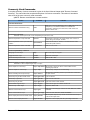
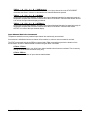
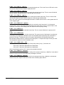
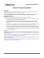
LOOP {1| 2}:RANGe { HI | MID | LOW | MIN }
Sets or queries the control loop's output range.
Range determines the maximum output power available and is different for a 50Ω load resistance than
for a 25Ω load.
Values of heater range for Loop 1 are: Hi, Mid, Low and Min. These
correspond to the output power levels shown here.
Values for loop 2 are Hi and Low, corresponding to 10W or 1.0W into
a 50Ω load.
Range
50Ω Load
25Ω Load
Hi
50W
25W
Mid
5W
2.5W
Low
0.5W
0.25W
Min
50mW
25mW
LOOP {1| 2}:RAMP?
Queries the unit to determine if a temperature ramp is in progress on the specified control loop. Note
that temperature ramps on the Loop 1 and Loop 2 channels are independent of each other. Query
response is ON or OFF.
LOOP {1| 2}:RATe <rate>
Sets and queries the ramp rate used by the selected control loop when performing a temperature ramp.
<rage> is the ramp rate in Units / Minute. This may be a value between 0 and 100. Rate is in display
units per Minute.
Cryo-con AB015
14
LOOP {1| 2}:PGAin <gain>
Sets or queries the selected control loop’s proportional gain term. This is the P term in PID and is a unitless numeric field with values between 0 (off) and 1000.
LOOP {1| 2}:IGAin <gain>
Sets and queries the integrator gain term used by the selected control loop. This is a numeric field with
units of seconds. Allowed values are 0 (off) through 1000 seconds.
LOOP {1| 2}:DGAin <gain>
Sets and queries the differentiator gain term used by the selected control loop. This is a numeric field
with units of inverse seconds. Allowed values are 0 (off) through 1000/Seconds.
Note: Use of the D gain term can add significant noise. It should never be set to a value greater than 1/4
of the integrator gain.
LOOP {1| 2}:PMAnual <pman>
Sets and queries the output power level used by the selected control loop when it is in the manual
control mode. <value> is the desired selected control loop output power. This is a numeric field in units
of percent of full scale. Actual output power will depend on the loop range setting.
LOOP {1| 2}:OUTPwr?
Queries the output power of the selected control loop. This is a numeric field that is a percent of full
scale.
LOOP {1| 2}:HTRRead?
Queries the actual output power of either control loop. The output current of the heaters is continuously
monitored by an independent read-back circuit. The read-back power reported by this command is a
percent of full scale. The absolute value of full scale is determined by the selected heater range.
Note that the read-back value is a percent of full-scale power. To compute the output current, you must
first compute the square-root of the read-back value.
LOOP {1| 2}:LOAD {50 | 25}
Sets or queries the load resistance setting of the primary heater (Loop 1). Selections are:
50 for a 50Ω load and a 50W maximum output power.
25 for a 25Ω load and a 25W maximum output power.
Note: Loop 2 always requires a 50Ω load so this command is ignored.
LOOP {1| 2}:MAXPwr <maxpwr>
Sets or queries the maximum output power setting of the selected control loop. <MaxPwr> is the desired
maximum output power limit expressed as a percentage of full scale.
LOOP {1| 2}:MAXSet <maxset>
Sets or queries the maximum allowed set point for the selected control loop. <MaxSet> is the desired
maximum set point. Setpoint values are in units of the controlling input channel.
Cryo-con AB015
15
OVERTEMP commands
These commands are associated with the heater’s Over Temperature Disconnect (OTD) feature. This is used to
disconnect the heater if a specified temperature is exceeded on any selected input channel.
OVERtemp:ENABle {ON | OFF}
Sets and queries the Over Temperature Disconnect enable. The OTD will not function if disabled.
OVERtemp:SOURce {A | B | C | D}
Sets and queries the input channel that is used as the source for the Over Temperature Disconnect
feature.
OVERtemp:TEMPerature <temp>
Sets and queries the temperature used by the over temperature disconnect feature. Note that this
temperature has the same units of the source input channel.
Cryo-con AB015
16
Sensor Calibration Curve Commands
The CALCUR commands are used to transfer sensor calibration curves between the controller and the host
controller.
Curves are referenced by an index number. In the Model 42/44, there are eight user curves numbered 1 through
8.
The CALCUR data block consists of a header, multiple curve entries and a terminator character.
The header consists of four lines as follows:
Sensor Name:
Sensor Type:
Multiplier:
Units:
Sensor name string, 15 characters max
Enumeration {diode | PT100 | PT1K | PT10K | ACR}
Signed numeric
Units of calibration curve: {OHMS | VOLTS | LOGOHM}
Each entry of a curve contains a sensor reading and the corresponding temperature. Sensor readings are in
units specified by the units of the curve using the CALDATA:UNITS command. These units may be OHMS,
VOLTS or LOGOHM. Temperature is always in Kelvin.
The format of an entry is:
<sensor reading> <Temperature>
Where <sensor reading> is a floating-point sensor reading and <Temperature> is a floating-point temperature in
Kelvin.
Numbers are separated by one or more white spaces.
i NOTE: Using the RS-232 interface, each line must be terminated by a New Line, a
Carriage Return, a Line Feed or a Null character. This character is not used with the
GPIB or LAN interfaces since the end of a line is signaled by the interface itself. Here,
lines are transmitted to the controller by using sequential write commands.
Floating point numbers may be entered with many significant digits. They will be converted to 32 bit floating
point. This supports about six significant digits.
The last entry of a table is indicated by a semicolon ( ; ) character with no values in the numeric fields.
i NOTE: All curves must have a minimum of two entries and a maximum of 200 entries.
Entries may be sent to the controller in any order. The unit will sort the curve in ascending order of sensor
reading before it is copied to Flash RAM. Entries containing invalid numeric fields will be deleted before they are
stored.
Cryo-con AB015
17
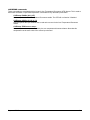
The following is an example of a calibration curve transmitted to the controller via the GPIB interface:
CALCUR 1
Good Diode
Diode
–1.0
volts
0.34295 300.1205
0.32042 273.1512
0.35832 315.0000
1.20000 3.150231
1.05150 8.162345
0.53234 460.1436
;
i Note: Factory installed calibration curves may not be changed or deleted with these
commands.
CALCUR <index>
Sets or queries sensor calibration curve data.
Command Syntax:
CALcur <index>
"sensor name"
{diode | PT100 | PT1K | PT10K | ACR}
<multiplier>
{OHMS | VOLTS | LOGOHM}
<sensor reading 1> <Temperature 1>
<sensor reading 2> <Temperature 2>
•
<sensor reading N> <Temperature N>
;
i Note: A new line (\n) character must be appended to each line when
using the RS-232 serial port. They should not be included when using the
GPIB or LAN interface.
The maximum number of entries in a curve is 200 and the minimum is 2.
<index> is a zero-based numeric index to the user calibration curve list.
<curve name> is a name to be assigned to the calibration curve. It is a minimum of 4 and a
maximum of 15 ASCII characters.
<multiplier> is the temperature coefficient and curve multiplier.
<curve units> is the units of the curve. Choices are OHMS, VOLTS or LOGOHM.
The last entry in a calibration curve must be a single semicolon.
Cryo-con AB015
18
Cryogenic Control Systems, Inc.
PO Box 7012
Rancho Santa Fe, CA 92067-7012
Telephone: 858 756 3900
FAX: 858 759 3515
[email protected]
www.cryocon.com
Updated: 2/12/11
Cryo-con AB015
19