1
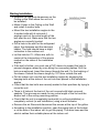
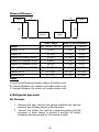
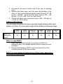
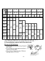
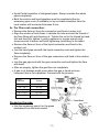
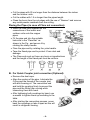
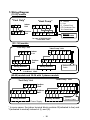
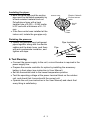
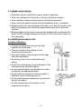
1- Installer Instructions:
•
•
•
•
•
Read this manual carefully to ensure correct installation.
Give the customer full instruction on how to handle the system.
Never share a common power source with other equipment.
Never close the safety breaker until all installation work is complete.
Regarding the link wiring between the indoor unit, and the outdoor unit
and the grounding wire, follow the applicable local code of electrical
facilities.
• Before supplying the power, measure the voltage with a voltmeter and
check that the voltage measured is within ±10% of the value shown on
the nameplate.
2 - I n s ta l l i n g t h e I n d o o r u n i t:
Location Selection:
• Choose a position that assures the best
possible air distribution.
• Choose a position that allows for the
clearance requirements.
• The wall surface is flat enough to allow easy
and safe installation.
• Avoid any raise in the condensate drain
piping.
• Avoid any unnecessary turns and bends in the
interconnecting refrigerant pipes.
• Avoid positions where condensate can easily
be piped to an appropriate drain.
• Avoid positions exposed to direct sunlight or
positions close to heating sources.
• Avoid positions where obstacles may obstruct
free air circulation.
• Avoid positions where the Indoor unit is
exposed to oil vapors.
-1-
Starting Installation:
• Measure the required dimensions on the
Ceiling or the Wall where the unit is to
be installed.
• Make 4 holes in the Ceiling or the Wall
and install 4 anchor bolts.
• Mount the two installation angles to the
4 anchor bolts with 4 nuts and 4
washers and cut the extra length of the
bolt after the nut. Make sure that the two
angles are correctly leveled.
• Drill a hole in the wall for the refrigerant
pipes, the drainpipe and the electrical
cables. The hole should have a slight
inclination to the outdoor unit.
• Let the hole be 70 - 80mm dia. with its
center at the intersection of the arrows
marked on the sides of the installation
angles.
• If the wall is hollow, you must use a PVC sleeve to support the hole to
prevent dangers caused by mice biting the connecting cables. Drill the
hole as mentioned. Insert the sleeve through the wall. Fix the bushing of
the sleeve. Extend the sleeve length by 10-15mm outside the wall.
• Put the indoor unit over the two installation angles by engaging the
hanging bolts at the sides of the unit into their places in the installation
angles.
• Check that the two bolts are securely seated in their positions by trying to
move the unit.
• There is 4 holes at the back of the unit covered with black grooved
gaskets. The grooves are made for any extra length of the nut and the
anchor bolt in the ceiling mounting position.
• Check that the unit is completely horizontal (in ceiling installation) or
completely vertical (in wall installation) using a level indicator.
• Remove the air filters and disconnect the screws at the top of the grilles.
• According to the installation position, open the piping hole at the bottom
or at the side of the indoor unit to get the piping. The drain hose and the
electric cables their suitable places at the indoor unit.
-2-
3- Installing the Outdoor unit:
Location Selection:
[19.7 inch]
min. 500 mm
[39.4 inch]
min 700 mm
[27.6 inch]
min. 200 mm
[7.9 inch]
min. 700 mm
[27.6 inch]
[39.4 inch]
NO !
[19.7 inch]
min. 500 mm
Service area required
[118.1 inch]
min. 3000 mm
[15.7 inch]
min. 400 mm
Air flow direction
All Dim. in m.m.[inch]
-3-
[59.1 inch]
min. 1500 mm
min. 1000 mm
min. 1000 mm
min. 250 mm
[9.8 inch]
• If possible, don’t install the unit where it will be exposed to direct sunlight.
• Don’t install the unit where a strong wind blows or where it is very dusty.
• Take you neighbors into consideration so they are not disturbed by air
blowing into there windows or by noise.
• Flow the dimensions as shown below.
• Don’t set the unit directly on the ground because it will cause trouble.
Distance Difference:
Indoor
(A)
(A)
(B)
Outdoor
(C)
Outdoor
Indoor
Total Length
Max. Level Difference
A + ( B or C ) m (ft)
B m (ft)
C m (ft)
Indoor 12-13
12 (40)
7.5 (25)
6 (20)
Indoor 18
16 (54)
7.5 (25)
6 (20)
Indoor 20/Outdoor 20GA
24 (80)
7.5 (25)
6 (20)
Indoor 20/ Outdoor 20GO
20(66)
7.5 (25)
6 (20)
Indoor 25/ Outdoor 25GA
24 (80)
7.5 (25)
6 (20)
Indoor 25/Outdoor 25GO
24 (80)
7.5 (25)
6 (20)
Indoor 30:36
30 (100)
10 (32)
8.5 (28)
Indoor 48:60
40 (113)
10 (32)
8.5 (28)
Model
Where
A: Horizontal Distance between Indoor & outdoor units.
B: Vertical Distance (for outdoor unit under indoor unit).
C: Vertical Distance (for indoor unit under outdoor unit).
4- Refrigerant pipe work:
Air Vacuum:
1. Remove the cap; connect the gauge manifold and vacuum
pump to the charging valve by service hoses.
2. Vacuum the indoor unit and the connecting pipes until the
pressure in them lowers to below1.5 mmHg (-30 inHg),
keeping vacuum process for 10 minutes at least.
-4-
3. Disconnect the service hoses and fit the cap to charging
valve.
4. Remove the blank caps, and fully open the spindles of the
2way or 3way valve with Hexagonal wrench (torque 70 - 90
kgf.cm = 516.29 - 663.8 Ib-ft) for 2way valve & 100 - 120
kgf.cm = 737.56 - 885.7 Ib-ft) for 3way valve.
5. Tighten the blank cap to specified torque (200 – 250 kgf.cm
= 1475.12 - 1843.9 Ib-ft).
Additional Refrigerant:
The unit design considered the pipes equivalent length between indoor and
outdoor is 4 meter. For more pipes length add the additional following charge.
Additional
Refrigerant
“gm/m”
Indoor
12-13
Indoor
18-20
Indoor 2530-32
Indoor
36
Indoor
48-50
Indoor
60
20
25
30
35
40
45
Note: In case R407C
1. Never add additional charge to increase the R407C of
leakage system, the leakage system must be repair first and
recharge.
2. During initial charging, R407C must be removed from the
charging cylinder in the liquid phase.
R407C is a new refrigerant which prevent Ozone layer destruction.
Selecting the copper pipe
-5-
Equivalent
Length
m
f
t
Model
Name
Indoor
13
1-6
6 - 12
12 - 16
16- 20
20 - 24
24 - 30
3 - 20
20 - 40
40 - 54
54 - 66
66 - 80
80 - 100
S
S
S
S
S
S
L
L
Indoor
36
Indoor
048-5060
L
L
15.9
(5/8”)
15.9
(5/8”)
15.9
(5/8”)
9.5
(3/8”)
Indoor
25*
Indoor
30-032
L
12.7 6.4 12.7
(1/2”) (1/4”) (1/2”)
Indoor
18
Indoor
20*
L
19
(3/4”)
9.5
(3/8”)
19
(3/4”)
19
(3/4”)
22.2
(7/8”)
22.2 12.7 22.2 12.7 28.5
(7/8”) (1/2”) (7/8”) (1/2”) (11/8”)
9.5
19
9.5
19
9.5
(3/8”) (3/4”) (3/8”) (3/4”) (3/8”)
22.2
(7/8”)
12.7
(1/2”)
28.5
(11/8”)
12.7
(1/2”)
22.2
(7/8”)
28.5
(11/8”)
12.7
(1/2”)
22.2
(7/8”)
28.5
(11/8”)
* For Indoor 20/Outdoor 20GO The max. length is 20 meter (66 feet). &
Indoor 25/Outdoor 25GO The max. length is 24 meter (80 feet).
5- Connecting the outdoor unit to the indoor unit
Be sure of the following:
• Avoid excessive interconnecting refrigerant
pipe length.
• Do not bend the copper pipes more than 3
times at the same spot.
• DO not kink or flatten the pipes. Minimum
bending radius is 100 mm.
-6-
12.7
(1/2”)
• Avoid Partial insulation of refrigerant pipes. Always insulate the whole
pipes completely.
• Both the suction and liquid pipelines must be insulated either by
accessory pipe cover (if available) or by a suitable insulation from the
local market with minimum thickness 8 mm.
A- For Flare nut connection:
• Remove the flare nut from the connection end fixed in indoor unit.
• Align the centers of both flares. Lubricate the tube end and the thread of
the flare fitting with anti-freezing oil. Tighten the nut to the thread by hand
first and then fully tighten it using a spanner or regular wrench and
torque wrench to assure sufficient tightening (according to the table).
• Remove the flare nut from of the liquid connection end fixed in the
outdoor unit.
• Join the liquid pipe end with the liquid connection end and tighten the
flare completely.
• Remove the flare nut from of the gas connection end fixed in the outdoor
unit.
• Join the gas pipe end with the gas connection end and tighten the flare
with hand.
• After air purging, tighten the gas flare nut completely.
• A gas or oil leakage might occur when the gas or liquid nuts are
loosened, that is not a problem. Proceed with the process.
Pipes
Diameter
Torque
Mm ( inch )
N.m
6.4 ( 1/4" )
18 – 20
9.5 ( 3/8" )
32 – 35
12.7 ( 1/2" )
52 – 55
15.9 ( 5/8” )
55 – 65
Preparing the pipe:
• Use the accessory pipe kit or the pipes
purchased from the local market.
-7-
• Cut the pipes with 25 cm longer than the distance between the indoor
and the outdoor units.
• Cut the cables with 1.5 m longer than the pipes length.
• Clean the burrs from the cut edges with the use of “Reamer” and remove
any metal powder residuals from the cutting.
Flaring the Pipes (in case of Flare nut connection):
• Insert the flare nuts supplied on the
connections of the indoor and
outdoor units onto the copper
pipes.
• Fit the pipe end into the suitable
hole size in the “Flare Bar” as
shown in the Fig., and secure it by
rotating the clamp handle.
• Flare the pipe end by rotating the yoke handle.
• Tape the flared pipe end to protect it from dust and
damage.
• The Flare end must not have any burrs or imperfections
and the length of the flared part must be uniform.
B- For Quick Coupler joint connection (Optional):
• Remove the dust caps.
• Align the centers of the pipe. Lubricate the
O-ring and the thread of the coupler joint
with anti-freezing oil. The connection end
and hold the coupling firmly to prevent the
pipe and the fitting from moving while
connecting them with hand.
• After tightening both couplings by hand, use
a wrench to tighten them up according to the
table.
• After starting the connection process, never
back the couplings or take it apart as this will
result in refrigerant loosing.
-8-
Checking for Leakage:
Check all connections for leakage by applying soapsuds to them and
inspect carefully any bubbling. Wipe the soapsuds off completely.
Air Purging (for units works with R22):
• This process is required only for the flare nut connections.
• Remove the blind caps from the liquid and gas valves.
• Loosen the liquid valve stem by 1/4 turn, and 5 seconds later tighten it up
swiftly.
• The air will leak from the gas valve with hiss. Be sure that the hissing
continues for 10 seconds.
• As soon as the hissing stops, tighten the gas flare nut firmly with a
wrench.
• If the hissing stops before 10 seconds, perform the process again.
6- Drainage Pipe Work
• Install the drain hose end to the indoor unit and let it go along with the
refrigerant pipes to the outdoor unit as in the drawing.
• Open the front air grill and pour some water on the evaporator.
• Ensure if water flows through drain hose without any leakage.
-9-
7- Wiring Diagram
(12:25) models
"Cool Only"
"Heat Pump"
N C
Indoor
Unit
N
C W CF
N L C
Outdoor
Unit
N
L
C
N Neutral
L Live
C Control Cool
CF Condenser Fan
W Control Heat
W CF
Defrost
Sensor Cable
In case of 208-230/1/60:
L1≡ N and L2≡L
(20 : 36) models
"Cool Only" Unit
"Heat Pump" Unit
Indoor
Unit
B Y C
N
Outdoor
Unit
N L B Y C
Safety Breaker
L
B
Y
C
W CF
B
Y
C
W
CF
Defrost Sensor
Cable
Safety Breaker
In case of 208-230/1/60:
L1≡ N and L2≡L
(48-60) models and 30:36 with 3 phases models
"Heat Pump" Unit
"Cool Only" Unit
B Y
N
L1 L2 L3 B
Y
C
C
Indoor
Unit
Outdoor
Unit
Safety Breaker
N
B
Y
C W CF
L1 L2 L3 B
Y
C
Safety Breaker
W CF
Defrost
Sensor Cable
Power Supply
* In some cases, the indoor terminal block contains: B(indicated to live) and
Y(indicated to neutral) instead of (L) and (N).
- 10
Insulating the pipes:
• Both the liquid pipe and the suction
pipe must be insulated separately by
a Heat resistant material such as
Polyethylene foam with a heat
transfer rate of 0.035 – 0.045 kcal/m
h OC and with a thickness of 8 - 10
mm.
• If the flow control was installed at the
indoor unit, isolate the gas pipe only.
Finishing the process:
• Gather the gas and liquid refrigerant
pipes together along with the electric
cables and the drain hose, seal them
with anti-condensate insulation, and
tighten with tape.
Suction Line
Electric Cables &
De-frost sensor
cable.
Liquid
Line
Drain
Hose
Pipe Insulation
Pipe
Adhesive
tape
8- Test Running
• Connect the power supply to the unit; a circuit breaker is required in the
power supply line.
• Prepare the remote controller for option by installing the accessory
battery in their place (see instruction in User Manual).
• Set the thermostat knob to the lowest temperature position.
• Test the operating voltage at the power terminal block on the outdoor
unit, and check that it accords with the correct volt.
• Operate the unit (see instruction in the User Manual) and check that
every thing is satisfactory.
-1 1