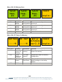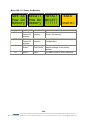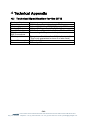
1
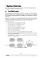
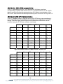
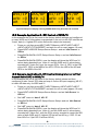
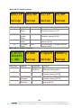
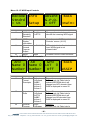
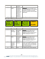
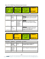
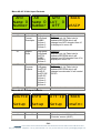
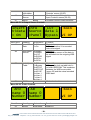
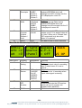
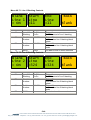
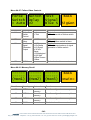
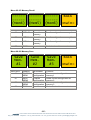
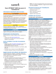
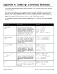
eyeheight
DT-2
video index and WSS transcoder
user manual
Table of Contents
1 System Overview ...............................................................................................4
1.1
The DT-2 Product ...................................................................................4
1.2
Fundamentals of Operation.....................................................................5
1.2.1 Available AR & AFD Source Formats ..................................................5
1.2.2 Available AFD & AR Destination Formats............................................5
1.2.3 VI & WSS Additional Data Handling.....................................................5
1.2.4 Failsafe Features .................................................................................5
1.2.5 Native AR & AFD representation .........................................................6
1.2.6 User AR & AFD representation ............................................................6
1.2.7 GPIs – Latched Vs Linear ....................................................................7
1.2.8 Built-In Mapping Tables .......................................................................7
1.3
Applications for the DT-2 ........................................................................8
1.3.1 Example Application 1 - Manual Control of WSS/VI ............................8
1.3.2 Example Application 2 - GPI Control of WSS/VI ..................................9
1.3.3 Example Application 3 - GPI Control (Using Internal LUT) of Aspect
Ratio (AR) in WSS/VI....................................................................................9
1.3.4 Settings for Example Application-Using WSS to control GPI Outputs
Using Internal LUT ......................................................................................10
1.4
Associated Equipment for the DT-2 ......................................................10
1.4.1 Chassis ..............................................................................................10
1.4.2 Control Equipment for the DT-2 .........................................................10
2 Installation ........................................................................................................12
2.1
Installation of the DT-2 product .............................................................12
3 Operation .........................................................................................................14
3.1
Menu Control of the DT-2......................................................................14
4 Technical Appendix ..........................................................................................30
4.1
Technical Specification for the DT-2 .....................................................30
-2eyeheight Unit 34 Park House Watford Business Park Greenhill Crescent Watford Herts GB WD18 8PH
Reg. No. 2855535 Telephone: +44 (0) 1923 256 000 Fax: +44 (0) 1923 256 100 email: [email protected]
Table of Figures
Figure 1 DT-2 System Block Diagram ...................................................................4
Figure 2 Text Representations of AR for Built-In AR Name Sets ..........................6
Figure 3 Text Representations of AFD for Built-In AFD Name Sets ......................7
Figure 4 Mapping Table Configuration ..................................................................7
Figure 5 Example of display showing WSS/VI data being decoded and encoded 9
Figure 1-6 flexiPanel (FP-9) ................................................................................11
Figure 7 deskPanel (FP-10) ................................................................................11
Figure 8 DT-2 Connections .................................................................................12
-3eyeheight Unit 34 Park House Watford Business Park Greenhill Crescent Watford Herts GB WD18 8PH
Reg. No. 2855535 Telephone: +44 (0) 1923 256 000 Fax: +44 (0) 1923 256 100 email: [email protected]
1 System Overview
This manual describes the function of the DT-2. This unit decodes and encodes
Video Index and WSS in an SDI video signal.
1.1
The DT-2 Product
This manual describes the function of the DT-2. This unit is a Video Index and
WSS transcoder. It is a comprehensive answer to Video Index (VI) and Wide
Screen Signalling (WSS) encoding and decoding. Full functionality of encoding
and decoding on one card allows more flexibility. All known data formats are
supported.
The unit is an upgrade of the Eyeheight ADP-1000 uniBox and has been
designed to be move user configurable as well as including new features such as
user configurable blanking generators and a flexible Loss-ident system.
The main features are :•
Encodes VI (line11) and WSS (Line 23) data.
•
Encodes Data from GPI/RS232/Fixed input.
•
Converts WSS to VI or VI to WSS.
•
Decodes VI (line11) and WSS (line 23) data.
•
Decodes data to GPI/RS232/Panel Display
•
WSS to UK or ETSI Standards.
•
VI to Class 1 and Class 2 data with optional Class 3 (user data).
•
One ½ line and two configurable blanking areas enabled data in any areas
of the screen to be blanked.
•
Configurable Loss Ident provides a test signal background with optional
user Ident if video input fails
Figure 1 DT-2 System Block Diagram
-4eyeheight Unit 34 Park House Watford Business Park Greenhill Crescent Watford Herts GB WD18 8PH
Reg. No. 2855535 Telephone: +44 (0) 1923 256 000 Fax: +44 (0) 1923 256 100 email: [email protected]
1.2 Fundamentals of Operation
The DT-2 unit is primarily a data trans-coder taking AFD & AR data from one
source format and trans-coding it to a destination format. Each destination format
can be separately configured and all destinations can be active simultaneously.
1.2.1 Available AR & AFD Source Formats
Wide-Screen Signalling (WSS) extraction in either ETSI format (AR info only) or
UK Line 23 format (AR & AFD info)
Video Index (VI) extraction of Class 1.1, first Octet (AR & AFD info)
GPI Input either 7 bit latched or 8 bit linear interface (AR and/or AFD info
depending on GPI coding selection)
RS-232 serial communications (AR & AFD info)
User panel configuration (AR & AFD info)
1.2.2 Available AFD & AR Destination Formats
Wide-Screen Signalling (WSS) insertion in either ETSI format (AR info only) or
UK Line 23 (UK_L23) format (AR & AFD info)
Video Index (VI) insertion Class 1.1, first Octet (AR & AFD info)
GPI’s 8 bit linear interface (AR and or AFD info depending on GPI coding
selection)
RS-232 serial communications (AR & AFD info)
User panel display (independent AR & AFD info for VI and WSS inserters)
1.2.3 VI & WSS Additional Data Handling
In addition to its primary role as an AR & AFD trans-coder the DT-2 also allows
control over all of the extra data available in the ETSI WSS, UK_L23 WSS and VI
signals when using identical source and destination formats. The DT-2 Setup
software and DG-9 dongle are required to allow extra data to passed or forced to
known values on a bit by bit basis. By default all extraneous data is passed as is
if present. When using different source and destination formats all extra data in
the destination format is forced to ‘0’.
1.2.4 Failsafe Features
The DT-2 also incorporates a number of failsafe features that include an
internally generated ident signal in the event of a loss of input video and a fallback source option for each destination format in the event that no data is
present on the selected primary source.
-5eyeheight Unit 34 Park House Watford Business Park Greenhill Crescent Watford Herts GB WD18 8PH
Reg. No. 2855535 Telephone: +44 (0) 1923 256 000 Fax: +44 (0) 1923 256 100 email: [email protected]
1.2.5 Native AR & AFD representation
The DT-2 represents the AR & AFD data as two 3 bit binary numbers
corresponding to AR & AFD values from 0-7. In situations where the AR & AFD
data is combined the data is represented as a 6 bit binary concatenation of the
AR & AFD data with the AR data represented by bits 5-3 and the AFD by bits 2-0.
1.2.6 User AR & AFD representation
The DT-2 enables users to map the native AR & AFD binary representations to
more meaningful text representations by selecting sets of AR names and AFD
names. The name sets and the names of the name sets themselves can be
modified using the DT-2 Setup software and dongle.
Number
Defn’d
ETSI
BBC
User 1
User 2
AR=000
AR =0
NoInfo
4:3
AR =8
AR =0
AR =0
AR=001
AR =1
4x3 –5
14:9 C
AR =9
AR =1
AR =1
AR=010
AR =2
4x3 –6
14:9 T
AR =10
AR =2
AR =2
AR=011
AR =3
Reserv
16:9 C
AR =11
AR =3
AR =3
AR=100
AR =4
Reserv
16:9 T
AR =12
AR =4
AR =4
AR=101
AR =5
16x9-5
>16:9C
AR =13
AR =5
AR =5
AR=110
AR =6
16x9-6
4:3SPC
AR =14
AR =6
AR =6
AR=111
AR =7
Reserv
16:9An
AR =15
AR =7
AR =7
Figure 2 Text Representations of AR for Built-In AR Name Sets
Number
Defn’d
BBC
User 1
User 2
User 3
AFD=000 AFD =0
Raster
FAULT
AFD =0
AFD =0
AFD =0
AFD=001 AFD =1
4x3
12F12C
AFD =1
AFD =1
AFD =1
AFD=010 AFD =2
16x9
16F16A
AFD =2
AFD =2
AFD =2
AFD=011 AFD =3
14x9
14P16B
AFD =3
AFD =3
AFD =3
AFD=100 AFD =4
Reserv
FAULT
AFD =4
AFD =4
AFD =4
AFD=101 AFD =5
4x3STP
14L12B
AFD =5
AFD =5
AFD =5
AFD=110 AFD =6
16x9SP
16F16B
AFD =6
AFD =6
AFD =6
AFD=111 AFD =7
Reserv
16F16C
AFD =7
AFD =7
AFD =7
-6eyeheight Unit 34 Park House Watford Business Park Greenhill Crescent Watford Herts GB WD18 8PH
Reg. No. 2855535 Telephone: +44 (0) 1923 256 000 Fax: +44 (0) 1923 256 100 email: [email protected]
Figure 3 Text Representations of AFD for Built-In AFD Name Sets
N.B. changing the AR or AFD names does not alter the underlying binary
representation or the data handled by the destination format only the way that
data is represented to the user via the panel.
1.2.7 GPIs – Latched Vs Linear
The GPI inputs can be configured to operate in either 8 bit linear mode where the
bits represent an 8 bit binary encoded value with GPI1 = bit 0 and GPI8 = bit 7 or
a 7 bit latched mode where GPI1-7 represent a 7 bit binary encoded value but the
value is latched into the DT-2 on the rising edge of GPI8 which does not
contribute to the binary encoded value.
1.2.8 Built-In Mapping Tables
The DT-2 uses mapping tables to control how source data is transformed to
destination data. The source data essentially provides an address to mapping
table and the data stored at that location in the mapping table is used as data by
the destination.
Figure 4 Mapping Table Configuration
The DT-2 has the following 6 built-in mapping tables:-
OFF
All source data maps to all ‘0’s
BYPASS
Source data is unchanged by the mapping table
AFD IP
Designed to allow the GPI inputs to provide the AFD data as highest-bit-takesprecedence i.e. if the highest GPI input set is GPI4(bit 3 as GPI’s number 1 to 8)
then the AFD is taken to be 4 (“100”) irrespective of the lower GPI inputs. The AR
is always taken as 0 (“000”).
AR IP
Designed to allow the GPI inputs to provide the AR data as highest-bit-takesprecedence i.e. if the highest GPI input set is GPI4(bit 3 as GPI’s number 1-8)
-7eyeheight Unit 34 Park House Watford Business Park Greenhill Crescent Watford Herts GB WD18 8PH
Reg. No. 2855535 Telephone: +44 (0) 1923 256 000 Fax: +44 (0) 1923 256 100 email: [email protected]
then the AR is taken to be 4 (“100”) irrespective of the lower GPI inputs. The AFD
is always taken as 0 (“000”).
AFD OP
Designed to allow the GPI outputs to represent the AFD data by setting the
appropriate GPI and clearing all others i.e. if the AFD is 6 (“110”) then GPI6 will
be set and all others cleared.
AR OP
Designed to allow the GPI outputs to represent the AR data by setting the
appropriate GPI and clearing all others i.e. if the AR is 6 (“110”) then GPI6 will be
set and all others cleared.
User Mapping Tables
In addition to the 6 built-in mapping tables the DT-2 provides 4 user mapping
tables which can be named and edited using the DT-2 Setup software which can
be downloaded from www.eyeheight.com and DG-9 dongle. By default these 4
tables are the same as the BYPASS built-in table.
1.3 Applications for the DT-2
Applications for the DT-2 include the following:•
Re-mapping between VI, WSS UK and WSS ETSI information
•
Auto-inserting different values of VI/WSS via GPI inputs
•
Reconstructing and inserting VI/WSS when input VI/WSS is corrupt
•
Interfacing between a video input with VI/WSS and other equipment
(ARC’s, Keyers, etc) via the GPI outputs
1.3.1 Example Application 1 - Manual Control of WSS/VI
In this example the unit is first reset to the factory default settings and then
configured to insert WSS and VI data set via the front panel.
•
Power on unit then press NEXT>NEXT>Memory>NEXT>NEXT>NEXT
>NEXT>NEXT>TOTAL!RESET! and wait for unit to reset (approx 10 secs)
•
Press NEXT>WSS/OP Setup>Source Setup> and set ‘Info Source’ to
‘Panel’
•
Press BACK>Alt-Ip Setup> and set WPn to desired WSS value to be
encoded
•
Press BACK>BACK>VI/OP Setup>Source Setup> and set ‘Info Source’
to ‘Panel’
•
Press BACK>Alt-Ip> and set ‘VPn’ to desired VI value to be encoded
•
Press BACK>BACK>PREV> now the display will show the WSS and VI
values being decoded from ‘Video In’ and the WSS and VI values being
encoded into ‘Video Out’ from the ‘Panel’ values set above
-8-
eyeheight Unit 34 Park House Watford Business Park Greenhill Crescent Watford Herts GB WD18 8PH
Reg. No. 2855535 Telephone: +44 (0) 1923 256 000 Fax: +44 (0) 1923 256 100 email: [email protected]
WSS/IP WSS/OP VI/IP
VI/OP
AFD =0 AFD =2 AFD =4 AFD =6
AR =1 AR =3 AR =5 AR =7
Figure 5 Example of display showing WSS/VI data being decoded and encoded
1.3.2 Example Application 2 - GPI Control of WSS/VI
In this example the unit is first reset to the factory default settings and configured
to insert WSS and VI information as presented to the unit via the GPI interface as
“linear” data (i.e. highest GPI active defines the data to be inserted).
•
Power on unit then press NEXT>NEXT>Memory>NEXT>NEXT>NEXT
>NEXT>NEXT>TOTAL!RESET! and wait for unit to reset (approx 10 secs)
•
Press NEXT>WSS/OP Setup>Source Setup > and set ‘Info Source’ to
‘GPILn’
•
Press BACK>BACK>VI/OP Setup>Source Setup > and set ‘Info Source’
to ‘GPILn’
•
Press BACK>BACK>PREV> now the display will show the WSS and VI
values being decoded from ‘Video In’ and the WSS and VI values being
encoded into ‘Video Out’ from the current GPI’s 1 thru 6. GPI1 is the LSB
of the AFD, GPI3 is the MSB of the AFD. GPI4 is the LSB of the AR and
GPI6 is the MSB of the AR.
1.3.3 Example Application 3 - GPI Control (Using Internal LUT) of
Aspect Ratio (AR) in WSS/VI
In this example the unit is first reset to the factory default values and then
configured to take “linear” GPI data and map it via the AR input mapping (AR IP)
to insert AR data only for WSS and VI
•
Power on unit then press NEXT>NEXT>Memory>NEXT>NEXT>NEXT
>NEXT>NEXT>TOTAL!RESET! and wait for unit to reset (approx 10 secs)
•
Press NEXT>WSS/OP Setup>Source Setup> and set ‘Info Source’ to
‘GPI Ln’
•
Set ‘LUT’ menu to ‘data 3 AR IP’
•
Press BACK>BACK>VI/OP Setup>Source Setup> and set ‘Info Source’
to ‘GPI Ln’
•
Set ‘LUT’ menu to ‘data 3 AR IP’
•
Press BACK>BACK>PREV> now the display will show the WSS and VI
values being decoded from ‘Video In’ and the WSS and VI values being
encoded into ‘Video Out’, with the GPI’s priority encoded to control the AR
value of both WSS and VI (highest GPI set will set AR e.g. if GPI 2,5 set
then AR=5 or if just GPI 2 set then AR=2)
-9-
eyeheight Unit 34 Park House Watford Business Park Greenhill Crescent Watford Herts GB WD18 8PH
Reg. No. 2855535 Telephone: +44 (0) 1923 256 000 Fax: +44 (0) 1923 256 100 email: [email protected]
1.3.4 Settings for Example Application-Using WSS to control GPI
Outputs Using Internal LUT
In this example the unit is first reset the factory default settings and then
configured to decode WSS data and present the resulting AR data on the GPI
outputs.
•
Power on unit then press NEXT>NEXT>Memory>NEXT>NEXT>NEXT
>NEXT>NEXT>TOTAL!RESET! and wait for unit to reset (approx 10 secs)
•
Press NEXT>WSS/IP Setup>Info Setup> and set ‘GPO LUT’ to ‘AR OP’
•
Press BACK>BACK>PREV> display will show WSS/VI values being
decoded and encoded as normal. GPI outputs will indicate the WSS AR
value that is decoded from the video input (in priority encoding e.g. for
AR=5 then only GPI 5 will be activated, for AR=2 then only GPI 2 will be
activated)
1.4 Associated Equipment for the DT-2
The DT-2 is a module and requires both a chassis and a control surface to
function. In it’s simplest form the system would consist of :•
1 off DT-2 Modules
•
1 off MX-9 maxiBox
•
1 off FP-9 flexiPanel
1.4.1 Chassis
There are two 1RU chassis available:•
The most cost effective one is called the maxiBox MX-9, this can hold up
to 6 DT-2 processing modules.
•
The flexiBox FB-9 has optional dual redundant power supplies and allows
user replacement of modules, this can also hold up to 6 DT-2 processing
modules.
1.4.2 Control Equipment for the DT-2
There are two options available for controlling the DT-2. The available modules
are:•
A 1RU control surface that fits on the front of a maxiBox or flexiBox. This is
called a flexiPanel (Order code FP-9) and provides access to the control
and configuration menus as detailed in section 3.
•
A desk mounting control surface (Order code FP-10). This is a 4RU
version of the FP-9 above designed to be desk mounted and is functionally
compatible with the FP-9 control panel.
- 10 eyeheight Unit 34 Park House Watford Business Park Greenhill Crescent Watford Herts GB WD18 8PH
Reg. No. 2855535 Telephone: +44 (0) 1923 256 000 Fax: +44 (0) 1923 256 100 email: [email protected]
Figure 1-6 flexiPanel (FP-9)
Figure 7 deskPanel (FP-10)
- 11 eyeheight Unit 34 Park House Watford Business Park Greenhill Crescent Watford Herts GB WD18 8PH
Reg. No. 2855535 Telephone: +44 (0) 1923 256 000 Fax: +44 (0) 1923 256 100 email: [email protected]
2 Installation
2.1 Installation of the DT-2 product
The unit can be installed in a spare slot by a user in a flexiBox (FB-9) or by
Eyeheight in a maxiBox (MX-9) with an associated FP-9 or FP-10 for control.
The FP-9 and FP-10 can be used to control the DT-2 remotely. Where as the FP9 can also be mounted on the front of the FB-9/MX-9.
For detailed information on connecting remote panels refer to the section
“Connection of Remote Panels to a flexiBox” in the geNETics Hardware
Installation Guide.
A diagram of the DT-2 I/O connector is shown below.
Figure 8 DT-2 Connections
Input and Output connectors are BNC’s.
The GPI’s connector is a 25 way DIN socket with pin outs as below.
Pin#
Function
1.
General Purpose Output #1a (GPO1a). Isolated Relay closure
2.
General Purpose Output #1b (GPO1b). Isolated Relay closure.
3.
General Purpose Output #2a (GPO2a). Isolated Relay closure
4.
General Purpose Output #2b (GPO2b). Isolated Relay closure
5.
General Purpose Output #3a (GPO3a). Isolated Relay closure
6.
General Purpose Output #3b (GPO3b). Isolated Relay closure
7.
General Purpose Output #4a (GPO4a). Isolated Relay closure.
8.
General Purpose Output #4b (GPO4b). Isolated Relay closure.
9.
General Purpose Output #5 (GPO5). Open Collector Output (<100mA)
10.
General Purpose Output #6 (GPO6). Open Collector Output (<100mA)
11.
General Purpose Output #7 (GPO7). Open Collector Output (<100mA)
- 12 -
eyeheight Unit 34 Park House Watford Business Park Greenhill Crescent Watford Herts GB WD18 8PH
Reg. No. 2855535 Telephone: +44 (0) 1923 256 000 Fax: +44 (0) 1923 256 100 email: [email protected]
12.
General Purpose Output #8 (GPO8). Open Collector Output (<100mA)
13.
General Purpose Input #1 (GPI1). Pull to Ground to activate
14.
General Purpose Input #2 (GPI2). Pull to Ground to activate.
15.
General Purpose Input #3 (GPI3). Pull to Ground to activate.
16.
General Purpose Input #4 (GPI4). Pull to Ground to activate.
17.
General Purpose Input #5 (GPI5). Pull to Ground to activate.
18.
General Purpose Input #6 (GPI6). Pull to Ground to activate.
19.
General Purpose Input #7 (GPI7). Pull to Ground to activate.
20.
General Purpose Input #8 (GPI8). Pull to Ground to activate.
21.
RS 232 Receive
22.
23.
RS 232 Transmit
24.
25.
GND
- 13 eyeheight Unit 34 Park House Watford Business Park Greenhill Crescent Watford Herts GB WD18 8PH
Reg. No. 2855535 Telephone: +44 (0) 1923 256 000 Fax: +44 (0) 1923 256 100 email: [email protected]
3 Operation
3.1 Menu Control of the DT-2
Using the FP-9 or FP-10 with the DT-2 is, as are all genetics modules, controlled
using a set of menus. Each of these menus contains up to 3 parameters that are
adjusted using the rotary ‘digipots’. The Menus define all of the adjustable
operational parameters in the DT-2. Pressing the rotary ‘digipots’ brings the
parameter to its default value. Device selection is done using the device select
switches which, when pressed, will offer the name of the device in the LCD
Window. Modules can be acquired and then de-acquired using the set-up switch.
For a full description of the operation philosophy of the geNETics system refer to
the “geNETics User Guide” (section “Operation of the FlexiPanel”)
A full list of the Menus and their functions are given in the following section
Operation menus for the DT-2
The following set of menus defines the operation of the DT-2.
Menu 00-03: Top Level Controls
WSS/IP WSS/OP VI/IP
VI/OP
AFD =0 AFD =2 AFD =4 AFD =6
AR =1 AR =3 AR =5 AR =7
Menu Num.
00
01
Heading
WSS Input
WSS
Output
Automation
none
none
02
03
VI Input
VI Output
none
none
Function
Shows current decoded WSS value
Shows current WSS value being
encoded. If the WSS is in BYPASS
or the inserter is switched OFF this
menu goes RED.
Shows current decoded VI value
Shows current VI value being
encoded. If the VI is in BYPASS or
the inserter is switched OFF this
menu goes RED.
- 14 eyeheight Unit 34 Park House Watford Business Park Greenhill Crescent Watford Herts GB WD18 8PH
Reg. No. 2855535 Telephone: +44 (0) 1923 256 000 Fax: +44 (0) 1923 256 100 email: [email protected]
Menu 04-07: Setup Controls
WSS/IP WSS/OP VI/IP
VI/OP
Setup
Setup
Menu Num.
04
Setup
Heading
WSS Input
Setup
Setup
Automation
none
Function
Go to the main ‘WSS Input
Controls’ menus (12-15)
05
WSS
none
Output
Setup
06
VI Input
none
Setup
07
VI Output
none
Setup
Menu 08-11: Utilities Controls
Go to the main ‘WSS Output
Controls’ menus (20-23)
Go to the main ‘VI Input Controls’
menus (36-39)
Go to the main ‘VI Output Controls’
menus (44-47)
E.D.H. Blank
Insert
= ON
Setup
Menu Num.
08
SigGen Memory
Setup
Setup
Heading
EDH Insert
Automation
0=EDH off
1=EDH on
Function
This controls the reinsertion of
EDH onto video output.
09
Blanking
none
10
Signal
Generator
Configuration
Memories
none
Go to the main ‘Blanking
Controls’ menus (60-63)
Go to the main ‘Signal Generator
Controls’ menus (76-79)
Go to the main ‘Memory Recall’
menus (88-91)
11
none
- 15 eyeheight Unit 34 Park House Watford Business Park Greenhill Crescent Watford Herts GB WD18 8PH
Reg. No. 2855535 Telephone: +44 (0) 1923 256 000 Fax: +44 (0) 1923 256 100 email: [email protected]
Menu 12-15: WSS Input Controls
Decode Info
Stndrd
= UK
Setup
Absent
BACK
G.P.O.
= Off
=main=
Menu Num.
12
Heading
Automation
WSS Input 0=UK
Decoding
1=ETSI
Standard
13
WSS Input none
Display
Information
14
Absent
=offÆ1Æ8
General
Purpose
Output
15
BACK
none
Menu 16-19: WSS Input Info Controls
Function
Changes the standard used to
decode the incoming WSS signal
Go to the main ‘WSS Input Info
Controls’ menus (16-19)
GPI output which will activate when
input WSS signal is not
present/valid
Go back a level in menu structure
AFD
AR
GPO
BACK
Name 0 name 0 LUT 0
Number Number
Off
WSSIP
Menu Num.
16
Heading
Active
Format
Descriptor
Automation
0=Number
1=Defined
2=BBC
3=User 1
4=User 2
5=User 3
Function
Digipot A
Selects Look Up Table held in
onboard EEPROM which will
change how AFD decoded from
WSS is displayed in menu 00
17
Aspect
Ratio
Digipot B
Selects Look Up Table held in
onboard EEPROM which will
change how AR decoded from
WSS is displayed in menu 00
18
General
Purpose
0=Number
1=Defined
2=ETSI
3=BBC
4=User 1
5=User 2
0=Off
1=Bypass
Digipot C
Selects Look Up Table held in
- 16 eyeheight Unit 34 Park House Watford Business Park Greenhill Crescent Watford Herts GB WD18 8PH
Reg. No. 2855535 Telephone: +44 (0) 1923 256 000 Fax: +44 (0) 1923 256 100 email: [email protected]
Outputs
2=AFD IP
3=AR IP
4=AFD OP
5=AR OP
6=User 1
7=User 2
8=User 3
9=User 4
onboard EEPROM which will
change how decoded WSS will
control GPO’s
19
BACK
none
Menu 20-23: WSS Output Controls
Go back a level in menu structure
Source Info
Alt-Ip
BACK
Setup
Setup
=main=
Menu Num.
20
Setup
Heading
Source
Automation
none
Function
Go to the main ‘WSS Output
Source Controls’ menus (24-27)
21
Display
none
Go to the main ‘WSS Output Info
Information
Controls’ menus (28-31)
22
Alternate
none
Go to the main ‘WSS Output
Source
Alternate Input Controls’ menus
(32-35)
23
BACK
none
Go back a level in menu structure
Menu 24-27: WSS Output Source Controls
Insert Info
LUT
BACK
WSS
Source Data 1
= UK
=WSSIP Bypass WSSOP
Menu Num.
24
25
Heading
Insert/
Encoding
Standard
Automation
0=Off
1=UK
2=ETSI
Information
Source
0=Panel
1=WSSIP
2=VI IP
3=RS232
4 GPIL
Function
Digipot A
Enables and changes the standard
used to encode the outgoing WSS
signal
Digipot B
Changes the source of the data to
be encoded into the outgoing WSS
signal
- 17 eyeheight Unit 34 Park House Watford Business Park Greenhill Crescent Watford Herts GB WD18 8PH
Reg. No. 2855535 Telephone: +44 (0) 1923 256 000 Fax: +44 (0) 1923 256 100 email: [email protected]
4=GPILn
5=GPILt
26
Look Up
0=Off
Table
1=Bypass
2=AFD IP
3=AR IP
4=AFD OP
5=AR OP
6=User 1
7=User 2
8=User 2
9=User 4
27
BACK
none
Menu 28-31: WSS Output Info Controls
Digipot C
Changes the look up table held in
on board EEPROM. This translates
between the WSS source data
(menu 25) and the actual encoded
WSS data
Go to Top Level Control menus
AFD
AR
G.P.O.
BACK
Name 0 Name 0 Valid
Number Number
Hold
WSSOP
Menu Num.
28
Heading
Active
Format
Descriptor
Automation
0=Number
1=Defined
2=BBC
3=User 1
4=User 2
5=User 3
Function
Digipot A
Selects Look Up Table held in
onboard EEPROM which will
change how AFD encoded into the
WSS is displayed in menu 01
29
Aspect
Ratio
Digipot B
Selects Look Up Table held in
onboard EEPROM which will
change how AR encoded into the
WSS is displayed in menu 01
30
General
Purpose
Outputs
Release /
Hold
BACK
0=Number
1=Defined
2=ETSI
3=BBC
4=User 1
5=User 2
0=Releas
1=Hold
31
none
Will hold last valid GPI output
values even if WSS is absent when
set to ‘Hold’. When set to ‘Releas’
then GPI outputs will only be active
when WSS is present
Go back a level in menu structure
- 18 eyeheight Unit 34 Park House Watford Business Park Greenhill Crescent Watford Herts GB WD18 8PH
Reg. No. 2855535 Telephone: +44 (0) 1923 256 000 Fax: +44 (0) 1923 256 100 email: [email protected]
Menu 32-35: WSS Output Alternate Input Controls
WPn=0
F-Safe Bypass
BACK
AFD =0 Source G.P.I.
AR =0 =Panel = Off
WSSOP
Menu Num.
32
Heading
WSS
Panel
Setting
Automation
0Æ63
33
Fail Safe
Source
34
Bypass
GPI
Number
0=Panel
1=WSSIP
2=VI IP
3=RS232
4=GPILn
5=GPILt
=offÆ1Æ8
Function
Digipot A
Sets panel input value for encoding
into WSS when menu 25 is set to
‘Panel’
Digipot B
Sets source for WSS encoding
when input video signal is missing
Digipot C
Enables and sets the GPI number
which will put WSS encoder into
bypass mode (disabled)
Go back a level in menu structure
35
BACK
none
Menu 36-39: VI Input Controls
Info
Absent
BACK
G.P.O.
= Off
=main=
Setup
Menu Num.
36
37
38
39
Heading
none
VI Input
Display
Information
Absent
General
Purpose
Output
BACK
Automation
none
none
Function
none
Go to the main ‘VI Input Info
Controls’ menus (40-43)
=offÆ1Æ8
GPI output which will activate when
input VI signal is not present/valid
none
Go back a level in menu structure
- 19 eyeheight Unit 34 Park House Watford Business Park Greenhill Crescent Watford Herts GB WD18 8PH
Reg. No. 2855535 Telephone: +44 (0) 1923 256 000 Fax: +44 (0) 1923 256 100 email: [email protected]
Menu 40-43: VI Info Input Controls
AFD
AR
GPO
BACK
Name 0 name 0 LUT 0
Number Number
Off
WSSIP
Menu Num.
40
Heading
Active
Format
Descriptor
Automation
0=Number
1=Defined
2=BBC
3=User 1
4=User 2
5=User 3
Function
Digipot A
Selects Look Up Table held in
onboard EEPROM which will
change how AFD decoded from VI
is displayed in menu 02
41
Aspect
Ratio
Digipot B
Selects Look Up Table held in
onboard EEPROM which will
change how AR decoded from VI is
displayed in menu 02
42
General
Purpose
Outputs
0=Number
1=Defined
2=ETSI
3=BBC
4=User 1
5=User 2
0=Off
1=Bypass
2=AFD IP
3=AR IP
4=AFD OP
5=AR OP
6=User 1
7=User 2
8=User 3
9=User 4
Digipot C
Selects Look Up Table held in
onboard EEPROM which will
change how decoded VI will control
GPO’s
43
BACK
none
Menu 44-47: VI Output Controls
Go back a level in menu structure
Source Info
Alt-Ip
BACK
Setup
Setup
=main=
Menu Num.
44
Setup
Heading
Source
Automation
none
Function
Go to the main ‘VI Output Source
Controls’ menus (48-51)
- 20 eyeheight Unit 34 Park House Watford Business Park Greenhill Crescent Watford Herts GB WD18 8PH
Reg. No. 2855535 Telephone: +44 (0) 1923 256 000 Fax: +44 (0) 1923 256 100 email: [email protected]
45
Display
none
Information
46
Alternate
none
Source
47
BACK
none
Menu 48-51: VI Output Source Controls
Go to the main ‘VI Output Info
Controls’ menus (52-55)
Go to the main ‘VI Output Alternate
Input Controls’ menus (56-59)
Go back a level in menu structure
Insert Info
LUT
BACK
Vidata Source data 1
= ON
=Panel Bypass VI OP
Menu Num.
48
49
Heading
Insert VI
Data
Automation
0=Off
1=On
Information
Source
0=Panel
1=WSSIP
2=VI IP
3=RS232
4=GPILn
5=GPILt
50
Look Up
0=Off
Table
1=Bypass
2=AFD IP
3=AFD OP
4=AR OP
5=User 1
6=User 2
7=User 2
8=User 4
51
BACK
none
Menu 52-55: VI Info Controls
Function
Digipot A
Controls whether VI is encoded
onto video signal
Digipot B
Changes the source of the data to
be encoded into the outgoing WSS
signal
Digipot C
Changes the look up table held in
on board EEPROM. This translates
between the WSS source data
(menu 25) and the actual encoded
WSS data
Go back a level in menu structure
AFD
AR
name 0 name 0
Number Number
Menu Num.
52
Heading
Active
BACK
VI OP
Automation
0=Number
Function
Digipot A
- 21 eyeheight Unit 34 Park House Watford Business Park Greenhill Crescent Watford Herts GB WD18 8PH
Reg. No. 2855535 Telephone: +44 (0) 1923 256 000 Fax: +44 (0) 1923 256 100 email: [email protected]
53
Format
Descriptor
1=Defined
2=BBC
3=User 1
4=User 2
5=User 3
Selects Look Up Table held in
onboard EEPROM which will
change how AFD encoded into the
VI is displayed in menu 03
Aspect
Ratio
0=Number
1=Defined
2=ETSI
3=BBC
4=User 1
5=User 2
0=Releas
1=Hold
Digipot B
Selects Look Up Table held in
onboard EEPROM which will
change how AR encoded into the VI
is displayed in menu 03
54
General
Purpose
Outputs
Release /
Hold
55
BACK
none
Menu 56-59: Alternate Input Controls
Will hold last valid GPI output
values even if VI is absent when set
to ‘Hold’. When set to ‘Releas’ then
GPI outputs will only be active
when VI is present
Go back a level in menu structure
VPn=2
F-Safe Bypass
BACK
AFD =2 Source G.P.I.
AR =0 =Panel = Off
VI OP
Menu Num.
56
Heading
VI Panel
Setting
Automation
0Æ63
57
Fail Safe
Source
58
Bypass
GPI
Number
0=Panel
1=WSSIP
2=VI IP
3=RS232
4=GPILn
5=GPILt
=offÆ1Æ8
59
BACK
none
Function
Digipot A
Sets panel input value for encoding
into VI when menu 45 is set to
‘Panel’
Digipot B
Sets source for VI encoding when
input video signal is missing
Digipot C
Enables and sets the GPI number
which will put VI encoder into
bypass mode (disabled)
Go back a level in menu structure
- 22 eyeheight Unit 34 Park House Watford Business Park Greenhill Crescent Watford Herts GB WD18 8PH
Reg. No. 2855535 Telephone: +44 (0) 1923 256 000 Fax: +44 (0) 1923 256 100 email: [email protected]
Menu 60-63: Blanking Controls
1/2 Ln Line 1 Line 2
Setup
Setup
Setup
Menu Num.
60
Heading
Automation
½ Line
none
Blanking
Setup
61
Line 1
none
Blanking
Setup
62
Line 2
none
Blanking
Setup
63
BACK
none
Menu 64-67: 1/2 Line Blanking Controls
Blank
Line
1/2 Ln Number
= ON
=23
Menu Num.
64
65
66
67
BACK
=main=
Function
Go to the main ‘1/2 Line Blanking
Controls’ menus (64-67)
Go to the main ‘Line 1 Blanking
Controls’ menus (68-71)
Go to the main ‘Line 2 Blanking
Controls’ menus (72-75)
Go back a level in menu structure
BACK
Blank
Heading
½ Line
Blanking
Line
Number
Automation
0=Off
1=On
1Æ625
none
BACK
none
none
Function
Digipot A
On/Off control of ½ line blanking
Digipot B
Line number ½ line blanking is
applied to
Go back a level in menu structure
- 23 eyeheight Unit 34 Park House Watford Business Park Greenhill Crescent Watford Herts GB WD18 8PH
Reg. No. 2855535 Telephone: +44 (0) 1923 256 000 Fax: +44 (0) 1923 256 100 email: [email protected]
Menu 68-71: Line 1 Blanking Controls
Blank
Start
Line 1 Line
= ON
=11
Menu Num.
68
69
70
End
Line
=11
Heading
Line 1
Blanking
Start Line
Number
Automation
0=Off
1=On
1Æ625
End Line
Number
1Æ625
Menu Num.
72
End
Line
=324
Heading
Line 2
Blanking
Start Line
Number
Automation
0=Off
1=On
1Æ625
74
End Line
Number
1Æ625
75
BACK
none
73
Blank
Function
Digipot A
On/Off control of line 1 blanking
Digipot B
Line number line 1 blanking block
starts
Digipot C
Line number line 1 blanking block
ends
Go back a level in menu structure
71
BACK
none
Menu 72-75: Line 2 Blanking Controls
Blank
Start
Line 2 Line
= ON
=324
BACK
BACK
Blank
Function
Digipot A
On/Off control of line 2 blanking
Digipot B
Line number line 2 blanking block
starts
Digipot C
Line number line 2 blanking block
ends
Go back a level in menu structure
- 24 eyeheight Unit 34 Park House Watford Business Park Greenhill Crescent Watford Herts GB WD18 8PH
Reg. No. 2855535 Telephone: +44 (0) 1923 256 000 Fax: +44 (0) 1923 256 100 email: [email protected]
Menu 76-79: Signal Generator Controls
RS-232 TxtPos Fvideo
BACK
Mode
= OFF
Setup
Setup
=main=
Menu Num.
76
77
Heading
RS 232
Serial Port
Text
Position
Automation
0=Off
1=WSS
2=VI
none
78
Failure
none
Video
Settings
79
BACK
none
Menu 80-83: Text Position Controls
Function
Digipot A
Controls operation of RS232 port
on 25 pin DIN connector
Digipot B
Go to the main ‘Text Position
Blanking Controls’ menus (80-83)
Digipot C
Go to the main ‘Failure Video
Controls’ menus (84-87)
Go back a level in menu structure
Overly Text
Text
BACK
Text
H Posn V Posn
= ON
=60
=230
SigGen
Menu Num.
80
81
82
83
Heading
Text
Overlay
Control
Text
Horizontal
Position
Text
Vertical
Position
BACK
Automation
0=Off
1=On
2=Blk
3=All
0Æ768
Function
Digipot A
Controls look and visibility of text
ovelay
0Æ625
Digipot C
Controls vertical position of text
none
Go back a level in menu structure
Digipot B
Controls horizontal position of text
- 25 eyeheight Unit 34 Park House Watford Business Park Greenhill Crescent Watford Herts GB WD18 8PH
Reg. No. 2855535 Telephone: +44 (0) 1923 256 000 Fax: +44 (0) 1923 256 100 email: [email protected]
Menu 84-87: Failure Video Controls
Force
Switch Test
BACK
Switch Delay
Signal
= Auto =0
Blue S SigGen
Menu Num.
84
85
86
87
Heading
Failure
Switch
Control
Switch
Delay
Test
Signal
Generator
Output
BACK
Automation
0=Auto
1=Test
Function
Digipot A
Manual override of failure switch
0Æ625
Digipot B
Delay of failure switch in lines.
Digipot C
Controls output pattern of signal
generator in failure switch
0=Y Ramp
1=Cb Ramp
2=Cr Ramp
3=YCrCb
Ramp
4=Pathalogical
5=0/3 Split
6=Blue Screen
7=Bars
none
Go back a level in menu structure
Menu 88-91: Memory Recall
------ ------ -----BACK
------ ------ -----(Mem1) (Mem2) (Mem3) =main=
Menu Num.
88
Heading
MEM1
89
MEM 2
90
MEM 3
91
BACK
Automation
1 recalls
memory
1 recalls
memory
1 recalls
memory
none
Function
Recalls configuration memory 1
Recalls configuration memory 2
Recalls configuration memory 3
Go back a level in menu structure
- 26 eyeheight Unit 34 Park House Watford Business Park Greenhill Crescent Watford Herts GB WD18 8PH
Reg. No. 2855535 Telephone: +44 (0) 1923 256 000 Fax: +44 (0) 1923 256 100 email: [email protected]
Menu 92-95: Memory Recall
------ ------ -----BACK
------ ------ -----(Mem4) (Mem5) (Mem6) =main=
Menu Num.
92
Heading
MEM 4
93
MEM 5
94
MEM 6
95
BACK
Automation
1 recalls
memory
1 recalls
memory
1 recalls
memory
none
Function
Recalls configuration memory 4
Recalls configuration memory 5
Recalls configuration memory 6
Go back a level in menu structure
Menu 96-99: Memory Save
Save
Mem.
#1
Menu Num.
96
97
98
99
Heading
SAVE
MEM1
SAVE
MEM2
SAVE
MEM3
BACK
Save
Mem.
#2
Save
Mem.
#3
Automation
1 saves
configuration
1 saves
configuration
1 saves
configuration
none
BACK
=main=
Function
Saves current configuration as
memory 1
Saves current configuration as
memory 2
Saves current configuration as
memory 3
Go back a level in menu structure
- 27 eyeheight Unit 34 Park House Watford Business Park Greenhill Crescent Watford Herts GB WD18 8PH
Reg. No. 2855535 Telephone: +44 (0) 1923 256 000 Fax: +44 (0) 1923 256 100 email: [email protected]
Menu 100-103: Memory Save
Save
Mem.
#4
Menu Num.
100
101
102
103
Save
Mem.
#5
Heading
SAVE
MEM4
SAVE
MEM5
SAVE
MEM6
BACK
Save
Mem.
#6
Automation
1 saves
configuration
1 saves
configuration
1 saves
configuration
none
BACK
=main=
Function
Saves current configuration as
memory 4
Saves current configuration as
memory 5
Saves current configuration as
memory 6
Go back a level in menu structure
Menu 104-107: Power On Memory
SOFTWA RE Ver
----Æ
Menu Num.
104
105
106
107
DT-2
BACK
070404
Ver2.0 =main=
----Æ
Heading
Save
Power On
Memory
Recall
Power On
Memory
"Total
Reset ".
Automation
1 to save
memory
Function
Saves current configuration as
Power On memory.
1 to recall
memory
Recalls the Power On memory
configuration.
1 to cause
Total Reset
BACK
none
This puts all current and power on
default settings to the factory
default
Go back a level in menu structure
- 28 eyeheight Unit 34 Park House Watford Business Park Greenhill Crescent Watford Herts GB WD18 8PH
Reg. No. 2855535 Telephone: +44 (0) 1923 256 000 Fax: +44 (0) 1923 256 100 email: [email protected]
Menu 108-111: Power On Memory
Set As Recall TOTAL!
BACK
Pow On Pow On RESET!
Memory Memory !!!!!! =main=
Menu Num.
108
109
110
111
Heading
Save
Power On
Memory
Recall
Power On
Memory
"Total
Reset ".
Automation
1 to save
memory
Function
Saves current configuration as
Power On memory.
1 to recall
memory
Recalls the Power On memory
configuration.
1 to cause
Total Reset
BACK
none
This puts all current and power on
default settings to the factory
default
Go back a level in menu structure
- 29 eyeheight Unit 34 Park House Watford Business Park Greenhill Crescent Watford Herts GB WD18 8PH
Reg. No. 2855535 Telephone: +44 (0) 1923 256 000 Fax: +44 (0) 1923 256 100 email: [email protected]
4 Technical Appendix
4.1 Technical Specification for the DT-2
Number of Inputs
Type of Inputs
Line Length
Number of Outputs
Type Of Outputs
Total Number Of
BNC Connections
SDI Output Jitter
1
270Mbit Serial Digital Video Inputs 75 Ohm
At least 200 Meters of PSF1/3 (Typically 275 Meters)
1 Output BNC’s per Card (Configurable).
270Mbit Serial Digital Video Outputs, 75 Ohm, 800mV
2, consisting of 1 Inputs and 1 output.
The system will add less than 0.2UI to the input Jitter.
(This is only guaranteed on issue 2 or later cards)
Current Consumption <800mA at +5V
Size
215mm by 100mm
- 30 eyeheight Unit 34 Park House Watford Business Park Greenhill Crescent Watford Herts GB WD18 8PH
Reg. No. 2855535 Telephone: +44 (0) 1923 256 000 Fax: +44 (0) 1923 256 100 email: [email protected]