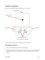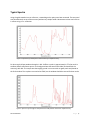
1
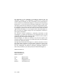
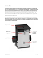
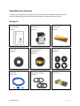
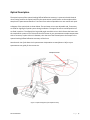
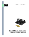
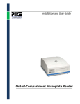
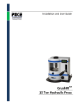
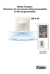
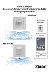
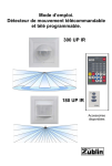
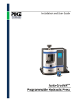
Installation and User Guide
UpIR – Out-of-Compartment
Diffuse Reflectance Accessory
The information in this publication is provided for reference only. All
information contained in this publication is believed to be correct and
complete. PIKE Technologies, Inc. shall not be liable for errors contained herein
nor for incidental or consequential damages in connection with the furnishing,
performance, or use of this material. All product specifications, as well as the
information contained in this publication, are subject to change without notice.
This publication may contain or reference information and products protected
by copyrights or patents and does not convey any license under the patent
rights of PIKE Technologies, Inc. nor the rights of others. PIKE Technologies, Inc.
does not assume any liability arising out of any infringements of patents or
other rights of third parties.
This document contains confidential or proprietary information of PIKE
Technologies, Inc. Neither this document nor the information herein is to be
reproduced, distributed, used or disclosed, either in whole or in part, except as
specifically authorized by PIKE Technologies, Inc.
PIKE Technologies, Inc. makes no warranty of any kind with regard to this
material including, but not limited to, the implied warranties of merchantability
and fitness for a particular purpose.
Copyright 1991-2013 by PIKE Technologies, Inc., Madison, WI 53719. Printed in
the United States of America. All world rights reserved. No part of this
publication may be stored in a retrieval system, transmitted, or reproduced in
any way, including but not limited to, photocopy, photograph, magnetic or
other record, without the prior written permission of PIKE Technologies, Inc.
Address Comments to:
PIKE Technologies, Inc.
6125 Cottonwood Drive
Madison, WI 53719
Phone
Fax
E-mail
Web Site
Jan. 1, 2013
(608) 274-2721
(608) 274-0103
[email protected]
www.piketech.com
Contents
Introduction
Unpacking Your Accessory
Packing List
Optical Description
Installation and Alignment
Preparing the Spectrometer
Preparing the Accessory
Alignment of the Accessory
Sample Placement
Typical Spectra
Precautions
Replacement Parts and Options
1
2
2
3
4
4
5
5
6
7
8
8
Introduction
The PIKE Technologies Upward Looking Diffuse Reflection Accessory is an ideal device to measure the
wide angle reflectance of samples with an easy face-down sample placement. The design employs a high
efficiency fixed ellipsoidal reflector to collect the maximum amount of diffusely reflected energy from
the sample. The optical elements of the accessory are all reflective, thus the spectral range covers both
the mid and near-infrared range. The 044-10XX series UpIR has aluminum reflective elements. The
optical elements of the 044- 60XX series UpIR are gold coated to provide the maximum signal possible
for both mid and near IR applications.
The sample position is on the top surface of the accessory. The sample position can be covered by an
optional IR or NIR transparent window, upon which a sample may be placed for the analysis of powders.
An optional vial holder is available for the analysis of the Upward Looking Diffuse Reflection Accessory is
available for most FT-IR Spectrometers.
Sample Position
Thumb Screws
(to remove
front panel)
Sample Focus
Adjustment
Purge Seals to
Interferometer
Purge Tubing
Connection
Figure 1. The UpIR Accessory
PN 350-044000-02
P a g e |1
Unpacking Your Accessory
In order for you to quickly verify receipt of your accessory, we have included a packing list. Please
inspect the package carefully. Contact PIKE Technologies if any discrepancies are noticed.
Packing List
User Manual
UpIR Accessory
Gold-Coated Alignment Mirror
PN 350-0044000
PN 044-10XX
PN 300-0002
Quantity 1
Quantity 1
Quantity 1
Window Mount
PN 044-3030
Powders Sampling Insert
with ZnSe Window
Sample Masks, various sizes
PN 044-3050
Quantity 1
PN 044-3040
Quantity 4
Quantity 1
Purge Tubing Kit
Purge Seals
Hex Wrenches
PN 025-3055
PN 055-0020, 055-0021
Quantity 1 Set
Quantity 1 Kit
Quantity 8
PN 350-044000-02
P a g e |2
Optical Description
The optical system of the Upward Looking Diffuse Reflection Accessory is symmetrical with identical
mirrors being used for the optical path from the spectrometer interferometer to the sample and the
sample to the spectrometer detector. Two flat mirrors and an ellipsoidal mirror are used in each path.
A diagram of the optical path is shown below. The two lower mirrors are adjustable and, if necessary,
are used for aligning the optical system during installation. The upper flat mirrors and ellipsoid mirror
are fixed in position. The ellipsoid is a large solid angle monolithic mirror which focuses the beam onto
the sample with a power of 3X. This means that if the beam in your spectrometer sample compartment
with no accessory in place is 9mm in diameter, then the size of the focused spot at the sample in the
Upward Looking Diffuse Reflection Accessory will be 3 mm.
Note that the size of the beam in the spectrometer is dependent on manufacturer. Refer to your
spectrometer user guide for the correct size.
Sample Position
Figure 2. Optical diagram of the UpIR accessory
PN 350-044000-02
P a g e |3
Installation and Alignment
Inspect the drawing below and locate the indicated items on your accessory.
Sample Position
Micrometer Focus
Adjustment
Purge Tube
Purge Tube
Mirror Alignment Screws
Figure 3. Front interior view of the UpIR
To install the accessory in your sample compartment perform the following:
Preparing the Spectrometer
1. Remove any sample holder present in the sample compartment.
2. Scan a background with your FTIR software and save either in memory or on disk, depending on the
software you are using. This single beam spectrum can be used to verify the performance of the
system.
PN 350-044000-02
P a g e |4
Preparing the Accessory
1. Place the accessory into the sample compartment. Using the 3/32” wrench provided, loosen the
screws on the two purge seal tubes located on the sides of the accessory. Push the tubes toward the
side walls of the spectrometer. This will seal the accessory in the sample compartment. Purge tubing
provided with the instrument can be connected on the front of the accessory for purging the
accessory housing.
2. Place the accessory in the sample compartment. Some configurations of the accessory include their
own instrument sample compartment mounting plate. This plate may be secured in place without
requiring access to the inside of the accessory.
3. If your accessory does not contain an instrument sample compartment baseplate, remove the front
cover of the accessory. This cover is held in place by six thumbscrews. Inside the accessory are two
mirror mounts and a base fixing position. Tighten the screw in place.
Alignment of the Accessory
1. Place the gold-coated alignment mirror onto the top surface of the accessory with the mirror
surface facing down.
T
2. Set up the FTIR software to alignment or monitor mode and note the size of the interferogram. Turn
the focus adjust micrometer to raise and lower the sample stage to achieve maximum throughput.
The gap between the sample plate and body of the accessory should be about ¼”.
Figure 4. Typical throughput curve obtained with a gold mirror as sample. The background was
the instrument open beam without any accessories. Typical throughput of a well-aligned UpIR
should be better than 40% T.
PN 350-044000-02
P a g e |5
If the throughput of the accessory is above 40%T at 1000 cm-1, the alignment is acceptable. If the
throughput is less than 40%T, the mirrors inside the accessory should be adjusted:
1. Remove the six thumbscrews holding the front cover in place and remove the cover. Behind this
cover, there are two adjustable mirrors which are used for alignment.
2. Adjust the output adjustable mirror first. This is the mirror that is the closest to the instrument
detector. Turn both screws on this mirror mount to maximize throughput.
3. Adjust the focus micrometer again to maximize throughput.
4. Adjust the input adjustable mirror. This is the mirror that is the closest to the instrument
interferometer. Turn both screws on this mirror mount to maximize throughput.
5. Adjust the focus micrometer to maximize throughput.
6. Repeat the last four steps until there is no further increase in signal. Typically, with this alignment
procedure you should achieve a signal throughput which is at least 40% of the signal that was
present before the accessory was placed into the sample compartment. Replace the front cover and
secure in place with the six thumb screws. Your accessory is ready for sample measurements.
Sample Placement
The UpIR accessory is typically used by placing the sample directly on top of the accessory. When the
sample is smaller than the opening on top of the accessory, a sample holder mask should be used. A
sample mask is included in your accessory kit. For powders or other samples with smaller particles, a
sample cup can be used.
A ZnSe powder holder is enclosed with the accessory. Powder holders can be manufactured with different
window materials. The standard holder has a ZnSe window. There is an opening with two finger access
slots to help insert and remove sample holders. Please make sure that the holders are properly positioned
in the opening, so that the sample is situated in the plane of the top of the UpIR top plate.
PN 350-044000-02
P a g e |6
Typical Spectra
Using the gold-coated mirror as reference, a matte beige color paint panel was measured. The test panel
was placed directly on top of the accessory without any sample holder. Measurement time was less than
1 minute using 4 cm-1 resolution.
Figure 5. Spectrum of coated panel collected directly on UpIR accessory
For best results, dilute powdered samples in KBr. Caffeine crystals in approximately 1-5% w/w result in
excellent diffuse reflectance spectra. The background was the same ZnSe holder (enclosed with the
accessory) with KBr. The sample was thoroughly ground in a mortar with an agate pestle and placed on
the ZnSe window. The cup does not need to be filled, but the window should be covered for best results.
Figure 6. Spectrum of 2% caffeine sample diluted in KBr powder collected on UpIR accessory
PN 350-044000-02
P a g e |7
Precautions
In order to provide the maximum transmission in the infrared and near infrared, with the minimum
spectral interference, the mirrors used in the 044-60XX version of the UpIR device are uncoated (bare)
gold on the mirror substrates. Since the coatings are soft, care must be taken to avoid damage.
Normally, these mirrors will not need cleaning since they are contained within the housing of the
accessory. If they do need cleaning, use a clean dry supply of air to blow off any dust. Under no
circumstances must the mirrors be rubbed with paper products such as “Kleenex” since this will scratch
the mirror coating.
Replacement Parts and Options
Part Number
044-60XX
044-3030
044-3040
044-3010
044-3020
160-1155
160-1307
160-1201
160-5000
160-8010
161-5050
Description
UpIR Accessory – with Gold-Coated Optics
Solids Sampling Insert
Powders Sampling Insert
21 mm Glass Vial Holder
Sample Vials with Threaded Caps, 21 mm x 70 mm, (200 per package)
25 x 2 mm ZnSe Window
25 x 2 mm Ge Window
25 x 2 mm AMTIR Window
25 x 2 mm Sapphire Window
KBr Powder, 100 g
Mortar and Pestle, 50 mm
Some options are available for purchase directly on-line at www.piketech.com.
PN 350-044000-02
P a g e |8
6125 Cottonwood Drive · Madison, WI 53719-5120 · (608) 274-2721 (TEL) · (608) 274-0103 (FAX)
[email protected] · www.piketech.com