1
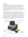
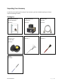
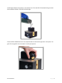
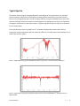
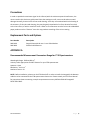
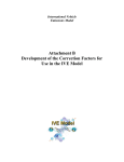
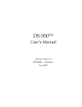
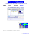
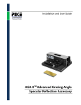
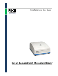
Installation and User Guide
IntegratIRTM Mid-IR Integrating Sphere
The information in this publication is provided for reference only. All
information contained in this publication is believed to be correct and
complete. PIKE Technologies, Inc. shall not be liable for errors contained herein
nor for incidental or consequential damages in connection with the furnishing,
performance, or use of this material. All product specifications, as well as the
information contained in this publication, are subject to change without notice.
This publication may contain or reference information and products protected
by copyrights or patents and does not convey any license under the patent
rights of PIKE Technologies, Inc. nor the rights of others. PIKE Technologies, Inc.
does not assume any liability arising out of any infringements of patents or
other rights of third parties.
This document contains confidential or proprietary information of PIKE
Technologies, Inc. Neither this document nor the information herein is to be
reproduced, distributed, used or disclosed, either in whole or in part, except as
specifically authorized by PIKE Technologies, Inc.
PIKE Technologies, Inc. makes no warranty of any kind with regard to this
material including, but not limited to, the implied warranties of merchantability
and fitness for a particular purpose.
Copyright 1991-2012 by PIKE Technologies, Inc., Madison, WI 53719. Printed in
the United States of America. All world rights reserved. No part of this
publication may be stored in a retrieval system, transmitted, or reproduced in
any way, including but not limited to, photocopy, photograph, magnetic or
other record, without the prior written permission of PIKE Technologies, Inc.
Address Comments to:
PIKE Technologies, Inc.
6125 Cottonwood Drive
Madison, WI 53719
Phone
Fax
E-mail
Web Site
Jan. 1, 2012
(608) 274-2721
(608) 274-0103
[email protected]
www.piketech.com
Contents
Introduction
1
Unpacking Your Accessory
2
Packing List
Installation
2
3
MCT Liquid Nitrogen Filling and Stabilization
Adjustment
3
5
Sample Preparation
Sample/Reference Selection Mirror
Measurement without Substitution
5
6
6
Typical Spectra
7
Precautions
8
Replacement Parts and Options
8
APPENDIX
8
Introduction
IntegratIR™ series Mid-Infrared Integrating Sphere module is a compact sampling accessory for
measuring the diffuse reflectance of a wide variety of solid materials. The IntegratIR™ module features a
3" high reflectivity gold coated integrating sphere and a high-speed, low-noise liquid nitrogen cooled
Mercury-Cadmium-Telluride (MCT) detector with transfer optics and interface electronics. The
IntegratIR™ fits in the sample compartment of the FTIR spectrometer and connects to the internal
detector port of the spectrometer. The 18 mm diameter opening on top of the integrating sphere is the
sample window through which the sample is illuminated. The samples are placed horizontally on the
sphere for direct illumination.
An additional sample plate is available with a built-in ZnSe window. Using the ZnSe window as a
sampling port, powders can also be measured on the top of the integrating sphere. The window is
bonded and sealed to protect the sphere from corrosive materials and contamination. In addition to the
main function of diffuse reflectance measurements, the IntegratIR can also be used to measure diffuse
transmittance. On the illumination port side of the device there is a standard 2”x3” slide position which
allows thin samples such as polymer films or other thin sheets of materials to be brought into the
infrared beam. The integrating sphere, positioned very close to the partially transmitting, partially
scattering sample, collects all infrared light emerging from the sample. The gold plated sample slide
included with your IntegratIR serves as a sample mounting surface and can also serve as an aperture
controlling the beam for minimum background scatter.
Detector Cable Connection
Temperature
Indicators
Detector Dewar
Sample/Reference
Position Knob
Purge Tube Connector
Diffuse Gold Reference
with Protective Cap
Figure 1. Components of the IntegratIR Accessory
PN 350-048100-01
P a g e |1
Unpacking Your Accessory
In order for you to quickly verify receipt of your accessory, we have included a packing list. Please
inspect the package carefully.
Packing List
IntegratIR User Manual
IntegratIR Accessory
Detector Cable
PN 350-0481000-01
PN 048-10XX
048-3000
Quantity 1
Quantity 1
Quantity 1
Gold Reference Mirror with
Protective Cap
Liquid Nitrogen Funnel
Quantity 1
Camel Hair Brush
Quantity 1
PN 048-3000
Quantity 1
Spatula
Quantity 1
PN 350-048100-01
P a g e |2
Installation
Before installation, make sure the spectrometer is working in the mid-infrared region without the
IntegratIR. Please consult the manufacturer of the FT-IR spectrometer for proper operation. This may
involve replacing the beam splitter and source to optimize for the 4000 to 600 cm-1 wavelength region of
the IntegratIR. It is advisable to perform an alignment of the interferometer before inserting the
IntegratIR into the sample compartment. Each IntegratIR unit is custom manufactured to interface with
a specific model FTIR Spectrometer. Operation with a different model may require a factory conversion
to be done by PIKE Technologies. Place the accessory in the sample compartment of the spectrometer.
The pin mounting of the accessory plate assures the alignment of the accessory relative to the beam
coming from the spectrometer. Connect the detector cable to the spectrometer.
CAUTION: Make sure power to the spectrometer bench and the IntegratIR are off before
connecting the detector cable. For ThermoFisher instruments use the cable attached to the
15 pin D connector in the sample compartment of the spectrometer. Select the appropriate source,
optical path and detector. Please consult the software manual provided by the spectrometer
manufacturer concerning how to perform the detector and source selection. For best results please use
parameters in Appendix A.
To connect the IntegratIR, please turn off the spectrometer. After the accessory is connected, power up
the instrument.
The accessory can be directly purged via the purge port on the front panel.
MCT Liquid Nitrogen Filling and Stabilization
Fill the MCT detector with liquid nitrogen using the funnel included with the accessory.
WARNING: Wear safety goggles and protective clothing when handling liquid nitrogen. Exposure to
liquid nitrogen will cause severe skin or eye injury.
Pour a small amount of liquid nitrogen into the funnel and wait for it to drain into the Dewar of the
detector. Add additional small amounts of liquid nitrogen until the detector is filled. Allow the detector
to stabilize for about 10 minutes and then top it off with a final amount of liquid nitrogen to completely
fill the liquid nitrogen Dewar. A lit green LED light indicates the Dewar contains liquid nitrogen and is
beginning the detector cooling process or is sufficiently cooled. It is not an indication that the accessory
is necessarily ready for use. Be sure to wait a 10 minute equilibrium time after the Dewar has been
completely filled. Observing a stable interferogram is another indication that the HWG accessory is
ready for measurements. An insufficiently cooled detector will produce a low and unsteady signal. The
PN 350-048100-01
P a g e |3
red LED light indicates the accessory is not ready for use. If the red LED is illuminated during use check
that the detector Dewar is filled with liquid nitrogen.
Place the Diffuse Gold Reference on the sample window to maximize the light level in the sphere. The
gain of the IntegratIR is set to around 4-5 V with open aperture.
PN 350-048100-01
P a g e |4
Adjustment
The accessory has been aligned and tested to ensure that it performs to specifications and no additional
alignment is necessary.
Sample Preparation
Sampling with the IntegratIR is as easy as placing the sample on the optical window on the top of the
accessory. For plastic sheets, painted test panels and other flat samples the reproducible sample
positioning has to be assured. If the sample does not lay flat under its own weight, a small weight could
be placed on the sample to press it against the window or open port if the window plate is removed to
aid in the accurate and repeatable sampling. Other materials, such as powders and pastes can be
directly placed on the ZnSe window. The choice whether to use the window or to place the sample
directly on the integrating sphere depends on the type of sample. The window is sealed using epoxy
compound, and can be cleaned preferably with alcohol or with acetone in the case of more difficult
samples. In all cases, the accessory is measuring the reflected light, thus transparent materials, films
produce very small signal. In certain cases a reflective mirror can aid in returning the near-infrared light
to the sphere detector. Please note that the reflectance of the ZnSe affects the measurement, the
reflected light is added to the reflectance of the sample. For absolute reflectance measurement place
the sample directly on the sample port of the sphere.
Use Gold Reference placed on the window for background spectra and for interferometer alignment.
IMPORTANT NOTE: After use please replace protective cap to avoid damage or contamination to gold
surface.
Samples need to be presented to the spectrometer in an optically uniform and reproducible fashion to
obtain the same spectrum every time. Parameters that have significant effect on the samples are
particle size and distribution, crystallinity, phase (melted or solidified oils for example have very
different spectra!), compression, temperature (especially water containing samples) and other physical
or chemical differences.
PN 350-048100-01
P a g e |5
Sample/Reference Selection Mirror
On the front of the IntegratIR module there is a knob that selects the sample or reference positions.
IMPORTANT NOTE: Please move the selector in between the SAMPLE and REFERENCE positions only.
When the selected positions are reached, it will click in place to produce reproducible repositioning of
the gold mirror inside the sphere. There are two different ways of using the Mid-IR IntegratIR. The
mirror can be left in the SAMPLE position and the background can be measured first using the Gold
Reference supplied with the IntegratIR. After the background is collected, the reference is substituted
with your sample and the spectrometer should collect the sample spectrum. In this mode the
Sample/Reference Mirror should be left in SAMPLE position. This is called the substitution method,
because the reference is substituted with the sample.
Measurement without Substitution
The IntegratIR has another measurement mode. The Taylor method of measurement is made by
LEAVING THE SAMPLE on top of the sphere at the sample port and moving the Selector Mirror to
REFERENCE position to measure the background and back to SAMPLE measuring the sample spectrum.
PN 350-048100-01
P a g e |6
Typical Spectra
The spectral results using the IntegratIR depend to some degree on the spectrometer it is used with.
Source intensities, shape of the infrared beam, the beam splitter characteristics vary from bench to
bench, thus the single beam spectra could be slightly different. Using the Gold Reference or other well
characterized highly reflective standard and ratioing against this background corrects for the individual
throughput characteristics of the spectrometers. A typical single beam spectrum and a zero reflectance
line are shown below.
The enclosed spectrum was recorded at 4 cm-1 resolution showing ambient water vapor and CO2.
Purging the sample compartment will also reduce this effect for increased spectral reproducibility in the
water vapor and CO2 regions.
Figure 1. Single beam energy of the IntegratIR. Ratio of two consecutive 1 min spectra of Gold Reference
Figure 2. Single beam energy of the IntegratIR. Typical noise level around 1800-2200 cm-1 should be less than
900 uAbs RMS.
PN 350-048100-01
P a g e |7
Precautions
In order to provide the maximum signal in the infrared, with the minimum spectral interference, the
mirrors used in this device are gold coated. Since the coatings are soft, care must be taken to avoid
damage. Normally, these mirrors will not need cleaning, since they are contained within the housing of
the accessory. If they do need cleaning, they may be gently wiped with a lint-free, abrasive-free cloth,
such as lens tissue, or with a camel hair brush. Under no circumstances must the mirrors be rubbed with
paper products such as “Kleenex” since this may produce scratching of the mirror coating.
Replacement Parts and Options
Part Number
Description
048-0100
048-3000
Sample Plate with 18 mm x 2 mm ZnSe Window
Diffuse Gold Reference
APPENDIX A
Recommended Measurement Parameters Range for FT-IR Spectrometers
Wavelength Range: 5000 to 600 cm-1
Velocity: select appropriate for MCT detector for your FTIR spectrometer
Aperture: Open
Resolution: 4 or 8 cm-1
Number of scans: 64
NOTE: Before installation, please turn the FTIR Bench off. In order to install the IntegratIR, the detector
cable has to be connected to the FTIR spectrometer electronics. Please consult your FTIR User Manual
for instructions about connecting a sample compartment accessory INSTALLATION OF IntegratIR
DETECTOR CABLE.
PN 350-048100-01
P a g e |8
6125 Cottonwood Drive · Madison, WI 53719-5120 · (608) 274-2721 (TEL) · (608) 274-0103 (FAX)
[email protected] · www.piketech.com