1
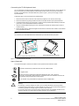
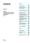
Product Information
SIMATIC
TD 200 Operator Interface Module
X 2
as of Version 3 4
TD 200 Operator Interface Module Release 2.1 or greater
The new release of the TD 200 Operator Interface Module is now available. The order number for this module is
6ES7 272--0AA30--0YA0. This data sheet describes the new features of this module. For more information about
the TD 200 Operator Interface module, refer to the TD 200 Operator Interface User Manual.
STEP 7--Micro/WIN version 3.2, Service Pack 4 or later is required for this release of the TD 200. Previous
software versions may appear and operate differently, and may not support all the TD 200 features described in
this data sheet.
New Features
This new release of the TD 200 includes the following features:
!
Supports Baltic, Hebrew, Greek, Latin 2, and Turkish (Latin 5) character sets
!
Supports momentary contacts for function keys
!
Improved up arrow, down arrow, and enter key functionality
!
Allows the PLC program to place the TD 200 in edit mode
!
Newly designed module housing to reduce water damage to the customized label
Momentary Contacts for Function Keys
All TD 200 function keys are now either momentary contact or operate in the TD 200 default mode. The TD 200
uses the most significant bit of the M Byte address as a flag to tell the TD 200 to treat the function keys as
momentary contacts. If the most significant bit is 1, the momentary mode is selected. If the most significant bit is 0,
the TD 200 default mode is selected. In momentary mode, the M bit is set when you press a function key, and
cleared when you release the function key. In TD 200 default mode, the TD 200 writes a 1 to the specified M bit
when you press the function key.
Improved Up Arrow, Down Arrow, and Enter Key Functionality
The TD 200 can now more precisely control the TD 200 display. When you press the up arrow, down arrow or
enter keys, the TD 200 writes status bits for these keys to the CPU. The CPU controls the TD 200 display and
limits the ability to scroll through messages unless the CPU program allows it. The TD 200 sets the up arrow,
down arrow, or the enter status bit each time you press one of these keys. The TD 200 must be in normal Display
mode, and there cannot be more than one message on the display. These status bits are not written when the
TD 200 is in the Menu mode, or when a variable is being edited.
Automatic Edit Mode
The PLC program can now place the TD 200 in edit mode. When a message requiring editing is displayed, the
automatic edit bit in the least significant byte (LSB) of the format word allows your program to place the TD 200 in
edit mode for the specified variable. When the TD 200 reads a message from the CPU, it checks all the variables
in the message to see if the automatic edit bit is set. The TD 200 then places the cursor on the first variable with
the automatic edit bit set. You can then edit the variable in the standard manner.
If the variable is password protected when the message is enabled, the TD 200 notes the password protected
status of the edit. The TD 200 displays the password screen only when you start to edit the variable. For more
information about TD 200 passwords, refer to the TD 200 Operator Interface User Manual.
6ES7 272--0AA30--0YA0
Copyright 2003 by Siemens Energy & Automation, Inc.
A5E00211242--01
Customizing the TD 200 Keyboard Label
You can customize the TD 200 keyboard by designating up to 4 keys for particular functions. The TD 200 has nine
keys. Five of these keys provide predefined context-sensitive functions, and four keys provide user-defined
functions. The keyboard has a removeable label insert (shown in Figure 1), so that you can supply a custom
keyboard template.
Follow these steps to remove and insert the TD 200 label insert.
1. Remove the three screws on the back of the module and pull apart the cover from the back housing.
2. Remove the label insert by pulling the label insert tab out of the label slot with a pair of pointed tweezers.
3. Customize the label insert on the reverse side or create a custom keyboard template following the dimension
guide shown in the TD 200 Operator Interface User Manual.
4. Insert the customized label by placing the corner of the label into the label slot. Rotate the label so that it is
oriented correctly.
5. Restore the back housing. Replace and tighten the three screws on the back of the module to ensure that the
cover and housing are secure.
Note
You must insert your customized label into the TD 200 before you mount the TD 200 in your panel.
Tab of label insert
Use tweezers to grasp tab of the label insert
Figure 1
Pull the label insert from the TD 200
TD 200 Keyboard Label Insert
Agency Approvals
The characters stamped on a device are indicative of the requirements which that device meets:
C
US
Underwriters Laboratories (UL) 60950 and CSA C222.2 No. 60950 standard
UL recognition mark
FM
APPROVED
FM approval to Factory Mutual Approval Standard Class Number 3611, Class I, Division 2,
Group A, B, C, D, and Class I, Zone 2, Group IIC. Temperature class T5 is adhered to when the ambient temperature during operation does not exceed 60°C.
Note for Australia: Our product fulfills the requirements for Norm AS/NZS 3548
!
Warning
Personal injury or property damage can result if you do not follow FM hazardous location guidelines.
In hazardous areas, personal injury or property damage can result if you close or disconnect an electrical
circuit during operation (for example, plug-in connections, fuses, switches).
Do not close or disconnect any live circuits unless explosion hazards can be definitely excluded. Do not
disconnect while the circuit is live unless the location is known to be non-hazardous.
2
6ES7 272--0AA30--0YA0
Product Information SIMATIC TD 200 Operator Interface Module
A5E00211242--01