1
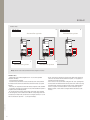
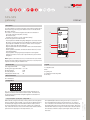
TECHNICAL SHEET SCS-SCS gateway 0 035 62 Description The SCS/SCS gateway is an interface that provides communication among BUS systems with SCS technology, even if they perform different functions. The interface has two BUS clamps, IN and OUT. On the front is a C key for virtual configuration and a LED for the notification of: - correct power supply and configuration (on steady), - BUS not detected (off), - configuration not detected or incorrect configuration (flashing). The device may operate in four different modes: - Physical expansion for MY HOME and Lightingh Management: can increase the total BUS length or exceed the absorption limit of 1200 mA for the individual power supply. - Logical expansion for MY HOME: can increase the number of devices of a system, which is 81 (max 9 rooms with 9 light points each). - Burglar alarm/automation interface for MY HOME: it allows communication between these two systems. - Galvanic separation for MY HOME: can interface two different functions (ex.: Sound system with Automation). - Physical separation: it brings together physical expansion mode and galvanic separation mode features. It can be used in systems with devices preset for virtual configuration. 5 OUT C 4 3 IN 2 1 NOTE: regardless of the interface mode of use, it must be taken into account that the two Buses connected constitute at all effects two systems, and, as such, they must be subjected to all existing sizing and installation rules. Technical data Power supply from SCS BUS: Operating power supply with SCS BUS: IN clamp absorption: OUT clamp absorption: Dissipated power with max. load: Legend 27 Vdc 18 – 27 Vdc 25 mA 5 mA 1W Dimensional data 1. 2. 3. 4. 5. Configurator socket BUS Signalling LED Pushbutton for virtual configuration OUT clamp Size: 2 DIN modules Configuration I1 I2 I3 I4 MOD The l1, l2, l3, and l4 sockets are used to univocally identify, using numeric configurators, the addresses of the interfaces inside the system. The interface may be configured also using the Virtual Configuration application as indicated in the software User Manual. - On the input BUS (IN) the addresses must go from A=0 / PL=1 and A=3 / PL=1. - On the output BUS (OUT) the addresses must be beween A=3 / PL=3 and A=9 / PL=9 or the address of the next interface. As it can be seen from the example, all the automation BUS 1 addresses are lower than that of the interface, while all the automation BUS 2 addresses are higher; the interface address therefore separates all the addresses of which the complete system might be made up of into two or more blocks. 1 LG00036-c-UK With the interface configured in this mode, it will be possible to extend the physical limit of the maximum length of the BUS, or exceed the limit of 1200 mA delivered by the individual power supply, but not the maximum number of actuators (max. 81). The positions identified with I1 and I2 must not be configured. The “separation address” between the two buses connected to the interface must instead be defined in positions I3 and I4. Supposing as in the example that I3=3, I4=2: SCS BUS SYSTEm 1) “Physical expansion” operating mode - configure MOD = 1 - 0 035 62 Installation example 2 A/PL = 33 53 Automation system Automation system OUT OUT OUT C IN OUT OUT I1 I2 I3 I4 MOD = = = = = – – 3 2 1 C IN IN A/PL = 01 31 Automation system OUT I1 I1 I1 I1 MOD = = = = = – – 5 4 1 C IN IN 1 4 A/PL = 78 175 (*) I1 I2 I3 I4 MOD = = = = = – – 7 7 1 IN 3 A/PL = 55 76 Automation system Note (*): maximum number of addresses available with virtual configuration of the devices. LG00036-c-UK Installation rules: - Configure both I3 and I4 with configurators from 1 to 9, to set the separation between the two Buses. - I1 and I2 must not be configured. - If several interfaces are installed in series, the addresses of the devices between one interface and the other must be within those of the two interfaces (see system example). - In this mode, it is not possible to install two interfaces in parallel on the same BUS. - It is possible to install up to four interfaces in series, which subdivide the system in 5 separate sections, individually powered. - The scenario module, the memory module and the devices that can be configured in self-learning mode, must be installed on the BUS line corresponding to their own local address (for example if the scenario module is configured as A=0 / PL=1, it will have to be installed on system No. 1 – see the system example). 2 - All the control devices configured to send Point-point, Room, Group and General controls can be connected on either branch of the system (1 or 2) regardless of their addresses in A and PL positions. - This is also true in the case of actuators configured in the “slave” operating mode. - Interface allows the transit between the various systems of the Point-Point, Group, Room and General controls. As an example, install a control configured with A=1 and PL=5 in system 2 to control actuator A=1 and PL=5 installed in system 1. - Within the system, no device must be configured with the same address as the interface. TECHNICAL SHEET 0 035 62 2) “Logic expansion” operating mode - MOD = 2 configurator This mode enables separation of control systems, with each of them therefore capable of using all the addresses available. It is therefore possible to connect several systems to an automation BUS, with each system having all the 81 addresses available. The BUS to which all others are connected therefore operates as main riser. This BUS must necessarily belong to an automation system. It is recommended that this mode is used for systems installed in large villas or in the service/industrial sector. A typical example may be a large villa on several floors: a system may be installed for each floor, all connected to each other through another system operating as a riser. The positions identified with l1, l2 and l3 must not be configured, while in the l4 position, the address of the interface (l4 from 1 to 9) connected to the riser must be configured. Installation example 1 A/PL = 01 99 (*) Automation IN Automation OUT OUT OUT OUT OUT I1 I2 I3 I4 MOD = = = = = – – – 1 2 C IN IN 3 A/PL = 01 99 (*) Automation OUT C 2 A/PL = 01 99 (*) I1 I2 I3 I4 MOD = = = = = – – – 2 2 IN C IN I1 I2 I3 I4 MOD = = = = = – – – 3 2 IN - From the main riser (IN clamp), arrive the general controls (rolling shutters and lights), group controls (this allows a minimum centralisation of the controls, using standard devices of the control system), and power management controls (to allow positioning of the power management central unit on the riser). On the other hand, point-point controls are stopped by the interface, and therefore remain inside the individual system, including the riser. The controls of all systems other than automation, including AUXILIARY controls, travel in the two directions without any processing. In order to send controls from one system to the other, the special controls 5 739 87 and 0 672 42 may be used in extended control mode. - The interface address cannot be the same as that of other devices (e.g. configure the interface l1= -, l2= -, l3= -, l4=1 and MOD = 2, if a scenario module is configured with A = - and PL = 1). 3 LG00036-c-UK Installation rules: - Configure I4 to give a number from 1 to 9 to the Buses connected to the riser. - I1, I2 and I3 must not be configured. - The BUS of the individual system connected to the main riser must be connected to the OUT clamp of the interface. - The main riser must consist of an Automation system in which, in addition to the corresponding control devices and actuators, it will also be possible to install the Energy management central unit, temperature central unit, and the 0 035 65 scenario programmer. - In this mode up to nine interfaces may be connected to the main riser; it is possible to manage up to ten systems as if they were a single one. Each system connected to the riser can have all 81 addresses allowed. SCS BUS SYSTEm Note (*): maximum number of addresses available with physical configuration. Maximum 175 addresses may be managed with virtual configuration. 0 035 62 4) “Burglar alarm/automation interface” mode- MOD = 4 configurator - 5) Operating mode “Galvanic separation” - configurator MOD = no configuration This mode can be used to interface the Automation system to the burglar alarm system, to facilitate interaction and exchange of information between the two BUS. Thanks to this function, it is possible to remotely control the automation system using the telephone communicator. The positions identified with l1, l2 and l3 must not be configured, while in the l4 position, the address of the interface (l4 from 1 to 9) must be configured. This configuration enables keeping the power supplies of the two buses separate, allowing interfacing of different MY HOME functions (e.g. sound system and automation). In some cases, the use of this interface is necessary (for example when the sound system is installed). In other cases installation alternatives are possible; for example, it will be possible (but not compulsory) to install Temperature Control on a separate BUS, and interface it with Automation using an interface in Galvanic Separation mode. The positions identified with l1, l2 and l3 must not be configured, while in the l4 position, the address of the interface (l4 from 1 to 9) must be configured. Installation example Installation example Burglar alarm Sound system OUT OUT OUT C IN OUT I1 I2 I3 I4 MOD = = = = = – – – 1 4 C IN IN Automation LG00036-c-UK Installation rules: - Configure l4 with configurators from 1 to 9. - I1, I2 and I3 must not be configured. - The BUS of the Burglar Alarm system must be connected to the OUT clamp of the interface. - It is not possible to connect other interfaces to the Burglar Alarm system, to physically extend the BUS, or to increase the maximum number of devices. - Only one interface may be connected to the Burglar Alarm system. It is therefore not possible to connect together two Automation systems through the Burglar Alarm system. - Installation of the Automation system actuators within the Burglar Alarm system is not allowed. 4 I1 I2 I3 I4 MOD = = = = = – – – 1 – IN Automation Installation rules: - Configure l4 with configurators from 1 to 9. - I1, I2 and I3 must not be configured. - The Automation BUS must be connected to the IN clamp. The other systems must be connected to the OUT clamp (e.g. Sound System). - It is not possible to connect several Automation systems to the same Sound System. - Thanks to this mode, using the Web Server A/V it is possible to control a one-family system (a video door entry system and an Automation system, at the most subdivided into lines, following the physical and/or logic expansion mode procedure). TECHNICAL SHEET 0 035 62 6) “Physical separation” mode - MOD=6 configurator This mode brings together “physical expansion” mode and “galvanic separation” mode features. In this way it gives the possibility of extending the physical limit determined by the length of the BUS or the current supplied by the power supply, at the same time interfacing different systems, like for example the Automation system with the video door entry system, providing monitoring through the Web Server. Each system may be connected to both the OUT and the IN clamp of the interface and, differently from what is required for “physical expansion” MOD=1, the addresses of A/PL = 15 A/PL = 26 the devices of the two systems may be selected freely. In view of the above, it will no longer be necessary to indicate the system separation address in positions I3 and I4; therefore, the interface will have to be configured by assigning any of the addresses from 01 to 99, including any addresses already used by actuator devices installed in the connected systems. If several interfaces are uses, these must have different addresses. A/PL = 48 Video door entry system Automation System No. 2 OUT OUT OUT C IN OUT I1 I2 I3 I4 MOD = = = = = – – – 1 6 IN A/PL = 11 C IN I1 I2 I3 I4 MOD = = = = = – – – 2 6 IN A/PL = 35 A/PL = 62 - The scenario module and the devices that can be configured in self-learning mode can be connected to any branch of the system (no. 1 or no.2), without limitations. The memory module must be connected to the system connected to the OUT clamp of the last interface. - All control devices configure for sending Point-point, Room, Group, and General controls may be connected to any branch of the system (no.1 or no. 2), without limitation, irrespective of their respective addresses in the A and PL positions. - The above also applies to actuators configured in “slave” operating mode. - Interface 0 035 62 allows Point-point, Group, Room, and General controls to travel through the various systems. It is therefore possible to install in system no. 2 a control configured as A=1 and PL=5 that will control actuator A=1 and PL=5 installed in system no. 1. 5 LG00036-c-UK Installation rules: - Each individual system connected to the IN or OUT clamps of the interface must be powered by its own power supply. - It is possible to use up to 4 interfaces in MOD=6 for the connection of Automation and/or Energy Management, and Temperature Control systems to each other. - In case of cascade connection of several Automation and/or Energy management, and Temperature Control systems, each individual system must be connected to the OUT clamp of one interface and the IN clamp of the other. Therefore, do no connect the system to the two interfaces only using the OUT clamps. - Do not configure positions l1 and l2. - In positions l3 and l4 address l3=0 to 9 and l4=1 to 9 of the interface must be specified. This address may also correspond to that of an actuator device installed in the connected systems. If several interfaces are installed, these must have different addresses. SCS BUS SYSTEm Automation System No. 1 0 035 62 Acquisition of the addresses of the connected devices: This procedure must only be carried out after the configuration of the interface address (or several interfaces, as applicable). It is possible to select one of two modes: - using the Virtual Configurator application as indicated in the software User Manual; - pressing the interface pushbutton for at least 2 seconds. Any other interfaces in MOD=6 installed in the system will automatically acquire the configuration of the devices. Before performing this operation check that all system interfaces and actuators have their addresses configured. 7) Use of interfaces with different modes For home automation systems of a certain complexity, several systems may be integrated with interfaces configured in different modes. For example, it is possible to install a system with three interfaces in “logic expansion” mode, to connect three Automation systems to the same riser. If necessary, each one of these may be extended (physical expansion mode), or interfaced to the Burglar Alarm, Video door entry or Sound systems, using other interfaces. For example, in case of a villa consisting of several large floors. Installation example Automation Burglar alarm OUT OUT OUT OUT C IN I1 I2 I3 I4 MOD IN = = = = = – – – 2 6 C IN I1 I2 I3 I4 MOD = = = = = – – – 1 4 230 Vac IN Automation OUT OUT C IN I1 I2 I3 I4 MOD LG00036-c-UK IN 6 = = = = = – – – 1 2