1
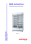
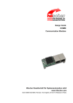
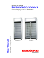
SKOPE SK Series
SK500/650/1000-3
MAN6290 Rev. 3.2 August 2008 edition
User Manual
Vertical Display Chiller - INTEGRAL
SK500/650-3
SK1000-3
SK500/650/1000-3
SKOPE SK Series Chiller - INTEGRAL
User Manual
MAN6290
Rev. 3.2 August 2008 edition.
Copyright © 2007
SKOPE Industries Limited.
All rights reserved.
SKOPE Industries Limited reserve the right to alter specifications without
notice.
is a registered trade mark of SKOPE Industries Limited.
TRADE MARK INFRINGEMENT
The SKOPE trade mark on this product is infringed if the owner, for the time
being, does any of the following:
•
Applies the trade mark to the product after their state, condition, get-up
or packaging has been altered in any manner
•
Alters, removes (including part removal) or obliterates (including part
obliteration) the trade mark on the product
Applies any other trade mark to the product
•
•
Adds to the product any written material that is likely to damage the
reputation of the trade mark
Notice of the above contractual obligations passes to:
•
Successors or assigns of the buyer
•
Future owners of the product
i
SKOPE SK500/650/1000-3
User Manual
TABLE OF CONTENTS
INSTALLATION
Introduction . . . . . . . . . . . . . . . . . . . . . . . . . . . . . . . . . . . . . . . . . . . 4
Safety Information. . . . . . . . . . . . . . . . . . . . . . . . . . . . . . . . . . . . . . 5
Positioning the Cabinet. . . . . . . . . . . . . . . . . . . . . . . . . . . . . . . . . . 6
Fitting the Sign Unit . . . . . . . . . . . . . . . . . . . . . . . . . . . . . . . . . . . . 8
Fitting the Shelves . . . . . . . . . . . . . . . . . . . . . . . . . . . . . . . . . . . . 10
Cabinet Operation. . . . . . . . . . . . . . . . . . . . . . . . . . . . . . . . . . . . . 11
ELECTRONIC CONTROLLER
Controller Display . . . . . . . . . . . . . . . . . . . . . . . . . . . . . . . . . . . . . 12
Controller Overview . . . . . . . . . . . . . . . . . . . . . . . . . . . . . . . . . . . 13
Operation Modes . . . . . . . . . . . . . . . . . . . . . . . . . . . . . . . . . . . . . 14
Day & Night Programme. . . . . . . . . . . . . . . . . . . . . . . . . . . . . . . . 16
Power Save Modes. . . . . . . . . . . . . . . . . . . . . . . . . . . . . . . . . . . . 17
Elevated Mode . . . . . . . . . . . . . . . . . . . . . . . . . . . . . . . . . . . . . . . 19
Temperature Setpoint . . . . . . . . . . . . . . . . . . . . . . . . . . . . . . . . . . 20
Controller Reset . . . . . . . . . . . . . . . . . . . . . . . . . . . . . . . . . . . . . . 21
Controller Alarms . . . . . . . . . . . . . . . . . . . . . . . . . . . . . . . . . . . . . 22
SERVICING
Lighting . . . . . . . . . . . . . . . . . . . . . . . . . . . . . . . . . . . . . . . . . . . . . 24
Cleaning . . . . . . . . . . . . . . . . . . . . . . . . . . . . . . . . . . . . . . . . . . . . 26
Unit Removal and Refitting . . . . . . . . . . . . . . . . . . . . . . . . . . . . . . 28
Troubleshooting . . . . . . . . . . . . . . . . . . . . . . . . . . . . . . . . . . . . . . 30
Contact Addresses . . . . . . . . . . . . . . . . . . . . . . . . . . . . . . . . . . . . 31
Warranty . . . . . . . . . . . . . . . . . . . . . . . . . . . . . . . . . . . . . . . . . . . . 31
SKOPE SK500/650/1000-3
TABLE OF CONTENTS
ii
INSTALLATION
Introduction
Thank you for choosing a SKOPE chiller. To ensure you get the most out of your
chiller, please read this manual prior to installation and plugging in of the chiller.
Power Saving
Although this chiller is very energy efficient, further reduction in power consumption
can be achieved. There are essentially three levels of reduced power consumption:
Level 1 - Requires no adjustment. Simply plug in the chiller for significant power
savings.
Level 2 - Utilises the ‘Day and Night Programme’, which requires a simple press of
a button for further power reduction (see page 16 for details).
Level 3 - If 100% non-perishable product is stored in the chiller, then maximum
power savings can be made with a simple one-off controller re-programme to
‘Power Save Mode 0’, and then a simple press of a button to initiate ‘Night’
programme.
Helpful Tips
Below are some helpful tips on how to reduce power consumption and service
costs:
1. Actively use the ‘Day and Night Programme’ (see page 16).
2. Ensure the condenser is kept clean. Check the condenser is clean every
month. See page 26 for instructions on cleaning the condenser.
3. Ensure good ventilation of the refrigeration unit on top of the cabinet, by
installing in an area away from low ceilings, heated appliances (ovens) and
away from direct sunlight (see pages 6-7).
4. If the chiller has to be installed in an area where there is limited ventilation
above the refrigeration unit, an optional ‘Ventilated Sign Side Kit’ is available
(see page 7).
5. Ensure the door is opened for the minimum of time. Encourage customers to
make product choice prior to opening the door.
6. Ensure the cabinet is loaded correctly with product (see page 10).
7. Consider a cost effective maintenance programme with a SKOPE Authorised
Service Agent.
4
SKOPE SK500/650/1000-3
INSTALLATION - Introduction
Safety Information
When using any electrical appliance, safety precautions should always be
observed. Read these instructions carefully and retain for future reference.
•
When used by, or near, young children or infirm persons, close supervision is
necessary. Young children should be supervised to ensure that they do not
play with the appliance.
•
Do NOT use this appliance for other than its intended use.
•
Do NOT cover the grilles or block the entry or exhaust of airflow by placing
objects up against the refrigeration unit.
•
Do NOT probe any opening.
•
Only use this appliance with voltage specified on the rating label.
•
Ensure adequate ventilation of the SKOPE refrigeration unit.
•
Be careful not to touch moving parts and hot surfaces.
•
Regulations require that all electrical work be carried out by authorised
persons. For your own safety, and that of others, ensure this is done.
•
If the supply cord becomes damaged, it must be replaced by a SKOPE
authorised service agent, or similarly qualified person, in order to avoid a
hazard.
•
If the refrigeration unit is required to be installed or removed from the cabinet,
ensure all necessary safety precautions are observed.
•
This chiller is not designed to be stable in motion. Exercise caution when
moving or transporting this chiller.
Warning:
Do NOT overload the power supply. See the rating label inside the cabinet for
power supply and current draw.
Caution:
Disconnect the cabinet from the mains power supply before attempting any
cleaning or maintenance.
SKOPE SK500/650/1000-3
INSTALLATION - Safety Information
5
Positioning the Cabinet
Location
When positioning the chiller, avoid direct sunlight and warm draughts etc. The
cabinet must NOT be situated where it is affected by hot air from adjacent
equipment, as this will compromise the airflow and performance of the chiller.
The cabinet must be positioned on a level surface for the door/s to shut and seal
correctly, and to prevent the condensate tray from overflowing. After final
positioning of the cabinet the front castors may be locked to prevent the cabinet
moving (see Figure 1 on page 7).
Installation Guidelines
The maximum recommended ambient temperature (at place of installation) for the
chiller is 43°C. This chiller will generally use less power when installed in a cooler
location.
When installing the chiller:
•
Avoid direct sunlight and warm draughts etc.
•
Allow adequate space for the door/s to open fully.
•
Ensure the cabinet is positioned on a level surface so the door/s shut and seal
correctly and to prevent the condensate tray from overflowing.
•
To provide adequate stability, the stabiliser feet provided with the SK500-3
chiller MUST be fitted to the mounting plates (underneath the front of the
cabinet) and screwed down to contact firmly with the floor (model SK500-3
only).
•
The self-closing door/s have internal torsion bars, pretensioned at the factory,
and should not require any further adjustment.
•
Do not overload the power supply. See the rating label inside the cabinet for
power supply and current draw.
Power Supply
The chiller is supplied with a 1.8m flexible power cord fitted with a 3-pin plug, which
exits out the rear of the refrigeration unit. The power cord should be retrieved before
the cabinet is positioned, as wall and partitions may make access difficult.
6
SKOPE SK500/650/1000-3
INSTALLATION - Positioning the Cabinet
Ventilation
Adequate ventilation is essential. For efficient operation of the chiller, it is essential
that adequate ventilation be provided above the refrigeration unit. Never store
cardboard cartons or other items on top of the refrigeration unit. When positioning
the cabinet, a gap of at least 200mm must be left above the refrigeration unit.
Important:
To ensure efficient and reliable operation, a minimum of 200mm clear
ventilation space is required above the refrigeration unit.
If the chiller has to be installed in an area where there is limited ventilation above
the refrigeration unit, an optional ‘Ventilated Sign Side Kit’ is available. Using the
Ventilated Sign Sides will enable the refrigeration system to operate cooler and
more efficiently. To use the Ventilated Sign Side Kit there MUST be at least 100mm
clearance on both sides of the cabinet and a minimum clearance of 50mm above
the refrigeration unit.
The Ventilated Sign Sides are intended for single installation cabinets only, there
must NOT be two or more SKOPE chillers placed side by side (see Instruction
Sheet PRN2020 for installation details).
Stabiliser Feet (SK500-3 only)
To provide adequate stability, both stabiliser feet provided with the SK500-3 chiller
MUST be fitted to the mounting screws (underneath the front of the cabinet) and
screwed down clockwise, to contact firmly with the floor (see Figure 1 below). The
foot screws onto the mounting screw anti-clockwise.
Lockable Front
Castor
Mounting Screw
Stabiliser Foot
Figure 1: SK500-3 Stabiliser Feet
SKOPE SK500/650/1000-3
INSTALLATION - Positioning the Cabinet
7
Fitting the Sign Unit
For transit purposes the sign unit and sign side panels are packed inside the
cabinet.
To Fit the Sign Unit on Top of the Cabinet:
1. Unpack the sign unit parts from inside the cabinet.
2. Fit the left and right hand sign side panels in position, with the bottom catch on
each panel facing forward (see Figure 2 below). Each side panel locates on
two retaining screws on top of the cabinet. Ensure both side panels are flush
with the edges of the cabinet before tightening the retaining screws.
3. Clip the sign rear panel into the top retaining slots at the rear of the side panels
(see Figure 3 below) and fasten with the two screws provided.
Sign Side Panel
Bottom Catch
Top Retaining Slots
Figure 2: Sign Side Panels
Sign Rear Panel
Screw
Sign Side Panel
Figure 3: Sign Rear Panel
8
SKOPE SK500/650/1000-3
INSTALLATION - Fitting the Sign Unit
4. Lift the sign assembly up and hook over the top of both the sign side panels.
5. Connect the sign plug into the ‘Sign’ socket on the front of the refrigeration unit
(see Figures 4 or 5 depending on model).
6. Swing the sign assembly downwards, aligning the controller display window
with the controller. Align the bottom clips on the sign assembly with the catch
on each side panel and press firmly to click in position (see Figure 6 below).
Figure 4:
Connecting the Sign plug
(SK500-3)
Figure 5:
Connecting the Sign plug
(SK650/1000-3)
Top Hooks
Sign Assembly
Controller Display
Window
Bottom Clip
Bottom Catch
Figure 6: Fitting the Sign Assembly
SKOPE SK500/650/1000-3
INSTALLATION - Fitting the Sign Unit
9
Fitting the Shelves
The chiller is supplied with five shelves, which may be positioned at different
heights to suit various products. Depending on the model cabinet, each shelf is held
in place with either four or six shelf clips, which engage in the shelf support strips.
The support strips are marked with a ‘+’ for easy location of shelf clips.
To fit the cabinet shelves:
1. Unpack the shelves and shelf clips from inside the cabinet.
2. Establish the desired position for the shelves and securely engage a shelf clip
in each of the shelf support strips (see Figure 7 below).
3. Sit the shelves onto the shelf support clips.
Loading Product
The chiller should be left running for 30 minutes before loading with product. When
loading the cabinet shelves with product:
•
Allow air space around all the product, to ensure even cooling and efficient
operation of the chiller.
•
Do not allow products to overhang the front of the shelf as this could prevent
the doors from shutting or cause glass breakage. Leave an airspace of at least
75mm above product loaded on the top shelf.
•
Do not exceed a maximum loading of 20kg per shelf.
•
Remove some product if the shelves are flexing or bending.
Shelf Support Strip
Shelf
Shelf Clip
‘+’ Mark
Figure 7: Shelf Clip
10
SKOPE SK500/650/1000-3
INSTALLATION - Fitting the Shelves
Cabinet Operation
Plug the chiller into the power supply and check operation of the refrigeration unit,
cabinet lighting and electronic controller. To quickly chill your product, nothing
further is required. However, if you want to take advantage of the additional power
savings, see ‘Day and Night Programme’ on page 16.
Refrigeration Unit
The compressor and evaporator and condenser fans should all operate within two
minutes from the time the cabinet is plugged in. This may be verified by listening for
compressor switch on and checking for air movement inside the cabinet.
The compressor and condenser fans should switch off and on, depending on the
cabinet temperature.
Cabinet Lighting
The cabinet lighting will be ON during ‘Day’ programme’ and OFF during ‘Night’
programme. The fluorescent lights will require a period of time to stabilise following
initial start up. The cabinet lighting will operate continuously unless the cabinet is
switched into ‘Night Programme’ (see page 16 for details) or if there is a fault.
Electronic Controller
At initial start up, the electronic controller will display the current cabinet
temperature (see page 12 for controller display).
SKOPE SK500/650/1000-3
INSTALLATION - Cabinet Operation
11
ELECTRONIC CONTROLLER
Controller Display
Figure 8: Controller Display
ITEM
ICON
FUNCTION
1
Prg / mute: To initiate ‘f’ type programme sets, press for 5 seconds. Mutes the
audible alarm (buzzer) and deactivates the alarm relay.
2
UP / aux: To scroll settings UP (in programme mode) and to switch between Day
and Night Programmes.
3
Set: If pressed for more than 2 seconds displays and / or enables changing the
temperature setpoint (see page 20).
4
DOWN / def: To scroll settings DOWN (in programme mode). Press for more than
5 seconds to initiate manual defrost.
5
COMPRESSOR: ON when the compressor and condenser fan starts. Flashes
when activation of the compressor is temporarily delayed.
6
FAN: ON when the internal cabinet fans are activated. Flashes when activation of
the fans is temporarily delayed.
7
DEFROST: ON when the defrost is activated. Flashes when the activation of the
defrost is temporarily delayed due to procedures in progress.
8
AUX: n.a.
9
ALARM: Flashes in the event of alarms.
10
CLOCK: n.a.
11
LIGHT: ON when the cabinet lighting is activated.
12
SERVICE: Flashes in the event of malfunctions.
13
HACCP: On if HACCP function is enabled. Flashes if HACCP alarm has occurred.
14
CONTINUOUS CYCLE: n.a.
Table 1: Controller Functions
12
SKOPE SK500/650/1000-3
ELECTRONIC CONTROLLER - Controller Display
Controller Overview
Function
The SKOPE electronic controller is a unique SKOPE customised CAREL ir33
controller. The controller has several new functions, additional parameters and
unique connectivity. This custom controller cannot be interchanged with a standard
CAREL ir33 controller.
Setup
The electronic controller can be setup initially by the customer to utilise the power
saving features in conjunction with product type and the required ease of use.
Further setup can be performed by an authorised service agent. The figure and
table below demonstrate the association between power saving, product type and
ease of use.
Save Power
Product
Type
Setup
Ease of
Use
Figure 9: Controller Setup
Setup
Save Power
Save Power
Reference
Up to 15%
Up to 25%
Product Type
Ease of Use
All product
All product
Non-perishable product only
Plug-in and Forget
Push button twice daily
Push button twice daily
Product Type
Perishable
NonPerishable
Elevated Temp
Power Save Mode 1
Initial setup only
Power Save Mode 0
Initial setup only
Programme mode bn2
initial setup only
Ease of Use
Do Nothing
Manual
Automatic
Plug-in and Forget
Push button twice daily
Service agent setup &
cost of maintenance
All product
All product
Customised to suit customer
and product
Table 2: Controller Setup Requirements
SKOPE SK500/650/1000-3
ELECTRONIC CONTROLLER - Controller Overview
13
Operation Modes
The SKOPE electronic controller has five different modes of operation. Four of the
modes are customer initiated, while the fifth mode is hidden and requires setup by
an authorised service agent.
1.
2.
3.
4.
5.
Plug-in and Forget
Power Saving for Perishable Product
Power Saving for Non-Perishable Product
Elevated Mode
Automatic Night Mode (hidden mode)
1. Plug-in and Forget
This is the default operation mode, which requires no initial setup or programming
of the controller for general refrigeration storage.
2. Power Saving for Perishable Product
This operation mode will save power while still maintaining cold product
temperatures suitable for food type products. This is the default power saving mode
and requires no installation setup. The ‘Day & Night’ programme must be activated
twice every business day (see page 16).
3. Power Saving for Non-Perishable Product
This operation mode will give maximum power savings for beverage type products.
The cabinet temperature will rise by approximately 10°C during ‘Night’ programme.
This mode requires some setup at installation. The power saving mode needs to be
changed from ‘1’ to ‘0’ once only. The ‘Day & Night’ programme must be activated
twice every business day (see page 16).
4. Elevated Mode
This custom operation mode is solely for use when storing elevated temperature
products and is not intended for general refrigeration storage. This programme
mode is suitable for wine, flowers or chocolate and can be set to maintain product
temperatures from 3.5° to 15°C. To use the ‘Elevated Mode’, you will need to
change the programme mode from ‘bn1’ to ‘bn2’ during installation (see page 21).
5. Automatic Night Mode
This automatic power saving mode is hidden and requires setup by a SKOPE
authorised service agent.
14
SKOPE SK500/650/1000-3
ELECTRONIC CONTROLLER - Operation Modes
Customer Setup
Operation
Mode
Product
Type
Initial
Installation
Required
Daily
Additional
Optional
Adjustment
1
Plug-in and
Forget
All Product
Do Nothing
Do Nothing
Setpoint
Adjustment
(see page 20)
2
Power
Saving for
Food
Perishable
Product
Do Nothing
Day & Night
Programme
(see page 16)
Setpoint
Adjustment
(see page 20)
3
Power
Saving for
Beverage
NonPerishable
Product
ONLY
Change
Power Save
Mode from
‘1’ to ‘0’
(see page 18)
Day & Night
Programme
(see page 16)
Setpoint
Adjustment
(see page 20)
Elevated
Mode
Wine,
chocolate,
flowers
Change
Programme to
Elevated
Mode
(see page 19)
Do Nothing
Setpoint
Adjustable
3.5° to 15°C
(see page 20)
4
Authorised Service Agent Setup
5
Automatic
Night Mode
All Product
Service Agent
Setup
Do Nothing
Set time clock
and business
hours etc.
Table 3: Controller Operation Setup
SKOPE SK500/650/1000-3
ELECTRONIC CONTROLLER - Operation Modes
15
Day & Night Programme
Introduction
Although this chiller is very energy efficient, further reduction in power consumption
can be achieved by utilising the electronic controller ‘Day & Night Programme’.
During the ‘Day’ programme the chiller operates at normal temperature with the
cabinet lights permanently on. During the ‘Night’ programme the chiller enters a
power saving mode with the cabinet lights off. Additional power savings are only
made while the chiller is in ‘Night’ programme.
Press the controller
key for 2
seconds to activate the ‘Day and Night
Programme’. The controller will display
‘nHt’ when in ‘Night’ programme or will
display ‘dAY’ at change-over then
permanently display the cabinet
temperature when in ‘Day’ programme.
Every time ‘Night’ programme is selected it automatically uses one of two
selectable ‘Power Save Modes’. At time of chiller installation the customer may
determine which Power Save Mode is suitable for their application. As standard the
SKOPE factory will dispatch the chiller set to Power Save Mode ‘1’, however if all
of the stored product is always non-perishable you can change to Power Save
Mode ‘0’ to achieve further power savings (see Table 4 below).
Power Save Modes (H22)
Mode
Description
PERISHABLE PRODUCT
Power Save Mode ‘1’ will save power while still maintaining cold product
temperatures suitable for perishable product. This is the default mode.
NON-PERISHABLE PRODUCT ONLY
Power Save Mode ‘0’ will give maximum power savings.
The cabinet temperature will rise by approx. 10°C during ‘Night’ programme.
Table 4: Power Save Modes
What is Perishable Product?
Perishable product consists of high risk foods and drinks that are likely to support
the growth of food poisoning bacteria, such as meat, fish, eggs and dairy products.
Generally, perishable product should be kept continuously cold.
16
SKOPE SK500/650/1000-3
ELECTRONIC CONTROLLER - Day & Night Programme
Power Save Modes
Power Save Mode ‘0’
(7 hours MAX duration)
A programme ONLY for Non-Perishable Product that will give maximum power
savings. This must NOT be used when the product is temperature intolerant. During
Power Save Mode the stored product temperature is not maintained and will warm
up (this is variable but typically 12°C). Power Save Mode ‘0’ is not suitable for
perishable products such as dairy, fresh meat and some fresh juices etc.
Operation during Power Save mode ‘0’:
•
Entire cabinet is off for 7 hours maximum. Only controller display is on ‘nHt’.
•
After 7 hours the chiller will enter a ‘Recovery Mode’, where the refrigeration
system will pull the product back down to normal temperature, during which
time the cabinet lights will remain off.
•
If the 7 hours is inappropriate for a particular installation (product temperatures
are too warm at shop opening), then parameter ‘H23’ could be changed. ‘H23’
is the length of time in X10 minute increments for duration of Power Save
Mode. (e.g. H23 @ 42 = 420minutes = 7 hours. To change to 5 hour Power
Save Mode change to H23 @ 30).
Power Save Mode ‘1’
(7 hours MAX duration)
A programme that will save power and maintain cold product temperatures for
perishable product. Power Save Mode ‘1’ will ensure product is always cold at start
of business trading hours.
Operation during Power Save mode ‘1’:
•
Cabinet lights are off but cold product temperatures are maintained.
•
The evaporator fans will cycle regularly during the compressor off time at 2
minutes on and 2 minutes off.
•
The compressor setpoint is offset for improved energy efficiency (parameter
‘r4’ @ 1.5" = Setpoint + 1.5°C).
SKOPE SK500/650/1000-3
ELECTRONIC CONTROLLER - Power Save Modes
17
Important:
•
As standard, the chiller is set to Power Save Mode ‘1’ (suitable for perishable
product). Power Save Mode ‘0’ is only suitable for NON-PERISHABLE product.
•
Ensure compliance with all Food Safety Requirements. If there is any doubt
about product type, and whether it is perishable, then Power Save Mode ‘1’
must be used.
•
If you are using Power Save Mode ‘0’ and are finding product temperatures too
warm at business opening hours, change back to Power Save Mode ‘1’ so that
the product will remain cold during future ‘Night Programme’ operation.
•
Both of the Power Save modes are limited to 7 hours maximum so that product
temperatures may quickly recover. If the Power Save Mode time elapses (after
7 hours), the chiller will operate normally but the lights will remain off until ‘Day’
programme is selected.
To Change the Power Save Mode (H22):
1. Press and hold the
seconds.
2. Press either the
‘H22’ is displayed.
3. Press the
key for 7
or
keys until
key.
4. Press the
or
keys to display
either ‘0’ (for Power Save Mode ‘0’) or
‘1’ (for Power Save Mode ‘1’).
5. Press and hold the
key for 7 seconds to confirm
selection. If this step is not completed within 60 seconds
all changes will be lost.
18
SKOPE SK500/650/1000-3
ELECTRONIC CONTROLLER - Power Save Modes
Elevated Mode
This operation mode is solely for use when storing elevated temperature products
and is of no use for general refrigeration storage. This programme mode is suitable
for wine, flowers or chocolate and can be set to maintain product from 3.5° to 15°C.
If you choose to use the ‘Elevated Mode’, you will need to perform a ‘Controller
Reset’ and change the programme mode to ‘bn2’ (see page 21). The controller
must never be left in programme mode ‘bn0’ as failure will occur. After selecting
‘bn2’ check and, if required, change the temperature setpoint. The temperature
setpoint default is 10°C.
Warning:
The controller must never be left in programme mode ‘bn0’ as failure will
occur.
SKOPE SK500/650/1000-3
ELECTRONIC CONTROLLER - Elevated Mode
19
Temperature Setpoint
The chiller temperature setpoint is factory set at 2.0°C. If necessary the standard
setting can be adjusted between 1.5°C and 3.5°C. In ‘Elevated Mode’ the setpoint
default is 10°C and can be adjusted from 3.5°C to 15°C.
Note: The setpoint is overridden by the minimum compressor run time of 5 minutes.
SKOPE do not recommend that the setpoint be changed unless it is absolutely
necessary, and then only by small increments at a time.
To View and Adjust the Temperature Setpoint:
1. To view the setpoint:
Press and hold the
key for 2 seconds, until
the setpoint value flashes.
2. To adjust the setpoint:
Press either the
or
required setpoint value.
keys to display the
3. Press the
key again to memorise the new
setpoint value. If this is not done within 60
seconds changes will be lost and you will need to
repeat the above procedure.
20
SKOPE SK500/650/1000-3
ELECTRONIC CONTROLLER - Temperature Setpoint
Controller Reset
To delete programme modifications and reset the controller to SKOPE default
programme or when a replacement controller is being fitted, a ‘Controller Reset’
must be performed.
To Perform a Controller Reset:
1. Unplug the chiller from the mains power supply.
2. Press and hold the
key while
plugging the chiller into the power
supply (this may require two
people). After a few seconds the
controller is reset and programme
mode ‘bn0’ is displayed. The
controller must never be left in
programme mode ‘bn0’ as failure
will occur.
3. Press the
or
keys to select
‘bn1’ for SKOPE default
programme, ‘bn2’ for Elevated
Mode or ‘bn3’ for Automatic Night
Mode.
SKOPE Default
Elevated Mode
Automatic Night Mode
4. Immediately press the
key to confirm the
preferred programme. If not confirmed within 60
seconds the chiller will remain in programme mode
‘bn0’ (and cause failure). If this occurs, repeat the
above procedure.
Note:
If after performing a ‘Controller Reset’ the cabinet lights remain off, as a once only
requirement, press the
key for 2 seconds to enter Night Mode ‘nHt’ and then
again to re-enter Day Mode ‘dAY’. The lights should then continue to work correctly.
SKOPE SK500/650/1000-3
ELECTRONIC CONTROLLER - Controller Reset
21
Controller Alarms
CODE
DISPLAY LED
BUZZER
ALARM DESCRIPTION
Flashing
on
Product HIGH temperature alarm
(auto reset)
Flashing
on
Product LOW temperature alarm
(auto reset)
Flashing
off
Refrigeration system high temperature
pre-warning (auto reset)
Flashing
on
Refrigeration system high
temperature shutdown (manual reset)
Flashing
off
Ambient probe fault (also flashes ‘rE’)
Flashing
off
Evaporator probe fault
Flashing
off
Condenser probe fault
off
Defrost over-time limit
Flashing
off
Real-time clock fault
Flashing
off
Controller E prom error
Flashing
off
Controller E prom error
None
None
-
Start defrost request
None
-
End defrost request
Table 5: Controller Alarms
22
SKOPE SK500/650/1000-3
ELECTRONIC CONTROLLER - Controller Alarms
Controller Alarms
INITIAL ACTION
FINAL ACTION
1. Check the cabinet product loading to ensure ventilation slots are not blocked
and that product does not overhang the shelves.
2. Ensure the cabinet is installed with good refrigeration unit ventilation.
3. Check and clean the condenser coil.
4. If immediate alarm recovery is required - unplug the cabinet from the power
supply for 1 minute, then reconnect to power supply.
1. Clean the condenser coil (see pages 26-27).
2. Check refrigeration ventilation. Ensure clear airpath at the top and front of
the cabinet (to extract hot air). A minimum of 200mm clear space is required
above and in front of the refrigeration unit.
3. Ensure the cabinet is installed in a suitable environment.
4. To reset the ‘CHt’ alarm - unplug the cabinet from the power supply for 1
minute, then reconnect to power supply.
If alarm persists,
contact SKOPE.
To reset alarm - unplug the cabinet from the power supply for 1 minute, then
reconnect to power supply.
None
None
Table 5: Controller Alarms (continued)
SKOPE SK500/650/1000-3
ELECTRONIC CONTROLLER - Controller Alarms
23
SERVICING
Lighting
Cabinet Interior Lights
Depending on the model cabinet, the chiller has either one or two interior side lights.
Each side light houses a 35 Watt T5 fluorescent tube (Ø16mm x 1450mm), which
may be replaced without removing shelves or product from the cabinet.
To Replace the Fluorescent Tube:
1. Disconnect the cabinet from the mains power supply.
2. Remove the side light diffuser, by compressing the back section of the diffuser
until it disengages from the aluminium housing and then push the diffuser back
(see Figure 10 below).
3. The fluorescent tube can now be removed. Revolve the tube until the pin
position allows withdrawal.
4. When refitting the new fluorescent tube ensure the printing on the tube is at the
bottom, as the tube orientation is important.
5. When refitting the diffuser, engage the back section into the housing, and then
compress and snap the front section of diffuser back into place working down
the full length of the light.
Side Light Diffuser
Fluorescent Tube
Figure 10: Replacing the Fluorescent Tube
24
SKOPE SK500/650/1000-3
SERVICING - Lighting
Cabinet Sign Light
The cabinet sign light is fitted with one fluorescent tube which can be replaced by
removing the front sign panel (see Table 6 below for the correct tube size).
Model
Fluorescent Tube
SK500-3
8 Watt T5 fluorescent tube (Ø16mm x 288mm)
SK650-3
14 Watt T5 fluorescent tube (Ø16mm x 550mm)
SK1000-3
21 Watt T5 fluorescent tube (Ø16mm x 850mm)
Table 6: Sign Light Fluorescent Tube Sizes
To Replace the Fluorescent Tube:
1. Disconnect the cabinet from the mains power supply.
2. Unclip the sign top cap. Start at one end and work along the length of the sign,
lifting the top cap up as you go (see Figure 11 below).
3. Carefully remove the sign panel away from the sign unit.
4. The fluorescent tube can now be removed. Revolve the tube until the pin
position allows withdrawal (see Figure 12 below).
5. When refitting the sign panel, ensure the top cap is firmly clipped in place.
Top Cap
Sign Panel
Figure 11:
Removing the Sign Panel
SKOPE SK500/650/1000-3
SERVICING - Lighting
Fluorescent Tube
Figure 12:
Replacing the Fluorescent Tube
25
Cleaning
When necessary, wipe both the interior and exterior of the cabinet with a damp
cloth. Ensure the cabinet is disconnected from the mains power supply before
cleaning the cabinet. Periodic cleaning of the condenser coil is also recommended.
Condenser Coil
The condenser coil is situated behind the sign unit. The condenser coil MUST be
kept clean for reliable operation and to minimise power consumption. A blocked
condenser can double normal power consumption.
To ensure trouble free performance, the condenser coil should be brushed clean
once a month (see Figure 13) and blown clean by qualified service personnel every
6 months. SKOPE recommend a preventative maintenance check every 6 to 12
months. If the electronic controller display flashes ‘cht’ the condenser coil must be
cleaned immediately.
Over time, dust may accumulate within the condenser that cannot be removed with
a brush. if this occurs, contact SKOPE to arrange for a SKOPE authorised service
agent to clean the condenser with compressed air.
Important:
If the electronic controller display flashes ‘cht’ the condenser coil must
be cleaned immediately.
To access the condenser coil:
1. Disconnect the cabinet from the mains power supply.
2. Remove the sign unit by pulling the bottom of the sign unit out to unclip from
the sign sides and then lift the sign up off the top of the sign sides.
3. Disconnect the sign plug from the electrical box socket and remove the sign
unit from the cabinet (see page 9).
4. The condenser coil is now accessible for cleaning (see Figure 13).
5. See pages 8-9 for instructions on re-fitting the sign unit.
Caution:
Disconnect the cabinet from the mains power supply before attempting any
cleaning or maintenance.
26
SKOPE SK500/650/1000-3
SERVICING - Cleaning
Condenser Coil
Figure 13: Cleaning the Condenser Coil
SKOPE SK500/650/1000-3
SERVICING - Cleaning
27
Unit Removal and Refitting
The SKOPE Cyclone refrigeration unit can easily be removed from the top of the
cabinet for transporting and moving the cabinet through doorways etc.
To remove the refrigeration unit:
Removable SKOPE Cyclone Refrigeration Unit
RH Sign Side Panel
Sign Rear Panel
2195
Sign Unit Assembly
LH Sign Side Panel
Screwdriver
Fixing Screws
HEAVY!
Approx. 40kg
Cabinet Plug
4-Pole
Electronic Controller
Figure 14: Removing the Refrigeration Unit
28
SKOPE SK500/650/1000-3
SERVICING - Unit Removal and Refitting
To refit the refrigeration unit:
Screwdriver
Fixing Screws
HEAVY!
Approx. 40kg
Cabinet Plug
4-Pole
SKOPE Cyclone
Refrigeration Unit
Electronic Controller
Sign Rear Panel
RH Sign Side Panel
Sign Plug 3-Pole
LH Sign Side Panel
Sign Unit Assembly
Figure 15: Refitting the Refrigeration Unit
SKOPE SK500/650/1000-3
SERVICING - Unit Removal and Refitting
29
Troubleshooting
Complaint
Possible Cause
Repair
1. Cabinet not
operating and no
controller display:
• Loss of power supply.
• Check mains power supply.
2. Cabinet not
operating but
controller displays
‘nHt’:
• Cabinet in ‘Night’ Programme.
• Change to ‘Day’ programme (see
page 16).
3. Cabinet lights not
operating:
• Blown cabinet fuse.
• Requires technical repair by a
SKOPE Authorised Service Agent.
• Failed fluorescent tube.
• Check fluorescent tubes.
• Cabinet in ‘Night Programme’. ‘nHt’
will be displayed on the controller.
• Change to ‘Day Programme’ for
cabinet lights to come on.
• Controller alarm.
• Determine cause and eliminate (see
pages 22-23).
• ‘Controller Reset’ performed.
• Enter ‘Night’ and then ‘Day’ mode
(see page 16).
• Unit operating too hot.
• Clean condenser. Ensure the chiller
is installed with good ventilation
above the refrigeration unit.
• Cabinet door is opened excessively.
• Keep door open for minimum time.
• ‘Day Programme’ selected.
• Utilise ‘Night ‘Programme’ outside of
business hours.
• Controller is using Power Save
Mode ‘0’.
• Change to Power Save Mode ‘1’
(see page 18).
• Restricted cabinet airflow.
• Ensure product is not blocking
airflow slots and the product is no
closer than 75mm from the cabinet
top.
• Temperature setpoint is too warm.
• Adjust setpoint (see page 20).
4. Power
consumption is
higher than
expected:
5. Product is too
warm and
spoiling:
6. Warm cabinet
• Blocked condenser.
temperatures and/ • Poor refrigeration unit ventilation.
or compressor
operating for long
periods (more
than 1 hour):
• Clean condenser (see pages 26-27).
7. Chiller operating
incorrectly after
selecting
‘Elevated Mode’:
• Perform a controller reset (see page
21). Ensure only programme modes
‘bn1’ or ‘bn2’ are selected.
Programme mode ‘bn0’ must NOT
be used.
• Programme mode ‘bn0’ has
inadvertently been selected (see
page 15).
• Ensure the cabinet is installed with
good ventilation above the
refrigeration unit. If there is limited
clearance around the top of the
cabinet, call a SKOPE Authorised
Service Agent to discuss the benefit
of fitting an extraction fan above the
refrigeration unit.
Table 7: Troubleshooting
30
SKOPE SK500/650/1000-3
SERVICING - Troubleshooting
Contact Addresses
New Zealand
SKOPE INDUSTRIES LIMITED
Head Office
PO Box 1091, Christchurch
New Zealand
Freephone: 0800 947 5673
Fax: (03) 983 3896
E-mail: [email protected]
Website: www.skope.co.nz
Australia
SKOPE AUSTRALIA PTY LTD
A.C.N. 000 384 270
PO Box 7543, Baulkham Hills B.C.
NSW 2153, Australia
Freephone: 1800 121 535
Fax: 1800 121 533
E-mail: [email protected]
Website: www.skope.com.au
Warranty
To receive a warranty for your purchased cabinet, you MUST register your cabinet
within four weeks from the date of invoice either by:
•
filling out the in-cabinet warranty form and posting or faxing it back to SKOPE
•
or filling out the online warranty form.
Cabinets that are not registered within the four weeks are not eligible for a warranty.
SKOPE SK500/650/1000-3
SERVICING - Contact Addresses
31