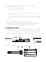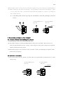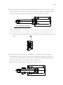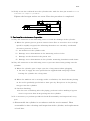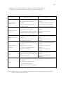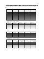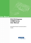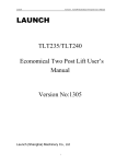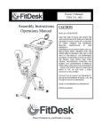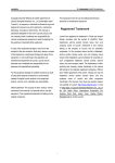
1
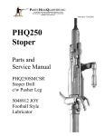
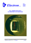
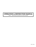
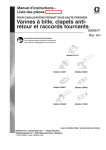
INSTRUCTION MANUAL
FOR
COMPACT CYLINDER
CHR Series:
CR Series
:
CS Series
:
CT Series
:
CAUTIONS FOR
SAFE OPERATION
10MPa
14MPa
16MPa
21MPa
● Thoroughly read the instruction manual before use
for correct operation.
● Be sure to turn OFF the power switch, completely
shut down the hydraulic source and discharge the
residual pressure before mounting and maintenance
of the cylinder.
● Be sure to apply nominal pressure when using the
cylinder.
● When injecting hydraulic fluid into the cylinder,
please take great care to prevent physical injury due
to the rapid movement of the mounting part.
NO.1
1/10
Contents
1. Cautions for use
Page
………………………………………………………………
2. Air bleeding method
…………………………………………………………
2
2
3. Disassembly procedures of the cylinder
3-1. Cautions for the cylinder disassembly … … … … … … … … … … … …
2
3-2. Disassembly of the cylinder
3
………………………………………
4. Reassembly procedures of the cylinder
4-1. Cautions before reassembling the cylinder
………………………
4-2. Cylinder reassembly … … … … … … … … … … … … … … … …
5. Cautions for maintenance inspection
4
4
……………………………………
6
6. Indication of the label attached on the cylinder body… … … … … … … …
8
7. Tightening torque of mounting bolts and driving torque of a
connector for the port … … … … … … … … … … … … … … … … …
9
※ The contents of this manual is subject to change without notice.
2/10
1. Cautions for use
(1) For mounting the cylinders, use four (4) hexagon socket cap screws (JIS B1176,
strength classification 10.9 or over).
(2) Manufacture tools for tightening the screws up to the end of the piston rod not
to apply load on the thread of the piston rod when moving the piston rod
forward.
(3) When mounting the tools on the rod, do not apply lateral load on the rod.
(4) When operating the cylinder for the first time, be sure to bleed the air while
the inner pressure of the cylinder is low. After the air bleeding, gradually
raise the pressure from low to nominal pressure when operating the cylinder.
2. Air bleeding method
(1) Bleed the air in the piping while paying attention to prevent air from
leaking into the cylinder.
(2) Bleed the air through the piping because this type of cylinder has no air
bleed valve.
(3) Wash the pipes with acid to prevent metal dust from getting into the cylinder. If
the metal dust gets into the pipes, it causes the packing damage or oil leakage.
Bleed not only the air in the cylinder but also that in the piping.
If the air remains, the following malfunctions occur.
1) The cylinder cannot be smoothly operated.
2) The speed cannot be controlled.
3) The temperature rise by an adiabatic compression causes damages on
the packing.
4) Shocks and vibrations are delivered to other equipment.
3.Disassembly procedure of the cylinder
3-1. Cautions for the cylinder disassembly
(1) Before removing the cylinder, depressurize the inside of the hydraulic circuit to
zero and turn OFF the power switch.
3/10
(2) During disassembly, take extra precaution not to damage the following:
a) The thread on the edge of the piston rod
b) The port screw surface of the cover
c) The sliding surfaces of the piston rod
* Applying strong blow on the cylinder could leave deep scratches on the
surface of the piston rod.
Accidental drop of the cylinder could also damage the thread on the piston
rod and leave impact marks. Such mishandlings could cause the cylinder
faulty.
(3) Do not use other fluids than the one specified for the packing.
If other fluids than the one specified are used for the packing, the packing
cannot be used anymore because of swelling by a chemical reaction.
3-2. Disassembly of the cylinder
(1) Loosen the hexagon socket set female screw⑫ , and then pull out the rod bush
⑧ with the face-pin wrench. At that time, if the double surface for the wrench
of the piston rod⑦ has scratch and burrs, carefully grind them. When pulling
out the rod bush, do not damage the rod bush and the packing.
(Face-pin wrench)
Deburr here.
(2) Pull out the piston rod⑦ , piston⑨ and assembly from the cylinder tube⑥ .
4/10
(3) In normal cases, since pistons are glued with a rod, they cannot be disassembled.
(4) When removing the dust packing③ , rod packing② and piston packing① , apply
a tool with the edge of spatula-like mild metal(made of copper) as shown in
the figure below.
※ : A packing and a back-up ring are installed on the rod packing in the CS
series.
Standard(Without
switch)
Standard(With
switch)
Magnet
4. Reassembly procedures of the cylinder
4-1. Cautions before reassembling the cylinder
(1) Completely clean each disassembled part.
(2) Carefully inspect all disassembled-parts that were cleaned. Then be sure to
check if abnormalities exist. If any, repair them. If the parts cannot be repaired,
replace them with new parts.
(3)Carefully inspect the seal kit of the cylinder. If they are damaged, replace them
with new good parts.
4-2. Cylinder reassembly
(1) Fit the O-ring into the piston. At this time, pay particular attention not to twist
the O-ring.
Standard(Without
switch)
Standard(With
switch)
Magnet
5/10
(2) Apply the same type of oil as the applied fluid on the inner face of the cylinder
tube, and insert the piston rod and piston assembly. When inserting the piston
rod into the tube, pay particular attention not to damage the O-ring.
Pay particular attention
not to damage the O-ring.
Mount the O-ring④ , rod packing and dust packing on the rod bush and pay
particular attention not to mount the packing in the wrong direction.
※ : A packing and a back-up ring are installed on the rod packing in the CS
series.
(3) After mounting the packing on the rod bush, apply grease on the packing.
Thereafter, fit the rod bush into the piston rod/piston assembly. In this case,
pay particular attention not to damage the rod bush and the packing. Also pay
particular attention to the double surface for wrench .
Remove burr on the double surface for wrench, if any.
6/10
(4) Fully screw the rod bush into the cylinder tube with the face-pin wrench for the
rod bush of compact cylinders.
Tighten the hexagon socket set screw. Then the procedure is completed.
5. Cautions for maintenance inspection
(1) Pay full attention to the following cases to avoid the damage of the cylinder.
-1) When the piston given a greater inersia force (due to excessive force or high
speed) is rapidly stopped, the following disorders are caused by accidental
excessive pressure or force.
a)
An inflation of the cylinder tube
b)
Damage on or deformation of the mounting tools or bolts
c)
Damage on the thread of the piston rod
d)
Damage on or deformation of the cylinder mounting foundation and frame
(2) Pay full attention to the following cases to prevent dusts from getting into the
cylinder.
-1) When the cylinder port is kept open for a long time without plugging
* Be sure to apply the rust-proof fluid or applied fluid and plug it when
leaving the cylinder for a long time.
.
-2) When the ambient air is strongly acidic or alkaline, the hard chrome plating
on the rod is gradually peeled off as time goes by. The pieces of the plating
may get into the cylinder.
-3) Careless flushing
* In the case of flushing after the piping, perform it after making a bypass
circuit to prevent dust from getting into the cylinder.
(3) It is necessary to perform periodical check (disassembly and inspection) every
year.
-1) Disassemble the cylinder in accordance with the user ’s manual. Then
reassemble it after cleaning and inspection of the cylinder, and replacement
of seal kits.
7/10
-2) Inspect the leakage and the operation before reinstallation.
-3) Replace with new seal kits at the periodical inspection.
The followings are Inspection portions and judgement manual
Inspection
Portion
Judgement criteria
1) Scratch on the sliding surfaces
Inner surface of
cylinder tube
that fingernails are slightly
caught
2) Vertical deep scratch on the
sliding surfaces
1) Scratch or striking dents on
Sliding surface of
piston rod
the sliding surfaces that
fingernails are slightly caught
2) Peeling-off of the plating due
Actions
1) Polish with papers (Around
#320).
2) If the polishing with papers
(Around #320) is impossible,
replace it with a new cylinder.
1) Polish with papers (Around
#600).
2) Replace it with a new
cylinder.
to the greater striking dents
1) A little scratch on the sliding
Sliding surface of
piston
surfaces
2) Deep scratch or big dents on
the sliding surfaces
1) A little scratch on the sliding
surfaces.
Internal surface of
rod bush
2) The degree of eccentric
abrasion is 0.3mm or more.
3) Cracks of rod bush
1) Polish with papers (Around
#320).
2) Replace it with a new
cylinder.
1) Polish with papers (Around
#320).
2) Replace it with a new
cylinder.
3) Replace it with a new
cylinder.
Seals
1) Visible abrasion and scratch.
1) Replace it with a new
2) Broken pieces of the gasket are
cylinder.
appeared outside.
2) Replace it with a new
cylinder.
Check the following items carefully depending on the intended use of
the cylinder.
Others
a) Crack of the cylinder tube,
b) Crack of the mounting
c) Thread of the rod edge and port.
(Note): With regard to the packing and gaskets, replace them with new products
during the periodical check.
8/10
6. Indications of the labels attached on the cylinder body
(1)Label
The major information on new products is indicated on the labels.
When making inquiries of them, notify the manufacturing NO. (Serial NO.).
.
MADE IN JAPAN
SERIA L No .
製造番号
TY PE
形式
D ATE
製造年月日
D582653
2005/05
CS -SA
1SA63B30
3 5 mm
READ S WI TC H
リードスイッチ
O P TIO N
オプション
C YL IND ER BO RE
シリンダ内径
63
mm
NO MINA L PRESS URE
呼び圧力
16
MPa
RO D D IA
ロッド径
35.5
PRO O F PRESSURE
試験耐圧力
21
HYDRAULIC
mm
MPa
CYLINDER
5 5 mm
(2) Label position
The label is always attached to the opposite side regardless of the
port position and foot mounting.
9/10
7. Tightening torque of mounting bolts and driving torque of a connector for the
port
(1) CS series cylinder (16MPa)
Cylinde r bo r e
( m m)
φ 32
φ 40
φ 50
φ 63
φ 80
φ 100
φ 125
φ 140
φ 150
φ 160
Mo unti ng bo lt
s ize (m m)
Tighte n ing
tor que (N・ m)
M6×P1.0
M8×P1.25
M10×P1.5
M12×P1.75
M14×P2.0
M20×P2.5
M24×P3.0
M27×P3.0
M30×P3.5
M33×P3.5
9.1
22.4
44.1
71
114
344
600
900
1180
1625
Po r t size
(Rc )
1/4
1/4
1/4
1/4
3/8
3/8
1/2
1/2
1/2
1/2
Tighte n ing
tor que (N・ m)
36
36
36
36
55
55
86
86
86
86
(2) CR series cylinder (14MPa)
Cylinde r bo r e
(m m)
φ 32
φ 40
φ 50
φ 63
φ 80
Mo unti ng bo lt
s ize (m m)
Tighte n ing
tor que (N・ m)
M6×P1.0
M8×P1.25
M10×P1.5
M12×P1.75
M14×P2.0
9.1
22.4
44.1
54
87.5
Po r t size
(Rc )
1/4
1/4
1/4
1/4
3/8
Tighte n ing
tor que (N・ m)
13
13
13
13
23
(3)CR-LD series cylinder (14MPa)
Cylinde r bo r e
(m m)
φ 32
φ 40
φ 50
φ 63
Mo unti ng bo lt
s ize (m m)
Tighte n ing
tor que (N・ m)
M8×P1.25
M10×P1.5
M12×P1.75
M14×P2.0
22.4
44.1
54
87.5
Po r t size
(Rc )
1/4
1/4
1/4
1/4
Tighte n ing
tor que (N・ m)
13
13
13
13
(4)CHR series cylinder (10MPa)
Cylinder bore Bolts size
(mm)
(mm)
φ 32
φ 40
φ 50
φ 63
φ 80
φ 100
M6×P1.0
M8×P1.25
M10×P1.5
M12×P1.75
M14×P2.0
M16×P2.0
Torque of
Port size
tightening
(Rc)
(N・m)
9.1
1/4
22.4
1/4
44.1
1/4
54
1/4
87.5
3/8
135
3/8
Torque of
tightening
(N・m)
13
13
13
13
23
23
10/10
(5)CT series cylinder (21MPa)
Cylinde r bo r e
(m m)
φ 40
φ 50
φ 63
Mo unti ng bo lt
s ize (m m)
M12×P1.75
M14×P2.0
M16×P2.0
Tighte n ing
tor que (N・ m)
71
114
175.5
Po r t size
(Rc )
1/4
1/4
3/8
Tighte n ing
tor que (N・ m)
36
36
55
※ Use mounting bolts with hexagonal socket head cap the strength classification of
which is over 10.9.
※ Note that tightening torque of mounting bolts and driving torque of a
connector are different depending on the material of the cylinder tube.