1
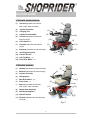
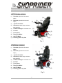
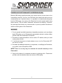
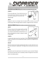
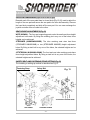
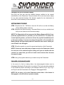
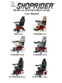
GMP ISO9001 ISO14001 ISO13485 CERTIFIED MEDICAL POWER WHEELCHAIR User Manual WIZZ 888WNL STREAMER 888WB STREAMER 888WAB STREAMER 888WSB JETSTREAM-M 888WAM JETSTREAM-L 888WAL GMP ISO9001 ISO14001 ISO13485 CERTIFIED CONTENTS INTRODUCTION page 2 FEATURE GUIDE page 2 --4 EMI WARNING page 5 – 6 SAFETY INSTRUCTIONS page 7 -- 8 WARNING, CAUTION AND INDICATION LABEL LOCATION page 9 -- 11 PREPARATION FOR USE page 12 -- 13 ADJUSTMENT PROCEDURES page 14 – 16 OPERATION INSTRUCTIONS page 17 – 18 DISASSEMBLY INSTRUCTIONS page 19 – 20 BATTERIES AND BATTERY CHARGING page 21 – 23 TROUBLESHOOTING page 24 -- 25 SPECIFICATION page 26 QUARTERLY INSPECTION page 27 DISCLAIMER page 28 ~1~ GMP ISO9001 ISO14001 ISO13485 CERTIFIED INTRODUCTION Congratulations on your purchase of our product. This Powerchair is the ultimate combination of style and comfort. The short wheelbase allows easy maneuverability within the smallest spaces both in and outdoors. The middle/rear drive wheels and electromagnetic brakes provide a safe and comfortable ride. This manual contains important information regarding the safe use of the Powerchair. Please read it carefully before using the Powerchair and make sure you understand all the instructions. FEATURE GUIDE WIZZ (888WNL) (1) Armrest (adjustable with selected (7) width, length, angle and height) (2) Joystick Controller (2) (3) Seat Supporting Post (1) (8) (With Retaining Pin) (9) (4) Charging Port (5) Footrest (adjustable with (3) selected length and angle) (6) Front Castor(6”) (7) Headrest (adjustable with (5) (4) (10) selected height) (11) (8) Backrest (adjustable with (12) (6) selected angle) (9) Captain Seat Assembly Fig. 1 (10) Chassis Shroud (11) Rear Castor (5”) (12) Middle Drive Wheel (w/ Flat Free Tire) (10”) ~2~ GMP ISO9001 ISO14001 ISO13485 CERTIFIED FEATURE GUIDE STREAMER (888WB/888WSB) (1) (7) Armrest (adjustable with selected width, length, angle and height) (2) Joystick Controller (3) Charging Port (4) Captain Seat Assembly (5) Footrest (adjustable with selected Front Castor (8”) (7) Headrest (adjustable with selected (4) (3) (8) (10) length and angle) (6) (1) (2) (9) (5) (11) height) (8) Backrest (adjustable with selected angle) (9) Seat Supporting Post (12) (6) Fig. 2 (10) Chassis Shroud (11) Anti-Tip Wheel (2”) (12) Rear Drive Wheel(10”) (1) STREAMER (888WAB) (1) Headrest (adjustable with selected height) (2) Backrest (adjustable with selected angle) (3) Joystick Controller (4) Charging Port (5) Rear Drive Wheel(10”) (6) Front Castor (7) Armrest (adjustable with selected (7) (4) (9) Seat Supporting Post (9) (11) width, length, angle and height) Captain Seat Assembly (3) (8) 6” (8) (2) (10) (10) Chassis Shroud (11) Footrest (adjustable with selected length (6) and angle) Fig. 3 ~3~ (5) GMP ISO9001 ISO14001 ISO13485 CERTIFIED FEATURE GUIDE JEETSTREAM-M (888WAM) (1) Headrest (adjustable with selected (1) height) (2) (4) Backrest (adjustable with selected height) (3) Joystick Controller (4) Armrest (adjustable height, width and (2) (3) (10) angle selection) (5) On-Board Charger w/ retractable cord (6) Footrest (7) Front Castor (8) Rear Drive Wheel (9) Anti-Tip Wheel (6) (5) (9) (10) Reclining Pillow-Top Seat (7) (8) Fig. 4 JETSTREAM-L (888WAL) (1) (1) Headrest (adjustable with selected (2) height) (2) (3) Backrest (adjustable with selected (4) height) (3) Joystick Controller (4) Armrest (adjustable height, width and (10) angle selection) (5) On-Board Charger w/ retractable cord (6) Footrest (7) Front Castor (8) Rear Drive Wheel (9) Anti-Tip Wheel (5) (6) (9) (7) (10) Reclining Pillow-Top Seat Fig. 5 ~4~ (8) GMP ISO9001 ISO14001 ISO13485 CERTIFIED EMI WARNING ELECTROMAGNETIC INTERFERENCE (EMI) FROM RADIO WAVE SOURCES Medical Power Wheelchairs (Hereinafter referred to as “Powerchair”) may be susceptible to electromagnetic interference (EMI), which is a kind of interfering electromagnetic energy (EM) emitted from sources such as radio stations, TV stations, amateur radio (HAM) transmitters, two-way radio, and cellular phones. The interference (from radio wave sources) can cause the Powerchair to release its brakes, move by itself, or move in unintended directions. It can also permanently damage the Powerchair’s control system. The sources of radiated EMI can be broadly classified into three types: 1. Hand-held portable transceivers (transmitters-receivers) with the antenna mounted directly on the transmitting unit. Examples include: citizens band (CB) radios, “walkie talkie”, security, fire and police transceivers, cellular telephones, and other personal communication devices. NOTE! Some cellular telephones and similar devices transmit signals while they are ON, even when not being used. 2. Medium-Range mobile transceivers, such as those used in police cars, fire trucks, ambulances, and taxis. These usually have the antenna mounted on the outside of the vehicle. 3. Long-range transmitters and transceivers, such as commercial broadcast transmitters (radio and TV broadcast antenna towers) and amateur (HAM) radios. NOTE! Other types of hand-held devices, such as cordless phones, laptop computers, AM/FM radios, TV sets, CD players, and cassette players, and small appliances, such as electric shavers and hair dryers, so far as we know, are not likely to cause problems to the Powerchair. ~5~ GMP ISO9001 ISO14001 ISO13485 CERTIFIED EMI WARNING POWERCHAIR ELECTROMAGNETIC INTERFERENCE (EMI) Because EM energy rapidly becomes more intense as one moves closer to the transmitting antenna (source), the EM fields from hand-held radio sources (transceivers) are of special concern. It is possible to unintentionally bring high levels of EM energy very close to the Powerchair’s control system while using these devices. This can affect Powerchair movement and braking. Therefore, the warnings listed below are recommended to prevent possible interference with the control system of the Powerchair. WARNINGS 1. Do not operate hand-held transceivers (transmitters-receivers), such as citizens band (CB) radios, or turn ON personal communication devices, such as cellular phones, while the Powerchair is turned ON. 2. Be aware of nearby transmitters, such as radio or TV stations, and try to avoid coming close to them. 3. If unintended movement or brake release occurs, turn the Powerchair OFF as soon as it is safe. 4. Be aware that adding accessories or components, or modifying the Powerchair, may make it more susceptible to EMI. NOTE! There is no easy way to evaluate the overall immunity of the Powerchair. 5. Report all incidents of unintended movement or braking to the Powerchair provider, and note whether there are sources of EMI nearby. ~6~ GMP ISO9001 ISO14001 ISO13485 CERTIFIED SAFETY INSTRUCTIONS Please use your Powerchair often and let it expand your horizons. The more mobility your Powerchair brings, the happier we will be! But, with all things, observing a few rules will ensure safe maneuvering. So please… (1) Do not drive the Powerchair without reading this instruction manual. (2) Do not exceed the safe climbing maximum angle (Table 2). (3) Do not use the joystick in an erratic manner when going up or down an incline. (4) Do not carry passengers or exceed the maximum user weight (Table 2). (5) Do not turn off the joystick controller by switching the On / Off Button when moving at speed. This will bring the electromagnetic brakes on immediately and could cause damage to the joystick controller. (6) Do not drive over deep and soft terrain (soft dirt, loose gravel, deep grass). (7) Do not attempt to mount a curb height above 50mm (2”) unless the Curb Skippers are installed (before using, refer to page 10, Fig.8). (8) Do not mount or dismount the Powerchair unless the electromagnetic brakes are engaged and the joystick controller is off. (9) Do not operate the Powerchair if the unit is in freewheel mode. (10) Do not use on the road, except when crossing between sidewalks. (11) Do not sit on the Powerchair when in a vehicle, but transfer to a vehicle seat. (12) Do not exceed any grade over 8 degrees (14%). (13) Always stop fully before changing forward or reverse direction. (14) Always engage a slow speed when going down gradients (move the joystick slowly towards center position to reduce the speed). (15) Always approach and climb over curbs at slow speed. (16) Always use the safety belt (Fig.13). (17) Always keep the feet on the footrest while driving. (18) Always make sure the batteries are fully charged before setting out on a journey. (19) Always charge the Powerchair in a well ventilated area to prevent any possible risk. ~7~ GMP ISO9001 ISO14001 ISO13485 CERTIFIED SAFETY INSTRUCTIONS (20) Whenever a center bolt of the wheel assembly has been loosened, please replace a specified new bolt from authorized providers and secure with a torque of 240 ± 5 kg-cm together with Loc-tite 271 adhesive (or equivalent). (21) When proceeding up any incline, please move the seat to the most forward position or if you have the deluxe seat, make sure that it is in the 90 degree (upright) position. Remember! Give consideration to pedestrians whenever using the Powerchair. You are a motorized pedestrian and must observe all rules and regulations of other pedestrians wherever possible. ~8~ GMP ISO9001 ISO14001 ISO13485 CERTIFIED WARNING, CAUTION AND INDICATION LABEL LOCATION To ensure your safety and protect the Powerchair from damage, please find out and read the content of labels listed below before your first ride. Joystick Controller Fig. 4 Chassis Shroud of WIZZ (888WNL) or Fig. 5 ~9~ GMP ISO9001 ISO14001 ISO13485 CERTIFIED WARNING, CAUTION AND INDICATION LABEL LOCATION Chassis Shroud of STREAMER (888WAB) or Fig. 6 Chassis Shroud of STREAMER (888WB/888WSB) or Fig. 7 ~10~ GMP ISO9001 ISO14001 ISO13485 CERTIFIED WARNING, CAUTION AND INDICATION LABEL LOCATION Chassis Shroud of JETSTREAM-L/M (888WAL/888WAM) or YELLOW - CHARGING Fig. 8 ~11~ GREEN - CHARGED GMP ISO9001 ISO14001 ISO13485 CERTIFIED PREPARATION FOR USE The Powerchair has many features designed to give the user maximum comfort. Adjustments can be made to the following parts of the Powerchair: (1) Footrest can be lengthened outward from the main frame in three positions. (2) Footrest angle can be adjusted from 00 to 600. (3) Armrests can be set at different angles. (4) Armrests can be set at different lengths. (5) Arms can be adjusted in height. (6) Arms can be adjusted in width. (7) Joystick controller can be fitted for either right or left hand use (no tools required). (8) Seat supporting posts with retaining pins can be adjusted in height. (9) Backrest angle can be slightly adjusted from 900 to 1020. Adjustments should be carried out by a provider/attendant while the user is seated in the Powerchair with the Powerchair turned off (the seat height adjustment is made when the user is out of seat). Curb Skipper, patented/ patent pending worldwide, is a sophisticated device that is specifically designed to overcome the height of curbs, and yet still retains the mobility of a normal castor. Our designated maximum climbing height for this device is 63.5 mm/ 2.5 inches. To safely mount a curb, please follow the instruction below: STEP 1 Set the Maximum Speed Indicator at 3 (recommended) by adjusting the Speed Increase / Decrease Button (Fig.14). STEP 2 Approach the curb from a comfortable distance, and push the joystick all the way forward. ~12~ Fig. 8a GMP ISO9001 ISO14001 ISO13485 CERTIFIED PREPARATION FOR USE NOTE: Before using the Powerchair for the first time, be sure the batteries have been connected. Charge the Powerchair for at least 6-8 hours prior to first time use. NOTE! Maximum efficiency can only be achieved with sufficient battery power and adequate run-up distance. WARNING! Be aware that the angle of incidence should be approached around 90° to ensure safety and stability. PROGRAMMABLE CONTROLLER WIZZ (888WNL-11), STREAMER (888WAB-11, 888WB-11, 888WSB-11), JETSTREAM-L (888WAL-11), JETSTREAM-M (888WAM-11) Powerchairs have programmable controllers. For more information regarding the programming parameters for the programmable Powerchair controller please contact your provider. Note: WIZZ (888WNL-10), STREAMER (888WAB-10, 888WB-10, 888WSB-10), JETSTREAM-L (888WAL-10), JETSTREAM-M (888WAM-10), are non-programmable Powerchairs. ~13~ GMP ISO9001 ISO14001 ISO13485 CERTIFIED ADJUSTMENT PROCEDURES FOOTREST ADJUSTMENTS (Fig. 9) STREAMER (888-WB/WAB/WSB) WIZZ (WNL) LENGTH (3) Pull out the safety pin (1) from the first hole in the footrest slide tube (2), adjust the footrest slide tube and refit the safety pin in the hole at the desired length. (2) (1) Fig. 9 ANGLE Release the lock nut and adjust the bolt under the footrest (3) to adjust the footrest angle. When the angle desired is reached, re-tighten the lock nut and bolt. ARM ADJUSTMENTS (Fig.10) STREAMER (888-WB/WAB/WSB) WIZZ (888-WNL) ANGLE Pull up on the end of the armrests and they will flip back up allowing easy transfer in and out of the seat. Under the armrest there is a bolt and lock nut (1) that can be adjusted up or down to change the angle of the armrest. (1) (2) (3) Fig. 10 LENGTH Located under each armrest is a hand knob (2). By turning counter-clockwise to release, the armrest can be extended and reset in position by re-tightening the hand knob. HEIGHT Below the armrest on the down supporting tube there is a screw and lock nut (3) that can be allowed for adjustments. Two aligned hex screws prevent any loose play. WIDTH Beneath the rear of the seat there are two hand knobs, one on each side. Release the hand knob and slide each arm assembly outward. Re-tighten the hand knob when in the desired position. ~14~ GMP ISO9001 ISO14001 ISO13485 CERTIFIED ADJUSTMENT PROCEDURES FOOTREST ADJUSTMENTS (Fig. 11) JETSTREAM-L/M (888-WAL/WAM) (1) LENGTH Pull out the safety pin (1) from the first hole in the (2) footrest slide tube (2), adjust the footrest slide tube and refit the safety pin in the hole at the desired length. (3) ANGLE Fig. 11 Release the lock nut and adjust the bolt under the footrest (3) to adjust the footrest angle. When the angle desired is reached, re-tighten the lock nut and bolt. ARM ADJUSTMENTS (Fig.12) JETSTREAM-L/M (888-WAL/WAM) ANGLE (3) Pull up on the end of the armrests and they will flip back up allowing easy transfer in and out of the seat. Under the armrest there is a bolt and lock nut (1) that can be adjusted up or down to change the angle (1) (2) of the armrest. Fig. 12 LENGTH Located under the armrest controller bracket is a hand knob (2). By turning counter-clockwise to release, the controller bracket can be extended and reset in position by re-tightening the hand knob. HEIGHT Below the armrest on the down supporting tube there is a lever (3) that can be pushed down for armrest height adjustments. WIDTH Beneath the rear of the seat there are two hand knobs, one on each side. Release the hand knob and slide each arm assembly outward. Re-tighten the hand knob when in the desired position. ~15~ GMP ISO9001 ISO14001 ISO13485 CERTIFIED ADJUSTMENT PROCEDURES JOYSTICK CONVERSION (right to left or left to right) Beneath each of the arm pads there is a hand knob [Fig.10 (2)] used to adjust the length of the arm pad and secure the arm pad to the arm rest assembly. Remove the hand knob completely and slide off the arm pad. You can now exchange the joystick controller from one side to the other. SEAT HEIGHT ADJUSTMENTS (Fig.13) WIZZ (888WNL): The four seat supporting posts under the seat have three height adjustment holes each. By fitting the retaining pin in any one of the holes, three heights can be achieved. STREAMER (888WB/WAB/WSB): The tube receiving seat stem has three (STREAMER 888WB/WAB) or two (STREAMER 888WSB) height adjustment holes. By fitting a steel bolt in any one of the holes, the selected heights can be achieved. JETSTREAM-L/M (888WAL/WAM): The front and rear tube receiving posts have three height adjustment holes. By fitting a steel bolt in any one of the holes, the selected heights can be achieved. SAFETY BELT AND FASTENING STRAP SETTING (Fig.13) The installing or setting-up method is described as Fig.13. Fastening Strap Safety Belt Fig. 13 STREAMER 888WB/WAB JETSTREAM-L/M 888WAL/WAM WIZZ 888WNL STREAMER 888WSB ~16~ GMP ISO9001 ISO14001 ISO13485 CERTIFIED OPERATION INSTRUCTIONS (7) (5) (4) (1) (2) (3) (8) (6) Fig. 14 GETTING READY TO KNOW THE JOYSTICK CONTROLLER (VSI 50) On / Off Button (1) This button turns the joystick controller (hereinafter referred to as 1 VSI) on and off. Do not use this button to stop the Powerchair, except in an emergency. Battery Gauge (2) This is a 10-segment display, which indicates if the VSI is switched 2 on and gives the state of charge of the battery. Additionally, any faults in the Powerchair’s electrical system are also indicated by this display. Refer to Table 1 for more details. Maximum Speed Indicator (3) This is a 5-segment display, which indicates the maximum speed setting selected. 3 Horn Button (4) This button operates the Powerchair’s horn. 4 Speed Decrease Button (5) This button decreases the maximum speed. 5 Speed Increase Button (6) This button increases the maximum speed. 6 Joystick (7) This controls the speed and direction of the Powerchair. Push the joystick in the direction you want to go. The further you push it, the faster the speed will be. Releasing the joystick will automatically engage brakes and stop the Powerchair. ~17~ GMP ISO9001 ISO14001 ISO13485 CERTIFIED OPERATION INSTRUCTIONS Charging Port (8) for Off-Board Charger Only plug into this port with the qualified charger certified by the original manufacturer of the Powerchair. This port should not be used as a power supply for any other electrical devices. The behavior against the two statements as above will void the warranty of the Powerchair. GETTING READY TO DRIVE STEP 1 Depress the On / Off Button, then the VSI will turn on after the Battery Gauge blinking about a second. STEP 2 Depress the Speed Increase / Decrease Button to set up a suitable level that you can maneuver the Powerchair easily. NOTE! The Powerchair will not move and the Battery Gauge will blink if you push the joystick before or just after you turn the VSI on. To restore the normal operating status, you have to release the joystick immediately back to its center position. If you do not release the joystick in five seconds, the Battery Gauge will flash rapidly and the Powerchair won’t move unless you turn off and on the VSI again. STEP 3 Push the joystick to control the speed and direction of the Powerchair. NOTE! Choose an area with plenty of space to drive the Powerchair. Select the low level of the maximum speed setting until you are familiar with the controls. In a short time you will be in total control and can then increase the speed in steps. STEP 4 Let go the joystick whenever you desire to stop the Powerchair. ENGAGED / DISENGAGED MODE In the event of a fault or battery failure, the electromagnetic brakes can be disengaged allowing the Powerchair to be pushed. The levers should be switched to the freewheel position according to the indication labels of Fig.5, Fig.6, Fig.7 and Fig.8 to set the Powerchair to the Engaged / Disengaged Mode. NOTE! Do not use or sit on the Powerchair when either of the brakes is disengaged, or the VSI will not operate normally. ~18~ GMP ISO9001 ISO14001 ISO13485 CERTIFIED DISASSEMBLY & ASSEMBLY INSTRUCTIONS COMPONENTS FOR WIZZ 888WNL (1) Reclining captain seat assembly with arm assembly. (1) (5) (2) (2) Chassis shroud. (3) Rear Chassis Assembly. (4) Batteries. (5) Front Chassis Assembly. (3) (4) Fig. 15 COMPONENTS FOR STREAMER 888WB/WAB/WSB (1) Captain seat assembly with (2) arm assembly. (2) Chassis shroud. (3) Chassis Assembly. (4) Batteries. (1) (4) (3) (5) Anti-tip Wheel Assembly. (5) Fig. 16 COMPONENTS FOR JETSTREAM –L/M 888WAL/WAM (1) Pillow-top leatherette reclining seat with arm assembly. (2) Chassis shroud. (3) Chassis Assembly. (4) Batteries. (5) Anti-tip Wheel Assembly. (1) (2) (3) (4) (5) Fig. 17 ~19~ GMP ISO9001 ISO14001 ISO13485 CERTIFIED DISASSEMBLY & ASSEMBLY INSTRUCTIONS DISASSEMBLY PROCEDURES WARNING! We advise caution when disassembling and lifting items. You must ensure that the person undertaking these actions is able to handle the weight. STEP 1 Ensure the area where the Powerchair is to be dismantled is spacious. STEP 2 Remove the plug at the end of the VSI cable by pulling on the pull ring. CAUTION! Lay the plug down carefully, taking care not to damage the chassis shroud. STEP 3 The arm assembly can be removed to make the seat assembly lighter to lift. Under the rear of the seat assembly there are two hand knobs. Release these by turning in a counter-clockwise direction and slide out the arm assembly from each side. STEP 4 The seat assembly should be folded down for easier lifting. STEP 5 For WIZZ (888WNL), loosen and take away the retaining pins from the four seat supporting posts beneath the seat assembly. For STREAMER (888WB/888WAB/888WSB), release and take away the hand knob from the seat supporting post. STEP 6 For JETSTREAM-L/M (888WAL/WAM), pull up on the two red tabs located under the rear of the seat and push the seat forward. Unscrew the two red handles located under the front of seat. Slide seat out. STEP 7 Lift the seat assembly free of the chassis assembly. STEP 8 Remove the chassis shroud by simply lifting up. You will find the shroud is held firm by Velcro tapes. CAUTION! Care must be taken to slide the plug through the chassis shroud. STEP 9 For WIZZ (888WNL), loosen and take away the two retaining pins securing the connection between front chassis assembly and rear chassis assembly. STEP 10For STREAMER (888WB/888WAB/888WSB), loosen and take away the two retaining pins securing the connection between chassis assembly and anti-tip wheels assembly. STEP 11 Unclip the battery plugs (red and black). The batteries can now, with the help of carrying straps provided, be lifted from chassis. To reassemble the Powerchair, reverse the procedures described above. ~20~ GMP ISO9001 ISO14001 ISO13485 CERTIFIED BATTERIES & BATTERY CHARGING BATTERIES The Powerchair is supplied with 2 x 33/34/36 Ah gel, sealed lead acid, maintenance free batteries. These are fitted under the seat in the center of the Powerchair. For easy handling, Velcro or plastic carrying straps are provided to assist in fitting or removal. The duration of the batteries can be affected by temperature, terrain and weight of the user. The Battery Gauge is a guide on the remaining charge in the batteries. The active user will need to charge the batteries after using approximately more than 30% of battery capacity. As an inactive user, only using from once a week to every other day, the recharge point would be at 50% of discharge. If only using for short distance each day, it is advisable to charge at the end of each week. The state of battery capacity could be referred as Fig.18. Red Bottom 3 Bars Flashing. Danger, you must stop and recharge the batteries. Failure to do so may result in damage of batteries. Amber Middle 4 Bars From 30% - 50% discharge. Batteries will need charging. Green Top 3 Bars Full battery charge. Fig. 18 Batteries should be kept fully charged at all times. They must not be left in a discharged state if not using the unit for some time. The batteries should be checked once a month and recharged as needed. BATTERY CHARGING FOR STREAMER-888WAB & WIZZ-888WNL (UNITS EQUIPPED WITH ON-BOARD CHARGER) The batteries supplied with the Powerchair are specially designed and require an automatic battery charger. The battery charger is fitted with an electronic switch that terminates the charge when the batteries are fully charged. WARNING! Only use the original manufacturer approved charger. On-Board battery charger is set beneath the shroud as Fig.19. Charging procedures are as the following: ~21~ GMP ISO9001 ISO14001 ISO13485 CERTIFIED BATTERIES & BATTERY CHARGING 1. Grasp the charging port cover and remove it from the charging port. 2. Plug AC power cord with female connector into the charging port shown as Fig.19. 3. Plug AC power cord with male connector into 110-volt wall outlet. NOTE! The voltage suitable for the charger is different from districts. Please assure to use the correct AC power cord for charging. 4. When charging is complete, grasp the charging port cover and position it in the charging port. 5. The On / Off Charger Indicator will illuminate steady red indicating that the charger is ON. 6. If the On / Off Charger Indicator is “blinking” red, this is abnormal. Unplug AC power cord from the on-board battery charger and wall outlet. Contact your provider as soon as possible. 7. When the On / Off Charger Indicator is off, the charger is off. 8. When the Charging State Indicator is “blinking” green, the batteries are charging. 9. When the Charging State Indicator is steady green, the batteries are fully charged (or as fully charged as their condition will be allowed). At this point, the charger automatically stops charging. 10. If the charger is on and the Charging State Indicator is off, the charger is disconnected. Check that all connections are secure. If Charging State Indicator is still off, unplug AC power cord from the on-board battery charger and wall outlet. Contact your provider as soon as possible. On / Off Charger Indicator (Red LED) & Charging State Indicator (Green LED) Fig. 19 ~22~ Charging Port with Red Cover GMP ISO9001 ISO14001 ISO13485 CERTIFIED BATTERIES & BATTERY CHARGING BATTERY CHARGING FOR STREAMER-888WB & STREAMER-888WSB (UNITS EQUIPPED WITH OFF-BOARD CHARGER) To recharge the Powerchair, connect the charger to the Charging Port at the front of the VSI referred to as (8) in Fig. 14. Switch on the charger. Do not leave the charger plugged into the Charging Port if the charger is not charging. This charger is for indoor use only. Do not expose it to rain or water spray. Do not cover the battery charging vent. One example of indicator light on the charger gives advice as follows: Red – Power on, Amber – Battery charging, Green – Charging complete. Please refer to the LED indicator description based on charging status of the charger. Batteries that are allowed to go below a minimum voltage due to neglect will be unable to be re-charged. The red power light will illuminate but the amber light will not illuminate showing that the batteries will not charge. BATTERY CHARGING FOR JETSTREAM-L/M-888WAL & 888WAM (UNITS EQUIPPED WITH ON-BOARD CHARGER) The batteries supplied with the Powerchair are specially designed and require an automatic battery charger. The battery charger is fitted with an electronic switch that terminates the charge when the batteries are fully charged. WARNING! Only use the original manufacturer approved charger. On-Board battery charger is set beneath the shroud as seen in Fig. 8. Charging procedures are as the following: 1. Pull the AC cord out from the Powerchair and plug male connector into 110-volt wall outlet. NOTE! The voltage suitable for the charger is different from districts. Please assure to use the correct AC power cord for charging. 2. While charging the indicator light will be yellow (Fig. 8). 3. When charging is complete, the indicator light will be green (Fig. 8). At this point, the charger automatically stops charging. 4. Once charged, unplug the power cord from the wall outlet and retract the cord back into place. 5. If the charger is plugged in and the Indicator light is off, the charger is disconnected. Check that all connections are secure. If Indicator light is still off, unplug AC power cord and contact your provider as soon as possible. ~23~ GMP ISO9001 ISO14001 ISO13485 CERTIFIED TROUBLE SHOOTING The Self-Help Guide (Table 1) is intended to assist in the location of a fault that may occur in a certain part of the Powerchair. If after checking out the fault from the table below and the fault is still showing, do not use the Powerchair. Turn off the power and consult your provider immediately. Table 1 BATTERY GAUGE POSSIBLE FAULT 10 Bars flash Battery voltage is too high. Check the battery connections. 9 Bars flash Solenoid brake fault. Check free wheel levers. 8 Bars flash Possible joystick controller fault. 7 Bars flash Possible joystick fault. 6 Bars flash Battery charger connected. 5 Bars flash Right-hand motor wiring fault. 4 Bars flash Right-hand motor disconnected. 3 Bars flash Left-hand motor wiring fault. 2 Bars flash Left-hand motor disconnected. 1 Bar flashes Low battery voltage. ~24~ GMP ISO9001 ISO14001 ISO13485 CERTIFIED TROUBLE SHOOTING LOCK MODE: The VSI controller can be locked to prevent unauthorized use. The locking method is achieved through a sequence of key presses and joystick movements, as detailed below. To lock Powerchair controller: While the controller is switched on, depress and hold the on/off button. After 1 second the controller will bleep. Now release the on/off button. Push the joystick forward until the controller bleeps. Push the joystick in reverse until the controller bleeps. Release the joystick, there will be a long bleep. The Powerchair controller is now locked. To unlock the Powerchair controller: Use the on/off button to switch the controller on. The maximum speed/profile indicator will be rippling up and down. Push the joystick forward until the controller bleeps. Push the joystick in reverse until the controller bleeps. Release the joystick, there will be a long bleep. The Powerchair is now unlocked. SLEEP MODE: If the controller is left on and not used for more than ten minutes, the controller will automatically “go to sleep”. This is recognized by a slow intermittent flash of the battery indicator lights. Simply turn the controller off and back on to reset. ~25~ GMP ISO9001 ISO14001 ISO13485 CERTIFIED SPECIFICATION Table 2 ITEM TE-888W TE-888WA TE-888WS TE-888WNL TE-888WAL TE-WAM Inches 35” 38” 36” 41” 40” 40” Overall Width Inches 22” 22” 24” 23” 26.7” 26.7” Overall Height Inches 37” 40” 39” 42” 40” 36” Lbs 134 172 172 203 216 205 Battery Weight Lbs*pcs 23 lbs*2 23 lbs*2 26.4 lbs*2 23 lbs*2 34.7*2 34.7*2 Battery Capacity 12V_Ah x2 pcs 33~36Ah 33~36Ah 33~50Ah 33~36Ah 33-50Ah 33-36Ah (%) 8(14) 8(14) 8(14) 8(14) 6(10) 6(10) Lbs Max. 250 Max. 300 Max. 300 Max. 300 Max. 300 mph 5.0 5.0 5.0 5.0 6.1 5 Mis 20 20 20 20 17.5 19 Off Board On Board Off Board On Board On Board On Board 24V, 3A 24V, 3A 24V, 8A 24V, 3A 24V, 4A 24V, 4A N/A N/A N/A 2.5” N/A N/A Overall Length 1 Total Weight (w/ 36 Ah Batteries) Safe Climbing Angle 0 Suggested User Weight Max. 300 (on the level road) Maximum Speed 3 4 Range (Per charge w/ standard 36 Ah battery) Charger Type On / Off Board Curb Skipping Height Inches (Option) All specification is subject to change without prior notice. / reserves the rights of any changes on the unit. 1.Include the anti-tip wheel or the rear castor. 2.Driver weight may exceed weight of the unit, speed must be reduced when turning. 3.The actual driving range varies with the factors shown as below. (1) the weight of occupant (2) ground surface (3) battery capacity and conditions (4) type of charger (5) ambient temperature (6) the way of driving (7) if the battery and mechanical moving parts fully break in. ~26~ GMP ISO9001 ISO14001 ISO13485 CERTIFIED QUARTERLY INSPECTION For your own safety, quarterly inspection and service on the product has to be performed and signed by an authorized provider. Maintenance records (Table 3) should be kept at all times. The manufacturer / distributor / vendor will be indemnified from any product liability claim if the above maintenance / service requirement is not met. NOTE! Regular (Monthly) inspection is strongly recommended by the manufacturer to ensure ultimate performance of the vehicle. Table 3 . ~27~ GMP ISO9001 ISO14001 ISO13485 CERTIFIED DISCLAIMER Congratulations on your purchase of this Powerchair. This Powerchair is not intended to be used by individuals with physical limitations that could prevent the user from operating the Powerchair safely. disclaims all responsibility for any personal injury or property damage, which may occur as a result of improper or unsafe use of its products. Mechanical or electrical defects will be dealt with on a contingency liability basis. Warranty is only valid when genuine parts are used. All modifications on the Powerchair, unless approved and authorized by will automatically invalidate the warranties. Standard warranty does not extend to consumable items and parties other than the original user. The preceding guidances are intended to assist you in the safe operation of this Powerchair. If you should have any questions about the correct operation of the Powerchair, please contact your authorized provider. Provider Stamp Serial No.: SHOPRIDER MOBILITY PRODUCTS, INC 21184 S. FIGUEROA ST CARSON, CA 90745 800-743-0772 © Copyright PIHSIANG MACHINERY MFG. CO., LTD. 2003. All rights Reserved. MACHINERY MFG. CO., LTD. Ref. 10-2006 / are registered trademarks of PIHSIANG