1
PRO LINE
euromate
SCS
Centraal filtersysteem
Central filter system
ERRATUM
Gebruikershandleiding
User manual
TABLE OF CONTENTS
ADDITIONAL INFORMATION USER MANUAL SCS ....................................................................... 2
RECOMMENDATION INSTALLATION & SETTINGS ....................................................................... 4
MODIFIED FILTER CURVE (STABILIZED FILTERS)......................................................................... 5
CONCEPT 1: FULLY CONTROLLED MULTIPLE FAN SYSTEM ........................................................ 6
CONCEPT 2: UNCONTROLLED ONE FAN SYSTEM ...................................................................... 6
CONCEPT 3: SEMI-CONTROLLED ONE FAN SYSTEM .................................................................. 7
CONCEPT 4: FULLY CONTROLLED ONE FAN SYSTEM ................................................................ 7
CONCEPT 5: MASTER-SLAVE SYSTEM ...................................................................................... 8
CONCEPT 6: CUTTING TABLES................................................................................................ 9
© 2000 Euromate B.V.
All rights reserved.
No part of this publication may be copied or published by means of printing, photocopying, microfilm or otherwise without prior written consent of
the manufacturer. This restriction also applies to the corresponding drawings and diagrams.
The information given in this document has been collected for the general convenience of our clients. It has been based on general data pertaining
to construction material properties and working methods known to us at the time of issue of the document and is therefore subject at any time to
change or amendment and the right to change or amend is hereby expressly reserved. The instructions in this publication only serve as a guideline
for installation, use, maintenance and repair of the product mentioned on the cover page of this document.
This publication is to be used for the standard model of the product of the type given on the cover page. Thus the manufacturer cannot be held
responsible for any damage resulting from the application of this publication to the version actually delivered to you.
This publication has been written with great care. However, the manufacturer cannot be held responsible, either for any errors occurring in this
publication for their consequences.
TAKE YOUR TIME TO CAREFULLY READ AND UNDERSTAND THE ERRATUM BEFORE USING THE PRODUCT.
ALWAYS KEEP THIS ERRATUM WITH THE PRODUCT.
EN - 1
0507431010/ERRATUM SCS/01/00
Additional information user manual SCS
•
Always read the user manual and this additional
information sheet before putting into use the SCS
(ref. page 2).
•
Always mount a pre-separator before the SCS
unit (ref. chapter 2.1, 3.2).
•
The SCS has been designed for the following
applications only (ref. page 2):
•
•
The recommended distance between the
extraction source and the SCS unit is 15 m.
•
In contrast to the user manual, the max. capacity
is 4500-9000 m3/h (1.1).
•
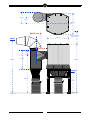
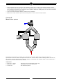
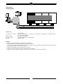
The inlet diameter of the pre-separator PSC has
been increased from Ø 600 to Ø 630 mm (ref.
chapter 1.2) (see also drawing on page 3 of this
erratum).
1. MIG/MAG solid wire (GMAW)
2. MIG/MAG flux cored wire (FCAW)
3. stick welding (MMA or SMAW)
4. TIG (GTAW) welding
5. autogenous/plasma welding
3.2
Never use a SCS in the following situations (ref.
page 3):
The SCS can be installed in different ways. The
various concepts advised by the manufacturer are
stated below.
1. arc-air gouging
2. oil mist
3. paint mist
4. heavy oil mist in welding fumes
5. hot gases (more than 40°C continuously)
6. aggressive fumes (such as acids)
7. grinding aluminium and magnesium
8. flame spraying
9. extraction of cement, saw dust, wood dust,
etc.
10. sucking cigarettes, cigars, oiled tissues and
other burning particles, objects and acids
11. in all situations where explosions car occur
•
The SCS unit is not suitable for a static pressure
over 2500 Pa (ref. page 2).
•
In contrast to the user manual, we advise against
the use of plastic bags in the drum. For this
reason plastic bags are not included (ref. chapter
2.1, 3.1, 5.1, 5.2, 7).
•
Empty both drums frequently and clean them if
necessary (ref. chapter 5.1).
•
For safety reasons the whole unit is internally
earthed. Both drum covers are prepared to apply
an earth connection to (bolt + nut M4) (ref.
chapter 3.2.2).
•
Also the air inlet and outlet ducts should be
properly earthed (ref. chapter 3.2.1).
•
Use original spare parts only (ref. chapter 5.2).
•
Please note the intermediate ring E (fig. 5.01 of
the user manual) makes contact with the springs
on the cleaning mechanism (ref. chapter 5.2)
while replacing the filters.
0507431010/ERRATUM SCS/01/00
Installation
In contrast to what is stated in the user manual, the
fan can be placed either before or behind the SCS
unit.
1.
2.
3.
4.
5.
6.
Fully controlled multiple fan system (see fig. 3.01
on page 9 of the user manual)
Uncontrolled one fan system
Semi-controlled one fan system
Fully controlled one fan system
Master-slave system
Cutting tables
The components required for each of the various
concepts are specified as of page 6.
EN - 2
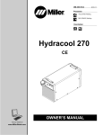
680 mm
380 mm
1200 mm
630 mm
1200 mm
AIR IN
min.free space for
service 750 mm
640 mm
250 mm
3090 mm
1100 mm
2866 mm
AIR OUT
2240 mm
1235 mm
EN - 3
0507431010/ERRATUM SCS/01/00
Recommendation installation & settings
For an optimal functioning of the SCS installation, the
manufacturer prescribes to follow the instructions
stated in the user manual and to program the
following settings.
General
In order to guarantee a maximum extraction volume,
it is necessary to clean the filter on time (see user
manual SCS, chapter 4.2 Control). During normal use
the filter will be cleaned automatically. This cleaning
is activated by the pressure difference switch that
measures the saturation of the filter. Depending on
the pre-set pressure, in other words the extraction
volume, the filter will be cleaned.
For applications with high dust quantities, (e.g.
cutting tables), you should always use the time
controlled and the off-line cleaning method (see
chapter 4.2.4 Time controlled operation). By means
of this time controlled operation it is possible to have
the filters cleaned with specific intervals during a
certain period of time.
For example: time setting from 07.00 to 17.00 h, 1
cleaning jet per 5 minutes. In combination with the
off-line cleaning method, the extraction volume will
remain at a maximum.
Off-line cleaning means filter cleaning with switched
off fan. In this way the dust particles will easier fall
down into the drum.
Next to the possibilities stated above, it is possible to
clean the filters manually (see chapter 4.2.3 Manual
operation).
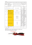
Settings SCS
Depending on the application of the SCS, the manufacturer advises the following settings:
Setting
Cutting tables
Multiple arm systems
Push-pull systems
∆P switch
1500/2000 Pa*)
(15/20 mbar)
7,5 bar
800 Pa (8 mbar) (individual fan)
1200 Pa (12 mbar) (central fan)
5-6 bar
1500 Pa (15 mbar)
07.00-17.00 h**)
1-5**)
1 pulse/5 minutes
07.00-17.00 h**)
1-5**)
1 pulse/10 minutes
07.00-17.00 h**)
1-5**)
1 pulse/10 minutes
Compressed air
pressure
Week timer/hours
Week timer/days
Time relay
5-6 bar
*)
The setting of the ∆P switch is depending on total pressure of the fan.
**)
The stated times and days of the week timer must only be regarded as an example. For these settings the
relevant week times and days should be programmed. For off-line cleaning the programmed time should be
increased by approximately 2 hours (see user manual of the week timer).
Recommendations installation SCS
•
Apart from the stated recommendations and settings,
the following matters should be checked before and
during use of the installation.
•
•
Before installing the SCS unit, check the turning
of the "shower arm" of the cleaning unit
manually; it should turn in one direction only.
•
Attention: After power breakdown or
disconnection of the power supply to the
CB-6000-MS, the week timer has a back-up time
of 24 hours.
•
During installation of the unit, check whether the
programmed times of the time controlled operation
are actually functional.
•
In case of master-slave systems, mutually
connect the ∆P switches of the units (see diagram
master-slave systems).
•
Check whether sufficient compressed air on
behalf of the filter cleaning is available during the
whole day.
•
When using fans with an overcapacity of total
pressure, arrange protection against overloading
(∆P over the filter max. 2000 Pa).
•
For off-line cleaning, check whether sufficient
compressed air is available, also after working
hours.
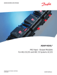
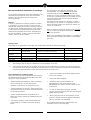
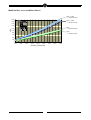
For stabilized cellulose and polyester filters: see
resistance curve on the next page.
0507431010/ERRATUM SCS/01/00
Check the condition of the filter regularly (every
three of six months).
Empty the drums regularly.
EN - 4
Modified filter curve (stabilized filters)
SCS + PSC
+ polyester filter
2000
SCS + PSC
+ cellulose filter
1800
1600
1400
SCS
+ polyester filter
P[Pa]
1200
1000
SCS
+ cellulose filter
800
600
400
200
0
1000
2000
3000
4000
5000
6000
7000
8000
9000
Extraction volume [m3/h]
EN - 5
0507431010/ERRATUM SCS/01/00
Concept 1:
Fully controlled multiple fan system
Components:
6 x SNF 4U A O 435
6 x NRV
1 x SCS1 O C 1 M 00
UltraFlex 4 + FAN 28 (400V/3ph/50Hz), incl. working light en automatic start/stop
with hood control and accessories (option)
Non-return valve
SCS with orientation 1 + Air Inlet 0° with cellulose cartridge filter, pre-separator PSC
and control box CB-SCS
For remarks concerning standard SCS installation: see user manual 3.2 Installation
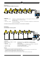
Concept 2:
Uncontrolled one fan system
Components:
6 x UltraFlex 4 + 6 x NMB + 6 x NCF
6 x WL + 1 x PP 6
6 x MD 200
1 x SCS1 O C 1 M 00
1 x FAN 110 (435)
1 x SD 7.5 + NTR
Extraction arm 4 m + wall bracket + connection flange
Working light + power supply for 6 working lights (option)
Manual damper
SCS with orientation 1 + Air Inlet 0° with cellulose cartridge filter,
pre-separator PSC and control box CB-SCS
Central fan (400V/3ph/50Hz)
Star delta switch with thermal relay
Remarks:
• Always mount a pre-separator PSC before the SCS unit.
• The manufacturer advises to mount an MD 200 in each extraction arm. In this way, the system can be
adjusted to obtain an equal extraction volume at each arm.
• The fan can be placed either before or behind the pre-separator.
• Make sure to keep sufficient space around the system in view of service and repair jobs.
0507431010/ERRATUM SCS/01/00
EN - 6
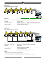
Concept 3:
Semi-controlled one fan system
Components:
6 x UltraFlex 4 + 6 x NMB + 6 x NCF Extraction arm 4 m + wall bracket + connection flange
6 x WL + AST + NCW + CB
Working light + automatic start/stop + control box
6 x MD 200
Manual damper
6 x AD 200
Automatic damper
1 x SCS1 O C 1 M 00
SCS with orientation 1 + Air Inlet 0° with cellulose cartridge filter, preseparator PSC en control box CB-SCS
1 x FAN 110 (435)
Central fan (400V/3ph/50Hz)
1 x SD 7.5 + NTR
Star delta switch with thermal relay
Concept 4:
Fully controlled one fan system
Component:
6 x UltraFlex 4 + 6 x NMB + 6 x NCF Extraction arm 4 m + wall bracket + connection flange
6 x WL + AST + NCW + CB
Working light + automatic start/stop + control box CB
6 x MD 200
Manual damper
6 x AD 200
Automatic damper
1 x SCS1 O C 1 M 00
SCS with orientation 1 + Air Inlet 0° with cellulose cartridge filter, preseparator PSC en control box CB-SCS
1 x FAN 110 (435)
Central fan (400V/3ph/50Hz)
1 x IF 15
Interface between workplace and frequency control
1 x FREQ 110
Frequency control (non-Euromate product)
Remarks:
• Always mount a pre-separator PSC before the SCS unit.
• Mount the AD 200 between the extraction arm and the central ductwork.
• When using a frequency control, an AD 200, an AST, a CB and an IF 15 are required as well.
EN - 7
0507431010/ERRATUM SCS/01/00
•
•
•
During operation time of this system, the frequency control has to be set in the stand-by position. When a
valve is opened automatically due to the start of welding activity, the frequency control will switch on the fan,
thus creating an airstream at the extraction arm in question. When the welding stops, the fan will be switched
off automatically after a certain period.
The fan can be placed either before or behind the pre-separator.
Make sure to keep sufficient space around the system in view of service and repair jobs.
Concept 5:
Master-slave system
The SCS can be connected in parallel with a maximum of four units. Make sure to install the ductwork
symmetrical in order to achieve an equal load at each unit. In such cases, the filter cleaning will be controlled by
the "master" unit (see electrical and pneumatic diagram). This means that one SCS needs to be provided with a
CB-SCS and the other units without ("slaves").
Components:
1 x SCS1 O C 1 M 00
1 x SCS1 O C 1 S 00
1 x central fan
SCS with control box CB-SCS (master unit)
SCS without control box (slave unit)
Non-Euromate product
0507431010/ERRATUM SCS/01/00
EN - 8
Concept 6:
Cutting tables
Components:
1 x SCS1 O C 1 M 00
FAN 90 (435)
SD 7.5 + NTR
MD 400
Cutting table
SCS with orientation 1 + Air Inlet 0° with cellulose cartridge filter, pre-separator PSC
and control box CB-SCS
Fan (400V/3ph/50Hz)
Start delta switch with thermal relay
Manual damper
Remarks:
• Always mount a pre-separator PSC before the SCS unit.
• Mount the MD 400 between the duct and the pre-separator.
• Throttle the air volume during the first 25 operation hours, so that the filter gets polluted gradually, After these
25 hours the damper can be opened entirely.
• Repeat this procedure after replacement of the filters.
• The fan can be placed either before or behind the pre-separator.
• Make sure to keep sufficient space around the system in view of service and repair jobs.
EN - 9
0507431010/ERRATUM SCS/01/00
0507431010/ERRATUM SCS/01/00
EN - 10
Euromate B.V.
Wezelkoog 11, 1822 BL Alkmaar
P.O. Box 9350, 1800 GJ Alkmaar
Holland
Art. no. 0507431010
Version 01/00


![RS8CH422 AK2 IO [w-AKC 55] User Manual](http://vs1.manualzilla.com/store/data/005784090_1-938eac098068c47f936e9b0d54a0884d-150x150.png)