1
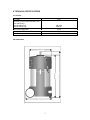
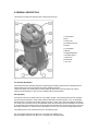
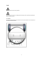
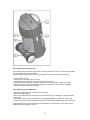
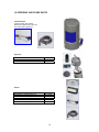
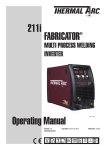
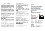
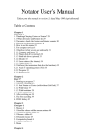
FumeClean 230
Portable high vacuum welding fume extractor
Product no 196-735878
Instructions for use
CONTENTS:
Page
1 IDENTIFICATION OF THE PRODUCT
2
2 SAFETY INSTRUCTIONS AND WARNINGS
3
3 USED PRODUCTS AND THE ENVIRONMENT
4
4 TECHNICAL SPECIFICATIONS
5
5 GENERAL DESCRIPTION
7
6 INSTALLATION
8
7 USE
9
8 MAINTENANCE
11
9 TROUBLESHOOTING
13
10 ORDERING AND SPARE PARTS
14
1
1 IDENTIFICATION OF THE PRODUCT
The identification plate (see fig. 1) contains the following data:
A serial number
B product name
C max. power (speed setting ‘high’)
D supply voltage and frequency
2
2 SAFETY INSTRUCTIONS AND WARNINGS
General
The manufacturer does not accept any liability for damage to the product or personal injury caused by nonobservance of the safety instructions in this manual, or by negligence during installation, use, maintenance
and repair of the product mentioned on the cover of this document and any corresponding accessories.
Specific working conditions or used accessories may require additional safety instructions. Immediately
contact your supplier if you detect a potential danger when using the product.
The user of the product is always fully responsible for observing the local safety
instructions and regulations. Observe all applicable safety instructions and regulations.
User manual
• Everyone working on or with the product must be familiar with the contents of this manual and must strictly
observe the instructions therein. Management should instruct their personnel in accordance with the
manual and they must observe all instructions and directions given.
• Never change the order of the steps to perform.
• Always keep the manual with the product.
Intended use 1)
The product has been designed exclusively for extracting harmful fumes and gases that are released during
the most common light and medium welding processes. Using the product for other purposes is considered
contrary to its intended use. The manufacturer accepts no liability for any damage or injury resulting from
such use. The product has been built in accordance with state-of-the-art standards and recognized safety
regulations. Only use the product in technically perfect condition in accordance with its intended use and the
instructions laid down in the user manual.
1) "Intended use" as laid down in EN-292-1 is the use for which the technical product is suited as specified by the manufacturer, inclusive of
his directions in the sales brochure. In case of doubt it is the use which can be deducted from the construction, the model and the function
of the technical product which is considered normal use. Operating the machine within the limits of its intended use also involves observing
the instructions in the user manual.
WARNING
Fire hazard! Never use the product for extracting inflammable, glowing or burning particles or solids or
liquids. Never use the product for extracting aggressive fumes (such as hydrochloric acid). The product may
be used for extracting and/or filtering fumes and gases that are released during the following welding
processes:
• MIG/MAG solid wire (GMAW)
• MIG/MAG flux cored wire (FCAW)
• Stick welding (MMA or SMAW)
• TIG (GTAW) welding
Welding class “W3”:
The product is suitable for the extraction of fume from metals that have a nickel and chrome (for example)
content over 30%.
Never use the product for extracting and/or filtering fumes and gases which are released during the following
(welding) processes:
• MIG/MAG welding robots with intensive use of TipDip or other anti-spatter products
• autogenic or plasma cutting
• arc-air gouging
• (welding with) a release of a dense oil mist
• paint spraying
• extraction of hot gases (more than 40°C continuously)
• extraction of aggressive fumes (such as acids)
3
• grinding aluminium and magnesium
• thermal spraying (i.e. plasma etc.)
• extraction of cement, saw dust, wood dust, etc.
• sucking cigarettes, cigars, tissues and other burning particles, objects and acids
• any dangerous situations in which there is a risk of an explosion or fire
WARNING
Never reach into the intake or outlet of the fan.
Modifications
Modification of the product or any of its parts is not allowed.
3 USED PRODUCTS AND THE ENVIRONMENT
PACKAGING MATERIAL
The purpose of the packaging is to protect the product during transport. It consists of the following
substances which can be reused: - polyethylene foil - corrugated cardboard Do not dispose of the packaging
material as industrial waste, but ask your municipal sanitation department where to dispose of the material.
4
4 TECHNICAL SPECIFICATIONS
4.1 General
Net weight
16 kg
Extraction volume (clean filter with 2,5 m
hose and EN 20):
• speed setting ‘low’
• speed setting ‘high’
Filter surface main filter
Filter surface HEPA filter
Filter efficiency
140 m3/h
230m3/h
12 m2
0,4 m2
99,9% (incl.HEPA filter H12)
4.2 Dimensions
5
4.3 Electric system
See the identification plate (fig 1) and the separate electrical diagram.
Power consumption:
• speed setting ‘low’: ±70%
• speed setting ‘high’: 100%
4.4 Ambient conditions
5°C
40°C
80 %
50
Min. operating temperature
Max. operating temperature
Max. relative humidity
IP class
4.5 Sound pressure
The level of the A-weighed sound pressure is 70 dB(A) according to ISO 3746. Measurements performed in
the workshop with a PHV fitted with a welding torch.
6
5 GENERAL DESCRIPTION
The machine consists of the following main components (see fig. 3)
A control panel
B fans
C mains cord
D air intake Ø 48 mm
E bottom
F pre-separator
G wheels
H integrated prefilter
I main filter Dura-H
J outlet cover
K HEPA filter
L top cover
5.1 General description
The machine has been specially designed for extracting and/or filtering harmful fumes and gases that are
released during the most common light and medium welding processes.
With its the wheels, the handle and its compact design the machine is extremely suited to be used in
relatively small workshops or near sources of pollution without a fixed location.
5.2 Operation
The machine works in accordance with the re-circulation principle. The extracted fumes pass the air intake
and enter the pre-separator in which primary filtration takes place and where sparks, if any, are separated.
Subsequently the air passes the pre-filter and the main filter, in which most of the fume particles are filtered
out. Finally, the fan blows the air into the HEPA filter where the remaining fumes are separated. The cleaned
air is returned into the workshop via the outlet grid. With the optional hose connection HCH 45 the air can be
discharged elsewhere, for example into the atmosphere, such as is the case when welding stainless steel.
The welding fumes can be extracted at source in the following ways:
A by the supplied extraction hose Ø 45 mm connected to the welding torch
B by the supplied extraction hose Ø 45 mm connected to the extraction nozzle
7
6 INSTALLATION
6.1 Unpacking
Check that the machine is complete. The package should contain:
• portable welding fume extractor
• extraction hose 2,5 m/Ø 45 mm
• 4 carbon brushes
• user manual
• electrical diagram
6.2 Installation
The machine is ready for use.
CAUTION!
Do not position the machine in places where it is exposed to vibrations or radiation from heat sources.
Observe the ambient conditions as described in chapter 4.4.
6.3 Connection to the mains
CAUTION!
Make certain that the machine can be connected to the local mains. Specifications with respect to supply
voltage and frequency can be found on the identification plate.
8
7 USE
CAUTION!
Before use carefully read the safety regulations.
WARNING
It is required that the product is in an upright position and that the inlet is closed when transporting the
product over larger distances.
7.1 Controls
.
The required under-pressure will not be achieved in the 'low' mode of operation. As a consequence, the
warning signal will not be activated.
9
The control panel (see fig. 4) contains the following controls:
A Button: on/off; low/high
Button for switching the machine on and off and for switching from ‘low’ to ‘high’ motor speed and vice
versa.
B Button manual/auto
Button for switching the machine from automatic on/off to manual control and vice versa.
C Button: reset (optionally)
Button to reset the filter pollution indicator.
D Slit mass cable; automatic start/stop
Slit for inserting the mass cable of the welding machine; this activates the arc sensor for automatic on/off
switching of the extractor. Min. current 50 Amps.
E On/off switch (USA/Canada)
Switch for switching the machine on and. When this switch is installed, button A's on/off function becomes
obsolete.
7.2 Use
7.2.1 PHV with welding torch + integrated extraction
Before use, carefully read the user manual of the welding torch.
• Connect the extraction hose Ø 45 mm at one side to the air intake of the machine and at the other side to
the welding torch.
• Put the mass cable of the welding machine into the slit on top of the machine.
• Start up the machine by pressing the on/off button. Preferably use the automatic start/stop device (‘auto’)
to extend the life of the carbon brushes.
• The machine continues to run for 15 seconds (in the 'auto' setting) after welding is completed.
7.2.2 PHV with extraction nozzle
The machine can be supplied with two types of extraction nozzles:
- funnel nozzle with magnetic foot (EN 20) for various welding processes/situations;
- slit extraction nozzle with magnetic foot (EN 40) for horizontal welding activities, such as stick welding.
It is recommended that the extraction nozzle EN 20 is positioned above the welding spot (when possible) to
achieve optimum welding fume extraction.
• Place the extraction nozzle at 2-4 cm from the source of pollution.
• Insert the mass cable of the welding machine into the slit on top of the extractor.
• Start up the machine by pressing the on/off button. Preferably use the automatic start/stop device (‘auto’)
to extend the life of the carbon brushes.
• The machine continues to run for 15 seconds (in the 'auto' setting) after welding is completed.
.
When using the machine, regularly check that the extraction capacity is sufficient. When the extraction
capacity decreases, the filters should be replaced. Decrease of extraction capacity may lead to a too high
concentration of harmful welding fumes in the workshop. When the machine is provided with a filter pollution
indicator (option), there will be acoustic and optical signals when the extraction capacity is too low.
10
8 MAINTENANCE
The machine has been designed to function without problems for a long time with a minimum of
maintenance.
In order to guarantee this some simple, regular maintenance and cleaning activities are required which are
described in this chapter.
If you observe the necessary caution and carry out the maintenance at regular intervals, any problems
occurring will be detected and corrected before they lead to a total standstill of the machine.
The indicated maintenance intervals can vary depending on the specific working and ambient conditions.
Therefore it is recommended to thoroughly inspect the complete machine once every year in addition to the
indicated periodic maintenance.
Please contact your supplier for this inspection.
PHV-I only; Germany-specific: Inspection and maintenance in accordance with TRGS 560 (W2 and W3):
Inspection and maintenance of the product shall be carried out in conformance with TRGS 560, chapter 5,
paragraph 9.
WARNING!
Overdue maintenance may cause a fire.
WARNING!
Always switch the machine OFF and remove the mains plug from the wall socket before carrying out the
activities below. First read the maintenance regulations at the beginning of this manual.
8.1 Periodic maintenance
The maintenance activities in the table below indicated by [1] can be carried out by the user; other activities
shall only be carried out by qualified personnel.
8.2 Replacing the filters
The main filter and the HEPA filter cannot be cleaned and therefore they have to be replaced periodically.
WARNING!
A saturated filter often contains dust and dirt particles which could form a health hazard upon inhalation.
When replacing the filters always wear a high-quality and approved face mask.
Wrap the filters in a properly closed plastic bag and dispose of it in compliance with the local regulations. It
is not allowed to empty the filters using air or by tapping.
Replace the filters in case of damage or when the extraction capacity has become insufficient due to the
amount of pollution materials in the filter.
One must learn from experience when to replace the filters, since the life of the filters strongly depends on
the composition of the welding fumes, the humidity, etc.
Proceed as follows (see fig. 5):
11
8.2.1 Replacement of the main filter
Use the plastic bag that contains the new filter to exchange the filter for a new one. Draw the bag carefully
over the old filter when removing the filter.
After that close the bag with a tie wrap. The pre-separator can also be emptied in the same bag.
• Loosen the side clips (A).
• Remove the top cover (B) from the machine.
• Carefully remove the main filter (C) from the bottom of the machine.
• Check the seals before placing a new filter. If the seals need to be replaced, contact your supplier.
• Place the new filter and mount the disassembled parts in reverse order. Check that the integrated
aluminium pre-filter is placed at the bottom.
8.2.2 Replacement of the HEPA filter
• Remove the outlet cover by loosening the two screws (D)
• Remove the HEPA filter (E).
• Place a new HEPA filter in the correct position (open side at the top); to facilitate this, apply some suds
to the seals.
• Remount the outlet cover by fastening the two screws. Make sure that the outlet cover is in the right
position; the open side of the HEPA filter should correspond with the smallest opening of the outlet cover.
ATTENTION: By taking out the HEPA filter, its seals will deform. For this reason, never replace a used
HEPA filter, but always place a new one.
12
9 TROUBLESHOOTING
If the machine does not function (correctly), please consult the checklist below to see if you may remedy
the error yourself. If not, please contact your supplier.
WARNING!
Always switch OFF the machine and remove the mains plug from the wall socket before carrying out any
repairs.
The repair activities in the table below indicated by [1] can be carried out by the user; other activities shall
only be carried out by qualified personnel.
Always replace all motor seals when replacing or carrying out maintenance on the motors.
If the supply cord is damaged, it must be replaced by the manufacturer or its service agents or a similarily
qualified person in order to avoid hazard.
Problem
Motor does not start.
Extraction capacity
insufficient.
Motor stops
automatically.
Possible cause
No mains voltage.
Supply cord defective.
Carbon brushes worn.
Motor defective.
Main filter polluted.
Solution
Check the mains voltage.
Repair or replace the supply cord.
Replace the carbon brushes.
Replace both motors.
Replace both main filter and HEPA
filter [1].
Extraction hose damaged or leak. Replace the extraction hose [1].
Seals damaged or leaking.
Replace the seals.
Thermal protection is activated.
Check that the cooling slits
underneath the top cover and/or
the outlet are not obstructed.
Dust or smoke coming Filter torn or placed incorrectly.
out of the outlet grid.
13
Replace the filter or position it
correctly [1].
10 ORDERING AND SPARE PARTS
FumeClean 230
Product number 196 735878
Delivered complete with 2,5m hose
and nozzle with magnet foot
Optionals
Bulkhead bracket
Hose connection, outlet side
Active carbon filter
196 740399
196 740381
196 740431
Spares
Disposable Cartridge Filter
High Efficiency Particle Filter H12
Funnel Nozzle With Magnetic Foot
Extract/Exhaust Hose 2,5 M, Ø 45mm
Connection Piece For Two Hoses Ø 45mm
Carbon Brushes 2 Sets W.Seals 230V
196 740415
196 740423
196 740373
196 740449
196 740456
196 740407
14
Unitor ASA
Mail: P.O. Box 300 Skøyen, N-0213 Oslo, Norway.
Office: Drammensvn. 175, N-0277 Oslo, Norway.
Tel: +47 22 13 14 15, Fax: +47 22 13 45 00
Tlx: 76004 UNITOR N
www.unitor.com
15