1
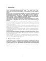
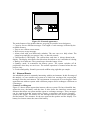
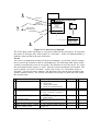
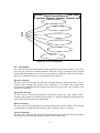
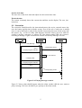
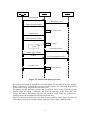
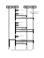
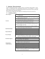
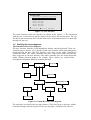
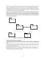
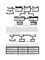
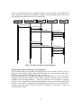
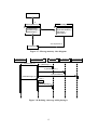
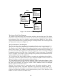
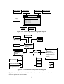
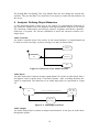
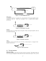
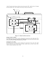
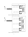
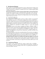
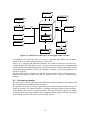
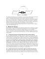
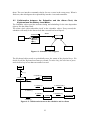
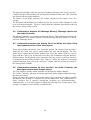
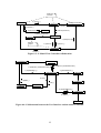
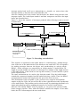
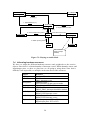
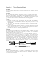
Digital Sound Recorder: A case
study on designing embedded
systems using the UML notation.
Ivan Porres Paltor
Åbo Akademi University, Department of Computer Science,
Lemminkäisenkatu 14, FIN-20520 Turku, Finland
email: [email protected]
Johan Lilius
Åbo Akademi University, Department of Computer Science,
Lemminkäisenkatu 14, FIN-20520 Turku, Finland
email: [email protected]
Turku Centre for Computer Science
TUCS Technical Report No 234
January 1999
ISBN 952-12-0367-6
ISSN 1239-1891
Abstract
This document is an example of the object-oriented analysis and design of
an embedded system using the Unified Modelling Language (UML). The
analysed system is a digital sound recorder, or Dictaphone. The design has
been implemented using an embedded processor and the C++ programming
language.
Keywords: object-oriented design, UML, embedded systems.
TUCS Research Group
Programming Methodology Research Group
1 Introduction
The Unified Modelling Language [BJR1, BJR2], provides a standardised notation to
express object-oriented software analysis and design [CY90, MO92, SS95]. UML
diagrams are able to model complex software systems including real-time embedded
systems.
However, UML is not a software process. UML does not specify the different stages of
the development of a software project. The UML standard specifies a notation for
several different diagrams, but it does not describe how to create and apply each
diagram. [Dou98] presents a methodology for building embedded systems using the
UML notation and object-oriented analysis and design techniques.
This document describes the object-oriented design and implementation of a digital
sound recorder, or Dictaphone, using the UML notation and the method described by
Douglass.
There are several digital sound recorders commercially available in the market. The
model described here has been designed following the specifications of a commercial
product from a well know manufacturer. These requirements are described in the second
section of this document.
The third section discusses the object model of the system and presents the main class
diagram. The fourth section continues the object-oriented analysis but focusing in th
internal behaviour of each object.
The fifth section deals with the architectural design. We show the hardware architectur
of the sound recorder and the concurrency model, where we assign each object to an
execution thread.
The design continues defining the collaborations between the different objects. This is
done in section number six, where design patterns [GHJV95] are used to glue together
the classes defined in the analysis phase. The most specific design issues are discussed
in the section number seven.
Finally, The eighth section discusses the implementation. We have implemented th
software in the C++ programming language and built the hardware platform to run the
code using a 32 bits RISC embedded processor.
1.
2.
2 Requirements Analysis
A digital sound recorder is a consumer electronic appliance designed to record and play
back speech. The messages are recorded using a built-in microphone and they are stored
in a digital memory. The user can quickly play back any message at any moment trough
a speaker placed in the front of the device. It should be small, light, easy to use, and
battery operated.
Figure 2.1 shows what our sound recorder could look like. It is a hand held unit with
flat display and fairly large buttons.
1
Yes
No
Figure 2.1: External appearance
The main features of the product that we are going to consider in our design are:
• Capacity for ten different messages. The length of each message is limited by the
available memory.
• Easy to use with on screen menus.
• Direct access to any message.
• Alarm clock with year-2000-ready calendar. The user can set a daily alarm. The
alarm beeps until the user presses a key, or after 60 seconds.
• Full Function LCD Display. The current date and time is always shown in the
display. The display also shows clear directions about how to use it and what it is doing.
• Battery-level indicator. The system beeps when the battery is low.
• Stand-by mode. It economises the battery power. The system switches off th
peripherals when they are not in use. The normal operation is resumed when the user
presses a key.
• Good sound quality. Sound is processed at 6Khz using eight bits per sample.
2.1 External Events
An embedded system is constantly interacting with its environment. In this first stage of
the analysis, we can consider our system as a black box reacting to the requests and
messages from the environment. The environment is composed of several agents. Each
agent interacts with our system with a different purpose and it exchanges a different set
of messages.
Context-Level Diagram
Figure 2.2 shows all the agents that interact with our system. We have identified thre
agents: the user, the battery and the time. It also shows the interfaces, sensors and
actuators that allow our system and the agents to exchange messages. These messages
can be requests from the agents to the system, or responses and services from the
system to the agents. The sensors for the messages from the user are the microphone
and the buttons. The actuators for the user agent are the speaker and the display. The
battery level meter senses the state of the battery.
2
Time
next second
Digital Sound Recorder
Sensors/Actuators
Record
message, set
alarm, set time
User
+Buttons
+Microphone
+Screen
+Speaker
+Battery Level Meter
Play message,
beep alarm, show
time
System
Power
Interfaces
-Analog To Digital
-Digital To Analog
-Digitral to Digital
Battery
Figure 2.2: Context-Level diagram
The Time agent sends a message to our system whenever the time passes. It represents
the source of messages like “next second” or “next hour”. In the real implementation, a
hardware timer measures the pass of the time.
Events
An event is an important message from the environment. A real-time reactive system
has to react to the external events in a bounded time. The following table shows all the
external events that can occur in our system. The direction of an event can be “In”, from
the environment to the system, or “Out”, from the system towards the environment. The
arrival pattern (A) can be Periodic, if the event occurs on a fixed time basis, or
Episodic, if its arrival time is random. The Response time sets an upper bound for the
system response actions. The system will behave incorrectly if it does not react within
the response time.
Event
1 A second passes
2 A sample period passes
3 User presses a command button
4 User presses the “stop” button
5 Low battery alarm
6 Enter stand-by mode
7 Wake up, user presses a button
while in stand-by mode.
System Response
a. Update internal clock
b. Check alarm
c. Update clock display,
d. Update task progress display.
a. Play or record next sample
a. Show task progress display
b. Start recording or playing a
message
a. Current task is stopped
b. Update display
a. Warn the user and stop current
task
a. Switch off the display
a. Leave stand-by mode, power up
display, etc.
3
Direction
In
A Resp.
P 0.5 s
In
In
P ½ period
E 0.5 s
In
E 0.5 s
In
E 1 s.
In
In
E 1 s.
E 1 s.
Digital Sound Recorder
Record a message
Playback message
Delete message
User
Set alarm time
Set clock time
Watch time
Figure 2.3: Use Case diagram
2.2 Use Cases
Use cases describe the functionality of the system from the user’s point of view. The
user may be a person or another machine. Each use case is a different way to use the
system and the completion of each use case produces a different result. In our system
there are six different use cases, represented in the Figure 2.3.
Record a message
The user selects a message slot from the message directory and presses the ‘record’
button. If the message slot already stores a message, it is deleted. The system starts
recording the sound from the microphone until the user presses the ‘stop’ button, or the
memory is exhausted.
Playback a message
The user selects a recorded message slot and then presses the ‘play’ button. If th
message slot contains a recorded message then it is played trough the speaker until its
end or until the user presses the stop button.
Delete a message
The user selects a used message slot and then presses the ‘delete’ button. The message
is permanently deleted from the memory and its memory space is recycled.
Set the alarm time
The user can switch on and off the alarm and set the time when the alarm will sound.
This is done by selecting the different options of the alarm menu.
4
Set the clock time
The user can set the clock time and adjust it to the current time zone.
Watch the time
The system constantly shows the current time and date on the display. The user just
looks at it.
2.3 Scenarios
The scenarios should describe the interaction between the active external actors (the
user, the battery and the time) with the system. Even if the role of each actor is usually
clear, it can be difficult to study all the possible interactions between all the actors and
the system. E.g., we have to study what happens when the battery goes low while th
system is playing a message, or what to do if the alarm sounds while the system is
recording a message. Figure 2.4 shows an scenario for the Play Message use case.
<< actor >>
User
: System
:Speaker
1: Play Message
2: Start playing sound
{0.5 s.}
3: Display Progress Indicator
4: Next Second
{ 0.5 s. }
5: Display Clock
6: Display Progress Indicator
7: Stop
{0.5 s.}
8: Stop playing sound
Figure 2.4: Playing message scenario
Figure 2.5 shows what should happen when the alarm sounds while the user wants to
play a message. We have decided to give priority to the alarm sound.
5
<< actor >>
User
: System
:Speaker
1: Play Message
2: Start playing sound
3: Display Progress Indicator
4: Next Second
5: Display Clock
6: Display Progress Indicator
7: Alarm!
{ 0.5 s}
8: Start playing alarm
9: Display Alarm Indicator
10: Stop
11: Stop playing alarm sound
13: Display Cock
12: Next Second
Figure 2.5: Alarm while playing scenario
The system can switch on and off the screen backlight, the microphone and the speaker.
These elements use a considerable amount of battery power. By switching them off the
system saves energy and increases the battery life.
The battery can also warn the system when it is almost out of energy. Then the system
should switch off all the peripherals and enter the stand-by mode. When the user
charges the battery, the system will leave the stand-by mode. While the system is in
stand-by mode, the messages are still kept in the memory.
Figure 2.6 shows a scenario where the system enters stand-by mode, then it is woken up
by the alarm clock. After another battery warning, it enters again stand-by mode.
6
: Battery
: System
: Display
:Speaker
1: Next second
After some minutes
without any activity
2: Next Second
3: Switch off display
4: Switch off amplifier
5: Next second
6: Alarm !
7: Switch on display
8: Switch on amplifier
9: Start playing alarm sound
10: Next second
11: No Power!
12: Stop playing alarm sound
13: Switch off amplifier
14: Switch off display
Figure 2.6: Entering and exiting stand-by mode scenario
3.
7
3 Analysis: Object structure
After the requirement analysis, [SS95] proposes the Domain Analysis phase. In this
phase, we should analyse the requirements and present a class diagram as a general
solution for the problem. The domain diagram shows the main classes of the system and
their relations, but it omits their interface.
The first step in building the class diagram is identifying the objects involved in it.
3.1 Identifying objects
Message Player & Recorder
Active Objects
A “digital tape”.
Buttons, Screen
The user can press the buttons. The screen shows a menu
and indications to the user.
Alarm Clock
It shows the time and it can wake up the user
Battery
level sensor
Services
Measures the remaining battery power level
Analogue to digital converter
The interface between the microphone and the processor
Digital to analogue converter
The interface between the processor and the microphone
Screen controller
Generates the image on the LCD screen
Date
Real-World Items
Time
Speech, Sound
Microphone, Speaker
Physical Devices
Battery
Keyboard, Display
Speech, Sampling, Sound sample
Key Concepts
We must study how a discrete digital system can capture
and process an analogue and continuos sound signal.
Sound message
Collection of recorded messages
Persistent objects
The contents of the digital tape
Current Time, Date
Alarm Time
When to warn or wake up the user
Message
Transactions
Menu, Menu option, Menu selection
Visual elements
Clock, Alarm on/off indicator
Calendar
Status bar, help line, Task progress indicator
Play , Record, Stop, Yes, No, Up, Down, Left, Right Buttons
The user interacts with the system by pressing the buttons.
There are nine different buttons
8
10:23:45
10 August 1998
08:00
Message Menu:
Recorded at 09:23 10.08.1998
xRecorded at 12:45 05.07.1998x
Empty message
Empty message
Empty message
Empty message
Empty message
Stop. Press
to play message.
Figure 3.1: User Interface
The visual elements of the user interface are shown in the Figure 3.1. The interaction
with the user is menu-driven and the display always shows the current menu. The top
line shows the current time, date and the alarm time. At the bottom, there is a short help
message for the user.
3.2 Building the class diagrams
The Sound Recorder Class Diagram
The user interacts with the system through the display and the keyboard. These are
somehow passive objects, so we decide to add a user interface object that manages the
interaction with the user. The User Interface class relies on the Audio Controller to
perform the tasks. The Audio Controller is the core of the system and it executes the
tasks suggested by the user interface. The audio controller uses the Audio Input and
Audio Output classes to produce the sounds. These classes are related with a
microphone and speaker hardware wrapper [AKZ96]
Keyboard
UserInterface
Display
Battery
AlarmClock
AudioController
MessageMemory
1
AudioInput
AudioOutput
Microphone
Speaker
10
Message
Figure 3.2: Sound Recorder class diagram
The messages are stored in the message memory. This class keeps a directory with th
recorded messages, allocates spaces for the new messages, and deletes the old ones.
9
The Alarm Clock updates the internal clock and checks when to sound the alarm. In this
case, it notifies the event to the User interface, so the User interface can show an
indication on the display and play an alarm sound with the help of the Audio Controller.
The Battery object periodically measures the battery power level. When the battery goes
low then it reports the event to the User Interface.
Figure 3.2 represents graphically the main classes of the digital sound recorder. The
class diagrams provide a general overview of the whole system by abstracting from the
details of each class. We have divided the class diagram into five different subsystems:
the alarm clock, the battery, the user interface, the memory and the audio subsystem.
This division is represented in Figure 3.3. The following sections study and develop
each subsystem a bit further.
<<subsystem>>
Alarm Clock
<<subsystem>>
User Interface
<<subsystem>>
Memory
<<subsystem>>
Battery
<<subsystem>>
Audio
Figure 3.3: Subsystems in the sound recorder
The Audio Subsystem Class Diagram
Each message is composed of several audio blocks and each audio block if composed of
many sound samples. The Audio subsystem always records or plays a complete audio
block.
The Audio Input and Audio Output classes have real-time requirements. The Timer
class provides accurate timing for the Audio Input and Output classes. The timer class is
a wrapper for a hardware timer.
The Microphone class is a hardware wrapper for the physical microphone. A
Microphone class can record one sound sample. The Speaker class is able to play back
sound sample through the hardware speaker.
10
AudioController
Message
Synthesiser
AudioBlock
getSample( )
addSample( )
playMessage( )
recordMessage( )
deleteMessage( )
playAlarm( )
stop( )
getAudioBlock( )
appendAudioBlock( )
getHeader( )
setHeader( )
0..*
buildAudioBlock( )
playNote( )
playChord( )
silence( )
CompressedAudioBlock
AudioOutput
AudioInput
Timer
playCompressedAudioBlock( )
playAudioBlock( )
selectOutputFilter( )
recordCompressedAudioBlock( )
selectInputFilter( )
Microphone
Speaker
getSample( )
playSample( )
Figure 3.4: Audio subsystem class diagram
Why do we need three different classes to play a message? Playing or recording a
message is a complex task that requires a precise timing and interaction with the
hardware. We also believe that by splitting the representation of the messages from their
process we increase the flexibility of the design. This design can be easily extended to
stereo messages with two channels of audio blocks or pipelined compression, where the
sound is compressed while it is recorded.
is a sequence of
Message
AudioBlock
is a sequence of *
0..*
plays
AudioController
SoundSample
*
plays
AudioOutput
plays
Speaker
Figure 3.5: Internal representation of sound messages
Figure 3.5 shows the decomposition of a message into audio blocks and sound samples.
It also shows what class is responsible to play each element.
Granularity
Sound sample
1/6000th of second
AudioBlock
2000 samples, 1/3 th of second
Message (variable length)
E.g. 60 AudioBlocks, 20 s.
Play
Speaker
.playSample()
AudioOutput
.playAudioBlock()
AudioController
.playMessage
11
Record
Microphone.
.recordSample()
AudioInput
.recordAudioBlock()
AudioController
.recordMessage()
Figure 3.6 shows the messages exchanged in order to play a message. This diagram has
been simplified to improve its readability. Actually, an AudioOutput object will invoke
the playSample method 2000 times per audio block.
: UserInterface
: AudioController
: Message
: AudioOutput
: Speaker
1: playMessage ( )
2: getAudioBlock ( )
3: playCompressedAudioBlock ( )
4: playSample ( )
5: playSample ( )
6: playSample ( )
7: getAudioBlock ( )
8: playCompressedAudioBlock ( )
9: playSample ( )
10: playSample ( )
11: playSample ( )
Figure 3.6: Play message sequence diagram
The Message Memory Subsystem Class Diagram
The message memory class manages the storage space of the sound recorder, it keeps a
directory of recorded messages and it allocates space for new messages. The class
diagram for the memory subsystem is shown in Figure 3.7
The User Interface uses the Message Memory for obtaining the list of recorded
messages, but it does not modify it. The Audio Controller is the only class that uses the
modifiers of the Message Memory. If the User Interface wants to delete a message,
instead of accessing directly to the Message Memory object, it uses the deleteMessage
method of the Audio Controller. This mechanism prevents the User Interface from
deleting a message while the Audio Controller is playing or recording it. Figure 3.8
represents this scenario.
12
AudioController
1
MessageMemory
Message
newMessage( )
deleteMessage( )
getMessage( )
10
*
AudioBlock
getAudioBlock( )
appendAudioBlock( )
getHeader( )
setHeader( )
is a sequence of
0..*
Figure 3.7: Message memory class diagram
: UserInterface
: AudioController
1: playMessage ( X )
: Message
Memory
X : Message
2: getMessage ( )
3: getAudioBlock ( )
4: playAudioBlock ( )
5: deleteMessage ( X )
6: stop ( )
7: deleteMessage ( )
Figure 3.8: Deleting a message while playing it
13
: AudioOutput
Time
Now
get( )
set( )
nextSecond( )
cycleHour( )
cycleMinute( )
AlarmClock
getTime( )
getDate( )
getAlarm( )
getAlarmState( )
setAlarmState( )
AlarmTime
Date
get( )
set( )
nextDay( )
cycleDay( )
cycleMonth( )
cycleYear( )
Today
Figure 3.9: Alarm clock class diagram
The Alarm Clock Class Diagram
The Alarm Clock class keeps the current time and date and the alarm time. The Alarm
Clock uses a timer to measure the pass of the time. Each second updates the internal
representation of the time, by using the nextSecond method. When the Time object
wraps around, then the date is updated using the nextDay method. The class diagram for
the Alarm clock is shown in Figure 3.9.
The User Interface Class Diagram
The User Interface class manages the interaction with the user. It receives the input
from the user trough a keyboard and gives feedback to him or her trough a display.
The Display class is the interface to the hardware display. It can be switched on or off in
order to save energy. The Graphic Context abstraction is used to draw on a Display. It
provides some basic drawing primitives like drawing points, lines, text strings or filling
rectangular regions with a flat colour. Each Graphic Context represents a rectangular
area of a Display. The Graphic Context manages the geometry transformation from its
local coordinate system to the global one.
The View classes use these graphic primitives to render the application objects like th
current time or the user menu. Each View uses a different Graphic Context to draw on.
Figure 3.10 shows a visual representation of these objects.
The User Interface also receives messages from the Alarm Clock and the Battery. Some
events, like when the battery goes low, are modeless; that is, the system always reacts in
the same way whenever the event is present. These modeless events are managed
directly by the User Interface object.
However, the system reacts to some other events, like when pressing a button,
depending on the current User Mode. When the user presses the “down” button, th
system can select the next option in a menu or it can decrease the current time. These
events are called modal, and they are forwarded from the ‘generic’ User Interface event
handler to a more concrete User Mode class.
14
TimeCV:ClockView
:GraphicContex
:Display
10:23:45
:GraphicContex
10 August 1998
AlarmCV:ClockView
08:00
Message Menu:
Recorded at 09:23 10.08.1998
xRecorded at 12:45 05.07.1998x
Empty message
Empty message
Empty message
Empty message
Empty message
:MenuView
:GraphicContex
Figure 3.10: Visual representation of graphic objects.
AudioController
Keyboard
Battery
getLastKey( )
getLevel( )
UserInterface
AlarmClock
setUserMode( )
Alarm!( )
GraphicContext
UserMode
View
activate( )
deactivate( )
update( )
1..*
update( )
1..*
1
drawLine( )
drawPoint( )
drawText( )
foregroundColor( )
backgroundColor( )
font( )
clear( )
setViewport( )
ClockView
MenuUserMode
TaskView
Display
SettingTimeUserMode
MenuView
SettingDateUserMode
On( )
Off( )
Figure 3.11: User interface subsystem class diagram
The Menu User Mode class and the Menu View class can allow the user to choose from
different options on a screen menu.
15
The Setting Date and Setting Time User Modes allow the user change the current date
and time. They use the Date View and Time View objects to render the date and time on
the screen.
4.
4 Analysis: Defining Object Behaviour
A class diagram presents a static view of our system. To understand the behaviour of
our system we should create new diagrams showing the dynamic aspects of our design.
The statechart, collaboration and message sequence diagrams describe the dynamic
behaviour of a system. We will use statecharts to shows the internal evolution of a
single object.
Audio Controlle
An Audio Controller object is the referee for the sound channels. A sound channel can
be used to record a message, to play a message or to play an alarm sound.
Playing
Recording
Idle
Alarm
Figure 4.1: Behaviour of an AudioController
Audio Input
An audio input object controls an input sound channel. It records an audio block from a
microphone object with the help of an DMA channel. After recording the block the
sound is compressed. The behaviour of an Audio input object is represented in Figure
4.2.
Idle
GetCompressedAudioBlock(a:AudioBlock)?
Recording
enter: Start
DMA
DMA EndOfTransfer?
Compress
exit: Notify!
Figure 4.2: AudioInput statechart
Audio Output
An Audio Output object controls an output sound channel. It can play an audio block
through the speaker.
16
PlayCompressedAudioBlock(a:AudioBlock)?
Idle
Expand
exit: Start
DMA
PlayAudioBlock(a:AudioBlock)?
DMA EndOfTransfer? / Notify!
Playing
Figure 4.3: AudioOutput statechart
Microphone
A microphone object is a wrapper for a real microphone. The input amplifier can be
switched on and off. When the microphone is on, it captures sound samples
periodically.
SwitchOn?
/GetSample(value)!
Sampling
Idle
SwitchOff?
Figure 4.4: Microphone statechart
Speaker
A speaker object is a wrapper for the real speaker. There is an output amplifier, that can
be switched on and off.
SwitchOn?
PlaySample(value)?
Holding
Idle
SwitchOff?
Figure 4.5: Speaker statechart
Timer
A hardware timer measures the pass of the time. A timer object is a wrapper for the
hardware timer device.
Hardware Timer Interrupt? / Observers!
Timer
Figure 4.6: Timer statechart
4.1 The User Interface
Menu User Mode
The menu user mode is the main user mode for the user interface. The buttons allow the
user to navigate through the menus and invoke the desired menu option. The “up” and
17
“down” buttons select the next and previous menu option. The “rigth” and “yes” buttons
invoke an option. The “left” button is used to go to the previous menu.
Idle
Update(Stop)? / AudioController.Stop!
Activate?
MenuUserMode
MainMenu
Update(Play)? / AudioController.Play(msg)!
Update(Rigth)?
MessageMenuOption
Update(Up)? / msg = (msg -1) mod 10
MessageMenu
Update(Record)?/AudioController.Record(msg)!
Update(Up)?
Update(Down)?
Update(Down) / ms g= (msg +1 ) mod 10
Update(Down)?
AlarmMenu Option
Update(Left)?
Update(Up)?
Update(Rigth)? / SetUserMode(SetClock,Alarm)!
Update(Rigth)?
AlarmMenu
Update(Up)?
Update(Down)?
SetAlarmTimeOption
SetClockOption
Update(Up)?
Update(Left)?
Update(Down)?
Update(Down)?
SetAlarmOnOption
Update(Up)?
Update(Rigth)?/ SetAlarm(On)?
Update(Rigth)? / SetUserMode(SetClock,Alarm)!
Update(Up)?
Update(Down)?
SetAlarmOffOption
Update(Rigth)?/ SetAlarm(Off)?
Figure 4.7: MenuUserMode statechart
Setting Clock User Mode
The setting clock user mode is used to change the current time or the alarm time. The
“left” and “right” buttons switch the active field between the minute and the hour field.
The “up” and “down” buttons modify the active field.
Setting Date User Mode
The setting date user mode is used to change the current date. The “left” and “right”
buttons switch the active field between the day, month and year field. The “up” and
“down” buttons modify the active field.
18
Active
Update(Up Key) ? / AlarmClock.cycleMinute(+1)!
EditMinuteField
Update(Down Key) ? / AlarmClock.cycleMinute(-1)!
Activate?
Idle
Update(Left Key)?
Deactivate?, Update(Yes Key)?
Update(Rigth Key)?
Update(Up Key) ? / AlarmClock.cycleHour(+1)!
EditHourField
Update(Down Key) ? / AlarmClock.cycleHour(-1)!
Figure 4.8: SettingClockUserMode statechart
Active
Update(Up Key) ? / AlarmClock.cycleDay(+1)!
EditDayField
Update(Down Key) ? / AlarmClock.cycleDay(-1)!
Activate?
Idle
Update(Left Key)?
Deactivate?, Update(Yes Key)?
Update(Rigth Key)?
Update(Up Key) ? / AlarmClock.cycleMonth(+1)!
EditMonthField
Update(Down Key) ? / AlarmClock.cycleMonth(-1)!
Update(Left Key)?
Update(Rigth Key)?
Update(Up Key) ? / AlarmClock.cycleYear(+1)!
EditYearField
Update(Down Key) ? / AlarmClock.cycleYear(-1)!
Figure 4.9: SettingDateUserMode statechart
5.
19
5 Architectural Design
In this section, we will describe the hardware resources allocated for the design. In our
final product, the design of the hardware is as important as the software. A hypothetical
customer will not buy a program or a hardware device but a shrink-wrapped product
containing both elements.
However, we did not try to optimise any aspect of the hardware of the sound recorder.
For example, the processor we are currently using has more power than needed. It is
probably more expensive, bigger and it needs more energy than a less powerful
processor. Nevertheless, this extra processor power allows us to focus more in the
design aspects of the system and ignore the implementation issues and optimisation
tricks of a particular processor.
5.1 Physical architecture
The main processor is a Hitachi SH7032 running at 16Mhz with 8Kb of on-chip RAM.
This embedded processor is built around a processor core and several built-in
peripherals. The processor core is a conventional RISC integer pipeline and its task is to
execute the machine code instructions. The built-in peripherals consist of an analogue to
digital converter, several timer and counter units, DMA channels and a watchdog. The
manual [HSH1] describes the instruction set of the processor core. The hardware and
built-in peripherals are described in [HSH2]. Figure 5.1 shows the proposed
architecture.
The prototype version of the systems is equipped with 64Kb of EPROM, 256Kb of
SRAM and 128Kb of video RAM. The EPROM contains the boot code and a debugger.
There are two serial ports for downloading and debugging the software. They are
connected to the processor serial channels and are RS-232 compatible thanks to an
MAX232. The EPROM also contains code to initialise the serial ports, send and receive
data up to 38400 bps.
The analog to digital converter has seven input channels. The converter can sample at
more than 60Khz with a resolution of 12 bits. The main board is described in [HEVB].
We use the analog to digital converter to record the sound from the microphone. The
sound is played trough the speaker by using an external D/A converter, an AD7524.
The LCD Display [HLCD] is 320x240 pixels, black on white, transmissive, with CFL
backlight. The LCD Controller is a Yamaha YGV610B and supports 16 grey levels.
The LCD controller generates all the necessary signals for the LCD display. It has its
own video memory. It is attached to the main processor trough its system bus. The LCD
controller ports and the video memory are mapped into the memory address space of the
processor.
5.2 Architectural Patterns
The software of the sound recorder does not have special safety or reliability
requirements. The architecture will not support hardware fault tolerance. Probably, the
user will damage the unit, by dropping it to the floor or by spilling some liquid into it,
before the hardware wears out.
20
System Clock
Keyboard
CLOCK RESET
LCD display
Custom
Bus
LCD controller
Micrcontroller
System
Bus
Processor Core
Digital I/O
ports
Battery Level
Internal
Bus
Read Only Memory
RAM Memory
A/D Converter
Analog
Input
D/A Converter
Analog
Signal
Microphone
Speaker
Figure 5.1: Hardware architecture of the digital sound recorder
A watchdog will restart the system in case of a sporadic fault. When the watchdog
resets the processor, the message memory will be lost.
Since it is a wrapped and embedded solution, the sound recorder does not have any
communication link with other systems. It is not necessary to provide a communication
link for testing and diagnosing proposes because the system is quite simple and it can be
tested following indications on its own display. Actually, it was not designed to be
tested or repaired.
All the peripherals are accessed trough the memory address space of the processor.
Since they are tightly coupled, they do not require the use of special communication
patterns.
5.3 Concurrency design
The concurrency model must specify the different execution threads of the software and
the communication mechanism between them.
We decided to not use a real-time operating system in this design in order to keep it as
simple as possible. We plan to introduce a real-time operating system in future designs.
In this design, there are two execution threads. The user thread is an interactive thread
and manages the interaction with the user trough the display and the buttons. The audio
system thread executes the reactive and real-time objects.
21
Reactive Subject
Audio System
EventProxy
User Interface
Figure 5.2: Task diagram
The audio system thread is activated whenever the processor acknowledges an interrupt
request. The system thread has priority and it can pre-empt the user thread.
There is a scheduler object running in the context of the system thread that schedules
the execution of other objects. A hardware timer periodically activates the scheduler.
Then it processes the task list. Each element of the task list contains a pointer to a
method and the period for that task. The scheduler is non pre-emptive. The tasks are
meant to be fast and return the control to the scheduler as soon as possible.
Two objects running in different threads communicate by using the Reactive Subject
pattern, described in chapter 10.
6.
6 Mechanistic Design
In this chapter, we will discuss how the different software objects collaborate to achieve
their objectives. Chapter 4 presented the internal behaviour of each individual object.
We described how the state of each object changes when it receives a message.
Now, we will focus on how and when the objects exchange messages. We will use
software patterns to describe the external behaviour of several different objects that
work together.
6.1 Collaboration between the Hardware and the reactive objects.
We can consider the hardware as an agent. This new agent may enclose some other
agents defined in the analysis phase. The hardware notifies to the running program an
event by means of an interrupt request. When a hardware device wants to communicate
some event to the system software, it requests an interrupt. At some point in the time the
processor will acknowledge the interrupt, stop the current program flow and call a
interrupt service routine. This routine should attend the hardware request and should
return as soon as possible to allow the normal program execution flow to continue.
Unfortunately, the interrupt service routine or ISR can not be a method of an object.
The ISR does not have any context information associated and thus can not carry
‘this’ or ‘self’ pointer required in most OO languages. Therefore, the designer should
build a mechanism that transforms a hardware interrupt in message to an object. We
have wrapped this mechanism in an abstract class called ISR. A subclass of the ISR
class can implement interrupt service routines as a normal method.
6.2 Collaboration between the reactive objects and the User Interface
The keyboard, the battery level meter, the alarm clock and the audio controller
collaborate with the user interface by using the Reactive Subject pattern. The reactive
objects send events to the event proxy but do not wait for the user interface to read
22
them. The user interface constantly checks for new events in the event proxy. When it
finds one, then it delegates the responsibility into the views and controllers.
6.3 Collaboration between the Scheduler and the Alarm Clock, the
Keyboard and the Battery Level Meter.
The Scheduler object provides accurate timing and scheduling for the time dependent
objects, like the alarm clock.
The alarm clock object subscribes itself to the scheduler object. Every second, the
scheduler will notify to the alarm clock that a second has been elapsed.
Scheduler
Timer
Tasks
Observer
0..*
attach( )
detach( )
isr( )
AlarmClock
Keyboard
Figure 6.1: Scheduler class diagram
The Keyboard object needs to periodically sense the status of the physical keys. We
decide to poll the keyboard ten times per second. To miss a key, the user has to press
and release a key in less than one tenth of second.
: Timer
4: isr ( )
5: update ( )
: Keyboard
: Scheduler
1: attach ( )
6: update ( )
: AlarmClock
7: nextSecond ( )
Now : Time
2: attach ( )
9: postEvent ( )
8: update ( )
: Battery
: EventProxy
3: attach ( )
Figure 6.2: Collaboration between the scheduler and its clients
23
The physical keyboard could also generate a hardware interrupt when a key is pressed.
Compared to the polling method, an interrupt-based method reduces the CPU overhead
but increases the necessary hardware.
The Battery Level Meter measures the voltage supplied by the battery every five
seconds.
The Keyboard and the Battery level Meter also use the services of the scheduler in order
to be activated periodically. Figure 6.2 shows how the scheduler periodically wakes up
the reactive objects of the system,
6.4 Collaboration between the Message Memory, Message objects and
the Audio Controller
The Message Memory is a container for Message objects. This collaboration follows the
Container pattern. The Audio Controller uses the Message Memory whenever it needs
access to a Message object.
6.5 Collaboration between the Setting Time User Mode, the Alarm Clock
the Keyboard and the Clock View objects.
These objects follow the Model View Controller pattern. The Alarm Clock provides a
model for the Clock View object, which renders the time into the display. The User
Mode objects control the interaction with the user. Since the Alarm Clock is a reactive
object and the Clock View an interactive one, they also collaborate using the Reactive
Subject pattern. The Keyboard object reports the user key presses to the user interface
by using the Reactive Subject pattern also. Figure 6.3 shows the sequence of messages
produced when the user presses the “up arrow “ button while the current user mode is
the SettingTimeUserMode.
6.6 Collaboration between the User Interface, the Audio Controller, the
Messages and the Audio Output objects.
The User Interface and the Audio controller use the Reactive Subject Pattern.
The Audio Controller, Message and Audio Input and Audio Output collaborate using
the Observer Pattern.
Figure 6.4 shows the sequence of messages sent to play a message. In order to simplify
the diagram, the message is composed of just one audio block. This collaboration is
rather complex, but it supports playing and recording two different messages
simultaneously. It will also support recording and playing stereo sound, where each
message is composed of two streams of audio blocks.
24
Model View
Controller
8: getTime ( )
: ClockView
: SettingTimeUserMode
: AlarmClock
4: setTime ( )
9: drawText ( )
: GraphicContext
: Display
5: postEvent( NewTime )
1: postEvent (KeyPress)
: EventProxy
: Keyboard
3: update( Key=Up)
Reactive
Subject
6: getEvent ( )
2: getEvent ( )
: UserInterface
7: update ( )
Figure 6.3: A Model-View-Controller collaboration
: UserInterface
: EventProxy
3: postEvent ( AudioTask Event)
8: postEvent ( AudioTask Event)
1: playMessage ( )
4: getAudioBlock ( )
: Message
: AudioController
2: set ( )
9: update ( )
: AudioBlock
7: set ( )
: TaskView
: AudioTask
5: playAudioBlock ( )
: AudioOutput
6: update ( )
: Speaker
Figure 6.4: Collaboration between the User Interface and the Audio Controller
7.
25
7
Detailed Design
7.1 Objects modelling the hardware
A hardware wrapper is a software object representing a hardware device. It is an
interface between the application objects and the physical devices. The constructor
method of a hardware wrapper initialises the hardware device. After the creation of the
wrapper, the device is ready to be used. The methods of the wrapper configure the
device, but also can start or stop some activity. Usually a wrapper has few attributes,
because the state of the wrapper is the state of the hardware device.
The detailed design and implementation of a hardware wrapper requires a precise
knowledge of the hardware devices. In this design, the speaker, microphone, timer and
keyboard objects are some examples of hardware wrappers.
7.2 Sound Compression Algorithm
One of requirements specifies that the sound must be recorded at 6Khz, using eight bit
samples. This means that for every recorded second, we need almost 6KB of memory.
In order to reduce the amount of memory used we can apply a compression algorithm to
the input signal. One of the simplest audio compression algorithms is the Adaptiv
Delta Pulse Code Modulation (ADPCM) [ ITU727]. ADPCM is easy to implement and
has a low CPU overhead.
7.3 Using Direct Memory Access Channels
To record sound, an Audio Input object needs to move 6000 samples from the
microphone to an audio block each second. There are several ways to perform this task.
One alternative is to use the scheduler to time the task. A timer activates the scheduler
6000 times per second and then the scheduler activates the audio input object that
transfers the sample. Clearly, many CPU cycles are wasted just for transferring a byte.
A second option is to use a new timer to activate directly the audio input object. In this
case, the CPU usage is lower but still considerable. The interrupt service routines have a
great impact in the performance of most RISC processors.
The third alternative is to use a direct memory access channel. A DMAC can transfer
several words from one memory position to another without CPU intervention. Since
the ports of on-chip peripherals are mapped into the memory address space, it is also
possible to use a DMAC to transfer from one peripheral to another and from a
peripheral to the memory.
In our design, we will use a DMAC to transfer the samples from the microphone into an
audio block and from the audio block to the speaker.
A DMAC unit has several registers that control its behaviour. The most important
registers are the source address, the target address, the transfer count and several flags.
The flags indicate, among other things, if the source or the target addresses should be
incremented or not after each transfer or if the transfer unit is a word or a byte. There is
also the possibility to do the transfers a fast as possible or to synchronise it with the
activity of a timer.
To record the sound, we program the DMAC with the address of the A/D converter as
source address. The target address is pointing to an internal buffer with auto increment
of the target address after each transfer. The transfer unit is a byte, the size of the
samples. We are using a timer, programmed to generate an interrupt 6000 times per
second, to initiate each transfer. The DMAC unit starts each transfer when the timer
requests the interrupt to the CPU. The transfer will occur even if the CPU has that
26
interrupt masked and it will never acknowledge it. Actually, we want to have that
interrupt masked, so the timer does not disturb the CPU.
After the samples have been recorder into the buffer, the DMAC units generates and
interrupt request. The Audio Input attends it and then compresses and stores the input
buffer into an audio block.
Figure 7.1 shows the sequence of messages produced when a Message wants to record
an audio block.
X : AudioBlock
: AudioController
7: Notify
6: compress and store samples
1: recordAudioBlock ( X )
: AudioInput
5: isr ( )
2: Start ( )
: Microphone
: D/A Converter
: DMAC
4: Write Samples to Buffer
: Imput Buffer
3: Wake Up DMAC every 6Khz
: Timer
Samples are taken
and converted
constantly
Figure 7.1: Recording an Audio block
This sequence is repeated for each audio block of a sound message. Another design
issue is the size of the audio blocks. If the blocks are too small, the CPU will expend a
lot sending messages between the objects and synchronising its activity with th
DMAC. All the messages are composed by an integer number of audio blocks. Th
length in seconds and the size in bytes of a message are a multiple of the length and size
of the audio blocks. If the blocks are too big then memory is wasted and the system
looses responsiveness.
The same mechanism can be used to play back the sound. First, the Audio Output
expands the compressed samples from the audio block into a buffer. Then, the DMAC
is programmed to transfer the samples into the port of the D/A converter.
This mechanism is only acceptable if the processor can compress and expand th
samples really fast. If not, the user will be able to hear a glitch between the reproduction
of two audio blocks. This problem can be solved not only by optimising the transfer of a
single audio block but also by studding the transfer of a stream of audio blocks.
Since the CPU and the DMAC work in parallel, we can process the stream of audio
blocks trough a pipeline. Then, while the DMAC transfers the samples of one audio
block, the CPU can uncompress the next audio block.
27
X : AudioBlock
: AudioController
8: Notify ( )
1: playAudioBlock ( X )
: AudioOutput
2: Expand data into buffer
3: Start
5: read a sample every period
: Ouput Buffer
7: Isr ( )
: DMAC
6: And write it to the D/A
: D/A Converter
4: Wake up every period
: Timer
: Speaker
D/A Converter
holds a sample
indefitely
Figure 7.2: Playing an Audio block
7.4 Allocating hardware resources
We have to assign the different hardware resources and peripherals to the reactive
objects. Since there is a limited number of interrupt vectors, DMA channels, timers, and
input/output ports, we have to plan how we are going to using them. Note that is
difficult, if not impossible, to multiplex in the time most of this resources.
Object
Display
Scheduler
Microphone
Speaker
DMA Channels
Audio Input
Audio Output
Keyboard
Resource
Hardware Timer 0
HW Timer 1
IMA1 interrupt vector
Analogue input 7
A/D Converter, in auto-convert mode
Digital outputs: PB7 toPB0
HW Timer 2
IMIA2, IMA3 interrupts should be masked
DMA Channel 1
DMAC1 DEI interrupt vector
DMA Channel 2
DMAC2 DEI interrupt vector
Digital output ports: PB4 to PB12
Digital input ports: PC3 to PC0
28
7.5 Memory allocation
The Message Memory object is the responsible of allocating and freeing the memory
space used to store the messages. Since the available memory is quite limited and the
system lacks virtual memory, we have to design a mechanism that ensures an optimal
use of the system memory. This includes avoiding wasting space by memory
fragmentation and object aligning.
When a Message Memory object is created, it allocates and array of Audio Blocks.
Each element of the array is marked when used and contains a pointer to the next block
into a message stream.
We avoid memory fragmentation by pre-allocating and reusing the memory blocks,
instead of creating and destroying them every time a message is recorded or deleted.
Usually, the memory allocation function is only able to allocate memory blocks aligned
to a certain size. The size of the Audio Block object is a multiple of the alignment factor
of our memory allocation function. That ensures that no single byte is wasted.
8.
8 Implementation
We can consider that the final software product for an embedded system is not
program image but a non-volatile memory containing the program.
The linker must statically link all the libraries into the program and allocate all th
program symbols into absolute memory addresses. The program must include some
code to initialise and check the hardware and rearrange the executable program into th
RAM. That includes initialising the processor stack, copying the initialised variables
from the read-only memory to the RAM and setting the uninitialised variables to zero.
A prototype version of the target usually has a non-volatile memory with a small
debugger. The debugger is activated when the system is switched on and it waits for th
host computer to download the main program using a communication link, like a serial
cable or a network connection. When the program is downloaded, it can be executed
and debugged.
When the software has been completely developed and tested, it can be recorded into a
non-volatile memory, like a ROM or an EPROM. This memory can be inserted into the
target and replace the debugger. When the stand-alone target is switched on then it will
execute the application.
8.1 Programming language and software tools
We have chosen the C++ programming language for implementing our system. The
decision of choosing a programming language for an embedded system can be affected
by the availability of tools for the target architecture. We are using the GNU ToolChain,
including the GNU g++, a C++ cross-compiler, the GDB, a cross-platform debugger
and the DDD, a graphical front end to GDB.
8.2 Building the software
The current implementation of the software has 3500 lines of C++ code and 2000 lines
of legacy C code. The software is built in the host computer by the cross-compiler and it
can be downloaded into the prototype or recorded into a ROM or EPROM.
The code uses 40Kb of ROM and 10Kb of RAM plus the storage space for the
messages.
29
8.3 Building the hardware
We have also implemented a prototype version of the hardware of the digital sound
recorder. The web page at [SR] contains information about the hardware architecture of
the sound recorder. The hardware includes some analogue components, like the
amplifier for the speaker or the microphone low-pass filter. The description of these
components is beyond the scope of this document. However, they play a big role in the
quality of the sound and therefore the user’s appreciation of the system.
9.
9 Conclusions: Designing in UML
Along this document we have identified, enumerated, analysed, designed and
implemented the main elements of the digital sound recorder. We have used UML as a
graphical notation for our design.
We would like that our future designs will contain more UML diagrams and less textual
descriptions. To achieve this, we need more software patterns for real-time embedded
systems. We would like to user textual descriptions just to explain how we tailor certain
software patterns to build our design.
We may also want to split our model into several diagrams to make their size more
manageable and to show different aspects of the system. E.g., UML class diagrams
show a static view of the system while UML sequence diagrams describe the dynamic
behaviour of it. However, the UML semantics [BJR2] does not provide a mechanism to
ensure that both diagrams are consistent and both are effectively describing the same
system.
UML helps the designer to express her ideas, but also helps the programmer to
understand them. Nevertheless, there is no way to enforce a design. There is also a
semantic gap from a UML diagram and its implementation. There is not a systematic
approach for converting UML diagrams into a complete implementation and it is not
possible to check when an implementation follows a UML design.
Figure 9.1 shows the elements forming an object-oriented design of an embedded
system. The UML notation is not restricted to describe software systems and it can also
be used to describe how to build software systems. Figure 9.1 is an UML class diagram
and the design presented in this document an instantiation of it.
Acknowledgements
We would like to thank Marat Vagapov for building the hardware of the digital sound
recorder.
30
User
interacts
Agent
Devices
Interface
Event
Requirement
conforms
represents
Use Case
Use Case Diagrams
implements
1
System
1
Hardware
Prototype
Processors
executes
Production System
Achitectural Patterns
1 Software
Threads
context
Concurrency Pattern
Collaboration Pattern
Class
instanciates
1
Object
Structure
Behaviour
represents
represents
Class Diagram
SateChart
Figure 9.1: Embedded systems design class diagram
31
(A)
Apendix A.
Pattern: Reactive Subject
Problem
A reactive real-time object wants to communicate an event to an interactive non realtime object.
Context
We are mixing both interactive and reactive objects in the same program and an
interactive object needs the most updated state information from a reactive object.
Reactive objects usually implement the core of an embedded system. Interactive objects
can implement the user interface, system monitoring or data logging tasks.
Forces
• Embedded real-time systems must complete some tasks within strict deadlines.
Interactive systems do no have these restrictions. They usually are easier to design
and implement.
• The reactive part can not do any assumption about the response time of the
interactive part
• In some applications the interactive part needs to process the full sequence of events
sent by the reactive part, but in other cases the interactive part just needs the last
produced event, that carries the most updated information.
Solution
The Reactive Object posts the events to an Event Proxy object. The Event Proxy stores
the presence of the event plus a pointer (a reference) to an object. This operation must
be done without blocking the Reactive Object.
The Interactive Object periodically polls the Event Proxy to check the presence of
give event by using the checkEvent method of the Event Proxy. If the event is present
then the Event Proxy returns the stored pointer to the Interactive Object. If the event i
not present then the Event Proxy returns a NIL pointer. The Interactive Object uses the
returned pointer to query the state information. It this step, the Interactive Object can b
blocked when trying to get the state information. The Event Proxy provides a
checkClearEvent method that checks for an event and erases it from the event table if
present.
Reactive
getState( )
EventProxy
Interactive
postEvent( )
checkEvent( )
checkClearEvent( )
Figure A.1: Event Proxy class diagram
Rationale
By using extensively this pattern in a system, we are decoupling the reactive, control
oriented part of the software to the interactive, and user oriented part. These reports
several benefits to our design:
32
First, the objects do not know the address or even the existence of their partners. It can
be possible for a reactive object to post an event that points to a third reactive object
that contains the sate information.
Second, the objects do not share an execution thread neither need to block or interfere in
each other execution. It is possible to implement the Event Proxy in a way that it is not
necessary to use any mutual exclusion mechanism and the same time preventing race
conditions. This requires the system to be able to write or read a pointer to an object
variable atomically. The simplest way to implement it is by storing the event table in an
array of pointers to objects indexed by the event type.
Examples
The collaboration of the Alarm Clock object and the Time View object described above
is an example of the Reactive Subject pattern.
33
Bibliography
[AKZ96] M. Awad, J. Kuusela, J. Ziegler, Octopus: Object-Oriented Technology for
Real-Time Systems, Prentice Hall 1996.
[BJR1] G. Booch, I. Jacobson, J. Rumbaugh, editor. UML Notation Guide (Version
1.1). Rational Corporation, Santa Clara, 1997.
[BJR2] G. Booch, I. Jacobson, J. Rumbaugh, editor. UML Semantics (Version 1.1).
Rational Corporation, Santa Clara, 1997.
[CY90] P. Coad, E. Yourdon. Object-Oriented Analysis. Yourdon Press, Prentice Hall,
1990.
[Dou98] B. P. Douglass, Real-time UML: developing efficient objects for embedded
system, Addison Wesley 1998.
[GHJV95] E. Gamma, R. Helm, R. Johnson, j. Vlissides, Design Patterns, AddisonWesley 1995.
[Gog98] M. Gogolla, UML for the Impatient, University of Bremen, FB3, Computer
Science Department.
[HEVB] Hitachi Ltd., Low-Cost Evaluation Board US7032EVB1 User Manual.
[HLCD] Hitachi Ltd., Low-Cost Evaluation Board for liquid crystal displays
LCMEVB-001 User Manual.
[HSH1] Hitachi Ltd. SH7000/7600 Series Programming Manual.
[HSH2] Hitachi Ltd. Hitachi Single-Chip RISC Microcomputer SH7032 and SH7034
Hardware manual.
[ITU727] International Telecommunication Union. Recommendation G.727 (12/90) - 5, 4-, 3- and 2-bits sample embedded adaptative differential pulse code modulation
(ADPCM) 1990.
[MO92] J. Martin, J.J. Odell. Object-Oriented Analysis and Design. Prentice Hall 1995.
[SR] I. Porres Paltor, Hardware Overview of the Digital Sound Recorder.
http://www.abo.fi/~iporres/sr.html
[SS95] Ed. Seidewitz, M. Stark, Reliable Object-Oiented Software, Sigs Books 1995.
34
Turku Centre for Computer Science
Lemminkäisenkatu 14
FIN-20520 Turku
Finland
http://www.tucs.abo.fi/
University of Turku
• Department of Mathematical Sciences
Åbo Akademi University
• Department of Computer Science
• Institute for Advanced Management Systems Research
Turku School of Economics and Business Administration
• Institute of Information Systems Science