1
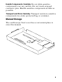
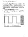
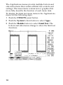
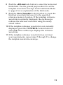
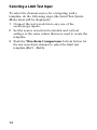
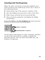
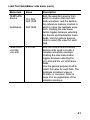
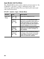
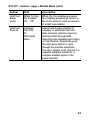
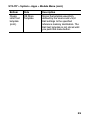
User Manual
TDS3LIM
Limit Test
Application Module
071-0934-01
*P071093401*
071093401
Copyright E Tektronix. All rights reserved. Licensed software
products are owned by Tektronix or its subsidiaries or suppliers,
and are protected by national copyright laws and international
treaty provisions.
Tektronix products are covered by U.S. and foreign patents,
issued and pending. Information in this publication supercedes
that in all previously published material. Specifications and
price change privileges reserved.
TEKTRONIX, TEK, TEKPROBE, and TekSecure are registered
trademarks of Tektronix, Inc.
DPX, WaveAlert, and e*Scope are trademarks of
Tektronix, Inc.
Contacting Tektronix
Tektronix, Inc.
14200 SW Karl Braun Drive
P.O. Box 500
Beaverton, OR 97077
USA
For product information, sales, service, and technical support:
H
H
In North America, call 1-800-833-9200.
Worldwide, visit www.tektronix.com to find contacts in
your area.
Contents
Safety Summary . . . . . . . . . . . . . . . . . . . . . . . . . . . . .
Installing the Application Module . . . . . . . . . . . . . . . .
Limit Testing Concepts . . . . . . . . . . . . . . . . . . . . . . .
TDS3LIM Overview . . . . . . . . . . . . . . . . . . . . . . . . . . .
Accessing Limit Test Menus . . . . . . . . . . . . . . . . . . . .
Creating a Limit Test Template . . . . . . . . . . . . . . . . . .
Selecting a Limit Test Input . . . . . . . . . . . . . . . . . . . .
Selecting Limit Test Responses . . . . . . . . . . . . . . . . .
Starting Limit Testing . . . . . . . . . . . . . . . . . . . . . . . . .
TDS3LIM Conventions . . . . . . . . . . . . . . . . . . . . . . . .
Menus . . . . . . . . . . . . . . . . . . . . . . . . . . . . . . . . . . . .
2
5
5
8
9
11
14
15
16
17
19
1
Safety Summary
To avoid potential hazards, use this product only as
specified. While using this product, you may need to
access other parts of the system. Read the General Safety
Summary in other system manuals for warnings and
cautions related to operating the system.
Preventing Electrostatic Damage
CAUTION. Electrostatic discharge (ESD) can
damage components in the oscilloscope and its
accessories. To prevent ESD, observe these
precautions when directed to do so.
Use a Ground Strap. Wear a grounded antistatic wrist strap
to discharge the static voltage from your body while
installing or removing sensitive components.
Use a Safe Work Area. Do not use any devices capable of
generating or holding a static charge in the work area
where you install or remove sensitive components.
Avoid handling sensitive components in areas that have a
floor or benchtop surface capable of generating a static
charge.
2
Handle Components Carefully. Do not slide sensitive
components over any surface. Do not touch exposed
connector pins. Handle sensitive components as little as
possible.
Transport and Store Carefully. Transport and store sensitive
components in a static-protected bag or container.
Manual Storage
The oscilloscope front cover has a convenient place to
store this manual.
3
4
Installing the TDS3LIM Application Module
Refer to the TDS3000, TDS3000B, and TDS3000C
Series Application Module Installation manual for
instructions on installing and testing the application
module.
Limit Testing Concepts
Limit testing is the ability to compare an active signal
with a template waveform. The following figure shows
an active waveform (dark sine wave) being compared to
a template waveform (shaded area).
5
Any part of the active waveform that exceeds the template waveform’s envelope is a limit test waveform
violation, which the oscilloscope highlights. You can set
the oscilloscope to respond to a limit test violation by
stopping limit testing, emitting a beep, and so on. The
following figure shows the highlighted (black) part of
the active waveform that exceeds the limit test envelope.
A template is an envelope waveform that consists of
minimum/maximum (min/max) pairs of sample points.
Template envelope waveforms created from 500 point
source waveforms contain 250 min/max pairs; Template
envelope waveforms created from10K point waveforms
contain 5000 min/max pairs.
6
The following figure represents how the oscilloscope
creates the template waveform limit test envelope from
user-entered vertical and horizontal division units.
Division units are referenced to graticule divisions,
where 1 major division contains 1000 millidivisions, or
mdivs. The minimum mdiv unit is 20, which equals one
screen pixel.
Vertical
limits
+
+
Horizontal
limits
=
Resulting
template
=
When a source waveform is compared with an envelope
waveform, each source waveform sample point value is
compared to the vertical and horizontal min/max values
of the corresponding envelope waveform sample point.
Any source waveform data point that is not equal to or
within the corresponding template envelope min/max
values is a violation.
7
TDS3LIM Overview
This section provides an overview of the TDS3LIM
Limit Test application module features, and describes
how to access the limit test functions.
You can do the following limit test tasks with the
TDS3LIM application module:
H Create and save up to four template waveforms in
reference memory. You can create a template
waveform from either an active input signal or from a
saved reference waveform.
H Select the channel to compare to the template. You
can compare multiple channels to a single template
waveform, compare each channel to a single template
waveform, or any combination of the above.
H Set the oscilloscope to respond to waveforms that
exceed the template limits. You can set the
oscilloscope to stop acquiring waveforms, save the
failed waveform data to a file, emit a beep, save the
screen image to the hard copy device, or any
combination of the above.
8
Accessing Limit Test Menus
You access the TDS3LIM limit test controls from either
the limit test QuickMenu or from the Applications menu.
The QuickMenu displays a single bottom and side menu
that provides quick access to all limit test functions.
To display the limit test QuickMenu, do the following
steps:
1 Push the QUICKMENU panel button.
2 Push the Menu bottom button to select Limit Test.
The oscilloscope displays the limit test bottom and
side menu items.
9
The Applications menus provide multiple bottom and
side menu items that contain all limit test controls and
settings. The menu items contain text or graphics that
more fully describe the function of each menu item.
To display the limit test menu items in the Applications
menu, do the following steps:
1 Push the UTILITY panel button.
2 Push the System bottom button to select Apps.
3 Push the Module button to select Limit Test. The
bottom and side menus change to show the limit test
functions.
10
Creating a Limit Test Template
You must create a limit test waveform template before
you can do limit testing. The TDS3LIM lets you easily
create a template by using a known good waveform
(active or reference), using the vertical and horizontal
division units to graphically define the template waveform envelope, and saving the template to reference
waveform memory (Ref1 - Ref4).
To use an active waveform to create a limit test template,
do the following steps:
1 Connect a known good waveform to any one of the
oscilloscope inputs.
2 Set the oscilloscope horizontal and vertical controls to
optimize the waveform size and position on the
screen.
NOTE. Use the Average acquisition mode to
create a smoother, cleaner template waveform.
You can also save the oscilloscope settings from
step 2 into setup memory so that later on you
can quickly reload the oscilloscope settings to
correctly display the incoming waveform for
limit testing.
NOTE. Use Envelope acquisition mode in order
to create template waveforms that include
occasional overshoots.
11
3 Push the QUICKMENU panel button.
4 Push the Menu bottom button to select Limit Test.
The oscilloscope displays the limit test bottom and
side menu items.
5 Push the Template Source/Destination side button to
select the Source field; use the general purpose knob
to select the channel to which the known good signal
is connected (Ch1 - Ch4).
You can also create a limit test waveform template
from a reference waveform by using the general
purpose knob to select a reference waveform
(Ref1-Ref4).
6 Push the Source/Destination side button to select the
Destination field; use the general purpose knob to
select the reference memory location where you want
to store the template waveform (Ref1 - Ref4).
7 Push the ±V Limit side button to select the template
vertical limits field. Use the general purpose knob to
set the template waveform envelope vertical limits.
Refer to page 6 for an explanation of the limit units.
12
8 Push the ±H Limit side button to select the horizontal
limits field. Use the general purpose knob to set the
template waveform envelope horizontal limits. Refer
to page 6 for an explanation of the limit units.
9 Push the Store Template bottom button to create the
limit test waveform and save it to the specified
reference memory location. If the template reference
waveform is currently displayed, the oscilloscope
redraws the reference waveform using the newly
stored values.
10 If the template reference waveform is not currently
displayed, push the CONTROL bottom button to
select On. The oscilloscope displays the reference
waveform.
11 If the template reference waveform does not meet
your requirements, repeat steps 7 through 9 to change
the template waveform envelope.
13
Selecting a Limit Test Input
To select the channel source for comparing with a
template, do the following steps (the Limit Test QuickMenu must still be displayed):
1 Connect the test waveform to any one of the
oscilloscope inputs.
2 Set the source waveform horizontal and vertical
settings to the same values that were used to create the
template.
3 Push the Waveform Comparisons bottom button for
the test waveform channel to select the limit test
template (Ref1 - Ref4).
14
Selecting Limit Test Responses
When the active waveform exceeds the template waveform’s envelope, the oscilloscope can do one or more of
the following actions:
H Send a hard copy of the screen to a printer or file
H Save the failing test waveform to a file on the drive
H Emit a beep each time the test waveform fails
H Stop waveform acquisition and display the failing
waveform(s)
In the QuickMenu, the On Violation side menu uses two
buttons, as shown in the following figure.
Select a response
Enable/disable a response
Use the upper menu button to select a response, and then
use the lower menu button to enable or disable the
selected response. You can select and enable any combination of responses.
15
Starting Limit Testing
After setting up a template waveform, selecting a test
waveform channel or channels, and selecting the oscilloscope limit test responses, you are ready to start limit
testing. To start limit testing, push the CONTROL
bottom menu button to select On. The oscilloscope starts
limit testing, and continues testing until a violation
occurs, at which time the oscilloscope performs the
selected response action.
NOTE. If Stop On Violation is not selected, the
oscilloscope performs all selected response tasks
(such as emit a beep) and then resumes limit
testing.
NOTE. If the oscilloscope displays an error
message stating that limit testing is turned off,
check that you have enabled the input signal
channels and that there is a valid limit test
waveform template or templates in the selected
reference memory location(s).
16
TDS3LIM Conventions
The following conventions apply to the TDS3LIM Limit
Test application module:
H You do not need to display a reference template
waveform to do limit testing.
H Moving a reference template waveform on the
display screen does not change the reference template
waveform data or the limit test parameters. Limit
testing compares active signals to the waveform
template data in reference memory.
H When limit test is set to Stop On Violation, the
oscilloscope stops signal acquisition and highlights
the waveform violations.
H While in Limit Test mode, the WAVEFORM
INTENSITY knob controls the limit test violations
display decay time. The decay time is the amount of
time that the violation highlighting remains on the
screen. The range of values is zero seconds to always
on (infinity). The Waveform Intensity knob does not
affect active signal display intensity while Limit
Testing is on.
17
H If you are using two or more waveform templates at a
time in a limit test, all the waveform templates must
use the same horizontal time base setting.
H Source waveforms you are testing must be set to the
same horizontal and vertical settings used to create
the corresponding template waveform(s).
H When limit test is set to Hard Copy On Violation or
Save To Disk, the oscilloscope completes the task
before processing any other tasks or continuing signal
acquisition.
H Save To Disk saves the waveform data using the
format specified in the SAVE/RECALL > Save
Waveform > To File menu. Please check this setting
so that you are saving waveform data in your
preferred format.
H Turning limit testing on sets the signal acquisition
mode to Sample.
18
Menus
The following sections list the limit test menus and
describe each menu function.
Limit Test QuickMenu
The Limit Test QuickMenu displays bottom and side
menus that provide fast access to all limit test functions
on one screen.
Limit Test QuickMenu: bottom menu
Menu item
Value
Description
CONTROL
OFF
ON
When on, starts limit testing.
WAVEFORM
COMPARISONS
Ch1, Ch2,
Ch3, Ch4
Ref1-Ref4,
None
Assigns a reference memory
location to a signal input channel. Repeatedly push the menu
button to cycle through the
selections. Selecting None
disables limit testing on that
channel.
(Ch3, Ch4 on
4-channel
models only)
You can compare each channel
to a separate template waveform
or compare multiple channels to
the same template.
19
Limit Test QuickMenu: side menu
Menu item
Value
Description
SETUP: On
Violation:
Printer icon
Drive icon
Speaker icon
Stop
When enabled, sets how the
oscilloscope responds to limit test
failure.
The four response actions to a limit
test failure are: send a screen
capture to the hard copy device,
save the failing waveform data to a
file on the drive, emit a beep for
each failure, and stop waveform
acquisition.
This menu uses two side menu
buttons. The upper button selects
a response in the side menu, and
the lower button enables or disables the current selection (see
page 15). You can select and
enable any combination of responses.
20
Limit Test QuickMenu: side menu (cont.)
Menu item
TEMPLATE:
Source
Value
Ch1-Ch4,
Ref1-Ref4
Destination
Ref1-Ref4
TEMPLATE:
±V Limit
±H Limit
0 to 5 div
Description
Sets the waveform source from
which to create a limit test template waveform, and the destination reference memory location in
which to store the template waveform. Pushing the side menu
button toggles between selecting
the Source and Destination menu
fields. Use the general purpose
knob to select the value for each
field.
Sets the vertical and horizontal
division units used to create a
template waveform envelope.
Pushing the side menu button
toggles between selecting the
±V Limit and the ±H Limit menu
fields.
Use the general purpose knob to
select the value for each field. The
minimum increment value is
20 mdiv, or one pixel. Refer to
page 6 for an explanation of the
template envelope.
21
Apps Module Limit Test Menu
The TDS3LIM module adds a limit test menu item to the
UTILITY > System > Apps > Module menu. The
following table describes the new limit test bottom and
side menu functions.
UTILITY > System > Apps > Module Menu
Bottom
Side
Description
Limit Test
Setupp
Limit Test
On Off
Turns limit testing on or off.
Stop On
Violation
On Off
When On, the oscilloscope stops
waveform acquisition when there is
a limit test failure on any channel.
The input waveforms and violations
remain displayed on the screen.
Beep On
Violation
On Off
When On, the oscilloscope beeps
when there is a limit test failure on
any channel.
Hard Copy On
Violation
On Off
When On, the oscilloscope sends
an image of the screen to the hard
copy device or file for each occurrence of a limit test violation.
22
UTILITY > System > Apps > Module Menu (cont.)
Bottom
Side
Description
Limit Test
Setup
(cont.)
Wfms To Disk
On Violation
On Off
When On, the oscilloscope saves
the violating waveform(s) data to a
file on the drive for each occurrence
of a limit test violation.
Limit Test
Sources
Compare
Ch1-Ch4
To
Ref1-Ref4,
None
Selects which input channel to
compare to which limit test template stored in reference memory
locations Ref1 through Ref4.
Selecting none disables limit testing
on that channel. Repeatedly push
the side menu button to cycle
through the possible selections.
You can compare each channel to a
separate template waveform, or
compare multiple inputs to the
same template.
23
UTILITY > System > Apps > Module Menu (cont.)
Bottom
Side
Description
Create
Limit Test
template
Template
Source
Selects which signal source to use
to create the limit test template.
Valid sources are channels 1
through 4 and reference waveform
memory Ref1 through Ref4.
Template
Destination
Selects which reference memory
location to use to store the limit test
template. Valid sources are Ref1
through Ref4.
±V limit
±H Limit
Sets the vertical or horizontal limits
used to create a template waveform envelope. Use the general
purpose knob to select the limit
value.
Units are in divisions,
divisions and range
from zero to five major divisions, in
increments of 20 millidivisions (1
pixel). Refer to page 6 for an
explanation of the template envelope.
24
UTILITY > System > Apps > Module Menu (cont.)
Bottom
Side
Description
Create
Limit Test
template
(cont.)
OK Store
Template
Stores the template waveform
defined by the source and ±V/H
limit settings to the specified
reference memory destination. The
limit test template is not stored until
you push this menu button.
25