1
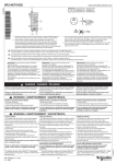
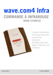
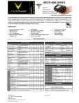
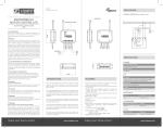
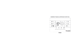
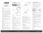
WAVE.COM4 SOUND&LIGHT OPERATING INSTRUCTIONS Consisting of: coloured lamp and operating element sound&light TECHNISCHE DOKUMENTATION OPERATING INSTRUCTIONS 3/24 LED-Coloured lamp sound&light Description LED- Coloured lamp sound&light Order reference AB0210000001 (wave.com4 sound&light coloured lamp set) AB0211000101 (sound&light operating element) for company Author Florian Aichstill Version V01 drafted 29.06.2009 CONTENTS 1.0.0 GENERAL 5 1.1.0 5 INTRODUCTION 2.0.0 MANUFACTURER’S DECLARATION 6 3.0.0 FITTING INSTRUCTIONS 7 3.1.0 3.2.0 3.3.0 3.4.0 7 7 8 9 DIMENSIONS / FITTING OPERATING ELEMENT + USB DOCK FITTING THE CONTROL ELEMENT FITTING THE COLOURED LAMP CONNECTION DIAGRAM 4.0.0 OPERATING INSTRUCTIONS FOR THE END USER 10 4.1.0 4.2.0 4.2.1. 4.2.2. 4.2.3. 4.2.4. 4.3.0 4.3.1. 4.3.2 4.3.3 4.3.2. 4.3.3. 10 11 11 11 11 12 13 13 14 14 15 16 GENERAL SAFETY NOTICES OPERATION FUNCTION DESCRIPTION OPERATING ELEMENTS TABLE OF COLOURS MODES PROGRAMMING FUNCTIONS PROGRAMMING CYCLE TIME PROGRAMMING COLOUR TRANSITION PERIOD PROGRAMMING COLOURS MASTER / SLAVE PROGRAMMING REMOTE START ACTIVATE/ DEACTIVATE 5.0.0 CONNECTION OF SEVERAL sound&light COLOURED LAMPS 16 6.0.0 CONNECTION TO THE wave.com4 SAUNA CONTROL 18 7.0.0 FAULTS, CAUSES, SOLUTIONS 19 8.0.0 TECHNICAL DATA 20 8.1.0 8.2.0 8.3.0 20 20 20 OPERATING ELEMENT LED POWER ELEMENT LED COLOURED LAMP OPERATING INSTRUCTIONS 4/24 CONTROLLED BY ABATEC Electronic AG Oberregauer Straße 48 4844 Regau, Austria Tel.: +43 (0) 7672-27720-0 Fax: +43 (0) 7672-27720-401 E-Mail: [email protected] www.abatec-ag.com OPERATING INSTRUCTIONS 5/24 1.0.0 GENERAL 1.1.0 INTRODUCTION Welcome to the user manual for the innovative, high-tech coloured lamp sound&light. This user manual is designed to help you start up the LED coloured lamp and connect it to the appropriate parts of the sauna control ”wave.com4“. You can operate the coloured lamp in 2 connection modes. a) Single – operating element master - mode Pure colour led control, no sauna function, can only be operated with one operating element. Hardware (connected to the bus bar): one colour operating element and one or more LED power elements + associated LED coloured lamp b) Sauna – operating element slave - mode The colour-led control is integrated into the sauna control and the operating element acts as a slave here. Hardware (connected to the bus bar): Colour operating element the sauna base section one or more LED power elements + associated LED coloured lamp OPERATING INSTRUCTIONS 6/24 2.0.0 MANUFACTURER’S DECLARATION We ABATEC Electronic AG Oberregauer Straße 48 A-4844 Regau ® hereby declare in relation to the product below wave.com4 sound&light Coloured lamp set AB0210000001 consisting of: Coloured lamp AB0210000101 Colour operating element AB0211000101 Control element AB0212000101 that it complies with the following directives Low-Voltage Directive 2006/95/EC EMC Directive 2004/108/EC applied harmonised standards: 1 2 3 Standard designation EN 60335-1: A12:06 EN 60335-2-53: 03+A1:2007 EN 50366:06 ABATEC Electronic AG Dipl.Ing. Friedrich Niederndorfer, MBA We reserve the right to make technical changes in the interests of progress. This description has been drafted to the best of our knowledge. Please inform your dealer or us if you find any errors therein. Many thanks! ABATEC Electronic AG for: Please note: The distribution of the colour lamp for the operation in steam showers is exclusively carried out by the company Artweger! OPERATING INSTRUCTIONS 7/24 3.0.0 FITTING INSTRUCTIONS 3.1.0 DIMENSIONS / FITTING OPERATING ELEMENT + USB DOCK Operating element: L x W x D = 120 x 92 x 50 mm; ~200 g without cable and loose; differences possible depending on customer finishes. USB DOCK: L x W x D= 30 x 92 x 9.5 mm Recess size: 40 x 25 mm Fitting suggestion: To fit the operating element, a normal hole cutter Ø 70 mm is required. Insert the colour operating element into the fitting hole and fasten to the sauna wall using the 4 screws supplied. The operating element can be fitted either outside or inside the sauna cabin. 3.2.0 FITTING THE CONTROL ELEMENT Wave.com4 Basismodul The power element is fitted preferably on the part of the cabin roof where the cables come together. (see Image. 1) Open the housing. The cover can be removed. The electrical connection must comply with standards. The connection diagram is described in Chapter 3.4.0. Figure 1 OPERATING INSTRUCTIONS 8/24 3.3.0 FITTING THE COLOURED LAMP Dimensions L x W x D = 780 x 185 x 75 mm light-emitting surface = 620 x 150 mm Recess size 765 x 158 x 75 mm ~2000 g without cable and loose Removing the transportation lock Remove transportation lock from the coloured lamp before using: Completely unscrew the two set screws on the back side of the housing counter clockwise with the enclosed socket wrench. Next insert the two enclosed plastic covers into the vent. Remove the transportation lock note from the coloured lamp. Fitting suggestion Fitting on sauna ceiling not right above the oven (Max. 130°C on the front pain) 4 mounting holes are pre-drilled on the front of the coloured lamp You should also ensure that the coloured lamp is sealed on the sauna ceiling Fitting recess 765 x 158 mm; do not enlarge recess, to ensure fitting is water-tight (!). Rear free for cooling (max. 30°C ambient temperatur e, NB: 80°C housing temperature is possible) However, depending on the sauna design or the weight of the coloured lamp (approx. 3kg) further fastening measures (e.g. screws from the front, etc.) may be required OPERATING INSTRUCTIONS 3.4.0 CONNECTION DIAGRAM 9/24 OPERATING INSTRUCTIONS 10/24 4.0.0 OPERATING INSTRUCTIONS FOR THE END USER 4.1.0 GENERAL SAFETY NOTICES Please be aware that the components in the housing of the coloured lamp are operated with dangerous mains voltage Do not connect or disconnect any live components! Always isolate the mains connection beforehand using the appropriate circuit breaker in the building’s distribution system. Electrical switch-off must be completed in all poles in line with the relevant regulations of the local Electricity Boards. Electrical work should only be carried out by a qualified expert. Any interventions by unauthorised persons shall render the warranty null and void. There is also a risk of serious electric shocks of live parts are touched. Keep the controls away from heat sources. Before start-up, check that all connections are properly connected and that no cables or parts are damaged OPERATING INSTRUCTIONS 11/24 4.2.0 OPERATION 4.2.1. FUNCTION DESCRIPTION The following description gives an overview of the programme functions and operating elements of the coloured lamp wave.com4 sound&light. 4.2.2. OPERATING ELEMENTS SWITCH ONE-/OFF By pressing the off. key, the coloured lamp and the sound function are switched on or The colour control changes into the last activated mode (automatic or manual) and the normal internal lighting goes out. (only in the sauna – operating element slave – mode) MODE-KEY By pressing the selected. key, the individual operating modes of the coloured lamp can be +/- KEY By pressing the key, parameters like colour, brightness and volume can be changed. 4.2.3. TABLE OF COLOURS Each colour number is allocated a chroma. (Standard on delivery). Colour number 1 2 3 4 5 6 7 Chroma Brightness Red Green Blue Red Yellow Green Turquoise Blue Purple White 20 20 20 20 20 20 20 20 20 0 0 0 18 17 0 20 20 20 0 0 20 0 0 0 18 20 20 20 OPERATING INSTRUCTIONS 4.2.4. 12/24 MODES Mode Light Display Symbols Description Off The coloured lamp is in the standby mode. Automatic colour The chroma is automatically further switched after the programmed time. The chroma can be manually further switched. When colour 7 ends, the control again changes to colour 1 (=rollover). If the mode is activated, this is shown with “A” on the display. Brightness The brightness of the particular chroma can be set in this mode. The adjusted brightness will be adopted for all 7 colours (0-20). The chroma never changes. No time lapse. The display shows die number belonging to the active chroma. The +/- keys can be used to select the colour desired. Manual Mode Sound Switch on-/off Play Display symbols Description Select sound function with Mode key and by pressing the ON/OFF key, de/activate the MP3 function. When the MP3 function is switched on again, it starts with the last settings MP3 is finished, using the +/- T the previous or the next track can be selected. Shuffle The shuffle mode is activated or deactivated again by simultaneously pressing the +/- key. The display shows ”Shu“. The MP3 files on the USB stick are played in random order. AUX If no USB stick is connected to the USB dock and the sound function is selected, the AUX mode is activated. The music from an external source is played. (Ipod, MP3-player, radio, etc.) OPERATING INSTRUCTIONS 13/24 Volume With Mode key to volume menu. Volume can be set in stages with +/keys (0- 20). 4.3.0 PROGRAMMING FUNCTIONS The following points provide information on the programmability of the LED coloured lamp. These settings are stored in a power failure-proof manner 4.3.1. PROGRAMMING CYCLE TIME The coloured lamp automatically changes, with the exception of ”Manual“ mode, the chroma when the Cycle time ends. This Cycle time is 5 minutes when delivered. It can be adjusted in minute steps. Proceed as follows: 1. On the operating element with the mode. 2. Press the MODE key, go to ”Automatic-colour“ key simultaneously for approx. 3 sec. 3. The programmed cycle time in minutes and the 4. Use the symbol flashes in the display. key to change the cycle time. 5. By pressing the key twice, confirm the input and thus leave the programming. OPERATING INSTRUCTIONS 4.3.2 14/24 PROGRAMMING COLOUR TRANSITION PERIOD This is the time the LED control takes on change of colour (manual or at the end of the interval period), for the colour drift from the current to the next colour. 1. On the control element with the MODE 2. Press key, go into “Automatic colour“ mode. simultaneously for approx. 3 sec (NB: do not change the colour number in the process!) 3. Pressing the key twice takes you into the setting menu. 4. The current colour transition time in seconds and the symbols and flash. 5. With the keys, the colour transition period is extended or shortened. Each change of colour the occurs with this programmed time. 6. By pressing the key once, confirm the input and thus leave the programming. 4.3.3 PROGRAMMING COLOURS The coloured lamp mixes the desired chroma from the 3 LED-base colours (Red-Green-Blue). This mix can be programmed. This gives the customer the option of programming his personal colours behind the colour numbers. Range of the individual components of the colour is always 0 to 20 (5%steps) 1. On the operating element with the MODE 2. Press key, go into ”Manual“ mode. together and simultaneously for approx. 3 sec (NB: do not change the colour number in the process!) 3. The programmed RED – portion of the chroma flashes in the display. 4. Changeable with and with the MODE key confirm the input OPERATING INSTRUCTIONS 15/24 5. The programmed GREEN – portion of the chroma flashes in the display. 6. Changeable with and with the MODE key confirm the input 7. The programmed BLUE – portion of the chroma flashes in the display 8. Changeable with and with the MODE key confirm the input On completion of all inputs, the control is again in ”Manual“ mode 4.3.2. MASTER / SLAVE PROGRAMMING Here you can set to decide whether the operating element is used in the Single/Master operation Selection „SIN“, (=standard setting,) without Wave.com4 sauna base section as master Setting for pure colourLEDcontrol without sauna function or in Slave operation Selection „SAU“, with sauna base section as Master Setting for use with Wave.com4 Sauna control 1. Disconnect 4-pin bus/supply cable from the operating element 2. Simultaneous pressing of the keys 3. Plug in cable again when pressing the key. 4. The display flashes and the mode set for the operating element appears (SIN or SAU) 5. Set the mode with the keys. 6. Confirm input with the key and jump to the ”Remote start activation“ (see 4.3.5. REMOTE START activate/ deactivate) OPERATING INSTRUCTIONS 4.3.3. 16/24 REMOTE START ACTIVATE/ DEACTIVATE In the remote start mode, the coloured lamp switches after connection of the mains voltage to the last den activated operating mode. (no standby operation) The remote start function is activated as follows: 1. After setting and confirming the mode (SIN/SAU) by pressing the key, the remote start setting flashes (Po0 or Po1) 2. Set the operating mode with the keys. Po0…….no remote start mode Po1…….remote start mode active 3. Confirm inputs with to save the changes 5.0.0 CONNECTION OF SEVERAL sound&light COLOURED LAMPS Up to 4 sound&light coloured lamps can be controlled via an operating element. To allow this, the power elements are connected to each other via a BUS line (RJ12 or RJ11 cable) and controlled via the LED coloured light operating element. The LED coloured lamps connected to an operating element can not be individually controlled but only together. There must be a power element defined to which the operating element is connected and from which the music data (MP3 or AUX) are given. This is done via a jumper located on the power element board: Jumper closed (delivery status) Power element MASTER Jumper open Power element SLAVE OPERATING INSTRUCTIONS Connection diagram: 17/24 OPERATING INSTRUCTIONS 6.0.0 CONNECTION TO THE wave.com4 SAUNA CONTROL Connection diagram: 18/24 OPERATING INSTRUCTIONS 19/24 7.0.0 FAULTS, CAUSES, SOLUTIONS This list shows possible problems, their causes and recommended procedure for resolving them. Fault Possible cause The display of the colour module cannot be activated Check power supply to the power element. If this is in order but none of the symbols on the display lights, then check the data connection of the colour operating element; Colour lamp does not light although the colour operating element shows colour numbers No lamp supply between LED coloured lamp and LED power element; Check cables/terminals; and if need be check the programming (brightness of the individual colours) The colour of the lamp and the numbers on the display change but do not correspond Check connection sequence of the connection between LED coloured lamp and LED power element One colour and its mixed colours are missing Check terminal wire of the connection between LED coloured lamp und LED power element and if need be check the programming (brightness of the individual colours) The colour of the lamp and the numbers on the display do not change Set to “Automatic“ mode; If need be connect through manually and if need be check the programming (interval period of the individual colours) The colour of the lamp and the numbers on the display change automatically Set to “Manual“ mode; If need be check programming (interval period of the individual colours) OPERATING INSTRUCTIONS 20/24 8.0.0 TECHNICAL DATA 8.1.0 OPERATING ELEMENT Connection: Power consumption: Ambient conditions: Housing: Mounting: Dimensions USB-dock: 4-pin with supply and communication lines (3m) 5V= / <100 mA normal operation (<0.5 W) 0°C – 130°C, max. 99 % rel. hum idity, noncondensing! Flush-mounted box; board; optical fibre for display; wooden front with temperature-resistant foil. Board over M2.5 bolt on wooden front; rear with flushmounted box Fasten to the sauna wall with the screws supplied L x W x D= 30 x 92 x 9.5 mm 8.2.0 LED POWER ELEMENT Supply: Power consumption: Ambient conditions: Housing: Mounting: 3-pin 230V +/-6%; 50Hz; with protective conductor (PE) Depending on chroma and brightness max. 50W. 0-50°C, max. 95% rel. h. non-co ndensing Plastic housing with cover L x B x H = 243 x 214.5 x 70 mm Fasten housing with screws to the sauna cabin 8.3.0 LED COLOURED LAMP Connection: Power consumption: Ambient conditions: Housing: Mounting: At least 5x0.75mm² +;4x0.5 mm² for Audio with 5m silicone cable Depending on chroma and brightness max. 50W Glass surface: max. 130°C outside Rear: max. 30°C ambient temperature L x W x D = 780 x 185 x 75 mm Light-emitting surface = 620 x 150 mm Size of recess 765 x 158 x 75 mm With full timber cabins additional frame into the ceiling element and make the recess larger accordingly. As per sauna design or with 4 wood screws onto the sauna ceiling NOTES: ……………………………………………………………………………………………………………… ……………………………………………………………………………………………………………… ……………………………………………………………………………………………………………… ……………………………………………………………………………………………………………… ……………………………………………………………………………………………………………… ……………………………………………………………………………………………………………… ……………………………………………………………………………………………………………… ……………………………………………………………………………………………………………… ……………………………………………………………………………………………………………… ……………………………………………………………………………………………………………… ……………………………………………………………………………………………………………… ……………………………………………………………………………………………………………… ……………………………………………………………………………………………………………… ……………………………………………………………………………………………………………… ……………………………………………………………………………………………………………… ……………………………………………………………………………………………………………… ……………………………………………………………………………………………………………… ……………………………………………………………………………………………………………… ……………………………………………………………….……………………………………………… ……………………………………………………………………………………………………………… ……………………………………………………………………………………………………………… ……………………………………………………………………………………………………………… ……………………………………………………………………………………………………………… ……………………………………………………………………………………………………………… ……………………………………………………………………………………………………………… ……………………………………………………………………………………………………………… ……………………………………………………………………………………………………………… ……………………………………………………………………………………………………………… ……………………………………………………………………………………………………………… ……………………………………………………………………………………………………………… ……………………………………………………………………………………………………………… ……………………………………………………………………………………………………………… ……………………………………………………………………………………………………………… ……………………………………………………………………………………………………………… ……………………………………………………………………………………………………………… ……………………………………………………………………………………………………………… ……………………………………………………………………………………………………………… ……………………………………………………………………………………………………………… ……………………………………………………………………………………………………………… ……………………………………………………………………………………………………………… ……………………………………………………………………………………………………………… ……………………………………………………………………………………………………………… ……………………………………………………………………………………………………………… ……………………………………………………………………………………………………………… ……………………………………………………………………………………………………………… ……………………………………………………………………………………………………………… ……………………………………………………………………………………………………………… ……………………………………………………………………………………………………………… ………………………………………………………………………………………………………………. ……………………………………………………………………………………………………………… ……………………………………………………………………………………………………………… ……………………………………………………………………………………………………………… ……………………………………………………………………………………………………………… ……………………………………………………………………………………………………………… ……………………………………………………………………………………………………………… ……………………………………………………………………………………………………………… ……………………………………………………………………………………………………………… ……………………………………………………………………………………………………………… ……………………………………………………………………………………………………………… ……………………………………………………………………………………………………………… ……………………………………………………………………………………………………………… ……………………………………………………………………………………………………………… ……………………………………………………………………………………………………………… ……………………………………………………………………………………………………………… ……………………………………………………………………………………………………………… ……………………………………………………………………………………………………………… ……………………………………………………………………………………………………………… ……………………………………………………………………………………………………………… ……………………………………………………………………………………………………………… ……………………………………………………………………………………………………………… ……………………………………………………………………………………………………………… ……………………………………………………………………………………………………………… ……………………………………………………………………………………………………………… ……………………………………………………………………………………………………………… ……………………………………………………………………………………………………………… …………………………………………………………………………………………………………….... ABATEC Electronic AG Oberregauer Straße 48 4844 Regau, Austria T +43 (0) 7672/27720-0 E [email protected] www.abatec-ag.com F +43 (0) 7672/27720-401