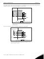
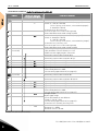
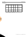
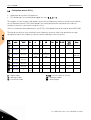
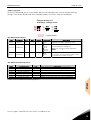
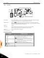
1
user's manual nx frequency converters basic i/o boards expander i/o boards adapter boards 2 • vacon index INDEX 1. General information................................................................................................................ 4 1.1 Board slots on the control board of Vacon NXS and NXP ................................................... 4 1.2 Board Slots on the control board of Vacon NXL ................................................................. 5 1.3 Option board types ............................................................................................................. 5 1.4 Technical data .................................................................................................................... 7 1.4.1 1.4.2 1.4.3 1.4.4 1.4.5 Isolation ....................................................................................................................................... 7 Analogue inputs (mA/V) .............................................................................................................. 7 Analogue outputs (mA/V) ............................................................................................................ 8 Control voltage (+24V/EXT +24V) ................................................................................................ 8 Digital input signal conversion ................................................................................................... 8 1.5 Hardware protections ...................................................................................................... 11 1.5.1 Terminal block coding............................................................................................................... 11 1.5.2 Board slot guides and allowed slots ........................................................................................ 11 1.6 Type identification number............................................................................................... 11 1.7 Defining functions to inputs and outputs.......................................................................... 11 1.8 Defining a terminal for a certain function with NCDrive programming tool..................... 13 1.9 Option board related parameters ..................................................................................... 14 2. Installation of Vacon Option Boards .................................................................................... 15 2.1 Control cables .................................................................................................................. 16 2.1.1 Cable grounding ........................................................................................................................ 17 2.2 Board information sticker ................................................................................................ 17 3. Descriptions of Vacon option boards................................................................................... 18 3.1 Basic boards OPT-A_ ....................................................................................................... 18 3.1.1 3.1.2 3.1.3 3.1.4 3.1.5 3.1.6 3.1.7 3.1.8 3.1.9 OPT-A1....................................................................................................................................... 19 OPT-A2....................................................................................................................................... 23 OPT-A3....................................................................................................................................... 24 OPT-A4....................................................................................................................................... 25 OPT-A5....................................................................................................................................... 28 OPT-A7....................................................................................................................................... 32 OPT-A8....................................................................................................................................... 37 OPT-A9....................................................................................................................................... 41 OPT-AE ...................................................................................................................................... 42 3.2 I/O Expander Boards OPT-B_ ........................................................................................... 46 3.2.1 3.2.2 3.2.3 3.2.4 3.2.5 OPT-B1 ...................................................................................................................................... 47 OPT-B2 ...................................................................................................................................... 49 OPT-B4 ...................................................................................................................................... 50 OPT-B5 ...................................................................................................................................... 51 OPT-B8 ...................................................................................................................................... 52 Tel.+358 (0)201 2121 • Fax +358 (0)201 212 205 index vacon • 3 3.2.6 OPT-B9 ...................................................................................................................................... 54 3.2.7 OPT-BB ...................................................................................................................................... 55 3.3 Adapter Boards OPT-D_ ................................................................................................... 59 3.3.1 OPT-D1 ...................................................................................................................................... 60 3.3.2 OPT-D2 ...................................................................................................................................... 62 3.3.3 OPT-D3 ...................................................................................................................................... 65 3.3.4 OPT-D6 ...................................................................................................................................... 67 4. Vacon Option Boards – operational details ........................................................................... 68 24-hour support +358 (0)40 8371 150 • Email: [email protected] 4 • vacon general information GENERAL INFORMATION 1. Vacon NX range embodies a wide selection of expander and adapter boards with which the available I/O of Vacon NX frequency converter can be increased and its versatility improved. The input and output configuration (I/O) of Vacon NX is designed with modularity in mind. The total I/O is comprised of option boards, each having its own input and output configuration. The boards contain not only normal analogue and digital inputs and outputs, but also fieldbuses and additional application-specific hardware. The basic, expander and adapter boards are placed in the board slots on the control board of the frequency converter. The I/O boards are usually interchangeable between different Vacon types, i.e. NXS and NXP. However, the control boards of these types differ from each other to some extent which means that the use of some I/O boards in different Vacon frequency converter types may be restricted. 1.1 Board slots on the control board of Vacon NXS and NXP A B C D E Figure 1-1. Board slots on control board of the Vacon NXS and NXP The control board is situated inside the control unit of the Vacon NX frequency converter. There are five board slots (labelled A to E) on the control board of NXS and NXP (See User’s Manual, Chapter 6.2.1): The connectability of different option boards to different slots depends greatly on the type of the board. For more information on this, see Chapter 1.2. See also the descriptions of the options boards on pages 18 to 68. Usually, when the frequency converter is delivered from the factory, the control unit includes at least the standard compilation of two basic boards (I/O board and relay board) which are normally installed in slots A and B. The I/O boards mounted at the factory are indicated in the type code of the frequency Tel.+358 (0)201 2121 • Fax +358 (0)201 212 205 1 general information vacon • 5 converter. The three expander slots C, D and E are available for different option boards i.e. I/O expander boards, fieldbus boards and adapter boards. 1.2 Board Slots on the control board of Vacon NXL Option Board Figure 1-2. Board slots on control board of Vacon NXL. The control board of NXL includes fixed standard I/O and one place for option boards (see User’s Manual of NXL, Chapter 6.2.). The most typical option board for NXL, OPT-AA, is specified in the User’s Manual, Chapter 10. 1.3 Option board types The Vacon option boards are divided in four groups according to their characteristics: types A, B, C and D. Short descriptions of the types below: OPT-A_ • • Basic boards used for basic I/O (NXS, NXP); normally pre-installed at the factory This board type uses slots A, B or C. See pages 18 to 45 for a detailed presentation of the boards of this type. See also the principle diagram on the options boards and their equipment on page 68. OPT-B_ • • Option boards used for I/O expansion Normally pluggable into slots B, C, D and E See pages 46 to 58 for a detailed presentation of the boards of this type. See also the principle diagram on the options boards and their equipment on page 68. 24-hour support +358 (0)40 8371 150 • Email: [email protected] 1 6 • vacon general information OPT-C_ • • Fieldbus boards (e.g. Profibus or Modbus) These boards are connected to slots D and E. See a separate manual on each individual Fieldbus Board. Ask factory or your nearest distributor for more information. OPT-D_ • • • Adapter boards Boards with fiber optic adapters, e.g. System Bus Fiber Optic Adapter Board. Connect the adapter boards to slots D and E (see however page 65). See pages 59 to 68 for a detailed presentation of the boards of this type. See also the principle diagram on the options boards and their equipment on page 69. Tel.+358 (0)201 2121 • Fax +358 (0)201 212 205 1 general information 1.4 vacon • 7 Technical data The data in the table below applies to the inputs and outputs on all basic and expander boards. Safety (all boards) Input/output type Analogue inputs (AI), voltage Analogue inputs (AI), current Digital inputs (DI), DC voltage controlled Digital inputs (DI), AC voltage controlled Auxiliary voltage (output) (+24V) Auxiliary voltage (input) (ext. +24V) Reference voltage (output) (+10Vref) Analogue output (AO), current (mA) Analogue output (AO), voltage (V) Relay outputs (RO) Thermistor input (TI) Encoder control voltage (+5V/+12V/ +15V/+24V) Encoder connections (inputs, outputs) Environment (all boards) Ambient operating temperature Storing temperature Humidity Altitude Vibration Comply with EN50178, C-UL and EN60204-1 Inputs/outputs galvanically isolated; Isolation voltage rate 500V Specification 0…±10V, Ri ≥ 200 kΩ, single-ended; Resolution 10 bits/0.1%, accuracy ±1% of the full display (–10…+10V joystick control) 0(4)…20mA, Ri = 250Ω, differential Resolution 10 bits/0.1%, accuracy ±1% of the full display 24V: "0"≤10V, "1"≥18V, Ri > 5kΩ Control voltage 42…240 VAC "0"<33V, "1">35V 24V (±15%), max 250mA (total summarized load from ext. +24V outputs, max. 150 mA from one board. 24VDC (±10%, max. ripple voltage 100mV RMS), max. 1A. In special applications where PLC type functions are included in the control unit the input can be used as external auxiliary power supply for control boards as well as I/O boards. 10V – 0% – +2%, max. 10mA 0(4)…20mA, RL<500Ω, resolution 10 bits/0.1%, accuracy ≤ ±2% 0(2)…10V, RL ≥ 1kΩ, resolution 10 bits, accuracy ≤ ±2% Switching capacity 24VDC/8A 250VAC/8A 125VDC/0.4A Max. continuous load 2A rms Min.switching load: 5V/10mA Rtrip = 4.7kΩ (PTC type) See OPT-A4, OPT-A5, OPT-A7, OPT-AE and OPT-BB technical data See OPT-A4, OPT-A5, OPT-A7, OPT-AE and OPT-BB technical data –10…55°C –40…60°C <95%, no condensation allowed Ma 1000m 0,5 G at 9…200 Hz Table 1-1. Technical data 1.4.1 Isolation The control connections are isolated from the mains potential and the I/O ground is connected directly to the frame of the frequency converter. Digital inputs and relay outputs are isolated from the I/O ground. For digital input arrangements, see Chapter Digital input signal conversions on page 8. 1.4.2 Analogue inputs (mA/V) Analogue inputs of I/O boards can be used as either current inputs or voltage inputs (see detailed description of each board). The signal type is selected with a jumper block on the board. In case the voltage type input is used you still have to define the voltage range with another jumper block. The factory default value for the analogue signal type is given in the description of the board. For detailed information, see the description of the board in question. 24-hour support +358 (0)40 8371 150 • Email: [email protected] 1 8 • vacon 1.4.3 general information Analogue outputs (mA/V) In the same way as in the analogue inputs, the output signal type (current/voltage) can be selected with jumper except for some expander boards with analogue outputs used only with current signals. 1.4.4 Control voltage (+24V/EXT +24V) The control voltage output +24V/EXT+24V can be used in two ways. Typically, the +24V control voltage is wired to digital inputs through an external switch. The control voltage can also be used to power-up external equipment, such as encoders and auxiliary relays. Observe that the specified total load on all available +24V/EXT+24V output terminals may not exceed 250mA. The maximum load on the +24V/EXT+24V output per board is 150mA. See Figure 1-3. max. max. max. max. max. 150mA 150mA 150mA 150mA 150mA +24V out + +24V + +24V + +24V + +24V = max. 250mA out out out out Figure 1-3. Maximum loads on +24V/EXT+24V output The +24V/EXT+24V outputs can further be used to externally power-up the control board as well as the basic and expander boards. If an external power supply is connected to EXT+24V output, the control board, basic boards and expander boards remain live even if mains should be lost on the frequency converter. This ensures sufficient functioning of the control logic (not the motor control, however) and some alarms in exceptional power-loss situations. Furthermore, fieldbus links remain powered which enables e.g. the Profibus Master to read valuable data on the frequency converter. Note: The power unit is not powered through the EXT+24V and therefore the motor control does not work if the mains is lost. Requirements for an external power back-up: output voltage +24DC±10%, max. ripple voltage 100mV RMS max. current 1A 1A external fuse (no internal short-circuit protection on the control board Note: Analogue outputs and inputs do not work with only +24V supplied to the control unit. If there is a +24V/EXT+24V output on the board it is short-circuit protected locally. Should one of the +24V/EXT+24V outputs short-circuit, the others would remain powered because of the local protection. 1.4.5 Digital input signal conversion The active signal level depends on which potential the common input CMA (and CMB if available) is connected to. The alternatives are +24V or Ground (0V). See Figure 1-4, Figure 1-5 and Figure 1-6. The 24-volt control voltage and the ground for the digital inputs and the common input (CMA) can be either internal or external. Tel.+358 (0)201 2121 • Fax +358 (0)201 212 205 1 general information vacon • 9 Some typical input signal conversion examples are shown below. If you use the internal +24V from the frequency converter, the following arrangements are possible: +24V/EXT+24V DI1 DI2 DI3 GND Jumper setting: = CMA connected to GND Figure 1-4. If CMA is connected to GND with inboard jumper the internal +24V is used and the CMA terminal ed not be wired If you use an external +24V the following arrangements are possible: External +24V +24V/EXT+24V DI1 DI2 DI3 GND Ground Jumper setting: = CMA isolated from GND Figure 1-5. Positive logic with external +24V when CMA is isolated from GND using onboard jumper. The input is active when the switch is closed. 24-hour support +358 (0)40 8371 150 • Email: [email protected] 1 10 • vacon general information Ground +24V/EXT+24V DI1 DI2 DI3 GND External +24V Jumper setting: = CMA isolated from GND Figure 1-6. Negative logic with external +24V when CMA is isolated with onboard jumper. The input is active when the switch is closed (0V is the active signal). You can make the positive and negative logic arrangements also with the internal +24V. Place the jumper block in the 'CMA isolated from GND' position (as above) and wire the CMA terminal to the GND terminal of the frequency converter. Tel.+358 (0)201 2121 • Fax +358 (0)201 212 205 1 general information 1.5 vacon • 11 Hardware protections 1.5.1 Terminal block coding In order to avoid incorrect connections of terminal blocks to boards, some terminal blocks as well as related terminal connectors on the board are uniquely coded. For more information, see the description of the individual board. 1.5.2 Board slot guides and allowed slots You cannot mount an option board into any slot. Table 4-1 and Table 4-2 show which slots are allowed for which option boards. For reasons of safety, slots A and B are protected in hardware against mounting of unallowed boards. As regards mounting of unallowed boards into slots C, D and E, the boards just will not work, there is no danger of health or equipment damage. "Slot guide" Board grooves Figure 1-7. Board guide to prevent incorrect mountings 1.6 Type identification number Note: This information is relevant only for special applications designers using the Vacon NC1131-3 engineering tool. Each Vacon OPTxx board has a unique type designation code. Besides the type designation code, each board has a unique Type identification number which is used by the system program to identify which board is plugged into which board slot. The system program and the application use the Type ID also to establish the needed connections in order to achieve the desired functionality of the available I/O boards in the control unit. The ID code is loaded in the memory of the board. 1.7 Defining functions to inputs and outputs How to connect functions and the available I/O depends on the application you use. The Vacon All in One Application Package includes seven applications: Basic Application, Standard Application, PID Control Application, Multi-Step Speed Control Application, Local/Remote Control Application, Pump and Fan Control Application with Autochange and Multipurpose Control Application (see Application 24-hour support +358 (0)40 8371 150 • Email: [email protected] 1 12 • vacon general information Manuals). All but two applications of these use the conventional Vacon method to connect functions and the I/O. In the Function to Terminal Programming Method (FTT), you have a fixed input or output that you define a certain function for. The mentioned two applications, Pump and Fan Control and Multipurpose Control Application, however, use the Terminal to Function Programming Method (TTF) in which the programming process is carried out the other way round: Functions appear as parameters which the operator defines a certain input/output for. Connecting a certain input or output to a certain function (parameter) is done by giving the parameter an appropriate value, the address code. The code is formed of the Board slot on the Vacon NX control board (see page 4 and 5) and the respective input/output number. See below. READY I/Oterm AI Ref Faul/Warn DigOUT:B.1 Function name Slot Terminal type Terminal number Example: You use the Pump and Fan Control Application. You want to connect the digital output function Reference fault/warning (parameter 2.3.1.7) to the digital output DO1 on the basic board OPT-A1. First find the parameter 2.3.1.7 on the keypad. Press the Menu button right once to enter the edit mode. On the value line, you will see the terminal type on the left (DigIN, DigOUT, An.IN, An.OUT) and on the right, the present input/output the function is connected to (B.3, A.2 etc.), or if not connected, a code 0.#. When the value is blinking, hold down the Browser button up or down to find the desired board slot and input/output number. The program will scroll the board slots starting from 0 and proceeding from A to E and the I/O numbers from 1 to 10. Once you have set the desired code, press the Enter button once to confirm the change. READY I/Oterm AI Ref Faul/Warn DigOUT:0.0 READY I/Oterm AI Ref Faul/Warn DigOUT:0.0 READY I/Oterm AI Ref Faul/Warn DigOUT:A.1 enter Tel.+358 (0)201 2121 • Fax +358 (0)201 212 205 1 general information 1.8 vacon • 13 Defining a terminal for a certain function with NCDrive programming tool If you use the NCDrive Programming Tool for parametrizing you will have to establish the connection between the function and input/output in the same way as with the control panel. Just pick the address code from the drop-down menu in the Value column (see Figure 1-8 below). Figure 1-8. Screenshot of NCDrive programming tool; Entering the address code ! WARNING Be ABSOLUTELY sure not to connect two functions to one and same output in order to avoid function overruns and to ensure flawless operation. Note: The inputs, unlike the outputs, cannot be changed in RUN state. 24-hour support +358 (0)40 8371 150 • Email: [email protected] 1 14 • vacon 1.9 general information Option board related parameters Some of the input and output functions of certain option boards are controlled with associated parameters. The parameters are used to set the signal ranges for analogue inputs and outputs as well as values for different encoder functions. The board-related parameters can be edited in the Expander Board Menu (M7) of the control keypad. Enter the following menu level (G#) with the Menu button right. At this level, you can browse through slots A to E with the Browser buttons to see what expander boards are connected. On the lowermost line of the display you also see the number of parameters associated with the board. Edit the parameter value as shown below. For more information on the keypad operation, see Vacon NX User's Manual, Chapter 7. See Figure 1-9. R EA DY R EA DY I/Oterm I/Oterm D:NXOPTC2 Monitor G1ÎG2 V1 ÎV2 READY READY READY I/Oterm I/Oterm Expander boards G1ÎG5 C:NXOPTC1 Parameters G1 ÎG2 READY I/Oterm I/Oter m P1ÎP4 READY CHANGE VALUE I/Oterm Slave address 126 Slave address 126 enter CONFIRM CHANGE REA DY I/Oterm Baud rate Auto Figure 1-9. Board parameter value editing Note: Fieldbus boards (OPT-C_) also have fieldbus-related parameters. These boards are, however, described in the separate fieldbus board manuals (please visit http://www.vacon.com/support/documents.html. Tel.+358 (0)201 2121 • Fax +358 (0)201 212 205 1 installation 2. vacon • 15 INSTALLATION OF VACON OPTION BOARDS ! NOTE It is not allowed to add or replace option boards or fieldbus boards on a frequency converter with the power switched on. This may damage the boards. A Vacon NX frequency converter B Remove the cable cover. C Open the cover of the control unit. Continues on next page 24-hour support +358 (0)40 8371 150 • Email: [email protected] 2 16 • vacon D installation Install the option board in a correct slot on the control board of the frequency converter. On attaching (also removing) the board, hold it in horizontally straight position to avoid twisting the connector pins. See the photos below. Make sure that the board (see below) fits tightly in the metal clamp and the plastic groove. If the board seems to be difficult to fit in the slot you may have to check the allowed slots for your option board. Note: Check that the jumper settings on the board correspond to you needs. Finally, close the cover of the frequency converter and the cable cover. 2.1 Control cables The control cables used shall be at least 0.5mm2 screened multicore cables. The maximum terminal wire size is 2.5mm2 for the relay terminals and 1.5 mm2 for other terminals. Find the tightening torques of the option board terminals in the table below. Tightening torque Terminal screw Nm lb-in. Relay and thermistor 0.5 4.5 terminals (screw M3) Other terminals 0.2 1.8 (screw M2.6) Table 2-1. Tightening torques of terminals Tel.+358 (0)201 2121 • Fax +358 (0)201 212 205 2 installation vacon • 17 Cable type Level H, C Level L Control cable 4 4 Table 2-2. Cable types required to meet standards. Level H = EN 61800-3+A11, 1st environment, restricted distribution EN 61000-6-4 Level L = EN61800-3, 2nd environment 4 = Screened cable equipped with compact low-impedance shield (NNCABLES /Jamak, SAB/ÖZCuY-O or similar). 2.1.1 Cable grounding We recommend to ground the control cables in the manner presented above. Strip the cable at such distance from the terminal that you can fix it to the frame with the grounding clamp. Figure 2-1. Grounding of control cable 2.2 Board information sticker Each I/O option board package delivered by the factory includes a sticker (shown below) where possible modifications made in the frequency converter are noted. Please check Option board (1), mark the board type (2), the slot into which the board is mounted (3) and the mounting date (4) on the sticker. Finally, attach the sticker on your drive. 2 1 Drive m odified: 4 Option board: N XOPT................ Date:................... in slot: A B C D E IP54 upgrade/ Collar Date:................... EMC level modified: H to T / T to H Date:................... 3 24-hour support +358 (0)40 8371 150 • Email: [email protected] 2 18 • vacon descriptions 3. DESCRIPTIONS OF VACON OPTION BOARDS 3.1 Basic boards OPT-A_ • • Basic boards used for basic I/O; normally pre-installed at the factory This board type uses slots A, B and C. The standard Vacon NXS and NXP frequency converters contain two boards placed in slots A and B. The board in slot A (OPT-A1, OPT-A8 or OPT-A9) has digital inputs, digital outputs, analogue inputs and an analogue output. The board in slot B (OPT-A2) has two change-over relay outputs. As an alternative to OPT-A2, a board of type OPT-A3 can also be placed in slot B. In addition to the two relay outputs, this board has one thermistor input. The boards you wish to have installed in your frequency converter have to be defined in the type designation code of the frequency converter when ordering it from the factory. I/O board Allowed slots DI DO AI AO NXS NXP OPT-A1 A 6 1 2 (mA/V), incl. -10…+10V 1 (mA/V) NXS NXP OPT-A2 B NXS NXP OPT-A3 B FC type 1) NXS NXP OPT-A4 C NXS1) NXP OPT-A5 C NXP OPT-A7 C RO Other +10Vref +24V/ EXT+24V 2 (NO/NC) 1 (NO/NC) + 1 NO 3 DI encoder (RS-422) + 2 DI (qualifier & fast input) 3 DI encoder (wide range) + 2 DI (qualifier & fast input) 6 (enc.) TI 1 +5V/+15V/+24V (progr.) +15V/+24V (progr.) +15V/+24V (progr.) 2 (enc) NXS NXP OPT-A8 A 6 1 NXS NXP OPT-A9 A 6 1 NXS1) NXP OPT-AE C 3 DI encoder (wide range) 2 (Enc.) 2 (mA/V), 1 (mA/V) incl. -10…+10V (decoupled (de-coupled from GND) from GND) 2 (mA/V), incl. 1 (mA/V) -10…+10V +10Vref (decoupled from GND) +24V/ EXT+24V +10ref (2,5 mm terminals) +24V/ EXT+24V +15V/+24V (progr.) Table 3-1. Vacon NX Basic boards and their equipment 1) Encoder board can be used in Vacon NXS with special applications only. DI = Digital input AI = Analogue input DO = Digital output AO = Analogue output TI = Thermistor input RO = Relay output Tel.+358 (0)201 2121 • Fax +358 (0)201 212 205 2 descriptions OPT-A1 OPT-A1 3.1.1 vacon • 19 Figure 3-1. Vacon OPT-A1 option board Description: Standard I/O board with digital inputs/outputs and analogue inputs/outputs Allowed slots: A Type ID: 16689 Terminals: Two terminal blocks (coded = mounting of blocks in wrong order prevented, terminals #1 and #12); Screw terminals (M2.6) Jumpers: 4; X1, X2, X3 and X6 (See Figure 3-2.) Board parameters: Yes (see page 22) 24-hour support +358 (0)40 8371 150 • Email: [email protected] 3 20 • vacon descriptions I/O terminals on OPT-A1 (coded terminals painted black) OPT-A1 Terminal Parameter reference on keypad and NCDrive 1 2 +10 Vref AI1+ 3 AI1– 4 AI2+ 5 AI2– 6 24 Vout (bidirectional) 7 GND 8 9 10 DIN1 DIN2 DIN3 11 CMA 12 13 24 Vout (bidirectional) GND 14 15 16 17 DIN4 DIN5 DIN6 CMB DigIN:A.4 DigIN:A.5 DigIN:A.6 18 19 AO1+ AO1– AnOUT:A.1 20 DO1 DigOUT:A.1 An.IN:A.1 An.IN:A.2 DigIN:A.1 DigIN:A.2 DigIN:A.3 Technical information Reference output +10V; Maximum current 10 mA Selection V or mA with jumper block X1 (see page 21): Default: 0– +10V (Ri = 200 kΩ) (-10V..+10V Joy-stick control, selected with ajumper) 0– 20mA (Ri = 250 Ω) Resolution 0.1%; Accuracy ±1% Differential input if not connected to ground; Allows ±20V differential mode voltage to GND Selection V or mA with jumper block X2 (see page 21): Default: 0– 20mA (Ri = 250 Ω) 0– +10V (Ri = 200 kΩ) (-10V..+10V Joy-stick control, selected with a jumper) Resolution: 0.1%; Accuracy ±1% Differential input if not connected to ground; Allows ±20V differential mode voltage to GND 24V auxiliary voltage output. Short-circuit protected. ±15%, maximum current 150 mA, see 1.4.4 +24Vdc external supply may be connected. Galvanically connected to terminal #12. Ground for reference and controls Galvanically connected to terminals #13,19. Digital input 1 (Common CMA); Ri = min. 5kΩ Digital input 2 (Common CMA); Ri = min. 5kΩ Digital input 3 (Common CMA); Ri = min. 5kΩ Digital input common A for DIN1, DIN2 and DIN3. Connection by default to GND. Selection with jumper block X3 (see page 21): Same as terminal #6 Galvanically connected to terminal #6. Same as terminal #7 Galvanically connected to terminals #7 and 19 Digital input 4 (Common CMB); Ri = min. 5kΩ Digital input 5 (Common CMB); Ri = min. 5kΩ Digital input 6 (Common CMB); Ri = min. 5kΩ Digital input common B for DIN4, DIN5 and DIN6. Connection by default to GND. Selection with jumper block X3 (see page 21): Analogue output Output signal range: Current 0(4)–20mA, RL max 500Ω or Voltage 0—10V, RL >1kΩ Selection with jumper block X6 (see page 21): Resolution: 0.1% (10 bits); Accuracy ±2% Open collector output Maximum Uin = 48VDC Maximum current = 50 mA Table 3-2. OPT-A1 I/O terminals Tel.+358 (0)201 2121 • Fax +358 (0)201 212 205 3 descriptions vacon • 21 Jumper selections Jum per block X 1 : AI1 m ode A B C A B C Jum per block X 2 : AI2 m ode D A AI1 mode: 0...20mA; Current input B C D A A B C A A Jum per block X 6 : AO 1 m ode A B C B C B C D B C D B C D AI2 mode: Voltage input; -10...10V Jum per block X 3 : CM A a nd CM B grounding D AO1 mode: 0...20mA; Current output A D AI2 mode: Voltage input; 0...10V (differential) D AI1 mode: Voltage input; -10...10V C AI2 mode: Voltage input; 0...10V D AI1 mode: Voltage input; 0...10V (differential) B AI2 mode: 0...20mA; Current input AI1 mode: Voltage input; 0...10V A OPT-A1 There are four jumper blocks on the OPT-A1 board. The factory defaults and other available jumper selections are presented below. D CMB connected to GN D CMA connected to GN D CMB isolated from GN D CMA isolated from GN D CMB and CMA internally connected together, isolated from GN D AO1 mode: Voltage output; 0...10V = Factory default Figure 3-2. Jumper block selection on OPT-A1 24-hour support +358 (0)40 8371 150 • Email: [email protected] 3 22 • vacon descriptions OPT-A1 OPT-A1 parameters Number Parameter Min Max Default 1 AI1 mode 1 5 3 2 AI2 mode 1 5 1 3 AO1 mode 1 4 1 Note 1 = 0...20mA 2 = 4...20mA 3 = 0...10V 4 = 2...10V 5 = -10...+10V 1 = 0...20mA 2 = 4...20mA 3 = 0...10V 4 = 2...10V 5 = -10...+10V 1 = 0...20mA 2 = 4...20mA 3 = 0...10V 4 = 2...10V Table 3-3. OPT-A1 board-related parameters Tel.+358 (0)201 2121 • Fax +358 (0)201 212 205 3 descriptions OPT-A2 OPT-A2 3.1.2 vacon • 23 Description: Standard Vacon NX frequency converter relay board with two relay outputs Allowed slots: B Type ID: 16690 Terminals: Two terminal blocks; Screw terminals (M3); No coding Jumpers: None Board parameters: None I/O terminals on OPT-A2 Terminal 21 22 23 24 25 26 Parameter reference on keypad and NCDrive RO1/normal closed RO1/common RO1/normal open RO2/normal closed RO2/common RO2/normal open Technical information Relay output 1 (NO/NC) Switching capacity DigOUT:B.1 Min. switching load Relay output 2 (NO/NC) Switching capacity DigOUT:B.2 Min. switching load 24VDC/8A 250VAC/8A 125VDC/0.4A 5V/10mA 24VDC/8A 250VAC/8A 125VDC/0.4A 5V/10mA Table 3-4. OPT-A2 I/O terminals 24-hour support +358 (0)40 8371 150 • Email: [email protected] 3 24 • vacon OPT-A3 OPT-A3 3.1.3 descriptions Description: Relay board with two relay outputs and one thermistor input for Vacon NX frequency converter Allowed slots: B Type ID: 16691 Terminals: Three terminal blocks; Screw terminals (M3); No coding. Jumpers: None Board parameters: None I/O terminals on OPT-A3 Terminal 21 22 23 25 26 Parameter reference on keypad and NCDrive RO1/normal closed RO1/common RO1/normal open RO2/common RO2/normal open Technical information Relay output 1 (NO/NC) Switching capacity DigOUT:B.1 Min. switching load Relay output 2 (NO) Switching capacity DigOUT:B.2 Min. switching load 28 29 TI1+ TI1– DigIN:B.1 24VDC/8A 250VAC/8A 125VDC/0.4A 5V/10mA 24VDC/8A 250VAC/8A 125VDC/0.4A 5V/10mA Thermistor input; Rtrip = 4.7 kΩ (PTC) Table 3-5. OPT-A3 I/O terminals Tel.+358 (0)201 2121 • Fax +358 (0)201 212 205 3 descriptions 3.1.4 vacon • 25 OPT-A4 Description: OPT-A4 Jumper X4 Encoder board for Vacon NXP. Encoder input board with programmable control voltage for an encoder The encoder board OPT-A4 is for TTL type encoders (TTL, TTL(R)) providing input signal levels that meet the RS_422 interface standard. Encoder inputs A, B and Z are not galvanically isolated. The OPT-A4 board includes, too, the qualifier input ENC1Q (meant to trace the Z-pulse in certain situations) and a special/fast digital input DIC4 (used to trace very short pulses). These two inputs are used in special applications. The TTL type encoders do not have an internal regulator and use therefore a supply voltage of +5V±5% whereas the TTL(R) type encoders have an internal regulator and the supply voltage can be e.g. +15V±10% (depending on the encoder manufacturer). Allowed slots: C Type ID: 16692 Terminals: One terminal block; Screw terminals (M2.6); Coding in terminal #3. Jumpers: 2; X4 and X5 (see page 26) Board parameters: Yes (see page 27) 24-hour support +358 (0)40 8371 150 • Email: [email protected] 3 26 • vacon descriptions I/O terminals on OPT-A4 (coded terminal painted black) OPT-A4 Terminal 1 2 3 DIC1A+ DIC1A– DIC2B+ 4 5 6 7 8 9 10 DIC2B– DIC3Z+ DIC3Z– ENC1Q DIC4 GND +5V/+15V/+24V Parameter reference Keypad/NCDrive Technical information Pulse input A Pulse input B; phase shift of 90 degrees compared to Pulse input A Pulse input Z; one pulse per revolution Reserved for future use Reserved for future use Ground for control and inputs ENC1Q and DIC4 Control voltage (auxiliary voltage) output to encoder; Output voltage selectable with jumper X4. See chapter 1.4.4 Table 3-6. OPT-A4 I/O terminals Technical data: Encoder control voltage, +5V/+15V/+24V Encoder input connections, inputs A+, A–, B+, B–, Z+, Z– Control voltage selectable with jumper X4. Max. input frequency ≤150kHz Inputs A, B and Z are differential Encoder inputs are RS-422 interface compatible Max. load per encoder input Ilow = Ihigh ≈ 25mA Max. input frequency ≤10kHz Min. pulse length 50µs Digital input 24V; Ri>5kΩ Digital input is single-ended; connected to GND Qualifier input ENC1Q Fast digital input DIC1 Jumper selections On the OPT-A4 board, there are two jumper blocks. The jumper X2 is used to define the status of the termination resistor (R=135Ω). The jumper X4 is used to program the control voltage (auxiliary voltage). The factory default and other available jumper selections are presented below. Jum per block X 2 : Termina tion resistor 24V 15V 5V 24V 15V 5V 24V 15V 5V Jum per block X 4 : Aux ilia ry volta ge level A B C Auxiliary voltage +5V Auxiliary voltage +15V = Factory default A B C Auxiliary voltage +24V Termination resistor used Termination resistor not used Tel.+358 (0)201 2121 • Fax +358 (0)201 212 205 3 descriptions vacon • 27 Encoder connection – Differential OPT-A4 board Twisted pairs with own shield . . 10 9 +5V** GND A+ Encoder AB+ B*If external supply is used remember to connect the ground of external supply to terminal #9 of the OPT-A4 and to the encoder ground **+5V/15V/+24V +5V/+15V/+24V GND 1 2 3 4 5 6 7 8 . . DIC1A+ DIC1ADIC2B+ DIC2BDIC3Z+ DIC3ZENC1Q DIC1 OPT-A4 5V/15V/24V from the OPT-A4board or from external supply* Figure 3-3. RS-422 type encoder connection using differential inputs Note: The encoder pulses are handled by Vacon software as presented below: OUTPUT SIGNALS Clockwise, seen from shaft 360º el. 1 period 90º el. (channel separation) A B OPT-A4 parameters Number Parameter Pulse/revolutio n Min Max Default 1 65535 1024 7.3.1.2 Invert direction 0 1 0 7.3.1.3 Reading rate 0 4 1 7.3.1.1 Note 0 = No 1 = Yes Time used to calculate speed actual value. Note: Use value 1 in Closed Loop mode. 0 = No 1 = 1 ms 2 = 5 ms 3 = 10 ms 4 = 50 ms Table 3-7. OPT-A4 board-related parameters 24-hour support +358 (0)40 8371 150 • Email: [email protected] 3 28 • vacon 3.1.5 descriptions OPT-A5 Jumper X4 Description: Encoder board for Vacon NXP. Encoder input board with programmable control voltage for an encoder. OPT-A5 The OPT-A5 board is designed for HTL (High voltage Transistor Logic) type encoders (voltage output type push-pull HTL, open collector output type HTL) which provide input signal levels dependent on the supply voltage of the encoder. The encoder inputs A, B and Z are galvanically isolated. The OPT-A5 board includes, too, the qualifier input ENC1Q (meant to trace the Z-pulse in certain situations) and a fast digital input DIC4 (used to trace very short pulses). These two inputs are used in special applications. The OPT-A5 is similar to the OPT-A4 in connections but the encoder inputs A, B and Z have different signal levels (voltage level). The input levels for A, B and Z of the OPT-A4 are compatible with RS-422 while those of the OPT-A5 are more general wide range inputs. Inputs ENC1Q and DIC4 are identical in both boards. Allowed slots: C Type ID: 16693 Terminals: One terminal block; Screw terminals (M2.6); Coding in terminal #3. Jumpers: 1; X4 (see page 30) Board parameters: Yes (see page 27) Tel.+358 (0)201 2121 • Fax +358 (0)201 212 205 3 descriptions vacon • 29 I/O terminals on OPT-A5 (coded terminal painted black) Terminal 1 2 3 DIC1A+ DIC1A– DIC2B+ 4 5 DIC2B– DIC3Z+ 6 7 8 9 10 DIC3Z– ENC1Q DIC4 GND +15V/+24V Parameter reference Keypad/NCDrive Technical information Pulse input A (differential); Voltage range 10…24V Pulse input B; phase shift of 90 degrees compared to Pulse input A (differential); Voltage range 10…24V Pulse input Z; one pulse per revolution (differential); Voltage range 10…24V Reserved for future use Reserved for future use Ground for control and inputs ENC1Q and DIC4 Control voltage (auxiliary voltage) output to encoder; Output voltage selectable with jumper X4. See chapter 1.4.4. Table 3-8. OPT-A5 I/O terminals Note: Encoder inputs are wide range inputs that can be used with encoders using +15V or +24V Technical data: Fast digital input DIC1 Control voltage selectable with jumper X4. Max. input frequency ≤150kHz Inputs A, B and Z are differential Max. input frequency ≤10kHz Min. pulse length 50µs Digital input 24V; Ri>5kΩ Digital input is single-ended; connected to GND OPT-A5 Encoder control voltage, +15V/+24V Encoder input connections, inputs A+, A–, B+, B–, Z+, Z– Qualifier input ENC1Q Note: A high pulse frequency combined with a great cable capacitance places a considerable load on the encoder. Apply therefore as low a voltage as possible for the encoder supply, rather lower than 24V. The manufacturer also recommends to place jumper X4 to position +15V, if allowed in the voltage range specification of the encoder. 24-hour support +358 (0)40 8371 150 • Email: [email protected] 3 30 • vacon descriptions Jumper selections On the OPT-A5 board, there is one jumper block used to program the control voltage (auxiliary voltage). The factory default and other available jumper selections are presented below. Jum per block X 4 : Aux ilia ry volta ge level 24V 24V 15V 15V Auxiliary voltage +24V Auxiliary voltage +15V = Factory default Usage: Closed Loop Vector Control. The OPT-A5 board is mainly used in conventional industrial applications where encoder cable lengths are relatively long. Encoder connection – Single-ended 15V/24V from the OPT-A5board or from external supply* . . 10 9 + OPT-A5 OPT-A5 board Twisted pairs with own shield GND A+ Encoder GND B+ GND *If external supply is used remember to connect the ground of external supply to terminal #9 of the OPT-A5 and to the encoder ground **+15V/+24V 1 2 3 4 5 6 7 8 . . +15V/+24V GND DIC1A+ DIC1ADIC2B+ DIC2BDIC3Z+ DIC3ZENC1Q DIC1 Figure 3-4. HTL type encoder connection (open source) using single-ended inputs Note! Grounding is to be connected only at the frequency converter to avoid circulating current in the shield. Isolate shield at the encoder. It is recommended to use double shielded cable for encoder connection. Tel.+358 (0)201 2121 • Fax +358 (0)201 212 205 3 descriptions vacon • 31 15V/24V from the OPT-A5board or from external supply* OPT-A5 board Twisted pairs with own shield . . 10 9 + GND + Encoder A+ B*If external supply is used remember to connect the ground of external supply to terminal #9 of the OPT-A5 and to the encoder ground **+15V/+24V 1 2 3 4 5 6 7 8 . . +15V/+24V GND DIC1A+ DIC1ADIC2B+ DIC2BDIC3Z+ DIC3ZENC1Q DIC1 Figure 3-5. HTL type encoder connection (open collector) using single-ended inputs Note! Grounding is to be connected only at the frequency converter to avoid circulating current in the shield. Isolate shield at the encoder. OPT-A5 It is recommended to use double shielded cable for encoder connection. Encoder connection – Differential 15V/24V from the OPT-A5board or from external supply* OPT-A5 board Twisted pairs with own shield . . 10 9 15V** GND A+ Encoder AB+ B*If external supply is used remember to connect the ground of external supply to terminal #9 of the OPT-A5 and to the encoder ground **+15V/+24V 1 2 3 4 5 6 7 8 . . +15V/+24V GND DIC1A+ DIC1ADIC2B+ DIC2BDIC3Z+ DIC3ZENC1Q DIC1 Figure 3-6. HTL type encoder connection using differential inputs OPT-A5 parameters See page 27. 24-hour support +358 (0)40 8371 150 • Email: [email protected] 3 32 • vacon 3.1.6 descriptions OPT-A7 Jumper X4 Jumper X5 Description: Jumpers X15 and X16 Duplicate encoder board for Vacon NXP. Encoder input board with programmable control voltage for the encoder. OPT-A7 The OPT-A7 board is designed for HTL (High voltage Transistor Logic) type encoders (voltage output type push-pull HTL, open collector output type HTL) which provide input signal levels dependent on the supply voltage of the encoder. The encoder inputs A, B and Z are galvanically isolated. The OPT-A7 board includes, too, the qualifier inputs ENC1Q and ENC2Q meant to trace positions in positioning applications. The board can be used as both Master and Slave device. The encoder input signal is repeated on the board and carried to the next device through the digital output. Allowed slots: C Type ID: 16695 Terminals: Two terminal blocks; Screw terminals (M2.6); Coding in terminals #3 and #14. Jumpers: 4; X4, X5, X15 and X16 (see page30) Board parameters: None Tel.+358 (0)201 2121 • Fax +358 (0)201 212 205 3 descriptions vacon • 33 I/O terminals on OPT-A7 1 2 3 DIC1A+ DIC1A– DIC2B+ 4 5 DIC2B– DIC3Z+ 6 7 8 9 10 DIC3Z– ENC1Q ENC2Q GND +15V/+24V 11 12 13 DID1A+ DID1A– DID2B+ 14 15 DID2B– DID3Z+ 16 17 DID3Z– DOD1A+ 18 19 DOD1A– DOD2B+ 20 DOD2B– Parameter reference Keypad/NCDrive Technical information Pulse input A (differential); Voltage range 10…24V Pulse input B; phase shift of 90 degrees compared to Pulse input A (differential); Voltage range 10…24V Pulse input Z; one pulse per revolution (differential); Voltage range 10…24V Qualifier input. Single-ended input with GND Qualifier input. Single-ended input with GND Ground for control and inputs ENC1Q and ENC2Q Control voltage (auxiliary voltage) output to encoder; Output voltage selectable with jumper X4. Pulse input A (differential input), voltage range 10…24V Pulse input B; 90 degrees phase shift compared to the pulse input A (differential input), voltage range 10…24V Pulse input Z; one pulse per revolution (differential input), voltage range 10…24V OPT-A7 Terminal Pulse output A (differential), output voltage +24V. Pulse input DIC1A or DID1A is internally repeated in the card and connected to the DOD1A output. Pulse output B (differential), output voltage +24V. Pulse input DIC2A or DID2A is internally repeated in the card and connected to the DOD2A output. Table 3-9. OPT-A7 I/O terminals Note: Encoder inputs are wide range inputs that can be used with encoders using +15V or +24V. 24-hour support +358 (0)40 8371 150 • Email: [email protected] 3 34 • vacon descriptions Technical data: Encoder control voltage, +15V/+24V Encoder input connections, inputs A+, A–, B+, B–, Z+, Z– Qualifier input ENC1Q Control voltage selectable with jumper X4. Max. input frequency ≤150kHz Inputs A, B and Z are differential Max. input frequency ≤10kHz Min. pulse length 50µs Digital input 24V; Ri>5kΩ Digital input is single-ended; connected to GND Fast digital input DIC1 Note: A high pulse frequency combined with a great cable capacitance places a considerable load on the encoder. Apply therefore as low a voltage as possible for the encoder supply, rather lower than 24V. The manufacturer also recommends to place jumper X4 to position +15V, if allowed in the voltage range specification of the encoder. Jumper selections OPT-A7 On the OPT-A7 board, there are four jumper blocks. Jumper X4 is used to program the control voltage (auxiliary voltage). The setting of jumper X5 defines the encoder channel (DIC/DID) used to carry the signal to the repeater. The setting of jumpers X15 and X16 is changed according to whether the board is used as a Master or Slave device. The factory default and other available jumper selections are presented below. Jumper block s X 1 5 a nd X 1 6 : M a ster/ Sla ve function Jumper block X5: Encoder channel Channel DIC Channel DID selected selected Master function selected Slave function selected Jumper block X 4 : Aux ilia ry volta ge level 24V 24V 15V 15V Auxiliary voltage +24V Auxiliary voltage +15V = Factory default Usage: Closed Loop Vector Control, positioning applications. The OPT-A7 encoder board is mainly used in demanding system applications, e.g. when measuring the motor speed with two encoders. Tel.+358 (0)201 2121 • Fax +358 (0)201 212 205 3 descriptions vacon • 35 Encoder connection The figures below present examples of a chain connection of several OPT-A7 boards (Figure 3-7) and a connection of two encoders to the OPT-A7 option board (Figure 3-8). 10 9 A+ Encoder A- OPT-A7 (Master) +15V/+24V GND 1 2 DIC1A+/DID1A+ DIC1A-/DID1A- 3 4 DIC2B+/DID2B+ DIC2B-/DID2B- 17 18 DOD1A+ DOD1A- 19 20 DOD2B+ DOD2B- B+ A+ AB+ B- A+ AB+ B- OPT-A7 (Slave 1) 1 2 DIC1A+/DID1A+ DIC1A-/DID1A- 3 4 DIC2B+/DID2B+ DIC2B-/DID2B- 17 18 DOD1A+ DOD1A- 19 20 DOD2B+ DOD2B- OPT-A7 B- OPT-A7 (Slave 2) 1 2 DIC1A+/DID1A+ DIC1A-/DID1A- 3 4 DIC2B+/DID2B+ DIC2B-/DID2B- 17 18 DOD1A+ DOD1A- 19 20 DOD2B+ DOD2B- Figure 3-7. Connection of encoder and three OPT-A7 boards 24-hour support +358 (0)40 8371 150 • Email: [email protected] 3 36 • vacon descriptions OPTA-7 15V/24V from OPT-A7 GND Encoder 1 A+ AB+ BA+ A- Encoder 2 B+ BA+ AB+ B- 10 9 +15V/+24V GND 1 2 DIC1A+ DIC1A- 3 4 . . . 11 12 DIC2B+ DIC2B- DID1A+ DID1A- 13 14 DID2B+ DID2B- 17 18 DOD1A+ DOD1A- 19 20 DOD2B+ DOD2B- OPT-A7 Figure 3-8. Connection of two encoders to OPT-A7 board Tel.+358 (0)201 2121 • Fax +358 (0)201 212 205 3 descriptions 3.1.7 vacon • 37 OPT-A8 Jumper X2 Jumper X6 Jumper X1 Description: Vacon NX basic I/O board similar to OPT-A1 except that the analogue inputs and output are galvanically isolated. Allowed slots: A Type ID: 16696 Terminals: Two terminal blocks; Screw terminals (M2.6); Coding in terminals #1 and #12. Jumpers: 4; X1, X2, X3 and X6 (see page 39) Board parameters: Yes (see page 40) OPT-A8 Jumper X3 24-hour support +358 (0)40 8371 150 • Email: [email protected] 3 38 • vacon descriptions I/O terminals on OPT-A8 (coded terminals painted black) Terminal 1 2 +10 Vref AI1+ An.IN:A.1 3 AI1– (GND ISOL) AI2+ An.IN:A.2 4 5 6 OPT-A8 Parameter reference Keypad/NCDrive AI2– (GND ISOL) 24 Vout (bidirectional 7 GND 8 9 10 DIN1 DIN2 DIN3 11 CMA 12 13 24 Vout (bidirectional GND 14 15 16 17 DIN4 DIN5 DIN6 CMB DigIN:A.4 DigIN:A.5 DigIN:A.6 18 19 AO1+ AO1– AnOUT:A.1 20 DO1 DigOUT:A.1 DigIN:A.1 DigIN:A.2 DigIN:A.3 Technical information Refer.output +10V; Max.current 10mA; Decoupled from FC GND Selection V or mA with jumper block X1 (see page 39): Default: 0– +10V (Ri = 200 kΩ) (-10V…..+10V Joy-stick control, selected with a jumper) 0– 20mA (Ri = 250 Ω) Resolution 0.1%; Accuracy ±1% GND ISOL/Voltage input; Connected to GND ISOL (selected with jumper) Selection V or mA with jumper block X2 (see page 39): Default: 0– 20mA (Ri = 250 Ω) 0– +10V (Ri = 200 kΩ) (-10V…..+10V Joy-stick control, selected with a jumper) Resolution: 0.1%; Accuracy ±1% GND ISOL/Voltage input; Connected to GND ISOL (selected with jumper) 24V auxiliary voltage output. Short-circuit protected. ±15%, maximum current 150 mA, see 1.4.4 +24Vdc external supply may be connected. Galvanically connected to terminal #12. Ground for reference and controls Galvanically connected to terminal #13. Digital input 1 (Common CMA); Ri = min. 5kΩ Digital input 2 (Common CMA); Ri = min. 5kΩ Digital input 3 (Common CMA); Ri = min. 5kΩ Digital input common A for DIN1, DIN2 and DIN3. Connection by default to GND. Selection with jumper block X3 (see page 39): Same as terminal #6 Galvanically connected to terminal #6. Same as terminal #7 Galvanically connected to terminals #7 Digital input 4 (Common CMB); Ri = min. 5kΩ Digital input 5 (Common CMB); Ri = min. 5kΩ Digital input 6 (Common CMB); Ri = min. 5kΩ Digital input common A for DIN4, DIN5 and DIN6. Connection by default to GND. Selection with jumper block X3 (see page 39): Analogue output Output signal range: Current 0(4)–20mA, RL max 500Ω or Voltage 0—10V, RL >1kΩ Selection with jumper block X6 (see page 39): Resolution: 0.1% (10 bits); Accuracy ±2%; Open collector output; Max. Uin = 48VDC; Max. current = 50 mA Table 3-10. OPT-A8 I/O terminals Tel.+358 (0)201 2121 • Fax +358 (0)201 212 205 3 descriptions vacon • 39 Jumper selections There are four jumper blocks on the OPT-A8 board. The factory defaults and other available jumper selections are presented below. Jum per block X 1 : AI1 m ode B C D A AI1 mode: 0...20mA; Current input A B C B C D A A B C A D A Jum per block X 6 : AO 1 m ode B C B C C D B C D B C D AI2 mode: Voltage input; -10...10V Jum per block X 3 : CM A a nd CM B grounding D AO1 mode: 0...20mA; Current output A B AI2 mode: Voltage input; 0...10V (differential) AI1 mode: Voltage input; -10...10V A D AI2 mode: Voltage input; 0...10V D AI1 mode: Voltage input; 0...10V (differential) C AI2 mode: 0...20mA; Current input AI1 mode: Voltage input; 0...10V A B D OPT-A8 A Jum per block X 2 : AI2 m ode CMB connected to GN D CMA connected to GN D CMB isolated from GN D CMA isolated from GN D CMB and CMA internally connected together, isolated from GN D AO1 mode: Voltage output; 0...10V = Factory default Table 3-11. Jumper positions for OPT-A8 24-hour support +358 (0)40 8371 150 • Email: [email protected] 3 40 • vacon descriptions OPT-A8 parameters Number Parameter Min Max Default 1 AI1 mode 1 5 3 2 AI2 mode 1 5 1 3 AO1 mode 1 4 1 Note 1 = 0...20mA 2 = 4...20mA 3 = 0...10V 4 = 2...10V 5 = -10...+10V 1 = 0...20mA 2 = 4...20mA 3 = 0...10V 4 = 2...10V 5 = -10...+10V 1 = 0...20mA 2 = 4...20mA 3 = 0...10V 4 = 2...10V OPT-A8 Table 3-12. OPT-A8 board-related parameters Tel.+358 (0)201 2121 • Fax +358 (0)201 212 205 3 descriptions 3.1.8 vacon • 41 OPT-A9 Jumper X3 Description: Vacon NX basic I/O board similar to the OPT-A1 except that the I/O terminals are bigger (for 2.5mm2 wires; M3 screws). Allowed slots: A Type ID: 16697 Terminals: Two terminal blocks; Screw terminals (M3); Coding in terminals #1 and #12. Jumpers: 4; X1, X2, X3 and X6 (see page 21) Board parameters: Yes (see page 22) OPT-A9 Jumper X2 Jumper X1 Jumper X6 I/O terminals on OPT-A9 See page 20. Jumper selections See page 21. OPT-A9 parameters See page 22. 24-hour support +358 (0)40 8371 150 • Email: [email protected] 3 42 • vacon 3.1.9 descriptions OPT-AE Jumper X4 Description: Encoder board for Vacon NXP. Encoder input board with programmable control voltage for an encoder. OPT-AE The OPT-AE board is designed for HTL (High voltage Transistor Logic) type encoders (voltage output type push-pull HTL, open collector output type HTL) which provide input signal levels dependent on the supply voltage of the encoder. The encoder inputs A, B and Z are galvanically isolated. In addition, the board includes an Encoder Direction Signal and an Encoder Pulse Output Signal. The Encoder Direction Signal value ‘1’ indicates a backward motor direction and ‘0’ a forward motor direction. The Encoder Pulse Output signal is produced from The Encoder input signals (channel A) divided by the divider parameter (see page 45). Allowed slots: C Type ID: 16709 Terminals: One terminal block; Screw terminals (M2.6); Coding in terminal #3. Jumpers: 1; X4 (see page 43) Board parameters: Yes Tel.+358 (0)201 2121 • Fax +358 (0)201 212 205 3 descriptions vacon • 43 I/O terminals on OPT-AE (coded terminal painted black) Terminal 1 2 3 DIC1A+ DIC1A– DIC2B+ 4 5 DIC2B– DIC3Z+ 6 7 DIC3Z– DO1 8 DO2 9 10 GND +15V/+24V Parameter reference Keypad/NCDrive Technical information Pulse input A (differential); Voltage range 10…24V Pulse input B; phase shift of 90 degrees compared to Pulse input A (differential); Voltage range 10…24V Pulse input Z; one pulse per revolution (differential); Voltage range 10…24V Encoder divider output. Encoder input signals are divided by divider paramater (see parameter list on page 45) Encoder direction output. The signal value ‘1’ means that the motor direction is backward and ‘0’ is forward. Ground for control Control voltage (auxiliary voltage) output to encoder; Output voltage selectable with jumper X4. Table 3-13. OPT-AE I/O terminals Note: Encoder inputs are wide range inputs that can be used with encoders using +15V or +24V Encoder control voltage, +15V/+24V Encoder input connections, inputs A+, A–, B+, B–, Z+, Z– Encoder divider output DO1, Encoder direction output DO2 Control voltage selectable with jumper X4. Max. input frequency ≤150kHz Inputs A, B and Z are differential Max.load voltage 60Vdc Max. load current 50mA Max. output frequency ≤300kHz OPT-AE Technical data: Jumper selections On the OPT-AE board, there is one jumper block used to program the control voltage (auxiliary voltage). The factory default and other available jumper selections are presented below. Jum per block X 4 : Aux ilia ry volta ge level 24V 24V 15V 15V Auxiliary voltage +24V Auxiliary voltage +15V = Factory default Usage: Closed Loop Vector Control. The OPT-AE board is mainly used in conventional industrial applications where encoder cable lengths are relatively long. 24-hour support +358 (0)40 8371 150 • Email: [email protected] 3 44 • vacon descriptions Encoder connection - single-ended 15V/24V from the OPT-AE board or from external supply* OPT-AE board Twisted pairs with own shield . . 10 9 + GND A+ Encoder GND B+ GND *If external supply is used remember to connect the ground of external supply to terminal #9 of the OPT-AE and to the encoder ground **+15V/+24V 1 2 3 4 5 6 7 8 . . +15V/+24V GND DIC1A+ DIC1ADIC2B+ DIC2BDIC3Z+ DIC3ZENC1Q DIC1 Figure 3-9. HTL type encoder connection (open source) using single-ended inputs Note! Grounding is to be connected only at the frequency converter to avoid circulating current in the shield. Isolate shield at the encoder. OPT-AE It is recommended to use double shielded cable for encoder connection. 15V/24V from the OPT-AEboard or from external supply* OPT-AE board Twisted pairs with own shield . . 10 9 + GND + Encoder A+ B*If external supply is used remember to connect the ground of external supply to terminal #9 of the OPT-AE and to the encoder ground **+15V/+24V 1 2 3 4 5 6 7 8 . . +15V/+24V GND DIC1A+ DIC1ADIC2B+ DIC2BDIC3Z+ DIC3ZENC1Q DIC1 Figure 3-10. HTL type encoder connection (open collector) using single-ended inputs Note! Grounding is to be connected only at the frequency converter to avoid circulating current in the shield. Isolate shield at the encoder. It is recommended to use double shielded cable for encoder connection. Tel.+358 (0)201 2121 • Fax +358 (0)201 212 205 3 descriptions vacon • 45 Encoder connection – differential 15V/24V from the OPT-AE board or from external supply* OPT-AE board . . 10 9 +15V** GND 1 2 3 4 5 6 7 8 . . Encoder **+15V/+24V +15V/+24V GND DIC1A+ DIC1ADIC2B+ DIC2BDIC3Z+ DIC3ZENC1Q DIC1 Figure 3-11. HTL type encoder connection using differential inputs OPT-AE parameters Parameter Pulse/revolutio n Min Max Default 1 65535 1024 7.3.1.2 Invert direction 0 1 0 7.3.1.3 Reading rate 0 4 1 7.3.1.4 Divider Value 1 2048 64 7.3.1.5 Hysteresis for Direction Out 0 511 8 7.3.1.1 Note 0 = No 1 = Yes Time used to calculate speed actual value. Note: Use value 1 in Closed Loop mode. 0 = No calculation 1 = 1 ms 2 = 5 ms 3 = 10 ms 4 = 50 ms Input pulses / Divider = Divider Output Number of pulses before direction signal change state OPT-AE Number Table 3-14. OPT-AE board-related parameters 24-hour support +358 (0)40 8371 150 • Email: [email protected] 3 46 • vacon 3.2 • • descriptions I/O Expander Boards OPT-B_ Option boards used for I/O expansion This board type can normally be plugged into slots B, C, D or E. The number of control inputs and outputs on your Vacon frequency converter can be increased with the I/O Expander boards. This kind of boards can usually be placed in any board slot inside the frequency converter control unit except for slot A. OPT-B_ There are no board-related parameters for OPT-B_ I/O expander boards (except for board OPT-BB). The boards you wish to have installed in your frequency converter have to be defined in the type designation code of the frequency converter when ordering it from the factory. FC type NXS NXP NXS NXP NXL NXS NXP NXL NXS NXP NXL NXS NXP NXS NXP NXS NXP I/O board Allowed slots DI OPT-B1 B,C,D,E (6) OPT-B2 B,C,D,E OPT-B4 B,C,D,E OPT-B5 B,C,D,E OPT-B8 B,C,D,E OPT-B9 B,C,D,E OPT-BB C AI TI AO DO RO Pt-100 42-240 VAC input Other (6) 1 1 (isolated); (mA) 2 2 (isolated mA) +24V/ EXT+24V 3 3 1 5 2 (enc) Table 3-15. Vacon NX I/O Expander boards and their equipment DI = Digital input AI = Analogue input TI = Thermistor input Pt-100 = Sensor input for Pt-100 AO = Analogue output RO = Relay output Tel.+358 (0)201 2121 • Fax +358 (0)201 212 205 3 descriptions 3.2.1 vacon • 47 OPT-B1 Jumper X4 Jumpers X2 Description: Vacon NX I/O expander board with six bidirectional terminals. Allowed slots: B, C, D, E Type ID: 16945 Terminals: One terminal block; Screw terminals (M2.6); No coding Jumpers: 2; X2 and X4 (see page 48) Board parameters: None I/O terminals on OPT-B1 1 DIO1 2 DIO2 3 DIO3 4 CMA 5 DIO4 6 DIO5 7 DIO6 8 9 10 CMB GND +24V Parameter reference Keypad/NCDrive DigIN: X.1 DigOUT: X.1 DigIN: X.2 DigOUT: X.2 DigIN: X.3 DigOUT: X.3 DigIN: X.4 DigOUT: X.4 DigIN: X.5 DigOUT: X.5 DigIN: X.6 DigOUT: X.6 Technical information Digital input: 24V; Ri>5kΩ Digital output: Open collector, 50mA/48V See above. OPT-B1 Terminal See above. Common for DIO1…DIO3. Note: CMA is internally connected to GND with jumper by default. Digital input: 24V; Ri>5kΩ Digital output: Open collector, 50mA/48V See above. See above. Common for DIO4…DIO6 I/O ground; Ground for reference and controls. Control voltage output; Voltage for switches etc.; max. current 150mA; Short-circuit protected. Table 3-16. OPT-B1 I/O terminals 24-hour support +358 (0)40 8371 150 • Email: [email protected] 3 48 • vacon descriptions Jumper selections On the OPT-B1 board, there are two jumper blocks. The jumper block X2 is used to define the bidirectional terminal as either input or output. The other jumper block, X4, is used to connect the common terminals to GND. The factory default and other available jumper selections are presented below. Jum per block X 2 : DIO m ode DIO1 DIO1 DIO2 DIO2 DIO3 DIO3 DIO4 DIO4 DIO5 DIO5 DIO6 DIO6 DIO1 to DIO6 mode OUT Jum per block X 4 : CM A/ CM B connection to GN D CMA CMB CMA and CMB connected to GN D CMA CMB CMA and CMB floating DIO1 to DIO6 mode IN = Factory default OPT-B1 Figure 3-12. Jumper positions for OPT-B1 Tel.+358 (0)201 2121 • Fax +358 (0)201 212 205 3 descriptions 3.2.2 vacon • 49 OPT-B2 Description: Vacon NX I/O expander board with a thermistor input and two relay outputs. Allowed slots: B, C, D, E Type ID: 16946 Terminals: Three terminal blocks; Screw terminals (M3); No coding Jumpers: None Board parameters: None I/O terminals on OPT-B2 Parameter reference Keypad/NCDrive Technical information Switching capacity 21 22 23 RO1/normal closed RO1/common RO1/normal open DigOUT:X.1 25 26 RO2/common RO2/normal open DigOUT:X.2 28 29 TI1+ TI1– DigIN:X.1 24VDC/8A 250VAC/8A 125VDC/0.4A Min. switching load 5V/10mA Switching capacity 24VDC/8A 250VAC/8A 125VDC/0.4A Min. switching load 5V/10mA Thermistor input (galvanically isolated) Rtrip = 4.7kΩ OPT-B2 Terminal Table 3-17. OPT-B2 I/O terminals Note: This expander board can be placed into four different slots on the control board. Therefore, the 'X' given in the Parameter reference shall be replaced by the slot letter (B, C, D, or E) depending on the slot which the expander board is plugged into. See Chapter 1.7 24-hour support +358 (0)40 8371 150 • Email: [email protected] 3 50 • vacon 3.2.3 descriptions OPT-B4 Description: Vacon NX I/O expander board with one galvanically isolated analogue input and two galvanically isolated analogue outputs (standard signals 0(4)…20mA). Allowed slots: B, C, D, E Type ID: 16948 Terminals: One terminal block; Screw terminals (M2.6); No coding Jumpers: None Board parameters: None I/O terminals on OPT-B4 OPT-B4 Terminal 1 2 3 4 5 6 7 8 9 10 AI1+ AI1– AO1+ AO1– AO2+ AO2– GND GND GND +24V Parameter reference Keypad/NCDrive AnIN:X.1 Technical information 0(4)…20mA; Ri=250Ω; galvanically isolated Resolution 10 bits/0.1%; Accuracy ±1% of the full display AnOUT:X.1 0(4)…20mA; RL<500Ω; Resolution 10 bits/0.1%; Accuracy ≤ ±2% (galvanically isolated) AnOUT:X.2 0(4)…20mA; RL<500Ω; Resolution 10 bits/0.1%; Accuracy ≤ ±2% (galvanically isolated) 24V (±15%); Max. load 250mA (total load from EXT+24V outputs), max. 150mA from one board. See Figure 1-3 on page 8. 24V (±15%), in special applications where PLC type functions are included in the control module, this input can be used as external auxiliary power supply for control boards as well as for I/O boards. Table 3-18. OPT-B4 I/O terminals Note: This expander board can be placed into four different slots on the control board. Therefore, the 'X' given in the Parameter reference shall be replaced by the slot letter (B, C, D, or E) depending on the slot which the expander board is plugged into. See Chapter 1.7. Tel.+358 (0)201 2121 • Fax +358 (0)201 212 205 3 descriptions 3.2.4 vacon • 51 OPT-B5 Description: I/O expander board with three relay outputs. Allowed slots: B, C, D, E Type ID: 16949 Terminals: Three terminal blocks; Screw terminals (M3); No coding Jumpers: None Board parameters: None I/O terminals on OPT-B5 Parameter reference Keypad/NCDrive Technical information Switching capacity 22 23 RO1/common RO1/normal open DigOUT:X.1 Min. switching load Switching capacity 25 26 RO2/common RO2/normal open DigOUT:X.2 Min. switching load Switching capacity 28 29 RO3/common RO3/normal open DigOUT:X.3 Min. switching load 24VDC/8A 250VAC/8A 125VDC/0.4A 5V/10mA 24VDC/8A 250VAC/8A 125VDC/0.4A 5V/10mA 24VDC/8A 250VAC/8A 125VDC/0.4A 5V/10mA OPT-B5 Terminal Table 3-19. OPT-B5 I/O terminals Note: This expander board can be placed into four different slots on the control board. Therefore, the 'X' given in the Parameter reference shall be replaced by the slot letter (B, C, D, or E) depending on the slot which the expander board is plugged into. See chapter 1.7. 24-hour support +358 (0)40 8371 150 • Email: [email protected] 3 52 • vacon 3.2.5 descriptions OPT-B8 Jumper block X2 Description: Temperature measuring board with three Pt-100 sensor (3-wire) inputs. The measurable temperature range is –30...200 Cº on Pt-100 input. Both 3-wire and 2-wire elements can be used. Allowed slots: B, C, D, E Type ID: 16952 Terminals: One terminal block; Screw terminals (M2.6); No coding Jumpers: X2 Board parameters: None I/O terminals on OPT-B8 OPT-B8 Terminal 1 2 3 4 5 6 7 8 9 10 R1 + Rm1 R1 R2 + Rm2 R2R3 + Rm3 R3 NC Parameter reference Keypad/NCDrive Technical information AnIN:X.1 PT100 Input, -30 … 200 °C, one sensor. Accuracy < 1°C. Sensor current 10 mA. AnIN:X.2 PT100 Input, -30 … 200 °C, one sensor. Accuracy < 1°C. Sensor current 10 mA. AnIN:X.3 PT100 Input, -30 … 200 °C 1 - 3 sensors (see X2 jumper selections). Accuracy < 1°C. Sensor current 10 mA. Not connected Table 3-20. OPT-B8 I/O terminals Tel.+358 (0)201 2121 • Fax +358 (0)201 212 205 3 descriptions vacon • 53 Connection of PT100 sensors One PT100-sensor can be connected to the first two inputs (terminals 1 to 3 and 4 to 6) and up to three sensors to the third input (terminals 7 to 9). The sensors must be connected in series with a two- or three-wire connection. See Chapter Jumper selections below. Connection of several sensors Connection of one sensor R+ R+ R+ Rm Rm R3-wire connection R+ R- R- R- 2-wire connection 3-wire connection 2-wire connection Note: • This expander board can be placed into four different slots on the control board. Therefore, the 'X' given in the Parameter reference shall be replaced by the slot letter (B, C, D, or E) depending on the slot which the expander board is plugged into. See chapter 1.7. • Insulation level 4kV/sqrt(2) (DIN VDE 01 10-1). 2kV in sensor and 2kV in option board. Jumper selections Up to three PT100 sensors can be connected to the third PT100 input. You can select the number of sensors in use with jumper block X2: 1 2 3 1 Sensor 1 2 3 1 2 3 2 Sensors 3 Sensors OPT-B8 = Factory default 24-hour support +358 (0)40 8371 150 • Email: [email protected] 3 54 • vacon 3.2.6 descriptions OPT-B9 Description: I/O expander board with five 42…240 VAC digital inputs and one normal relay output. Allowed slots: B, C, D, E Type ID: 16953 Terminals: One terminal block; Screw terminals (M2.6); No coding Jumpers: None Board parameters: None I/O terminals on OPT-B9 OPT-B9 Terminal Parameter reference Keypad/NCDrive 1 ACIN1 DigIN:X.1 2 ACIN2 DigIN:X.2 3 ACIN3 DigIN:X.3 4 ACIN4 DigIN:X.4 5 ACIN5 DigIN:X.5 6 COMA 7 8 RO1/common RO1/normal open DigOUT:X.1 Technical information Digital input, 42…240 VAC (threshold 35V) Control voltage: "0"<33V, "1">35V Digital input, 42…240 VAC (threshold 35V) Control voltage: "0"<33V, "1">35V Digital input, 42…240 VAC (threshold 35V) Control voltage: "0"<33V, "1">35V Digital input, 42…240 VAC (threshold 35V) Control voltage: "0"<33V, "1">35V Digital input, 42…240 VAC (threshold 35V) Control voltage: "0"<33V, "1">35V Digital input, 42…240 VAC (threshold 35V) Control voltage: "0"<33V, "1">35V Switching capacity 24VDC/8A 250VAC/8A 125VDC/0.4A Table 3-21. OPT-B9 I/O terminals Note: This expander board can be placed into four different slots on the control board. Therefore, the 'X' given in the Parameter reference shall be replaced by the slot letter (B, C, D, or E) depending on the slot which the expander board is plugged into. See chapter 1.7. Tel.+358 (0)201 2121 • Fax +358 (0)201 212 205 3 descriptions 3.2.7 vacon • 55 OPT-BB X6 X7 Jumper block X11 Description: Main board Secondary board Absolute encoder board for Vacon NXP with inputs for an Endat type encoder. Programmable control voltage, fast digital inputs and simulation pulse output. The output pulse is produced from sinusoidal input signals. The galvanically isolated fast digital inputs are used to trace very short pulses. Allowed slots: C Type ID: 16962 (main board), 16963 (secondary board); The secondary board is mounted on top of the main board Terminals: Two terminal blocks; Screw terminals (M2.6); No coding Jumpers: 1; X11 (see page 57) Board parameters: Yes (see page 57) An absolute encoder is a type of encoder capable of specifying its absolute position. The position data is retained even during a power failure or breakdown. The position data carried by the absolute encoder can be used by the frequency converter motor control in the control of a synchronous motor. Encoder voltage Measuring steps/ revolution Distiguishable revolutions Signal periods/revolution Heidenhain cable; Max. length 100m 5V, 12V or 15V Max. current consumption 300mA 4,2 billion (max. 32bit) 0—65535 (max. 16bit) 1—65535 OPT-BB Encoder cable ENDAT is a bidirectional synchronic serial interface for absolute encoders. For example, the encoder position data can be read and encoder parameters can be set via the ENDAT connection. It also forwards the messages related to the encoder functions. All Endat connections are available in terminal X6. The board uses Endat version 2. 24-hour support +358 (0)40 8371 150 • Email: [email protected] 3 56 • vacon descriptions I/O terminals on OPT-BB, encoder terminal X6 Terminal Heidenheim colour code 1 2 3 4 5 6 7 8 9 DATA+ DATA– CLOCK+ CLOCK– A+ A– B+ B– GND Grey Pink Violet Yellow Green/black Yellow/black Blue/black Red/black White/green 10 Encoder voltage Brown/green Technical data Data line 120Ω/RS-485 Clock line 120Ω/RS-485 (200—400kHz) 1Vpp (±0,5V); impedance 120Ω; Max.input 350 kHz 1Vpp (±0,5V); impedance 120Ω; Max.input 350 kHz Input ground Selectable encoder voltages: 5V, 12V and 15V Max.current consumption 300mA Table 3-22. I/O terminals on OPT-BB, terminal X6 I/O terminals on OPT-BB, terminal X7 Terminal 1 2 SimA+ SimA– 3 4 SimB+ SimB– 5 6 7 8 9 10 Not used Not used FDIN1 CMA FDIN2 CMB Technical data Incremental pulse output A (differential), 0° (square wave, signal level RS-422); Impedance 120Ω; Input hysteresis ±5mV Incremental pulse output B (differential), 0° (square wave, signal level RS-422); Impedance 120Ω; Input hysteresis ±5mV Fast digital input 1; HTL; Min.pulse length 50µs Common FDIN1 Fast digital input 2; HTL; Min.pulse length 50µs Common FDIN2 OPT-BB Table 3-23. I/O terminals on OPT-BB, terminal X7 Tel.+358 (0)201 2121 • Fax +358 (0)201 212 205 3 descriptions vacon • 57 Jumper selections On the OPT-BB board, there is one jumper block used to program the control voltage (auxiliary voltage). The factory default and other available jumper selections are presented below. Jumper block X 1 1 Aux ilia ry volta ge level 5V 5V 5V 12V 12V 12V 15V 15V 15V = Factory default OPT-BB board parameters Code Parameter Min Max Default 7.3.1.1 Reverse 0 1 0 7.3.1.2 Reading rate 0 4 1 7.3.1.3 Interpolation 0 1 0 Selections 0=No 1=Yes 0=Not used 1=1 ms 2=5 ms 3=10 ms 4=50 ms 0=No 1=Yes Description Manually selectable rotation direction Incremental pulse reading rate. Note: Use value 1 in Closed Loop mode. If activated, the sinusoidal incremental pulses are used to calculate the polar angle in order to optimize the encoder accuracy Table 3-24. OPT-BB board parameters OPT-BB board monitoring values Code 7.3.2.1 7.3.2.2 7.3.2.3 7.3.2.4 7.3.2.5 7.3.2.6 7.3.2.7 Monitored value Reverse Encoder speed Encoder position Encoder revolution Encoder fault Encoder warning Encoder messages Unit Hz rpm - Description Motor speed in Hz calculated from encoder pulses Motor speed in rpm calculated from encoder pulses Absolute position of encoder read from Endat Number of messages between encoder and NXOPTBB OPT-BB Table 3-25. OPT-BB board monitoring values 24-hour support +358 (0)40 8371 150 • Email: [email protected] 3 58 • vacon descriptions OPT-BB board information pages Code Information 7.3.3.1 Encoder type 7.3.3.2 7.3.3.3 7.3.3.4 Pulses/Revolution Position bits Revolution bits Unit bit bit Description 0 = No encoder connected 1—4 = Incremental linear encoder 5 = Linear absolute encoder 6 = Unknown 7 = Linear absolute encoder 8 = Unknown 9—12 = Rotational incremental/angular encoder 13 = Absolute encoder (singleturn) 14 = Unknown 15 = Absolute encoder (multiturn) 16 = Unknown Sinusoidal pulses/revolution Accurate position 1—1024 (10bit = 210 = 1024) Accurate number of revolutions 1—1024 (10bit = 210 = 1024) Table 3-26. OPT-BB board information pages OPT-BB option board status LEDs Yellow LED LED: OFF ON Blinking fast (once/sec) Blinking slow (once/5 s) Meaning Option board not activated Option board in initialisation state waiting for activation command from the frequency converter Option board is activated and in RUN state • Option board is ready for external communication Option board is activated and in FAULT state • Internal fault of option board Green LED LED: OFF ON OPT-BB Blinking fast (once/s) Blinking slow (once/5 s) Meaning Option board not activated Encoder is being initialised Option board is reading encoder parameters Encoder detected by option board Option board receives data from encoder Encoder detected by option board Option board cannot read encoder data or data is invalid (CRC error, broken cable etc.) Tel.+358 (0)201 2121 • Fax +358 (0)201 212 205 3 descriptions 3.3 vacon • 59 Adapter Boards OPT-D_ The adapter boards do not provide any additional I/O but are used to connect the frequency converter to a Vacon communication bus (System Bus, SPI, CAN). Note that if you use any of the major fieldbuses (Profibus, Modbus etc.) for communication you will need a corresponding fieldbus board. For more information, see the specific fieldbus board manual. Note: Do not plug two adapter boards into the same control board in order to avoid incompatibility problems. NXP I/O board OPT-D1 Allowed slots D,E NXP OPT-D2 (B,)D,E NXS NXP OPT-D3 D,E NXP OPT-D6 B,D,E FC type Description System Bus adapter board System Bus adapter board with interface to fast monitoring bus RS-232 adapter board Monitor Bus adapter board for Vacon NXP OPT-D_ Table 3-27. Vacon NX adapter boards 24-hour support +358 (0)40 8371 150 • Email: [email protected] 3 60 • vacon 3.3.1 descriptions OPT-D1 H1 H2 H3 H4 Description: System Bus adapter board for Vacon NXP Allowed slots: D, E Type ID: 17457 Terminals: Double optical input and output terminals. Agilent HFBR-1528 (Receiver), HFBR-2528 (Transmitter). Jumpers: None Board parameters: None I/O terminals on OPT-D1 Terminal 1 H1 2 H2 3 H3 4 H4 Technical information System Bus optical input 1 (RX1) Use 1-mm optical cable (e.g. Agilent HFBR-RUS500 & HFBR-4531/4532/ 4533 connectors) System Bus optical input 2 (RX2) Use 1-mm optical cable (e.g. Agilent HFBR-RUS500 & HFBR-4531/4532/4533 connectors) System Bus optical output 1 (TX1) Use 1-mm optical cable (e.g. Agilent HFBR-RUS500) System Bus optical output 2 (TX2) Use 1-mm optical cable (e.g. Agilent HFBR-RUS500) OPT-D1 Table 3-28. OPT-D1 I/O terminals Note: The terminals of the board are protected with a rubber pin. Be sure to leave the pin in the unused terminals in order to avoid disturbances. Tel.+358 (0)201 2121 • Fax +358 (0)201 212 205 3 descriptions vacon • 61 Connections between frequency converters with OPT-D1 Basic connection: Connect the output 1 of Device 1 to the input 2 of Device 2 and the input of Device 1 to the output 2 of Device 2. Note that in the end devices one terminal pair remains unused. See Figure 3-13 below. Max. number of devices in line 3 6 12 24 Max. speed achieved [Mbit/s] 12 6 3 1.5 Table 3-29. ... TX RX TX RX 1 1 2 2 TX RX TX RX 1 1 2 2 TX RX TX RX 1 1 2 2 TX RX TX RX 1 1 2 2 OPT-D1 Figure 3-13. Basic connection of frequency converters with OPT-D1 24-hour support +358 (0)40 8371 150 • Email: [email protected] 3 62 • vacon 3.3.2 descriptions OPT-D2 H1 H2 Description: System Bus adapter board for Vacon NXP with single optical input and output; Interface to fast monitor bus used by the NCDrive PC tool. Allowed slots: (B,)D, E; Note: If only the Monitor Bus (terminals 21 to 23) will be used, the board can also be placed in slot B. The System Bus is then unavailable. Remove therefore jumpers X5 and X6. See page 63. Type ID: 17458 Terminals: Single optical input and output; one screw terminal block (M3), Agilent HFBR-1528 (Receiver), HFBR-2528 (Transmitter). Jumpers: 4; X3, X4, X5 and X6. See page 63. Board parameters: None I/O terminals on OPT-D2 OPT-D2 Terminal 1 H1 2 H2 21 22 23 CAN_L CAN_H CAN_SHIELD Technical information System Bus optical input 1 (RX1) Use 1-mm optical cable (e.g. Agilent HFBR-RUS500 & HFBR-4531/4532/ 4533 connectors) Note: Not available if the board is placed in slot B System Bus optical output 1/2 (TX1/TX2); Selected with jumper X5 Use 1-mm optical cable (e.g. Agilent HFBR-RUS500 & HFBR-4531/4532/4533 connectors) Note: Not available if the board is placed in slot B Monitor Bus negative data Monitor Bus positive data Monitor Bus shield Table 3-30. OPT-D2 I/O terminals Tel.+358 (0)201 2121 • Fax +358 (0)201 212 205 3 descriptions vacon • 63 Jumper selections There are four jumper blocks on the OPT-D2 board. The factory defaults and other available jumper selections are presented below. Jum per block X 3 : CAN grounding Connected to shield Jum per block X 4 : CAN termina tion N ot connected to shield Terminated Jumper block X 5 *: System bus output Output TX1 N ot terminated Jum per block X 6 * : System Bus input O N / O FF Output TX2 ON OFF = Factory default * If the board is placed in slot B the SystemBus is not available. Remove jumpers X5 and X6. Figure 3-14. Jumper selections for OPT-D2 Connections between frequency converters with OPT-D2 Special connection: (See next page) In this connection example, the leftmost device is the Master and the others are slaves. The Master can send and receive data from the slaves. The slaves cannot communicate with each other. Changing of masters is not possible, the first device is always the Master. Max. number of devices in line 3 6 12 24 Max. speed achieved [Mbit/s] 12 6 3 1.5 Table 3-31. OPT-D2 The OPT-D2 board in the Master has the default jumper selections, i.e. X6:1-2, X5:1-2. The jumper positions have to be changed for the slaves: X6: 1-2, X5:2-3. 24-hour support +358 (0)40 8371 150 • Email: [email protected] 3 64 • vacon descriptions MASTER SLAVE 1 SLAVE 2 SLAVE ## ... R X 1 T X 1 R X 1 T X 2 R X 1 T X 2 R X 1 T X 2 OPT-D2 Figure 3-15. Connection example of frequency converters with OPT-D2 Tel.+358 (0)201 2121 • Fax +358 (0)201 212 205 3 Descriptions 3.3.3 vacon • 65 OPT-D3 5 4 9 3 8 2 7 1 6 LED 2 LED 1 Jumper block X3 Description: RS-232 adapter board. Galvanically decoupled. Used mainly for application engineering to connect another keypad. Allowed slots: D, E. Type ID: 17459 Terminals: 9-pin female sub-D-connector Jumpers: 1; X3 (see page 66) Board parameters: None I/O terminals on OPT-D3 1 2 3 4 5 6 7 8 9 Technical information TxD RxD Transmit data Receive data GND +9V Ground isolated +9V isolated Table 3-32. OPT-D3 I/O terminals OPT-D3 Terminal 24-hour support +358 (0)40 8371 150 • Email: [email protected] 3 66 • vacon descriptions Jumper selections There is one jumper block on the OPT-D3 board. The factory defaults and other available jumper selections are presented below: Jum per block X 3 : Co nnector conn ection to GN D Connected to GN D through RC filter Connected di rectly to GN D OPT-D3 option board status LEDs Meaning Receiving data Transmitting data OPT-D3 LED: Green (LED 1) Red (LED 2) Tel.+358 (0)201 2121 • Fax +358 (0)201 212 205 3 descriptions 3.3.4 vacon • 67 OPT-D6 Description: Monitor Bus adapter board for Vacon NXP. Interface to fast monitor bus used by the NCDrive PC tool. Allowed slots: B, D, E. Type ID: 17462 Terminals: One screw terminal block (M3) Jumpers: 2; X3, X4. Board parameters: None I/O terminals on OPT-D6 Terminal 21 22 23 CAN_L CAN_H CAN_GND Technical information Monitor Bus negative data Monitor Bus positive data Monitor Bus ground Table 3-33. OPT-D6 I/O terminals Jumper selections There are two jumper blocks on the OPT-D6 board. The factory defaults and other available jumper selections are presented below: Connected to shield Jum pe r block X 4 : CAN termina tion N ot connected to shield Terminated = Factory default Figure 3-16. Jumper selections for OPT-D6 N ot terminated OPT-D6 Jum per blo ck X 3 : CAN ground ing 24-hour support +358 (0)40 8371 150 • Email: [email protected] 3 4. VACON OPTION BOARDS – OPERATIONAL DETAILS Board type Slots allowed6) Basic boards OPT-A_ OPT-A1 A OPT-A2 B OPT-A3 B OPT-A44) C OPT-A54) C OPT-A7 C OPT-A8 A OPT-A93) A OPT-AE4) A I/O expander boards OPT-B_ OPT-B1 BCDE OPT-B2 BCDE OPT-B4 BCDE OPT-B5 BCDE OPT-B8 BCDE OPT-B9 BCDE OPT-BB C ID DI DO 16689 16690 16691 16692 16693 16695 16696 16697 16709 6 1 16945 16946 16948 16949 16952 16953 16962 16963 65) AI (mA/V) AI (mA), isol. 2 AO (mA/V) AO RO RO (mA), (no/nc) (no) isol. 1 2 1 1 2 TI 1 2 1 6 6 +10V ref 1 +24V/ EXT +24V 42-240 VAC DI (Enc. 10-24V) 11) 1 RS-422) +5/ +15V/+ 24V 3 1 Out +15/ +24V Pt-100 2 1 3 6 21) 2 Out DI (Enc. 11) 1 1 1 2 2 3 65) Table 4-1. Vacon option boards, types A and B 1 2) 1 1 2) 2 1 1 3 3 1 5 2 Adapter boards NXOPT-D_ OPT-D1 DE OPT-D27) (B)DE OPT-D3 DE OPT-D6 BDE 17457 17458 17459 17462 System Bus adapter board: 2 x fiber optic pairs System Bus adapter board: 1 x fiber optic pair & CAN bus adapter (galvanically decoupled) RS232 adapter card (galvanically decoupled) MonitorBus adapter board (galvanically decoupled) Table 4-2. Vacon option boards, type D Explanations: 1) Analogue inputs AI1 and AI2, analogue output AO1 and voltage reference +10Vref galvanically decoupled (all these in same potential) 2) Analogue input AI1 and analogue outputs AO1 and AO2 galvanically decoupled from each other and other electronics 3) Similar to OPT-A1 only with bigger terminals for 2.5mm2 wires 4) Special application required for use in NXS 5) Bidirectional terminals 6) In case of several optional slots, the bold slot letter indicates the factory default slot (NOTE: not applicable if several boards with the same default slot are installed) 7) If the board is placed in slot B the SystemBus is not available; only the Monitor Bus can be used. Remove jumpers X5 and X6. Board type Basic boards OPT-A_ OPT-A1 OPT-A2 OPT-A3 OPT-A4 OPT-A5 (NXP only) OPT-A7 (NXP only) OPT-A8 OPT-A9 OPT-AE (NXP only) I/O expander boards OPT-B_ OPT-B1 OPT-B2 Basic NXFIFF01 Standard NXFIFF02 z z z z z ▲ z z ▲ z z LocalRemote NXFIFF03 z z z ▲ z z z z OPT-B4 NXS, NXP Multi-step speed NXFIFF04 z z z ▲ z z z PID NXFIFF05 z z z ▲ z z PFC NXFIFF07 z6) z6) z6) z z z z z z z6) z6) z z6) 6) 6) NXL Multicontrol z6) z6) z6) ▲ z6) z6) z6) OPT-B5 OPT-B8 OPT-B9 Adapter boards OPT-D_ OPT-D1 (NXP only) OPT-D27) (NXP only) OPT-D3 OPT-D67) (NXP only) Multipurpose NXFIFF06 z6) z6) z6) ▲ z6) z6) 6) z z z z z z z * * * Table 4-3. All in One applications and supported Vacon NX option boards z = Used with this application (NXS, NXP) = Used with this application (NXP) ▲ = Used with special applications only 6) = Digital inputs, digital outputs, analogue inputs and analogue outputs can be programmed 7) = This board is supported by specified applications if program NCSysDrive is used *) = Used with this application (NXL) Vaasa Vacon Plc (Head office and production) Runsorintie 7 65380 Vaasa [email protected] telephone: +358 (0)201 2121 fax: +358 (0)201 212 205 Helsinki Vacon Plc Äyritie 12 01510 Vantaa telephone: +358 (0)201 212 600 fax: +358 (0)201 212 699 Vacon Traction Oy Vehnämyllynkatu 18 33700 Tampere telephone: +358 (0)201 2121 fax: +358 (0)201 212 710 Tampere Vacon Plc Vehnämyllynkatu 18 33700 Tampere telephone: +358 (0)201 2121 fax: +358 (0)201 212 750 sales companies and representative offices: Austria Vacon AT Antriebssysteme GmbH Aumühlweg 21 2544 Leobersdorf telephone: +43 2256 651 66 fax: +43 2256 651 66 66 Italy Vacon S.p.A. Via F.lli Guerra, 35 42100 Reggio Emilia telephone: +39 0522 276811 fax: +39 0522 276890 Belgium Vacon Benelux NV/SA Interleuvenlaan 62 3001 Heverlee (Leuven) telephone: +32 (0)16 394 825 fax: +32 (0)16 394 827 The Netherlands Vacon Benelux BV Weide 40 4206 CJ Gorinchem telephone: +31 (0)183 642 970 fax: +31 (0)183 642 971 France Vacon France s.a.s. Batiment le Sextant 462 rue Benjamin Delessert ZI de Moissy Cramayel BP 83 77 554 Moissy Cramayel telephone: +33 (0)1 64 13 54 11 fax: +33 (0)1 64 13 54 21 Norway Vacon AS Langgata 2 3080 Holmestrand telephone: +47 330 96120 fax: +47 330 96130 Germany Vacon GmbH Gladbecker Strasse 425 45329 Essen telephone: +49 (0)201 806 700 fax: +49 (0)201 806 7093 Great Britain Vacon Drives (UK) Ltd. 18, Maizefield Hinckley Fields Industrial Estate Hinckley LE10 1YF Leicestershire telephone: +44 (0)1455 611 515 fax: +44 (0)1455 611 517 Vacon distributor: PR China Vacon Suzhou Drives Co. Ltd. Building 13CD 428 Xinglong Street Suchun Industrial Square Suzhou 215126 telephone: +86 512 6283 6630 fax: +86 512 6283 6618 Vacon Suzhou Drives Co. Ltd. Beijing Office A205, Grand Pacific Garden Mansion 8A Guanhua Road Beijing 100026 telephone: +86 10 6581 3734 fax: +86 10 6581 3754 Russia ZAO Vacon Drives Bolshaja Jakimanka 31, stroenie 18 109180 Moscow telephone: +7 (095) 974 14 47 fax: +7 (095) 974 15 54 ZAO Vacon Drives 2ya Sovetskaya7, office 210A 191036 St. Petersburg telephone: +7 (812) 332 1114 fax: +7 (812) 279 9053 Singapore Vacon Plc Singapore Representative Office 102F Pasir Panjang Road #02-06 Citilink Warehouse Complex Singapore 118530 telephone: +65 6278 8533 fax: +65 6278 1066 Spain Vacon Drives Ibérica S.A. Miquel Servet, 2. P.I. Bufalvent 08240 Manresa telephone: +34 93 877 45 06 fax: +34 93 877 00 09 Sweden Vacon AB Torget 1 172 67 Sundbyberg telephone: +46 (0)8 293 055 fax: +46 (0)8 290 755