1
elektronik mainz
VxWorks
BSP Manual
for EUROCOM-27
Revision 1 A
Revision History
Rev.
1A
VxWorks
Changes
Date
First Edition
valid for VxWorks 5.2
23.10.95, F.G.
DISCLAIMER!
The information in this document has been carefully checked and is believed to be entirely reliable. However, no responsibility
is assumed for inaccuracies. ELTEC reserves the right to make changes to any products to improve reliability, function or
design. ELTEC does not assume any liability arising out of the application or use of any product or circuit described in this
manual; neither does it convey any license under its patent rights nor the rights of others. ELTEC products are not authorized
for use as components in life support devices or systems intended for surgical implant into the body or intended to support or
sustain life. Buyer agrees to notify ELTEC of any such intended end use whereupon ELTEC shall determine availability and
suitability of its product or products for the use intended.
ELTEC points out that there is no legal obligation to document internal relationships between any functional modules, realized
in either hardware or software, of a delivered entity.
This document contains copyrighted information. All rights including those of translation, reprint, broadcasting,
photomechanical or similar reproduction and storage or processing in computer systems, in whole or in part, are reserved.
EUROCOM is a trademark of ELTEC Elektronik AG. Other brands and their products are trademarks of their respective
holders and should be noted as such.
© 1995 ELTEC Elektronik AG, Mainz
ELTEC Elektronik AG
Galileo-Galilei-Str. 11
D-55129 Mainz
Telephone
Telefax
Postfach 421363
D-55071 Mainz
+49 (6131) 918-0
+49 (6131) 918-199
VxWorks
Table of Contents
Table of Contents
Page
eltec27(T) . . . . . . . . . . . . . . . . . . . . . . . . . . . . . . . . . . . . . . . . . . . . . . . . . . . . . . . . . . . . . . . . . . . . . . . . . 1
Introduction . . . . . . . . . . . . . . . . . . . . . . . . . . . . . . . . . . . . . . . . . . . . . . . . . . . . . . . . . . . . . . . . . . . . . . . 1
Boot ROMs . . . . . . . . . . . . . . . . . . . . . . . . . . . . . . . . . . . . . . . . . . . . . . . . . . . . . . . . . . . . . . . . . . . . . . . 1
Jumpers . . . . . . . . . . . . . . . . . . . . . . . . . . . . . . . . . . . . . . . . . . . . . . . . . . . . . . . . . . . . . . . . . . . . . . . . . . 1
Switches . . . . . . . . . . . . . . . . . . . . . . . . . . . . . . . . . . . . . . . . . . . . . . . . . . . . . . . . . . . . . . . . . . . . . . . . . . 2
Devices. . . . . . . . . . . . . . . . . . . . . . . . . . . . . . . . . . . . . . . . . . . . . . . . . . . . . . . . . . . . . . . . . . . . . . . . . . . 3
Special Considerations. . . . . . . . . . . . . . . . . . . . . . . . . . . . . . . . . . . . . . . . . . . . . . . . . . . . . . . . . . . . . . . 4
Board Layout . . . . . . . . . . . . . . . . . . . . . . . . . . . . . . . . . . . . . . . . . . . . . . . . . . . . . . . . . . . . . . . . . . . . . . 5
sysLib(1) . . . . . . . . . . . . . . . . . . . . . . . . . . . . . . . . . . . . . . . . . . . . . . . . . . . . . . . . . . . . . . . . . . . . . . . . . 6
if_il(1) . . . . . . . . . . . . . . . . . . . . . . . . . . . . . . . . . . . . . . . . . . . . . . . . . . . . . . . . . . . . . . . . . . . . . . . . . . 10
ncr720Lib(1) . . . . . . . . . . . . . . . . . . . . . . . . . . . . . . . . . . . . . . . . . . . . . . . . . . . . . . . . . . . . . . . . . . . . . 14
tyCoDrv(1) . . . . . . . . . . . . . . . . . . . . . . . . . . . . . . . . . . . . . . . . . . . . . . . . . . . . . . . . . . . . . . . . . . . . . . . 17
fbLib(1) . . . . . . . . . . . . . . . . . . . . . . . . . . . . . . . . . . . . . . . . . . . . . . . . . . . . . . . . . . . . . . . . . . . . . . . . . 18
cd2400CoDevCreate(2) . . . . . . . . . . . . . . . . . . . . . . . . . . . . . . . . . . . . . . . . . . . . . . . . . . . . . . . . . . . . . 19
cd2400CoDrv(2) . . . . . . . . . . . . . . . . . . . . . . . . . . . . . . . . . . . . . . . . . . . . . . . . . . . . . . . . . . . . . . . . . . 20
eltecConDevCreate(2) . . . . . . . . . . . . . . . . . . . . . . . . . . . . . . . . . . . . . . . . . . . . . . . . . . . . . . . . . . . . . . 21
eltecConDrv(2) . . . . . . . . . . . . . . . . . . . . . . . . . . . . . . . . . . . . . . . . . . . . . . . . . . . . . . . . . . . . . . . . . . . 22
fbDisplay(2) . . . . . . . . . . . . . . . . . . . . . . . . . . . . . . . . . . . . . . . . . . . . . . . . . . . . . . . . . . . . . . . . . . . . . . 23
fbFlush(2). . . . . . . . . . . . . . . . . . . . . . . . . . . . . . . . . . . . . . . . . . . . . . . . . . . . . . . . . . . . . . . . . . . . . . . . 24
fbInitConsole(2). . . . . . . . . . . . . . . . . . . . . . . . . . . . . . . . . . . . . . . . . . . . . . . . . . . . . . . . . . . . . . . . . . . 25
fbSetColor(2) . . . . . . . . . . . . . . . . . . . . . . . . . . . . . . . . . . . . . . . . . . . . . . . . . . . . . . . . . . . . . . . . . . . . . 26
ilattach(2) . . . . . . . . . . . . . . . . . . . . . . . . . . . . . . . . . . . . . . . . . . . . . . . . . . . . . . . . . . . . . . . . . . . . . . . . 27
ncr720CtrlCreate(2) . . . . . . . . . . . . . . . . . . . . . . . . . . . . . . . . . . . . . . . . . . . . . . . . . . . . . . . . . . . . . . . . 28
ncr720CtrlInit(2) . . . . . . . . . . . . . . . . . . . . . . . . . . . . . . . . . . . . . . . . . . . . . . . . . . . . . . . . . . . . . . . . . . 29
ncr720SetHwRegister(2) . . . . . . . . . . . . . . . . . . . . . . . . . . . . . . . . . . . . . . . . . . . . . . . . . . . . . . . . . . . . 30
ncr720Show(2). . . . . . . . . . . . . . . . . . . . . . . . . . . . . . . . . . . . . . . . . . . . . . . . . . . . . . . . . . . . . . . . . . . . 31
sysAcfailConnect(2) . . . . . . . . . . . . . . . . . . . . . . . . . . . . . . . . . . . . . . . . . . . . . . . . . . . . . . . . . . . . . . . 32
sysAuxClkConnect(2) . . . . . . . . . . . . . . . . . . . . . . . . . . . . . . . . . . . . . . . . . . . . . . . . . . . . . . . . . . . . . . 33
sysAuxClkDisable(2) . . . . . . . . . . . . . . . . . . . . . . . . . . . . . . . . . . . . . . . . . . . . . . . . . . . . . . . . . . . . . . . 34
sysAuxClkEnable(2) . . . . . . . . . . . . . . . . . . . . . . . . . . . . . . . . . . . . . . . . . . . . . . . . . . . . . . . . . . . . . . . 35
sysAuxClkRateGet(2) . . . . . . . . . . . . . . . . . . . . . . . . . . . . . . . . . . . . . . . . . . . . . . . . . . . . . . . . . . . . . . 36
sysAuxClkRateSet(2). . . . . . . . . . . . . . . . . . . . . . . . . . . . . . . . . . . . . . . . . . . . . . . . . . . . . . . . . . . . . . . 37
sysBspRev(2) . . . . . . . . . . . . . . . . . . . . . . . . . . . . . . . . . . . . . . . . . . . . . . . . . . . . . . . . . . . . . . . . . . . . . 38
sysBusIntAck(2) . . . . . . . . . . . . . . . . . . . . . . . . . . . . . . . . . . . . . . . . . . . . . . . . . . . . . . . . . . . . . . . . . . 39
sysBusIntGen(2) . . . . . . . . . . . . . . . . . . . . . . . . . . . . . . . . . . . . . . . . . . . . . . . . . . . . . . . . . . . . . . . . . . 40
sysBusTas(2) . . . . . . . . . . . . . . . . . . . . . . . . . . . . . . . . . . . . . . . . . . . . . . . . . . . . . . . . . . . . . . . . . . . . . 41
sysBusToLocalAdrs(2) . . . . . . . . . . . . . . . . . . . . . . . . . . . . . . . . . . . . . . . . . . . . . . . . . . . . . . . . . . . . . 42
sysClkConnect(2). . . . . . . . . . . . . . . . . . . . . . . . . . . . . . . . . . . . . . . . . . . . . . . . . . . . . . . . . . . . . . . . . . 43
sysClkDisable(2) . . . . . . . . . . . . . . . . . . . . . . . . . . . . . . . . . . . . . . . . . . . . . . . . . . . . . . . . . . . . . . . . . . 44
Programmers Reference Manual
I
Table of Contents (Continued)
VxWorks
Page
sysClkEnable(2) . . . . . . . . . . . . . . . . . . . . . . . . . . . . . . . . . . . . . . . . . . . . . . . . . . . . . . . . . . . . . . . . . . . 45
sysClkInt(2) . . . . . . . . . . . . . . . . . . . . . . . . . . . . . . . . . . . . . . . . . . . . . . . . . . . . . . . . . . . . . . . . . . . . . . 46
sysClkRateGet(2) . . . . . . . . . . . . . . . . . . . . . . . . . . . . . . . . . . . . . . . . . . . . . . . . . . . . . . . . . . . . . . . . . . 47
sysClkRateSet(2) . . . . . . . . . . . . . . . . . . . . . . . . . . . . . . . . . . . . . . . . . . . . . . . . . . . . . . . . . . . . . . . . . . 48
sysClockGet(2). . . . . . . . . . . . . . . . . . . . . . . . . . . . . . . . . . . . . . . . . . . . . . . . . . . . . . . . . . . . . . . . . . . . 49
sysClockPrint(2). . . . . . . . . . . . . . . . . . . . . . . . . . . . . . . . . . . . . . . . . . . . . . . . . . . . . . . . . . . . . . . . . . . 50
sysClockSet(2) . . . . . . . . . . . . . . . . . . . . . . . . . . . . . . . . . . . . . . . . . . . . . . . . . . . . . . . . . . . . . . . . . . . . 51
sysClockStop(2) . . . . . . . . . . . . . . . . . . . . . . . . . . . . . . . . . . . . . . . . . . . . . . . . . . . . . . . . . . . . . . . . . . . 52
sysFrontPanelSwitch(2) . . . . . . . . . . . . . . . . . . . . . . . . . . . . . . . . . . . . . . . . . . . . . . . . . . . . . . . . . . . . . 53
sysHwInit(2). . . . . . . . . . . . . . . . . . . . . . . . . . . . . . . . . . . . . . . . . . . . . . . . . . . . . . . . . . . . . . . . . . . . . . 54
sysIlaccIntEnable(2). . . . . . . . . . . . . . . . . . . . . . . . . . . . . . . . . . . . . . . . . . . . . . . . . . . . . . . . . . . . . . . . 55
sysIntDisable(2) . . . . . . . . . . . . . . . . . . . . . . . . . . . . . . . . . . . . . . . . . . . . . . . . . . . . . . . . . . . . . . . . . . . 56
sysIntEnable(2). . . . . . . . . . . . . . . . . . . . . . . . . . . . . . . . . . . . . . . . . . . . . . . . . . . . . . . . . . . . . . . . . . . . 57
sysLocalToBusAdrs(2). . . . . . . . . . . . . . . . . . . . . . . . . . . . . . . . . . . . . . . . . . . . . . . . . . . . . . . . . . . . . . 58
sysMailboxConnect(2) . . . . . . . . . . . . . . . . . . . . . . . . . . . . . . . . . . . . . . . . . . . . . . . . . . . . . . . . . . . . . . 59
sysMailboxEnable(2) . . . . . . . . . . . . . . . . . . . . . . . . . . . . . . . . . . . . . . . . . . . . . . . . . . . . . . . . . . . . . . . 60
sysMemTop(2) . . . . . . . . . . . . . . . . . . . . . . . . . . . . . . . . . . . . . . . . . . . . . . . . . . . . . . . . . . . . . . . . . . . . 61
sysModel(2) . . . . . . . . . . . . . . . . . . . . . . . . . . . . . . . . . . . . . . . . . . . . . . . . . . . . . . . . . . . . . . . . . . . . . . 62
sysNvRamGet(2) . . . . . . . . . . . . . . . . . . . . . . . . . . . . . . . . . . . . . . . . . . . . . . . . . . . . . . . . . . . . . . . . . . 63
sysNvRamSet(2). . . . . . . . . . . . . . . . . . . . . . . . . . . . . . . . . . . . . . . . . . . . . . . . . . . . . . . . . . . . . . . . . . . 64
sysProcNumGet(2) . . . . . . . . . . . . . . . . . . . . . . . . . . . . . . . . . . . . . . . . . . . . . . . . . . . . . . . . . . . . . . . . . 65
sysProcNumSet(2) . . . . . . . . . . . . . . . . . . . . . . . . . . . . . . . . . . . . . . . . . . . . . . . . . . . . . . . . . . . . . . . . . 66
sysScsiInit(2) . . . . . . . . . . . . . . . . . . . . . . . . . . . . . . . . . . . . . . . . . . . . . . . . . . . . . . . . . . . . . . . . . . . . . 67
sysScsiMode(2) . . . . . . . . . . . . . . . . . . . . . . . . . . . . . . . . . . . . . . . . . . . . . . . . . . . . . . . . . . . . . . . . . . . 68
sysSetLed(2). . . . . . . . . . . . . . . . . . . . . . . . . . . . . . . . . . . . . . . . . . . . . . . . . . . . . . . . . . . . . . . . . . . . . . 69
sysSysfailConnect(2) . . . . . . . . . . . . . . . . . . . . . . . . . . . . . . . . . . . . . . . . . . . . . . . . . . . . . . . . . . . . . . . 70
sysToMonitor(2). . . . . . . . . . . . . . . . . . . . . . . . . . . . . . . . . . . . . . . . . . . . . . . . . . . . . . . . . . . . . . . . . . . 71
sysVicBlkAdj(2). . . . . . . . . . . . . . . . . . . . . . . . . . . . . . . . . . . . . . . . . . . . . . . . . . . . . . . . . . . . . . . . . . . 72
sysVicBlkCopy(2) . . . . . . . . . . . . . . . . . . . . . . . . . . . . . . . . . . . . . . . . . . . . . . . . . . . . . . . . . . . . . . . . . 73
sysVicBlkEnable(2) . . . . . . . . . . . . . . . . . . . . . . . . . . . . . . . . . . . . . . . . . . . . . . . . . . . . . . . . . . . . . . . . 74
sysVicShow(2) . . . . . . . . . . . . . . . . . . . . . . . . . . . . . . . . . . . . . . . . . . . . . . . . . . . . . . . . . . . . . . . . . . . . 75
tyCoDevCreate(2) . . . . . . . . . . . . . . . . . . . . . . . . . . . . . . . . . . . . . . . . . . . . . . . . . . . . . . . . . . . . . . . . . 76
tyCoDrv(2) . . . . . . . . . . . . . . . . . . . . . . . . . . . . . . . . . . . . . . . . . . . . . . . . . . . . . . . . . . . . . . . . . . . . . . . 77
Technical Action Request Form Sheet
Reader Comments Form Sheet
II
Programmers Reference Manual
VxWorks
Conventions
Conventions
If not otherwise specified, addresses are written in hexadecimal notation
and identified by a leading dollar sign ("$").
Signal names preceded by a slash ("/"), indicate that this signal is either
active low or that this signal becomes active with the trailing edge.
b
B
K
M
MHz
bit
byte
kilo, means the factor 400 in hex (1024 decimal)
mega, the multiplication with 100 000 in hex (1 048576 decimal)
1 000 000 Hertz
Programmers Reference Manual
III
VxWorks
IV
Programmers Reference Manual
eltec27(T)
VxWorks Reference Manual
eltec27(T)
eltec27(T)
Name
ELTEC EUROCOM-27
Introduction
The following provides board-specific information necessary to run
VxWorks. Before running VxWorks, verify that the board runs in the
factory configuration using vendor-supplied monitor program (RMon)
and jumper settings, and check operation through the RS232 connection.
Boot ROMs
The EUROCOM-27 uses a flash EPROM for the resident monitor
program (RMon) which is always resident on the EUROCOM-27. The
RMon performs various initialization functions on the board and then
optionally transfers to the program resident within the user EPROM. The
user EPROM, located at U1602, is used to program VxWorks. This
EPROM must be a 32-pin device and can be from 128 KB to 1 MB
(27C010 to 27C080).
The RMon needs to be set up such that the RMon automatically starts
execution of the program resident in the user EPROM memory. To set up
the automatic start of the program in user EPROM, set rotary switch
number 2 to position 8 or higher. When the switch is set in this manner,
the RMon will transfer control to the program located in the user EPROM.
The EUROCOM-27 has nonvolatile RAM; thus, boot parameters are
preserved whenever the system is powered off.
To load VxWorks, and for more information, follow the instructions in the
chapter Getting Started of the VxWorks Programmer’s Guide.
!
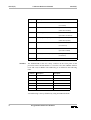
Jumpers
The delivered Boot EPROM is designed for the most common board
configuration.
For the EUROCOM-27 this corresponds to 8 MB RAM, graphics,
SCSI and network devices on board. If the board differs from this
combination, the standard Boot EPROM may hang up the system
(e.g. less memory or SCSI chip missing). If the system hangs, config.h
and/or eltec27.h must be modified and a new Boot EPROM must be
rebuilt. Do not mix up different versions of Boot EPROM and BSP
(e.g. Boot EPROM Version 5.11 - BSP Version 5.2).
The EUROCOM-27 is factory configured for immediate operation with
VxWorks. The table below lists the jumpers for the EUROCOM-27.
Starred settings (*) indicate the factory default and are appropriate for use
with VxWorks.
Programmers Reference Manual
1
eltec27(T)
VxWorks Reference Manual
Jumper
Description
J1201
Digclk inversion
eltec27(T)
(1-2 * not inverted)
(2-3 inverted)
J1202
TTL Video Outputs
(open * when disabled)
(closed when enabled)
J1401
Watchdog period
(closed * when 100 ms)
(open when 1.6 seconds)
J1601
Flash programming voltage
(open * when not present)
(closed when present)
J1605
Pin1 connection for EPROM
(1-2 * when 5 volts)
(2-3 when A19)
J1702
EEPROM write enable
(closed * when disabled)
(open when enabled)
J1801
Snooping of secondary computer
(1-2 * ignore)
(2-3 observe)
J1703
Switches
VMEbus Interrupts for secondary CPU
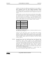
The EUROCOM-27 has two rotary switches on the front panel of the
processor board. Switch number 1 is used to select the VMEbus address
(A32 and A16) for RMon. The addressing is as defined in the following
table.
Position
A32 Space
A16 Space
F
0xF0000000
0xF000
E
0xE0000000
0xE000
D
0xD0000000
0xD000
2
0x20000000
0x2000
1
0x10000000
0x1000
0
RMon defined
RMon defined
A24 addressing is always disabled by using the RMon defaults.
2
Programmers Reference Manual
eltec27(T)
VxWorks Reference Manual
eltec27(T)
VxWorks can inherit the addressing assignments set up by RMon, if
desired. When VxWorks is built with the USE_RMON_CONFIG defined,
then
VxWorks
will
use
the
RMon
addressing.
When
USE_RMON_CONFIG is not defined, the addressing is set as per the
LOCAL_MEM_BUS_ADRS definition within config.h and the processor
number.
Switch number 2 is used to select the start up mode that is used by RMon.
For automatic transfer to the VxWorks programmed in the user EPROM,
this switch must be set to positions 8 - F. All other positions will not
perform an automatic start of VxWorks. When the VxWorks kernel is
built to include support for the selection of console port by switch, the
switch specifies the port to use for the VxWorks console, as follows:
Position
VxWorks_Device
8
/tyCo/0
9
/tyCo/1
A
/tyCo/2
B
/tyCo/3
C
/tyCo/4
To enable this operation the SELECT_CONSOLE_SWITCH must be
defined within the config.h file.
Switch S3 on the front panel is used to select VME system controller
functions. When the EUROCOM-27 is placed in slot 1 of the VME
chassis, the system controller option should be selected. When another
processor is placed in slot 1, then that processor will usually fulfil the
system controller function and the S3 should not select the system
controller function.
Devices
The eltecSerial.c Cirrus Logic CD2401 try driver is provided for the four
on-board serial ports; see the manual entry for tyCoDrv. The
eltecConsole.c driver provides support for the graphics/keyboard
interface. The console driver will inherit the characteristics of the monitor
as specified within the RMon monitor program. This includes the screen
dimensions and background/foreground colors. When the graphics/
keyboard support is selected when the VxWorks kernel is built, the
graphics/keyboard will be accessed as /tyCo/0 and the serial ports will be
accessed as /tyCo/1 through /tyCo/4.
The INCLUDE_GRAPHICS_KEYBOARD is defined within the
eltec27.h file to include the support for the console driver.
Programmers Reference Manual
3
eltec27(T)
VxWorks Reference Manual
eltec27(T)
The chip drivers included are:
•mk48TxxClock.c
•nvRam.c
•vic064Vme.c
•z8536Timer.c
- MK48Txx time keeper
- nonvolatile RAM
- Cypress VIC064 VME interface
- Zilog Counter/Timer Parallel I/O (CIO) timer
A network interface for the on-board ILACC chip allows VxWorks to run
without an additional network board. The interface is called “il” and
should be specified as the boot device to the boot ROMs.
A device driver for the NCR53C720 SCSI Input Output Processor (SIOP)
is provided. The INCLUDE_SCSI directive must be enabled in config.h.
Special Considerations
The ILACC chip needs to be informed of its Ethernet address before it can
attach to the LAN. The address is obtained from the RMon EPROM which
is unique for each board.
Console connection can be via any of the serial ports or the graphics/
keyboard interface. Selection of the console port is made through the
VxWorks kernel build process. When enabled the console port can be
selected via the setting of switch 2.
The NCR53C520 SCSI library supports SCSI wide and SCSI fast,
however, these features are currently not supported by the SCSI library.
Therefore, special functions are present to place a compatible SCSI device
in the fast and/or wide mode. See the manual pages for sysScsiMode for
additional information.
The EUROCOM-27 has a watchdog function that when enabled must be
triggered at a minimum of the frequency selected by the J1401 setting
(100 ms or 1.6 seconds). The INCLUDE_WDOG definition within
config.h enables this feature.
The VIC064 VME interface driver provides an optional VME DMA copy
function
which
is
enabled
by
the
inclusion
of
the
INCLUDE_VIC_BLK_XFER definition within the config.h file. See the
manual entry for sysVicBlkCopy for additional information on block
copies.
The MK48Txx time keeper module on the EUROCOM-27 can be used to
provide
system
time
for
VxWorks.
If
the
definition
INCLUDE_MK48TIME is defined in the config.h file, the time keeper
functions are included. The ANSI time support also needs to be included
within the VxWorks kernel which is the default. The definition
INCLUDE_ANSI_TIME controls the inclusion of the ANSI time
4
Programmers Reference Manual
eltec27(T)
VxWorks Reference Manual
eltec27(T)
functions. When the time keeper functions are included and the DOS file
system is also included, the DOS files are stamped with the date and time
as maintained by the MK48Txx.
Board Layout
The EUROCOM-27 does not have any jumpers that need be in set
positions for operation with VxWorks. Refer to the EUROCOM-27
technical manual for the locations of jumpers, switches, and EPROMs.
See Also
Programmer’s Guide: Getting Started,
Configuration RMon Monitor Program - Programmers Reference Manual,
RMon User Manual - Software Manual,
EUROCOM-27 Technical Manual
Programmers Reference Manual
5
sysLib(1)
VxWorks Reference Manual
sysLib(1)
sysLib(1)
Name
Synopsis
sysLib - ELTEC EUROCOM-27 system-dependent library
sysClockGet()
sysClockSet()
sysClockStop()
sysClockPrint()
sysNvRamGet()
sysNvRamSet()
sysIntDisable()
sysIntEnable()
sysBusIntAck()
sysBusIntGen()
sysMailboxConnect()
sysMailboxEnable()
sysVicBlkEnable()
sysVicBlkAdj()
sysVicBlkCopy()
sysVicShow()
sysClkConnect()
sysClkInt()
sysClkDisable()
sysClkEnable()
sysClkRateGet()
sysClkRateSet()
sysAuxClkConnect()
sysAuxClkDisable()
sysAuxClkEnable()
sysAuxClkRateGet()
sysAuxClkRateSet()
sysModel()
sysBspRev()
sysHwInit()
sysFrontPanelSwitch()
sysSetLed()
sysMemTop()
sysToMonitor()
sysLocalToBusAdrs()
sysBusToLocalAdrs()
6
get the contents of the clock
sets the nonvolatile clock
stops the nonvolatile clock
prints value stored in the nonvolatile clock
get the contents of nonvolatile RAM
write to nonvolatile RAM
disable a bus interrupt level
enable a bus interrupt level
acknowledge a bus interrupt
generate a bus interrupt
connect a routine to the mailbox interrupt
enable the mailbox interrupt
initialize the DMA copy operation for the
VIC064.
adjust burst length and interleave period for
DMA transfers
copy blocks over the VMEbus using the VIC’s
DMA feature
displays the contents of the VIC064 registers
connect a routine to the system clock interrupt
handle a system clock interrupt
turn off system clock interrupts
turn on system clock interrupts
get the system clock rate
set the system clock rate
connect a routine to the auxiliary clock interrupt
turn off auxiliary clock interrupts
turn on auxiliary clock interrupts
get the auxiliary clock rate
set the auxiliary clock rate
return the model name of the CPU board
return the bsp version with the revision e.g.
1.0/<x>
initialize the CPU board hardware
read the front panel switches
set value in LED
get the address of the top of memory
transfer control to the ROM monitor
convert a local address to a bus address
convert a bus address to a local address
Programmers Reference Manual
sysLib(1)
VxWorks Reference Manual
sysProcNumGet()
sysProcNumSet()
sysBusTas()
sysSysfailConnect()
sysAcfailConnect()
sysIlaccIntEnable()
sysLib(1)
get the processor number
set the processor number
test and set a location across the bus
connect a routine to the SYSFAIL signal
connect a routine to the ACFAIL signal
enable the ILACC interrupt level
time_t sysClockGet
(struct tm *time)
STATUS sysClockSet
(UINT8 date, UINT8 month, UINT8 year, UINT8 hour,
UINT8 minute, UINT8 second)
STATUS sysClockStop
(void)
STATUS sysClockPrint
(void)
STATUS sysNvRamGet
(char *string, int strLen, int offset)
STATUS sysNvRamSet
(char *string, int strLen, int offset)
STATUS sysIntDisable
(int intLevel)
STATUS sysIntEnable
(int intLevel)
int sysBusIntAck
(int intLevel)
STATUS sysBusIntGen
(int level, int vector)
STATUS sysMailboxConnect
(FUNCPTR routine, int arg)
STATUS sysMailboxEnable
(char *mailboxAdrs)
STATUS sysVicBlkEnable
(VOIDFUNCPTR * vector, int level, int burstLength,
int interleave)
STATUS sysVicBlkAdj
(int burstLength, int interleave)
STATUS sysVicBlkCopy
(char * localAddr, char * remoteAddr, int nbytes,
BOOL toVme, BOOL doD64)
intsysVicShow()
STATUS sysClkConnect
(FUNCPTR routine, int arg)
void sysClkInt
(void)
void sysClkDisable
(void)
Programmers Reference Manual
7
sysLib(1)
VxWorks Reference Manual
sysLib(1)
void sysClkEnable
(void)
int sysClkRateGet
(void)
STATUS sysClkRateSet
(int ticksPerSecond)
STATUS sysAuxClkConnect
(FUNCPTR routine, int arg)
void sysAuxClkDisable
(void)
void sysAuxClkEnable
(void)
int sysAuxClkRateGet
(void)
STATUS sysAuxClkRateSet
(int ticksPerSecond)
char *sysModel
(void)
char * sysBspRev
(void)
void sysHwInit
(void)
int sysFrontPanelSwitch
(int swNum)
int sysSetLed
(int hexVal)
char *sysMemTop
(void)
STATUS sysToMonitor
(int startType)
STATUS sysLocalToBusAdrs
(int adrsSpace, char *localAdrs, char **pBusAdrs)
STATUS sysBusToLocalAdrs
(int adrsSpace, char *busAdrs, char **pLocalAdrs)
int sysProcNumGet
(void)
void sysProcNumSet
(int procNum)
BOOL sysBusTas
(char *adrs)
STATUS sysSysfailConnect
(VOIDFUNCPTR routine, int arg)
STATUS sysAcfailConnect
(VOIDFUNCPTR routine, int arg)
int sysIlaccIntEnable
(int level)
8
Programmers Reference Manual
sysLib(1)
VxWorks Reference Manual
Description
This library provides board-specific routines. The chip drivers included
are:
•eltecSerial.c
•mk48TxxClock.c
•nvRam.c
•vic064Vme.c
•z8536Timer.c
Include Files
See Also
sysLib(1)
Cirrus CD2400 serial device module library
MK48Txx time keeper clock module library
nonvolatile RAM library
Cypress VIC068 VMEbus interface controller library
Zilog 8536 Counter/Timer device library
sysLib.h
Programmer’s Guide: Configuration
Programmers Reference Manual
9
if_il(1)
VxWorks Reference Manual
if_il(1)
if_il(1)
Name
Synopsis
if_il - AMD 79900 ILACC Ethernet network interface driver
ilattach() - publish the interface, and initialize the driver and device
STATUS ilattach
(int unit, char *devAdrs, int ivec, int ilevel,
char *memAdrs, ULONG memSize, int memWidth, int spare,
int spare2)
Description
General Information
This module implements the AMD 79900 ILACC Ethernet network
interface driver.
This driver is designed to achieve a moderate level of genericism, across
the range of architectures and targets that VxWorks 5.1 supports. This
allows the driver to be run, unmodified, on a variety of target hardware.
To achieve this goal, the driver must be given several target-specific
parameters, and some external support routines must be provided. These
parameters, and the mechanisms used to communicate them to the driver,
are detailed below. If any of the assumptions mentioned below are not true
for your particular hardware, this driver will probably not function
correctly. This driver supports only one ILACC unit per CPU. The driver
can be configured to support big-endian or little-endian architectures.
Board Layout
External Interface
This device is on-board. No jumpering diagram required.
This driver provides the standard external interface with the following
exceptions. All initialization is performed within the attach() routine and
there is no separate init() routine. Therefore, in the global interface
structure, the function pointer to the init() routine is NULL.
There is one user-callable routine: ilattach(). See the manual entry for this
routine for usage details.
Target Specific
Parameters
•bus mode
This parameter is globally accessed.
The ILACC control register #3 determines the bus mode of the device.
This allows the support of big-endian and little-endian architectures.
This parameter, defined as "u_short ilCSR_3B", is the value that will be
placed into ILACC control register #3. The default value supports
Motorola type busses. See the ILACC manual to change this parameter.
10
Programmers Reference Manual
if_il(1)
VxWorks Reference Manual
if_il(1)
•base address of device registers
This parameter is passed to the driver with the ilattach() routine.
The ILACC presents two registers to the external interface, the RDP
register, and the RAP register. This driver assumes that these two
registers occupy two unique addresses in a memory space that is directly
accessible by the CPU executing this driver. This driver assumes that the
RDP register is mapped at a lower address than the RAP register, and is
therefore considered the "base address".
This parameter indicates to the driver where to find the RDP register.
•interrupt vector
This parameter is passed to the driver with the ilattach() routine.
This driver configures the ILACC device to generate hardware
interrupts for various events within the device. Therefore, this driver
contains an interrupt handler routine. This driver will call the VxWorks
system function intConnect() to connect its interrupt handler to the
interrupt vector generated as a result of the ILACC interrupt.
•interrupt level
This parameter is passed to the driver with the ilattach() routine.
Some target hardware use additional interrupt controller devices to help
organize and service the various interrupt sources. This driver avoids all
board-specific knowledge of such devices. During the initialization of
this driver, an external routine is called to perform any board-specific
operations required to allow the servicing of an ILACC interrupt. This
routine is described below. This parameter is passed to the external
routine.
•shared memory address
This parameter is passed to the driver with the ilattach() routine.
The ILACC device is a DMA type of device and typically shares access
to some region of memory with the CPU. This driver is designed for
systems that directly share memory between the CPU and the ILACC.
This driver assumes that this shared memory is directly available to this
driver without any arbitration or timing concerns.
This parameter may be used to specify an explicit memory region for
use by the ILACC. This should be used on hardware that restricts the
ILACC to a particular memory region. The constant NONE may be used
to indicate that there are no memory limitations. In this case, the driver
will attempt to allocate the shared memory from the system space.
Programmers Reference Manual
11
if_il(1)
VxWorks Reference Manual
if_il(1)
•shared memory size
This parameter is passed to the driver with the ilattach() routine.
This parameter can be used to explicitly limit the amount of shared
memory (bytes) this driver will use. The constant NONE may be used to
indicate no specific size limitation. This parameter is only used if a
specific memory region is being provided to the driver.
•shared memory width
This parameter is passed to the driver with the ilattach() routine.
Some target hardware that restricts the shared memory region to a
specific location, also restricts the access width to this region by the
CPU. On these targets, performing an access of an invalid width will
cause a bus error.
This parameter can be used to specify the number of bytes of access
width to be used by the driver during access to the shared memory. The
constant NONE may be used to indicate no restrictions.
The current internal implementation of supporting this mechanism is not
robust, and may not work on all targets requiring these restrictions.
•shared memory buffer size
This parameter is passed to the driver with the ilattach() routine.
The driver and ILACC device exchange network data in buffers. This
parameter allows you to limit the size of these individual buffers. A
value of zero indicates that the default buffer size should be used. The
default buffer size is large enough to hold a maximum size Ethernet
packet.
Use of this parameter should be extremely rare. Network performance
will be affected, since the target will no longer be able to receive all
legal sizes of packets.
•Ethernet address
This parameter is obtained directly from a global memory location.
During initialization, the driver needs to know the Ethernet address for
the ILACC device. The driver assumes that this address is available in a
global, 6 byte, character array, named ilEnetAddr[]. This array is
typically created and stuffed by the BSP code.
12
Programmers Reference Manual
if_il(1)
VxWorks Reference Manual
External Support
Requirements
System Resource Usage
if_il(1)
This driver requires one external support routine to be provided.
•void sysIlaccIntEnable (int level)
This routine provides a target-specific enable of the interrupt for the
ILACC device. This typically involves interrupt controller hardware,
either internal or external to the CPU. This routine is called once from the
ilattach() routine.
The driver requires the following system resources:
•one mutual exclusion semaphore
•one interrupt vector
•5016 bytes in code section (text)
•28 bytes in the initialized data section (data)
•2244 bytes in the uninitialized data section (bss)
The sections are quoted for the MC68040 architecture and will vary for
other architectures.
If the driver allocates the memory to share with the ILACC, it does so by
calling the cacheDmaMalloc() routine. The size requested is 80,542 bytes.
If a memory region is provided to the driver, the size of this region is
adjustable to suit your needs.
The ILACC can only be operated if the shared memory region is writecoherent with regards to the data cache. The driver cannot maintain cache
coherency for the device for data that is written by the driver. This is
because fields within the shared structures are asynchronously modified
by both the driver, and the device, and these fields may share the same
cache line.
See Also
ifLib
Programmers Reference Manual
13
ncr720Lib(1)
VxWorks Reference Manual
ncr720Lib(1)
ncr720Lib(1)
Name
Synopsis
ncr720Lib - NCR53C720 SCSI I/O Processor (SIOP) library
ncr720CtrlCreate()
ncr720CtrlInit()
ncr720SetHwRegister()
ncr720Show()
- create a control structure for the SIOP
- initialize a control structure for the SIOP
- set hardware dependent registers
- display values of all readable ncr720 (SIOP)
registers
NCR_720_SCSI_CTRL *ncr720CtrlCreate
(UINT8 *baseAdrs, UINT freqValue)
STATUS ncr720CtrlInit
(NCR_720_SCSI_CTRL *pSiop, int scsiCtrlBusId,
int scsiPriority)
STATUS ncr720SetHwRegister
(SIOP *pSiop, NCR720_HW_REGS *pHwRegs)
STATUS ncr720Show
(SCSI_CTRL *pScsiCtrl)
Description
This is the I/O driver for the NCR53C720 SCSI I/O Processor (SIOP). It is
designed to work in conjunction with scsiLib. This driver runs in
conjunction with a script program for the NCR53C720 chip. The script
uses the NCR53C720 DMA function for data transfers. This driver
supports cache functions through cacheLib.
User Callable Routines
Most of the routines in this driver are accessible only through the I/O
system. Three routines, however, must be called directly:
ncr720CtrlCreate() to create a controller structure, and ncr720CtrlInit() to
initialize it. The NCR53C720 hardware registers need to be configured
according to the hardware implementation. If the default configuration is
not proper, the routine ncr720SetHwRegister() should be used to properly
configure the registers.
Include Files
See Also
14
ncr720.h, ncr720Script.h
scsiLib Programmer’s Guide: I/O System
Programmers Reference Manual
ncr720Lib(1)
VxWorks Reference Manual
ncr720Lib(1)
cd2400CoDevCreate() (2) create a device for an on-board serial port
cd2400CoDrv() (2)
tty driver initialization routine
eltecConDevCreate() (2) create a device for the keyboard and graphics
ports
eltecConDrv() (2)
console driver initialization routine
fbDisplay() (2)
display characters to the frame buffer
fbFlush() (2)
sets the entire screen to the specified color.
fbInitConsole() (2)
initialize the frame buffer for use with the
VxWorks console
fbLib (1)
Frame Buffer console library
fbSetColor() (2)
sets the foreground and background colors
if_il (1)
AMD 79900 ILACC Ethernet network
interface driver
ilattach() (2)
publish the interface, and initialize the driver
and device
ncr720CtrlCreate() (2)
create a control structure for the SIOP
ncr720CtrlInit() (2)
initialize a control structure for the SIOP
ncr720Lib (1)
NCR53C720 SCSI I/O Processor (SIOP)
library
ncr720SetHwRegister() (2) set hardware dependent registers
ncr720Show() (2)
display values of all readable ncr720 (SIOP)
registers
sysAcfailConnect() (2)
connect a routine to the ACFAIL signal
sysAuxClkConnect() (2) connect a routine to the auxiliary clock
interrupt
sysAuxClkDisable() (2) turn off auxiliary clock interrupts
sysAuxClkEnable() (2)
turn on auxiliary clock interrupts
sysAuxClkRateGet() (2) get the auxiliary clock rate
sysAuxClkRateSet() (2) set the auxiliary clock rate
sysBspRev() (2)
return the bsp version with the revision e.g.
1.0/<x>
sysBusIntAck() (2)
acknowledge a bus interrupt
sysBusIntGen() (2)
generate a bus interrupt
sysBusTas() (2)
test and set a location across the bus
sysBusToLocalAdrs() (2) convert a bus address to a local address
sysClkConnect() (2)
connect a routine to the system clock interrupt
sysClkDisable() (2)
turn off system clock interrupts
sysClkEnable() (2)
turn on system clock interrupts
sysClkInt() (2)
handle a system clock interrupt
sysClkRateGet() (2)
get the system clock rate
sysClkRateSet() (2)
set the system clock rate
sysClockGet() (2)
get the contents of the clock
sysClockPrint() (2)
prints value stored in the nonvolatile clock
sysClockSet() (2)
sets the nonvolatile clock
Programmers Reference Manual
15
ncr720Lib(1)
VxWorks Reference Manual
sysClockStop() (2)
sysFrontPanelSwitch() (2)
sysHwInit() (2)
sysIlaccIntEnable() (2)
sysIntDisable() (2)
sysIntEnable() (2)
sysLib (1)
ncr720Lib(1)
stops the nonvolatile clock
read the front panel switches
initialize the CPU board hardware
enable the ILACC interrupt level
disable a bus interrupt level
enable a bus interrupt level
ELTEC EUROCOM-27 system-dependent
library
sysLocalToBusAdrs() (2) convert a local address to a bus address
sysMailboxConnect() (2) connect a routine to the mailbox interrupt
sysMailboxEnable() (2) enable the mailbox interrupt
sysMemTop() (2)
get the address of the top of memory
sysModel() (2)
return the model name of the CPU board
sysNvRamGet() (2)
get the contents of nonvolatile RAM
sysNvRamSet() (2)
write to nonvolatile RAM
sysProcNumGet() (2)
get the processor number
sysProcNumSet() (2)
set the processor number
sysScsiInit() (2)
initialize NCR720 SCSI chip
sysScsiMode() (2)
change the SCSI mode for a target
sysSetLed() (2)
set value in LED
sysSysfailConnect() (2)
connect a routine to the SYSFAIL signal
sysToMonitor() (2)
transfer control to the ROM monitor
sysVicBlkAdj() (2)
adjust burst length and interleave period for
DMA transfers
sysVicBlkCopy() (2)
copy blocks over the VMEbus using the VIC’s
DMA feature
sysVicBlkEnable() (2)
initialize the DMA copy operation for the
VIC064
sysVicShow() (2)
displays the contents of the VIC064 registers
tyCoDevCreate() (2)
create a device for an on-board serial port
tyCoDrv (1)
ELTEC EUROCOM-27 tty driver
tyCoDrv() (2)
initialize the tty driver
16
Programmers Reference Manual
tyCoDrv(1)
VxWorks Reference Manual
tyCoDrv(1)
tyCoDrv(1)
Name
Synopsis
tyCoDrv - ELTEC EUROCOM-27 tty driver
cd2400CoDrv()
cd2400CoDevCreate()
tyCoDrv()
tyCoDevCreate()
- tty driver initialization routine
- create a device for an on-board serial port
- initialize the tty driver
- create a device for an on-board serial port
STATUS cd2400CoDrv
(void)
STATUS cd2400CoDevCreate
(char * name, int channel, int rdBufSize,
int wrtBufSize)
STATUS tyCoDrv
(void)
STATUS tyCoDevCreate
(char *name, int channel, int rdBufSize, int wrtBufSize)
Description
This is the driver for the ELTEC tty driver. It provides support for the
Cirrus Logic CD2400 MPCC and the graphics/keyboard interfaces. The
graphics/keyboard interface is treated as /tyCo/0 and the CD2400 ports
start at /tyCo/1. The driver uses the CD2400 only in asynchronous mode.
User-callable Routines
Most of the routines in this driver are accessible only through the I/O
system. Two routines, however, must be called directly: tyCoDrv() to
initialize the driver, and tyCoDevCreate() to create devices.
Before the driver can be used, it must be initialized by calling tyCoDrv().
This routine should be called exactly once, before any reads, writes, or
calls to tyCoDevCreate(). Normally, it is called from usrRoot() in
usrConfig.c. Before a terminal can be used, it must be created using
tyCoDevCreate(). Each port to be used should have exactly one device
associated with it by calling this routine.
Ioctl Functions
This CD2401 driver responds to the same ioctl() codes as a normal tty
driver; for more information, see the manual entry for tyLib. The available
baud rates are: 50, 110, 150, 300, 600, 1200, 2400, 3600, 4800, 7200,
9600, 19200, and 38400. In addition, the character size and parity is
selected using the FIOBAUDRATE ioctl. The argument to the ioctl call,
specifies the baud rate, character size, and parity. Bits 0-15 specify the
baud rate, bits 26 and 27 specify the parity (0 = none, 1 = odd, and 2 =
even), and bits 28 - 31 specify the character size (size of zero is use the
default). The graphics/keyboard device responds to the same ioctl() codes
as a normal tty driver.
See Also
tyLib
Programmers Reference Manual
17
fbLib(1)
VxWorks Reference Manual
fbLib(1)
fbLib(1)
Name
Synopsis
fbLib - Frame Buffer console library
fbInitConsole() - initialize the frame buffer for use with the VxWorks
console
fbSetColor()
- sets the foreground and background colors
fbFlush()
- sets the entire screen to the specified color.
fbDisplay()
- display characters to the frame buffer
STATUS fbInitConsole
(CON_DEV *dev, int baseAdrs, int height, int width)
VOID fbSetColor
(CON_DEV *dev, char bgColor, char fgColor)
VOID fbFlush
(CON_DEV *dev, char color)
VOID fbDisplay
(CON_DEV *dev, char outChar)
18
Programmers Reference Manual
cd2400CoDevCreate(2)
VxWorks Reference Manual
cd2400CoDevCreate(2)
cd2400CoDevCreate(2)
Name
Synopsis
Description
cd2400CoDevCreate() - create a device for an on-board serial port
STATUS cd2400CoDevCreate
(
char * name,
/*
int
channel,
/*
int
rdBufSize, /*
int
wrtBufSize /*
)
name to use for this device
physical channel for this device
read buffer size, in bytes
write buffer size, in bytes
*/
*/
*/
*/
This routine creates a device on a specified serial port. Each port to be
used should have exactly one device associated with it by calling this
routine.
For instance, to create the device "/tyCo/0", with buffer sizes of 512 bytes,
the proper call would be:
tyCoDevCreate ("/tyCo/0", 0, 512, 512);
Returns
OK, or ERROR if the driver is not installed or the channel is invalid.
See Also
tyCoDrv
Programmers Reference Manual
19
cd2400CoDrv(2)
VxWorks Reference Manual
cd2400CoDrv(2)
cd2400CoDrv(2)
Name
Synopsis
Description
cd2400CoDrv() - tty driver initialization routine
STATUS cd2400CoDrv (void)
This routine initializes the serial driver, sets up interrupt vectors, and
performs hardware initialization of the serial ports.
This routine should be called exactly once, before any reads, writes, or
calls to tyCoDevCreate(). Normally, it is called by usrRoot() in
usrConfig.c.
20
Returns
OK, or ERROR if the driver cannot be installed.
See Also
tyCoDrv
Programmers Reference Manual
eltecConDevCreate(2)
VxWorks Reference Manual
eltecConDevCreate(2)
eltecConDevCreate(2)
Name
Synopsis
Description
eltecConDevCreate() - create a device for the keyboard and graphics ports
STATUS eltecConDevCreate
(
char * name,
int
rdBufSize,
int
wrtBufSize,
int
fbBaseAdrs,
UINT16 width,
UINT16 height,
UINT8
fgColor,
UINT8
bgColor
)
/*
/*
/*
/*
/*
/*
/*
/*
Name to use for this device
Read buffer size, in bytes
Write buffer size in bytes
base address of frame buffer
width of screen
height of screen
background color
foreground color
*/
*/
*/
*/
*/
*/
*/
*/
This routine creates a device for keyboard and graphics ports.
Returns
OK or ERROR if no driver or already exists.
See Also
tyCoDrv
Programmers Reference Manual
21
eltecConDrv(2)
VxWorks Reference Manual
eltecConDrv(2)
eltecConDrv(2)
Name
Synopsis
Description
22
eltecConDrv() - console driver initialization routine
STATUS eltecConDrv (void)
This routine initializes the console driver, sets up interrupt vectors, and
performs hardware initialization of the keyboard and display.
Returns
OK or ERROR if unable to install driver.
See Also
tyCoDrv
Programmers Reference Manual
fbDisplay(2)
VxWorks Reference Manual
fbDisplay(2)
fbDisplay(2)
Name
Synopsis
Description
fbDisplay() - display characters to the frame buffer
VOID fbDisplay
(
CON_DEV *dev,
char
outChar
)
/* device descriptor
*/
/* character to display */
This routine converts the requested characters to the required pixels within
the frame buffer.
Returns
N/A
See Also
fbLib
Programmers Reference Manual
23
fbFlush(2)
VxWorks Reference Manual
fbFlush(2)
Name
Synopsis
Description
24
fbFlush() - sets the entire screen to the specified color.
VOID fbFlush
(
CON_DEV *dev,
char
color
)
/* device descriptor */
/* color
*/
This routine sets the entire screen to the specified color.
Returns
N/A
See Also
fbLib
Programmers Reference Manual
fbFlush(2)
fbInitConsole(2)
VxWorks Reference Manual
fbInitConsole(2)
fbInitConsole(2)
Name
Synopsis
Description
fbInitConsole() - initialize the frame buffer for use with the VxWorks
console
STATUS fbInitConsole
(
CON_DEV *dev,
int
baseAdrs,
int
height,
int
width
)
/*
/*
/*
/*
device descriptor
*/
base address of frame buffer */
height of screen
*/
width of screen
*/
This routine initializes the frame buffer console library.
Returns
OK or ERROR if unable to initialize the frame buffer.
See Also
fbLib
Programmers Reference Manual
25
fbSetColor(2)
VxWorks Reference Manual
fbSetColor(2)
fbSetColor(2)
Name
Synopsis
Description
26
fbSetColor() - sets the foreground and background colors
VOID fbSetColor
(
CON_DEV *dev,
char
bgColor,
char
fgColor
)
/* device descriptor */
/* background color */
/* foreground color */
This routine sets the foreground and background colors for the display.
Returns
N/A
See Also
fbLib
Programmers Reference Manual
ilattach(2)
VxWorks Reference Manual
ilattach(2)
ilattach(2)
Name
Synopsis
Description
ilattach() - publish the interface, and initialize the driver and device
STATUS ilattach
(
int
unit,
char
*devAdrs,
int
ivec,
int
ilevel,
char
*memAdrs,
/*
/*
/*
/*
/*
ULONG
memSize,
/*
int
memWidth,
/*
int
int
)
spare,
spare2
/*
/*
unit number */
ILACC i/o address */
interrupt vector */
interrupt level */
address of memory pool
(-1 == malloc it) */
only used if memory pool is NOT
malloced */
byte-width of data
(-1 == any width) */
not used */
not used */
The routine publishes the "il" interface by filling in a network interface
record and adding this record to the system list. This routine also
initializes the driver and the device to the operational state.
The <memAdrs> parameter can be used to specify the location of the
memory that will be shared between the driver and the device. The value
NONE may be used to indicate that the driver should obtain the memory.
The <memSize> parameter is only valid if the <memAdrs> parameter is
not set to NONE. In this case, this parameter indicates the size of the
provided memory region.
The <memWidth> parameter sets the memory pool’s data port width (in
bytes); if NONE, any data width will be used.
Returns
OK or ERROR.
See Also
if_il
Programmers Reference Manual
27
ncr720CtrlCreate(2)
VxWorks Reference Manual
ncr720CtrlCreate(2)
ncr720CtrlCreate(2)
Name
Synopsis
Description
ncr720CtrlCreate() - create a control structure for the SIOP
NCR_720_SCSI_CTRL *ncr720CtrlCreate
(
UINT8 *baseAdrs, /* base address of the SIOP */
UINT
freqValue
/* clock controller
*/
)
This routine creates an SIOP data structure and must be called before
using an SIOP chip. It should be called only once for a given SIOP. Since
it allocates memory for a structure needed by all routines in ncr720Lib, it
must be called before any other routines in the library. After calling this
routine, at least one call to ncr720CtrlInit() should be performed before
any SCSI transactions are initiated using the SIOP.
A detailed description of the input parameters follows:
28
<baseAdrs>
The address at which the CPU would access the lowest
register of the SIOP.
<freqValue>
The value at the SIOP SCSI CLK input. This is used to
determine the clock period for the scsi core of the chip
and the synchronous divider value for synchronous
transfer. It is important to have the right timing on the
SCSI bus.
Returns
A pointer to NCR_720_SCSI_CTRL structure, or NULL if memory is
unavailable or there are bad parameters.
See Also
ncr720Lib
Programmers Reference Manual
ncr720CtrlInit(2)
VxWorks Reference Manual
ncr720CtrlInit(2)
ncr720CtrlInit(2)
Name
Synopsis
Description
ncr720CtrlInit() - initialize a control structure for the SIOP
STATUS ncr720CtrlInit
(
NCR_720_SCSI_CTRL *pSiop,
/* ptr to SIOP struct */
int
scsiCtrlBusId, /* SCSI bus ID of this
SIOP */
int
scsiPriority
/* priority of a task
when doing SCSI I/O */
)
This routine initializes an SIOP structure, after the structure is created
with ncr720CtrlCreate(). This structure must be initialized before the
SIOP can be used. It may be called more than once if needed; however, it
should only be called while there is no activity on the SCSI interface.
Before using the SIOP, it must be initialized by calling this routine.
Before returning, this routine pulses RST (reset) on the SCSI bus, thus
resetting all attached devices.
A detailed description of the input parameters follows:
<pSiop>
a pointer to the NCR_720_SCSI_CTRL structure
created with ncr720CtrlCreate().
<scsiCtrlBusId> the SCSI bus ID of the SIOP. Its value is somewhat
arbitrary: seven (7), or highest priority, is conventional.
The value must be in the range 0 - 7.
<scsiPriority>
the priority to which a task is set when performing a
SCSI transaction. Legal priorities are 0 to 255.
Alternately, a -1 indicates that the priority should not be
altered during SCSI transactions.
Returns
OK, or ERROR if parameters are out of range.
See Also
ncr720Lib
Programmers Reference Manual
29
ncr720SetHwRegister(2)
VxWorks Reference Manual
ncr720SetHwRegister(2)
ncr720SetHwRegister(2)
Name
Synopsis
ncr720SetHwRegister() - set hardware dependent registers
STATUS ncr720SetHwRegister
(
SIOP
*pSiop,
NCR720_HW_REGS *pHwRegs
/* Pointer to SIOP infos */
/* Pointer to a NCR720_HW_REGS
info */
)
Description
This routine is used to set up the registers involved in the hardware
implementation of the chip. Typically, this routine is called by the
sysScsiInit() routine from the bsp. The input parameters are the pointer
returned by ncr720CtrlCreate() and a pointer to a NCR720_HW_REGS
structure that is filled with the logical values 0 or 1 for each bit of each
register describe below. This routine includes only the bit registers that
could modify the behavior of the chip. The default configuration used
during ncr720CtlrCreate(), and ncr720CrtlInit() is
{0,0,0,0,1,0,0,0,0,0,0,0,0,1,0}
typedef struct
{
int ctest4Bit7;
int ctest0Bit7;
int ctest0Bit6;
int ctest0Bit5;
int ctest0Bit1;
int ctest2Bit5;
int ctest3Bit0;
int dmodeBit7;
int dmodeBit6;
int dmodeBit5;
int dmodeBit4;
int dmodeBit3;
int dmodeBit1;
int dcntlBit5;
int dcntlBit1;
} NCR720_HW_REGS;
/*
/*
/*
/*
/*
/*
/*
/*
/*
/*
/*
/*
/*
/*
/*
Host bus multiplex mode */
Disable/enable burst cache capability */
Snoop control bit1 */
Snoop control bit0 */
invert tt1 pin (sync bus host mode only)*/
enable differential scsi bus capability*/
Set snoop pins mode */
Burst Length transfer bit 1 */
Burst Length transfer bit 0 */
Function code bit FC2 */
Function code bit FC1 */
Program data bit (FC0) */
user programmable transfer type */
Enable Ack pin */
Enable fast arbitration on host port */
To get a more detailed explanation regarding the description of each
register involved see the User’s Manual of the NCR53C720.
Note
30
Because this routine writes to the chip registers you can't use it if there is
any SCSI bus activity.
Returns
OK or ERROR if any input parameter is NULL.
See Also
ncr720Lib, ncr720.h, ncr720CtlrCreate()
Programmers Reference Manual
ncr720Show(2)
VxWorks Reference Manual
ncr720Show(2)
ncr720Show(2)
Name
Synopsis
ncr720Show() - Display values of all readable ncr720 (SIOP) registers
STATUS ncr720Show
(
SCSI_CTRL *pScsiCtrl
)
/* ptr to SCSI controller info */
Description
Displays the state of the SIOP registers in a user-friendly way. Primarily
used during debugging. The input parameter is the pointer to the SIOP
info structure returned by the ncr720CtrlCreate() call.
Note
The only readable register during a script execution is Istat register. If you
use this routine during the execution of a SCSI command the result will be
unpredictable.
Example
-> ncr720Show
NCR720 Registers
---------------0xfff47000: Scntl3 =
0xfff47004: Gpreg
=
0xfff47008: Sbcl
=
0xfff4700c: Sstat2 =
0xfff47010: Dsa
=
0xfff47014: Istat
=
0xfff47018: Ctest3 =
0xfff4701c: Temp
=
0xfff47020: Ctest6 =
0xfff47024: Dcmd/Ddc=
0xfff47028: Dnad
=
0xfff4702c: Dsp
=
0xfff47030: Dsps
=
0xfff47034: Scratch3=
0xfff47038: Dcntl
=
0xfff4703c: Adder
=
0xfff47040: Sist1
=
0xfff47046: Gpcntl =
0xfff4704a: RespID =
0xfff4704c: Stest3 =
0xfff47052: Sidl
=
0xfff47056: Sodl
=
0xfff4705a: Ssbdl
=
0xfff4705c: ScracthB=
value = 0 = 0x0
0xa5 Scntl2 =
0x00 Sdid
=
0x00 Ssid
=
0x00 Sstat1 =
0x00000000
0x00
0x00 Ctest2 =
0x00000000
0x00 Ctest5 =
0x50000000
0x00066144
0x00066144
0x00066174
0x00 Scratch2=
0x21 Dwt
=
0x000cc2b8
0x00 Sist1
=
0x00 Macntl =
0x00 Stest2
0x0000
0x0000
0x0000
0x00000000
0x00
0x00
0x00
0x00
Scntl1
Sxfer
Socl
Sstat0
=
=
=
=
0x00
0x80
0x00
0x00
Scntl0
Scid
Sfbr
Dstat
=
=
=
=
0x04
0x80
0x00
0x80
0x21 Ctest1
= 0xf0 Ctest0
= 0x00
0x00 Ctest4
= 0x00 Dfifo
= 0x00
0x00 Scratch1= 0x00 Scratch0= 0x0a
0x00 Dien
= 0x37 Dmode
= 0x01
0x00 Sien1
0x00 Swide
Stime1
= 0x00 Stest1
=
=
=
=
0x00
0x00
0x00
0x00
Sien0
Slpar
Stime0
Stest0
=
=
=
=
0x00
0x00
0x00
0x00
See Also
ncr720Lib, ncr720CtrlCreate()
Returns
OK, or ERROR if <pScsiCtrl> and <pSysScsiCtrl> are both NULL.
Programmers Reference Manual
31
sysAcfailConnect(2)
VxWorks Reference Manual
sysAcfailConnect(2)
sysAcfailConnect(2)
Name
Synopsis
sysAcfailConnect() - connect a routine to the ACFAIL signal
STATUS sysAcfailConnect
(
VOIDFUNCPTR routine,
int
arg
/* routine to be connected to
ACFAIL signal */
/* argument with which to call
routine */
)
Description
32
This routine connects a specified routine to the board’s ACFAIL signal.
Returns
OK, or ERROR if the routine cannot be connected to the interrupt.
See Also
sysLib, intConnect()
Programmers Reference Manual
sysAuxClkConnect(2)
VxWorks Reference Manual
sysAuxClkConnect(2)
sysAuxClkConnect(2)
Name
Synopsis
Description
sysAuxClkConnect() - connect a routine to the auxiliary clock interrupt
STATUS sysAuxClkConnect
(
FUNCPTR routine, /* routine called at each aux clock
interrupt */
int
arg
/* argument with which to call
routine */
)
This routine specifies the interrupt service routine to be called at each
auxiliary clock interrupt. It also connects the clock error interrupt service
routine.
Returns
OK, or ERROR if the routine cannot be connected to the interrupt.
See Also
sysLib, intConnect(), sysAuxClkEnable()
Programmers Reference Manual
33
sysAuxClkDisable(2)
VxWorks Reference Manual
sysAuxClkDisable(2)
sysAuxClkDisable(2)
Name
Synopsis
Description
34
sysAuxClkDisable() - turn off auxiliary clock interrupts
void sysAuxClkDisable (void)
This routine disables auxiliary clock interrupts.
Returns
N/A
See Also
sysLib, sysAuxClkEnable()
Programmers Reference Manual
sysAuxClkEnable(2)
VxWorks Reference Manual
sysAuxClkEnable(2)
sysAuxClkEnable(2)
Name
Synopsis
Description
sysAuxClkEnable() - turn on auxiliary clock interrupts
void sysAuxClkEnable (void)
This routine enables auxiliary clock interrupts.
Returns
N/A
See Also
sysLib, sysAuxClkDisable()
Programmers Reference Manual
35
sysAuxClkRateGet(2)
VxWorks Reference Manual
sysAuxClkRateGet(2)
sysAuxClkRateGet(2)
Name
Synopsis
Description
36
sysAuxClkRateGet() - get the auxiliary clock rate
int sysAuxClkRateGet (void)
This routine returns the interrupt rate of the auxiliary clock.
Returns
The number of ticks per second of the auxiliary clock.
See Also
sysLib, sysAuxClkEnable(), sysAuxClkRateSet()
Programmers Reference Manual
sysAuxClkRateSet(2)
VxWorks Reference Manual
sysAuxClkRateSet(2)
sysAuxClkRateSet(2)
Name
Synopsis
sysAuxClkRateSet() - set the auxiliary clock rate
STATUS sysAuxClkRateSet
(
int ticksPerSecond
/* number of clock interrupts per
second */
)
Description
This routine sets the interrupt rate of the auxiliary clock. If the auxiliary
clock is currently enabled, the clock is disabled and then re-enabled with
the new rate.
Returns
OK or ERROR.
See Also
sysLib, sysAuxClkEnable(), sysAuxClkRateGet()
Programmers Reference Manual
37
sysBspRev(2)
VxWorks Reference Manual
sysBspRev(2)
sysBspRev(2)
Name
Synopsis
Description
38
sysBspRev() - return the bsp version with the revision e.g. 1.0/<x>
char * sysBspRev (void)
This function returns a pointer to a bsp version with the revision e.g.
1.0/<x>.
BSP_REV defined in config.h is concatenated to BSP_VERSION defined
in bspVersion.h and returned.
Returns
A pointer to the BSP version/revision string.
See Also
sysLib
Programmers Reference Manual
sysBusIntAck(2)
VxWorks Reference Manual
sysBusIntAck(2)
sysBusIntAck(2)
Name
Synopsis
Description
sysBusIntAck() - acknowledge a bus interrupt
int sysBusIntAck
(
int intLevel
)
/* interrupt level to acknowledge */
This routine acknowledges a specified VMEbus interrupt level. The
VIC064 performs this function automatically.
Returns
NULL. Performed by hardware.
See Also
sysLib, sysBusIntGen()
Programmers Reference Manual
39
sysBusIntGen(2)
VxWorks Reference Manual
sysBusIntGen(2)
sysBusIntGen(2)
Name
Synopsis
40
sysBusIntGen() - generate a bus interrupt
STATUS sysBusIntGen
(
int level, /* VMEbus interrupt level to generate
(1-7) */
int vector /* interrupt vector to generate (0-255) */
)
Description
This routine generates a bus interrupt for a specified level with a specified
vector.
Returns
OK, ERROR if interrupt level out of range (1 - 7) or vector is out of range
(0 - 255) or a previous unacknowledged interrupt is pending.
See Also
sysLib, sysBusIntAck()
Programmers Reference Manual
sysBusTas(2)
VxWorks Reference Manual
sysBusTas(2)
sysBusTas(2)
Name
Synopsis
Description
sysBusTas() - test and set a location across the bus
BOOL sysBusTas
(
char *adrs
)
/* address to be tested and set */
This routine performs a 680x0 test-and-set instruction across the
backplane.
Returns
TRUE (successful set), or FALSE (failure).
See Also
sysLib, vxTas()
Programmers Reference Manual
41
sysBusToLocalAdrs(2)
VxWorks Reference Manual
sysBusToLocalAdrs(2)
sysBusToLocalAdrs(2)
Name
Synopsis
42
sysBusToLocalAdrs() - convert a bus address to a local address
STATUS sysBusToLocalAdrs
(
int
adrsSpace,
/* bus address space in which busAdrs
resides */
char *busAdrs,
/* bus address to convert */
char **pLocalAdrs /* where to return local address */
)
Description
This routine gets the local address that accesses a specified VMEbus
address.
Returns
OK, or ERROR if the address space is unknown or the mapping is not
possible.
See Also
sysLib, sysLocalToBusAdrs()
Programmers Reference Manual
sysClkConnect(2)
VxWorks Reference Manual
sysClkConnect(2)
sysClkConnect(2)
Name
Synopsis
sysClkConnect() - connect a routine to the system clock interrupt
STATUS sysClkConnect
(
FUNCPTR routine,
int
arg
/* routine called at each system clock
interrupt*/
/* argument with which to call
routine */
)
Description
This routine specifies the interrupt service routine to be called at each
clock interrupt. It is called from usrRoot() in usrConfig.c to connect
usrClock() to the system clock interrupt. It also connects the clock error
interrupt service routine.
Returns
OK, or ERROR if the routine cannot be connected to the interrupt.
See Also
sysLib, intConnect(), usrClock(), sysClkEnable()
Programmers Reference Manual
43
sysClkDisable(2)
VxWorks Reference Manual
sysClkDisable(2)
Name
Synopsis
Description
44
sysClkDisable() - turn off system clock interrupts
void sysClkDisable (void)
This routine disables system clock interrupts.
Returns
N/A
See Also
sysLib, sysClkEnable()
Programmers Reference Manual
sysClkDisable(2)
sysClkEnable(2)
VxWorks Reference Manual
sysClkEnable(2)
sysClkEnable(2)
Name
Synopsis
Description
sysClkEnable() - turn on system clock interrupts
void sysClkEnable (void)
This routine enables system clock interrupts.
Returns
N/A
See Also
sysLib, sysClkConnect(), sysClkDisable(), sysClkRateSet()
Programmers Reference Manual
45
sysClkInt(2)
VxWorks Reference Manual
sysClkInt(2)
sysClkInt(2)
Name
Synopsis
Description
See Also
46
sysClkInt() - handle a system clock interrupt
void sysClkInt (void)
This routine handles a system clock interrupt. It acknowledges the
interrupt and calls the routine installed by sysClkConnect().
sysLib
Programmers Reference Manual
sysClkRateGet(2)
VxWorks Reference Manual
sysClkRateGet(2)
sysClkRateGet(2)
Name
Synopsis
Description
sysClkRateGet() - get the system clock rate
int sysClkRateGet (void)
This routine returns the interrupt rate of the system clock.
Returns
The number of ticks per second of the system clock.
See Also
sysLib, sysClkEnable(), sysClkRateSet()
Programmers Reference Manual
47
sysClkRateSet(2)
VxWorks Reference Manual
sysClkRateSet(2)
sysClkRateSet(2)
Name
Synopsis
sysClkRateSet() - set the system clock rate
STATUS sysClkRateSet
(
int ticksPerSecond
/* number of clock interrupts per
second */
)
Description
48
This routine sets the interrupt rate of the system clock. The new interrupt
rate is saved. If the system clock is currently enabled, the clock is disabled
and then re-enabled with the new rate. This routine is called by usrRoot()
in usrConfig.c.
Note
The valid range for the system clock is 40 to 5000 ticks per second.
Returns
OK, or ERROR if the tick rate is invalid or the timer cannot be set.
See Also
sysLib, sysClkEnable(), sysClkRateGet()
Programmers Reference Manual
sysClockGet(2)
VxWorks Reference Manual
sysClockGet(2)
sysClockGet(2)
Name
Synopsis
Description
sysClockGet() - get the contents of the clock
time_t sysClockGet
(
struct tm *time
)
This routine copies the time from the time keeper device into the time
structure provided as the input argument (see time.h). The function will
automatically calculate the day of the week from the time provided in the
time keeper device.
Returns
ERROR, if time keeper is not running; otherwise the calendar time.
See Also
sysLib, sysClockSet(), sysClockStop()
Programmers Reference Manual
49
sysClockPrint(2)
VxWorks Reference Manual
sysClockPrint(2)
sysClockPrint(2)
Name
Synopsis
Description
50
sysClockPrint() - prints value stored in the nonvolatile clock
STATUS sysClockPrint (void)
This routine prints the specified time as set in the nonvolatile clock.
Returns
OK
See Also
sysLib, sysClockGet()
Programmers Reference Manual
sysClockSet(2)
VxWorks Reference Manual
sysClockSet(2)
sysClockSet(2)
Name
Synopsis
Description
sysClockSet() - sets the nonvolatile clock
STATUS sysClockSet
(
UINT8 date,
UINT8 month,
UINT8 year,
UINT8 hour,
UINT8 minute,
UINT8 second
)
/*
/*
/*
/*
/*
/*
date (1 - 31)
month (1 - 12)
year (0 - 99)
hours (0 - 23)
minute (0 - 59)
seconds (0 - 59)
*/
*/
*/
*/
*/
*/
This routine sets the clock to the specified time. If the clock was stopped,
this function will start the clock.
Returns
OK
See Also
sysLib, sysClockGet(), sysClockStop()
Programmers Reference Manual
51
sysClockStop(2)
VxWorks Reference Manual
sysClockStop(2)
sysClockStop(2)
Name
Synopsis
Description
52
sysClockStop() - stops the nonvolatile clock
STATUS sysClockStop (void)
This routine stops the nonvolatile clock such that the clock battery can be
conserved.
Returns
OK
See Also
sysLib, sysClockSet()
Programmers Reference Manual
sysFrontPanelSwitch(2)
VxWorks Reference Manual
sysFrontPanelSwitch(2)
sysFrontPanelSwitch(2)
Name
Synopsis
Description
sysFrontPanelSwitch() - read the front panel switches
int sysFrontPanelSwitch
(
int swNum /* switch number to read */
)
This routine returns the value of the specified front panel switch.
Returns
Value that switch is set to.
See Also
sysLib
Programmers Reference Manual
53
sysHwInit(2)
VxWorks Reference Manual
sysHwInit(2)
sysHwInit(2)
Name
Synopsis
Description
Note
54
sysHwInit() - initialize the CPU board hardware
void sysHwInit (void)
This routine initializes various features of the CPU board hardware. It is
called from usrInit() in usrConfig.c.
This routine should not be called by the user.
Returns
N/A
See Also
sysLib
Programmers Reference Manual
sysIlaccIntEnable(2)
VxWorks Reference Manual
sysIlaccIntEnable(2)
sysIlaccIntEnable(2)
Name
Synopsis
Description
sysIlaccIntEnable() - enable the ILACC interrupt level
int sysIlaccIntEnable
(
int level /* interrupt level, not used */
)
This routine enables interrupts for the on-board ILACC chip at a specified
level. ILACC interrupts are controlled by the VIC chip. The VIC chip also
provides the interrupt vector.
Returns
OK
See Also
sysLib
Programmers Reference Manual
55
sysIntDisable(2)
VxWorks Reference Manual
sysIntDisable(2)
sysIntDisable(2)
Name
Synopsis
Description
56
sysIntDisable() - disable a bus interrupt level
STATUS sysIntDisable
(
int intLevel /* interrupt level to disable (1-7) */
)
This routine disables a specified VMEbus interrupt level.
Returns
OK, or ERROR if <intLevel> is not in the range 1 - 7.
See Also
sysLib, sysIntEnable()
Programmers Reference Manual
sysIntEnable(2)
VxWorks Reference Manual
sysIntEnable(2)
sysIntEnable(2)
Name
Synopsis
Description
sysIntEnable() - enable a bus interrupt level
STATUS sysIntEnable
(
int intLevel /* interrupt level to enable (1-7) */
)
This routine enables a specified VMEbus interrupt level.
Returns
OK, or ERROR if <intLevel> is not in the range 1 - 7.
See Also
sysLib, sysIntDisable()
Programmers Reference Manual
57
sysLocalToBusAdrs(2)
VxWorks Reference Manual
sysLocalToBusAdrs(2)
sysLocalToBusAdrs(2)
Name
Synopsis
Description
58
sysLocalToBusAdrs() - convert a local address to a bus address
STATUS sysLocalToBusAdrs
(
int
adrsSpace,
/* bus address space in which busAdrs
resides */
char *localAdrs, /* local address to convert */
char **pBusAdrs
/* where to return bus address */
)
This routine gets the VMEbus address that accesses a specified local
memory address.
Returns
OK, or ERROR if the mapping is not possible.
See Also
sysLib, sysBusToLocalAdrs()
Programmers Reference Manual
sysMailboxConnect(2)
VxWorks Reference Manual
sysMailboxConnect(2)
sysMailboxConnect(2)
Name
Synopsis
Description
sysMailboxConnect() - connect a routine to the mailbox interrupt
STATUS sysMailboxConnect
(
FUNCPTR routine, /* routine called at each mailbox
interrupt */
int
arg
/* argument with which to call
routine */
)
This routine specifies the interrupt service routine to be called at each
mailbox interrupt.
Returns
OK, always
See Also
sysLib, intConnect(), sysMailboxEnable()
Programmers Reference Manual
59
sysMailboxEnable(2)
VxWorks Reference Manual
sysMailboxEnable(2)
sysMailboxEnable(2)
Name
Synopsis
Description
60
sysMailboxEnable() - enable the mailbox interrupt
STATUS sysMailboxEnable
(
char *mailboxAdrs /* address of mailbox (ignored) */
)
This routine enables the ICMS-0 mailbox on the VIC064.
Returns
OK, always.
See Also
sysLib, sysMailboxConnect()
Programmers Reference Manual
sysMemTop(2)
VxWorks Reference Manual
sysMemTop(2)
sysMemTop(2)
Name
Synopsis
Description
sysMemTop() - get the address of the top of memory
char *sysMemTop (void)
This routine finds the size of memory.
Returns
The address of the top of memory.
See Also
sysLib
Programmers Reference Manual
61
sysModel(2)
VxWorks Reference Manual
sysModel(2)
Name
Synopsis
Description
62
sysModel() - return the model name of the CPU board
char *sysModel (void)
This routine returns the model name of the CPU board.
Returns
A pointer to the string "ELTEC EUROCOM-27".
See Also
sysLib
Programmers Reference Manual
sysModel(2)
sysNvRamGet(2)
VxWorks Reference Manual
sysNvRamGet(2)
sysNvRamGet(2)
Name
Synopsis
Description
sysNvRamGet() - get the contents of nonvolatile RAM
STATUS sysNvRamGet
(
char *string,
int
strLen,
int
offset
)
/* where to copy nonvolatile RAM
*/
/* maximum number of bytes to copy */
/* byte offset into nonvolatile RAM */
This routine copies the contents of nonvolatile memory into a specified
string. The string will be terminated with an EOS.
Returns
OK, or ERROR if access is outside the nonvolatile RAM range.
See Also
sysLib, sysNvRamSet()
Programmers Reference Manual
63
sysNvRamSet(2)
VxWorks Reference Manual
sysNvRamSet(2)
sysNvRamSet(2)
Name
Synopsis
sysNvRamSet() - write to nonvolatile RAM
STATUS sysNvRamSet
(
char *string,
int
int
)
Description
64
strLen,
offset
/* string to be copied into nonvolatile
RAM */
/* maximum number of bytes to copy */
/* byte offset into nonvolatile RAM */
This routine copies a specified string into nonvolatile RAM.
Returns
OK, or ERROR if access is outside the nonvolatile RAM range.
See Also
sysLib, sysNvRamGet()
Programmers Reference Manual
sysProcNumGet(2)
VxWorks Reference Manual
sysProcNumGet(2)
sysProcNumGet(2)
Name
Synopsis
Description
sysProcNumGet() - get the processor number
int sysProcNumGet (void)
This routine returns the processor number for the CPU board, which is set
with sysProcNumSet().
Returns
The processor number for the CPU board.
See Also
sysLib, sysProcNumSet()
Programmers Reference Manual
65
sysProcNumSet(2)
VxWorks Reference Manual
sysProcNumSet(2)
sysProcNumSet(2)
Name
Synopsis
Description
66
sysProcNumSet() - set the processor number
void sysProcNumSet
(
int procNum
)
This routine sets the processor number for the CPU board. Processor
numbers should be unique on a single backplane.
Returns
N/A
See Also
sysLib, sysProcNumGet()
Programmers Reference Manual
sysScsiInit(2)
VxWorks Reference Manual
sysScsiInit(2)
sysScsiInit(2)
Name
Synopsis
sysScsiInit() - initialize NCR720 SCSI chip
STATUS sysScsiInit (void)
Description
This routine creates and initializes an SIOP structure, enabling use of the
on-board SCSI port. It also connects the proper interrupt service routine to
the desired vector, and enables the interrupt at the desired level.
Returns
OK, or ERROR if the control structure is not created or the interrupt
service routine cannot be connected to the interrupt.
See Also
sysLib
Programmers Reference Manual
67
sysScsiMode(2)
VxWorks Reference Manual
sysScsiMode(2)
sysScsiMode(2)
Name
Synopsis
Description
68
sysScsiMode() - change the SCSI mode for a target
STATUS sysScsiMode
(
int
mode,
1 = narrow sync
2 = wide
async
3 = wide
sync
*/
int
scid
)
/* transfer mode 0 = narrow async */
/* SCSI ID
*/
This routine changes the operating mode of an SCSI target from narrow to
wide or asynchronous to synchronous. This facility should be located in
the scsiLib eventually.
Returns
OK, or ERROR if the mode change could not be accomplished.
See Also
sysLib
Programmers Reference Manual
sysSetLed(2)
VxWorks Reference Manual
sysSetLed(2)
sysSetLed(2)
Name
Synopsis
Description
sysSetLed() - set value in LED
int sysSetLed
(
int hexVal
)
/* value to display in LED display */
This routine sets a value into the hex display. If the value to display is
negative, the display will be blanked.
Returns
OK
See Also
sysLib
Programmers Reference Manual
69
sysSysfailConnect(2)
VxWorks Reference Manual
sysSysfailConnect(2)
sysSysfailConnect(2)
Name
Synopsis
sysSysfailConnect() - connect a routine to the SYSFAIL signal
STATUS sysSysfailConnect
(
VOIDFUNCPTR routine,
int
arg
/* routine to be connected to
SYSFAIL signal */
/* argument with which to call
routine */
)
Description
70
This routine connects a specified routine to the board’s SYSFAIL signal.
Returns
OK, or ERROR if the routine cannot be connected to the interrupt.
See Also
sysLib, intConnect()
Programmers Reference Manual
sysToMonitor(2)
VxWorks Reference Manual
sysToMonitor(2)
sysToMonitor(2)
Name
Synopsis
Description
sysToMonitor() - transfer control to the ROM monitor
STATUS sysToMonitor
(
int startType /* parameter passed to ROM to tell it
how to boot */
)
This routine transfers control to the ROM monitor. Normally, it is called
only by reboot() -- which services ^X -- and bus errors at interrupt level.
However, in some circumstances, the user may wish to introduce a
<startType> to enable special boot ROM facilities.
Returns
Does not return.
See Also
sysLib
Programmers Reference Manual
71
sysVicBlkAdj(2)
VxWorks Reference Manual
sysVicBlkAdj(2)
sysVicBlkAdj(2)
Name
Synopsis
sysVicBlkAdj() - adjust burst length and interleave period for DMA
transfers
STATUS sysVicBlkAdj
(
int burstLength,
int
interleave
/* burst length of DMA block transfer
(1-64) */
/* interleave period between bursts
(1-15) */
)
Description
72
This routine changes the burst length and interleave period that are to be
used for VME DMA transfers. <burstLength> is the number of VMEbus
cycles per burst, <interleave> is the local cycle interleave period between
block transfers. The interleave time is equal to 250 ns times <interleave>.
Returns
OK, or ERROR if parameters are out of range.
See Also
sysLib, sysVicBlkEnable(), sysVicBlkCopy()
Programmers Reference Manual
sysVicBlkCopy(2)
VxWorks Reference Manual
sysVicBlkCopy(2)
sysVicBlkCopy(2)
Name
Synopsis
sysVicBlkCopy() - copy blocks over the VMEbus using the VIC’s DMA
feature
STATUS sysVicBlkCopy
(
char * localAddr,
char * remoteAddr,
int
nbytes,
BOOL
toVme,
BOOL
)
doD64
/*
/*
/*
/*
local address */
vme address */
transfer length in bytes */
copy local memory to vme
(or vice-versa) */
/* do D64 transfer */
Description
This routine uses the DMA feature of the VIC to do block-mode copies
to/from the VMEbus. This routine takes a local address <localAddr> and
remote address <remoteAddr> and transfers <nbytes> bytes in the
direction specified by <toVme>.
Returns
OK, or ERROR if transfer was unsuccessful. Unsuccessful transfers result
from bus errors.
See Also
sysLib, sysVicBlkEnable(), sysVicBlkAdj()
Programmers Reference Manual
73
sysVicBlkEnable(2)
VxWorks Reference Manual
sysVicBlkEnable(2)
sysVicBlkEnable(2)
Name
Synopsis
sysVicBlkEnable() - initialize the DMA copy operation for the VIC064.
STATUS sysVicBlkEnable
(
VOIDFUNCPTR * vector,
int
int
int
/* interrupt vector for DMA done
interrupt */
level,
/* interrupt level for DMA done
interrupt */
burstLength, /* burst length of DMA block
transfer (1-64)*/
interleave /* interleave period between
bursts (1-15) */
)
Description
This routine initializes operations for DMA transfers using the VIC064.
The DMA done interrupt is attached using the <vector> as the interrupt
vector and <level> as the interrupt level. <burstLength> is the number of
VMEbus cycles per burst, <interleave> is the local cycle interleave period
between block transfers. The interleave time is equal to 250 ns times
<interleave>.
This routine is typically called by sysHwInit2().
74
Returns
OK or ERROR, if the DMA parameters are not valid.
See Also
sysLib, sysVicBlkAdj(), sysVicBlkCopy()
Programmers Reference Manual
sysVicShow(2)
VxWorks Reference Manual
sysVicShow(2)
sysVicShow(2)
Name
Synopsis
Description
sysVicShow() - displays the contents of the VIC064 registers
int sysVicShow()
This routine displays the contents of the VIC064 registers.
Returns
OK, always.
See Also
sysLib,
Programmers Reference Manual
75
tyCoDevCreate(2)
VxWorks Reference Manual
tyCoDevCreate(2)
tyCoDevCreate(2)
Name
Synopsis
Description
tyCoDevCreate() - create a device for an on-board serial port
STATUS tyCoDevCreate
(
char *name,
int
channel,
int
rdBufSize,
int
wrtBufSize
)
/*
/*
/*
/*
name to use for this device
physical channel for this device
read buffer size, in bytes
write buffer size, in bytes
*/
*/
*/
*/
This routine creates a device for a specified tty port. Each port to be used
should have exactly one device associated with it by calling this routine.
When the graphics/keyboard device is included, it is considered to be
channel 0 and the serial ports are considered to be channels 1 through 4.
When the graphics/keyboard device is not included in the VxWorks kernel
then the serial ports are considered to be channels 0 through 3.
For instance, to create the device "/tyCo/0", with buffer sizes of 512 bytes,
the proper call would be:
tyCoDevCreate ("/tyCo/0", 0, 512, 512);
76
Returns
OK, or ERROR if the driver is not installed, the channel is invalid, or the
device already exists.
See Also
tyCoDrv, tyCoDrv()
Programmers Reference Manual
tyCoDrv(2)
VxWorks Reference Manual
tyCoDrv(2)
tyCoDrv(2)
Name
Synopsis
Description
tyCoDrv() - initialize the tty driver
STATUS tyCoDrv (void)
This routine initializes the tty driver for the ELTEC EUROCOM-27. It
sets up the serial devices and the graphics/keyboard device.
The graphics/keyboard device may optionally be omitted from the
VxWorks kernel by undefining the INCLUDE_GRAPHICS_KEYBOARD.
This routine will initialize the driver and the hardware for the serial ports
and the graphics/keyboard device.
This routine should be called exactly once, before any reads, writes, or
calls to tyCoDevCreate(). Normally, it is called by usrRoot() in
usrConfig.c.
Returns
OK or ERROR if the driver cannot be installed.
See Also
tyCoDrv, tyCoDevCreate()
Programmers Reference Manual
77