1
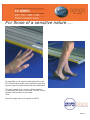
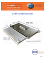
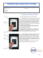
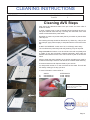
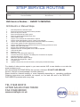
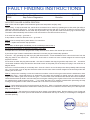
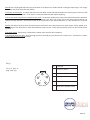
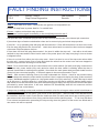
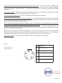
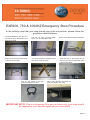
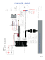
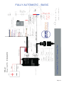
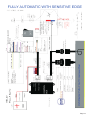
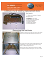
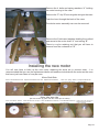
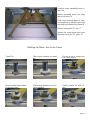
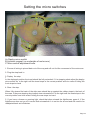
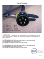
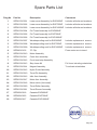
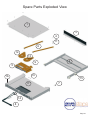
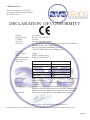
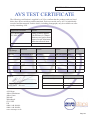
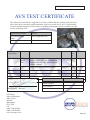
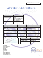
Owners Manual
EXE600HZ
EXE750HZ
EXE1000HZ
AVS Marketing Ltd,
Alders Farmhouse,
Alders Lane,
Whixall, Whitchurch,
Shropshire. SY13 2PZ
Tel
01948 880010
Fax 01948 880020
Email [email protected]
Web www.avssteps.co.uk
Contents
1.
2.
3.
4.
5.
6.
7.
8.
9.
10
11.
12.
13.
14.
15.
16.
17.
18.
19.
20.
21.
22.
23.
24.
25.
26.
About Your Step
Sensitive Edge Option
Step dimensions
Operating instructions
Cleaning Instructions
Step Service Routine
Fault Finding (deployed step)
Fault Finding (deployed step)
Fault Finding (stowed step)
Fault Finding (stowed step)
Emergency Stow Procedure
Wiring diagram Failsafe basic
Wiring diagram Fully Automatic
Wiring diagram Fully Automatic Sensitive Edge
Replacing motor
Installing new motor
Refitting motor arm
Setting micro switches
Fault finding - step motor
Spare Parts List
Exploded Diagram - Parts list
Declaration of conformity
AVS Benchmark test - Weight applied
AVS Benchmark test - Dirt compaction
AVS Benchmark test - Repeat cycles
For your notes
About your step
DESCRIPTION
Electrically operated slide in-slide out cassette step providing safe access to passenger vehicles by halving entrance
step heights
Quiet, powerful, smooth easy action
Operated by the driver/attendant or automatically on the door. (See options)
Closes automatically when door closes for safety
Step will stop if it encounters an object (See special option)
Control boxes fitted with thermal cut-out to prevent motor damage
Rubber buffers for “soft-landing” at end of travel
Magnetic reed switches control stow and deploy
Step platform is 600, 750 & 1000mm x 300mm 12” deep
2mm Galvanised steel case
Weather proof protection strip at front of step cassette
Self cleaning side arm action
Emergency stow facility and retention
Anodised aluminium tread assembly
Stainless steel runners with nylon rollers
12v electric motor.
Twin arm drive delivering evenly spread force to the step tread
Maintenance should be every year depending on use
To maintain: clean and lubricate with silicone spray every 30 days or as required.
Wiring loom consists of a loom to the dash from control box, loom to the step from control box (body loom), control
box with water proof plugs to step. Dash mounted switch, bezel and red flashing warning light. Zero battery drain
when stowed..
THE MOTOR UNIT
The “H” type motor designed specifically for AVS to AVS’s specification.
Tested to an equivalent of 20 years operation!
Operates at just 2amp and peaks at 10amps.
Tested to 10 hours at full amps against a solid obstruction.
Installed in the T Type step as a single arm.
Installed in the EX Type step with a twin arm mechanism.
TECHNICAL
Voltage 12V
Current Approx. 2 amps during deploy and stow.
Deploy time: 3 seconds
Stow time: 3 seconds
Tread width 600,750 & 1000mm
Tread depth 300mm 12”
Deploy reach: 250mm 10”
Tested to: 250Kg 550Lbs
SWL: 150 Kg 300Lbs
Weight: 26Kg 57lbs (600mm step only)
TYPICAL USES:
Sliding side door entrances
Minibuses Ambulances
Utility vehicles School buses
OPTIONS:
Widths: 600, 750, 1000mm
Fully auto operation - simply swap the control
box and switch to change to fully automatic operation on the door. This is a no cost
option when ordered with the step.
CERTIFICATION
Cycle test
Dirt Ingress Test
Dirt Compaction Test
EMC Test
INSTALLATION
Easily mounts to the vehicle cill or step box section support
at front and to chassis member at rear. Full fitting instructions
and wiring
plans. On line assistance if required.
Fitting kit options include Mercedes Sprinter, VW LT and
Crafter, Freightliner and Dodge Sprinter
Universal kits will fit most other vehicles
Unique serial number making all AVS step fully traceable
Individual service pack and maintenance record
SPECIAL OPTIONS:
Touch sensitive edge - stops power to motor on encountering
any obstruction
Automatic operation on the door
Page 1
For those of a sensitive nature.....
As specified on all steps for Mercedes Benz, the
EX is fitted with a bright yellow sensitive edge that
stop the step if it make contact with any obstruction
The step operation is reset by simply pressing
or releasing the switch in the cab. The EX is very
reliable and sensitive at the same
Time.
Sensitive edge strip is an option on all EX
Page 2
STEP DIMENSIONS
EXE600 - 690mm
EXE750 - 840mm
EXE1000 - 1090mm
472mm
170mm
300mm
330mm
40mm
66mm
EXE600 - 600mm
EXE750 - 750mm
EXE1000 - 1000mm
Model Shown EXE1000HZSE
Page 3
OPERATING INSTRUCTIONS
STEP TYPE
VEHICLE TYPE
SIDE
ENTRANCE
COUNTRY
AVS Electric steps
Last Updated
Revision no:
09/07/06
0
Operating AVS Electric Steps
In
Rocker
switch
There are 2 main types of electric step operation.
1.
FAIL SAFE - The step opens (deploys) and closes
(Stows) using a rocker switch usually mounted near the
driver with an AVS aluminium coloured bezel. Sometimes
there is a switch near the door and sometime in both
places. By pressing the switch one way the step will
deploy and a red light will flash on the dash board. By
pressing the switch the other way the step will retract and
the red light will stop flashing.
The step will stop automatically at either end of travel.
If the step is deployed it will stow automatically when:
A) The side door is closed OR
B) The hand brake s released.
In other words the step will make its self SAFE if the
driver FAILS to stow the step. Whether it is side door or
hand brake operated depends on the way the coach
builder has connected the AVS wiring harness.
Out
OFF
On/Off
switch
2.
FULLY AUTO - The step opens and closes as the
nearest door is opened and closed. The step can be
switched of in the deployed or stowed position by using
the on/off switch usually mounted on the dash board. By
switching the step off it will not stow or deploy when the
door is opened and closed. The red warning light will
continue to flash if the step is not stowed even if the on/off
switch if in the off position.
(You may wish to isolated the step in the open position
with the door closed to allow it to be cleaned.
ON
Page 4
CLEANING INSTRUCTIONS
STEP TYPES
All
Last Updated
Version:
09/07/06
2
Cleaning AVS Steps
Steps should be cleaned at least once per month and more often if
conditions dictate.
By using a power hose or even a standard hose frequently ensure no
build up of material inside the step. The step will “self-clean” if the mud
and dirt is lubricated with a power wash.
Remember to clean not just the tread (the bit you stand on) but the side
of the step too.
After cleaning the step should be allowed to dry. When dry, a day or two
later perhaps, apply silicone spray to help lubricate the movement of the
step.
DO NOT USE GREASE. Avoid use of oil, it will simply wash away.
If the conditions are particularly bad daily cleaning may be required.
Every 6 months the bottom cover should be removed completely and
the inside of the step physically cleaned particularly either side the
stainless steel tubular runners. This can be done as part of the service
routine.
Failure to clean the steps regularly or to service the steps may result in
the failure of the step in service. This will not be covered under warranty.
We recommend that mud flaps are fitted to your vehicle.
Your step serial number is on the front RHS of the tread. This will tell
AVS exactly what type of step you have.
For more information contact AVS on:
Tel
Fax
SALES:
01948 880010
01948 880020
AFTERSALES
01948 780238
01948 780458
Silicone Spray is supplied by
Rocol on 0113 232 2700
www.rocol.com
Applying Silicone Spray after the step has dried.
Page 5
STEP SERVICE ROUTINE
STEP TYPE
TITLE
All AVS steps
Service Routine
Last Updated
Revision no:
19/6/06
1
AVS Service Routine - EVERY 12 MONTHS
AVS Electric or Manual Steps.
1.
2.
3.
4.
5.
6.
7.
8.
9.
10.
11.
12.
13.
14.
14.
15.
16.
17.
18.
19
20.
21.
22.
Note step serial no and start report
Disconnect electrical connections where possible
Remove step from vehicle
Remove tread plate and lower panel
Remove guide rods(Cassette steps only)
Clean inside of case
Inspect micro switches and clean/lube or replace
Inspect tread plate linkage to motor. Check nylon bearings.
Inspect and clean/replace stainless steel tubes and rollers as necessary
Check nylon guides for wear. Replace as necessary
Inspect connections to micro switches and motor including grommets in case
Inspect and clean tread plate.
Supply and fit weatherproofing kit if not fitted
Replace side arm mounting bolts and Loctite as required.
Lubricate all parts.
Replace cover
Refit step. Leave fitting hand tight only.
Connect electrics as required. Use waterproof connections is required
Operate step approx. 10 times
Refit lower panel and tighten fittings
Test again and weight test. 150Kg
Compile report.
Update customer Service Record book (In blue pack provided with Step)
For details of other service agents in your area contact AVS or see details on our web site
www.avssteps.co.uk.
We recommend SILICONE SPRAY be used as a lubricant. DO NOT USE GREASE.
Service interval is recommended 6 months maximum.
Steps should be cleaned monthly or more frequently depending on operating conditions.
Cleaning instructions are available on request, on our web site and in the SERVICE
DOCUMENTS provided with every step.
TEL 01948 880010
AFTER SALES 01948 780238
FAX 01948 880020
www.avssteps.co.uk
Page 6
FAULT FINDING INSTRUCTIONS
STEP TYPE
TITLE
Electric T and E
Step Failure Diagnostics
Last Updated
Revision
25/06/07
1
AVS STEP FAILURE IN OPEN POSITION
Test 1: With side door open / hand brake on/ ignition on/ step switch on (fully auto):
Listen closely to step underneath the vehicle when someone tries to close it by operating the rocker switch (fail safe) or
closing the side door (fully auto). (For fully auto steps make sure the side door is open for at least five minutes first to
allow the motor thermal switch to cool if the step is jammed in any way and the motor has been trying to close the step.
The switch will automatically switch off the motor and needs to cool before it will reconnect.)
If no noise from the step – go to test 2
If step makes a noise but does not move – go to test 3
Test 2: Check 10 amp fuse in power lead to / in control box.
If blown - replace and recheck step operation.
If fuse does not blow again immediately or has not failed proceed to test 4:
If fuse blows immediately on attempted operation of the step:
Pull apart the loom connection plug at back of step unit and check state of the internal pin connectors.
If pins show signs of water contamination clean and re-connect plug and retest step operation.
If pins OK - retry operating step with 5 pin plug still disconnected – if fuse still blows there is a short in the loom from the
step plug back to the control box - check loom wires back to control box have not been trapped or become frayed
anywhere obvious.
If fuse does not blow with plug disconnected – the short is between the step plug and the step motor unit. - test with a
circuit tester earthed to step case and the other lead to each of the power pins in the step loom plug in turn as shown in
diagram below:
If there is a circuit from either pin to the step case – there is a short in one of the step motor wires probably within the step
unit – remove lower cover of step and check the wires from the motor have not been trapped or become frayed and are
shorting out on the case.
Test 3: If step motor is making a noise and continues to make a noise for as long as rocker switch is held down or door
closed (fully auto) – check that there is no obstruction in the step unit preventing it closing such as a piece of gravel
trapped in the slides / gear mesh of twin arm types. – remove lower cover and disconnect the link arm/s from the tread.
Check that the tread can slide in and out easily and check gear meshing point of gear arms on twin arm units are free of
any particles that could be jamming them. - If it is clear that there is no external contamination preventing the step
moving then the gearbox of the motor has failed and a new motor unit will be required.
Test 4: Unplug step from body loom at plug at rear of step unit. With a circuit tester and step unit still deployed, check
that there is no circuit between the stowed micro-switch pin and the micro-switches common return pin in the step loom
plug. (see diag below).
If there is a circuit – the stowed micro-switch has stuck closed or has failed closed. Remove bottom cover of step and
check the stowed micro-switch (the one that would be activated when the step is closed ) is not damaged, if damaged it
will need replacing
Page 7
Test 5: At the unplugged step loom plug at the back of the step unit or inside vehicle on BA type steps apply a 12v supply
across the two power pins (see diag below).
If the step remains dead - it is likely that the motor has failed. Check first that the leads from the plug to the motor are OK
particularly within the step unit – if OK then the motor has failed and will require replacing.
If the motor starts to buzz but the step does not move – reverse the polarity across the power pins and see if the step then
closes. If the step can be deployed and stowed by applying the direct 12v supply across the power pins (reversing it to
change the step direction) – the fault lies either in the control unit, rocker switch (fail safe), or in the vehicle loom. Go to test
6.
Test 6: (Fail safe only) First check the wire terminal connections of the blue wires to the rocker switch. If they appear to be
OK, unplug the two blue wires or blue and blue/white wires from the rocker switch and with a piece of wire connect them
together.
If the step closes - then there is a fault with the switch and it will have to be replaced.
If the step still does not close - Do a thorough check on the multi-plug connectors to the control unit – if these are in order it
is likely that the control unit has failed.
Diag 1
No Function
View of pins in
plug from step
1
5
4
2
3
1
Power to motor
2
Stow m/switch
3
Deploy m/switch
4
Power to motor
5
M/switch common return
Page 8
FAULT FINDING INSTRUCTIONS
STEP TYPE
TITLE
Electric T and E
Step Failure Diagnostics
Last Updated
Revision
25/06/07
1
STEP FAILURE IN STOWED POSITION
Test 1: With side door open / hand brake on/ ignition on/ step switch on:
Check 10 amp fuse in power lead to / in control box.
If blown - replace and recheck step operation.
If fuse does not blow again immediately or has not failed proceed to test 2:
If fuse blows immediately on attempted operation of the step:
Pull apart the loom connection plug at back of step unit and check state of the internal pin connectors.
If pins show signs of water contamination clean and re-connect plug and retest step operation.
If pins OK - re try operating step with plug still disconnected - if fuse still blows there is a short in the loom
from the step plug back to the control box - check loom wires back to control box have not been trapped
or become frayed anywhere obvious.
If fuse does not blow with plug disconnected - the short is within the step unit. - test with a circuit tester
earthed to step case and the other lead to each of the power pins in the step loom plug in turn as shown
in diagram below:
If there is a circuit from either pin to the step case - there is a short in one of the step motor wires within
the step unit - remove lower cover of step and check the wires from the motor have not been trapped or
become frayed and are shorting out on the case.
Test 2: Do a visual check on all wire connections to the rocker switch, (fail safe) multi plug connectors to
the control unit, power switch (fully auto) and also check the door switch is earthing when the door is
opened / hand brake is earthing when applied. Also check the main power lead and earth leads from the
control unit are connected properly. If these all appear to be correct proceed to Test 3.
Test 3: With someone listening close to the step underneath the vehicle - check for any sound coming
from the step motor when the rocker switch is pressed / door is opened to deploy the step. (make sure door
is open / handbrake applied / ignition on / step power switch is on (fully auto only) . (Note if the step is wired
up as fully auto 1- close the door for 1 mins before carrying out this test to allow the thermal switch on the
step motor to cool and reconnect if the motor has been trying to deploy the step for some time but has been
prevented by some obstruction. It will have switched off automatically and will not reconnect until the
thermal switch has cooled down.)
If step motor is making a noise and continues to make a noise for as long as rocker switch is held down or
door open (fully auto) - check that there is no obstruction in the step unit preventing it deploying such as a
piece of gravel trapped in the slides / gear mesh of twin arm types. - remove lower cover and disconnect
the link arm/s from the tread. Check that the tread can slide out easily and check gear meshing point of
gear arms on twin arm units are free of any particles that could be jamming them. - If it is clear that there
is no external contamination preventing the step moving then the gearbox of the motor has failed and a
new motor unit will be required.
Page 9
If step motor starts then cuts out with a small movement of the tread - Check that the door / handbrake lead
is connected properly to the switches and these are earthing when the door is open / handbrake applied.
(make sure ignition is also switched on). - If these are correct then the control unit is faulty and will need
replacing.
If step motor is silent - unplug the step loom plug at the rear of the step unit and apply a separate 12v supply
across the two power pins in the step loom plug (see diag below).
If the step motor remains silent - the motor has failed and will have to be replaced.
If step motor makes a noise but the step does not move - reverse the polarity and check that the step deploys.
If the step does not deploy but the motor still makes a noise go back to stage above to check for objects that
may be trapped in the step mechanism above.
If step can be deployed and stowed by applying a direct 12v supply to the step power pins but ceases to
operate when the plug is reconnected and operated by normal methods - deploy step using the direst power
supply to the pins then reconnect the plug and see if the step will close. - If the step will close but does not
deploy - the deployed micro-switch may have failed. (this is the micro switch that is activated by the motor
arm when the step is fully deployed).
With the step in any position other than fully deployed - use a circuit tester and check for a circuit across the
deployed microswitch pin and common return pin - see diag below. If there is a circuit - the micro-switch is
operating correctly and there is a fault in the step control box. This will have to be replaced.
If there is no circuit - the deployed micro-switch has failed and will have to be replaced.
Diag 1
No Function
View of pins in
plug from step
1
5
4
2
3
1
Power to motor
2
Stow m/switch
3
Deploy m/switch
4
Power to motor
5
M/switch common return
Page 10
EXE600, 750 & 1000HZ Emergency Stow Procedure
In the unlikely event that your step should stop in the out position, please follow the
procedure detailed below
On the underside of the step, you
will find 2 arms attached to the
aluminium tread
Pull the “R” clips out and retain
them, you will need them later.
Remove the arms and fold them
in and under the step
The arms need to be crossed over to
fully stow inside the case
The “R” clip needs to be fully
pushed through the holes
Remove the steel and nylon washers
Push the step in and insert the “R”
clip into the holes in underside of the
case on both sides
When fully through the holes the
pins will holds in the tread
IMPORTANT NOTE: This is a temporary fix to get you home only, your step should
be repaired by your nearest agent as soon as possible.
Page 11
FAILSAFE - BASIC
Page 12
FULLY AUTOMATIC - BASIC
Page 13
FULLY AUTOMATIC WITH SENSITIVE EDGE
Page 14
EXE600, 750 & 1000HZ Replacement Motor
Parts Supplied
1 x Motor unit inclusive of sensors
and plug in loom
1 x M8 Nyloc
1 x M8x25 Bolt (slave side)
1 x M8x15 Bolt (into motorshaft)
2 x M8 x24 steel washers
1 x M8 Spring washer
1 x M8x40 Nylon Washer
1 x M8 x25 Nylon Bush
Removing the old Motor
Unplug the step from the rear and remove the bottom
cover from the step to gain access to the motor unit.
Remove these bolts and slide
back 10mm to take of bottom
cover
Put a mark across the junction of the toothed arms (as
indicated by “A”) as this will save time later in lining
them up when putting them back.
A
B
Remove “R” clips “B” securing the arms to the treadand push the tread forward to give more room to work
B
Page 15
Remove the 4 bolts and spring washers “A” holding
the motor housing to the case
B
Remove the “P” clip “B” securing the wiring to the case
A
A
Push the loom through the back of the case.
The whole motor assembly can now be removed
A
A
Remove the 2 bolts and washers holding the toothed
gear arms to the motor shaft “A” and casing “B”.
A
B
There is a nyloc retaining nut that you will have to
remove from the underside of “B” .
Installing the new motor
You will now have to build up the new motor replacing the arms etc in reverse order - it is
recommended that you use the replacement bolts and washers included with the motor as the ones
that have just been taken of may be worn.
Motor Shaft Side
Start on the left with the bare
motor shaft
Replace the toothed motor arm Replace the M8 washer
Place the spring washer Finally the M8x15 bolt
on top of the M8 washer
using threadloc
Motor Idler arm side
(Be sure to line up gears with the marks put on earlier)
Place the M8x40 washer
over the hole in the bracket
Place the idler arm on top of Place the M8 bush inside the
the washer
hole
Place M8 steel washer on Tighten down bolt, take back a
quarter turn and sucure with
top of the bush
nyloc on the back
Page 16
Position motor assembly back in
the case
C B
A
Screw assembly back into step
with the 4 bolts “A”
A
A
Push loom through back of step,
not forgetting to replace grommet
securely in the back of the case “B”
A
Secure wiring with “P” clip “C”
Secure the motor arms back onto
the tread using the “R” clips “D”
D
D
Refitting the Motor Arm to the Tread
Tread Pin
Place nylon washer on tread
pin
Put arm on top of washer,arm
has a bush built in.
1
2
3
Place another nylon washer on top of arm
Place steel washer on top of
nylon washer
Finally secure all with “R”
clip
4
5
6
Page 17
Setting the micro switches
A1
C
B
C
A2
A1 Stow micro switch
A2 Deploy micro switch
B Actuator magnet (on underside of motor arm)
C Micro switch adjustment bolts.
1. Ensure all wiring is pinned back out of the way and will not foul the movement of the motor arm
2. Plug the step back in.
3. Deploy the step.
I
In the deployed position the tread should be fully extended, if it is stopping short adjust the deploy
micro switch A2 to the right until the tread stops in the correct position and vice versa if hitting the
front stops too hard
4. Stow the step.
When fully stowed the back of the side arms should be up against the rubber stops in the back of
the case, if they are stopping short adjust stow microswitch A1 to the right until the tread stops in the
correct position and vice versa if hitting the rear stops too hard.
5. If you have a buzzer or warning light, check that when stowed the light/buzzer goes of. If the
llight/buzzer does not go off it means that microswitch A1 is set too far around and will need to be
readjusted back anti clockwise.
Page 18
Fault Finding
View of plug leading from the
rear of the step, flat on plug in
the top position
1
2
5
4
3
1. Power +/(Black)
2. Stow m/s
(Blue)
3. Deploy m/s
(Purple)
4. Power -/+
(White)
5. Common to both m/s (Red)
Testing the Motor
To test if your motor is working or not, you can apply a direct 12v current to pins 1 and 4 and reverse to make the motor go the other way - but be careful as the motor will only stop when you
remove the current.
Testing the Stow micro switch
With the step stowed, use a circuit tester on pins 2 and 5, you will not get continuity
With the step deployed you will get continuity
With the step in the half way out position you will get continuity
Testing the Deploy micro switch
With the step stowed, use a circuit tester on pins 3 and 5, you should get continuity
With the step deployed you will not get continuity
With the step in the half way out position you will get continuity
Page 19
Spare Parts List
Diag No
Part No
Description
Comments
1
SPEX12010001
Lower cover Assembly for EXE600HZ
Includes all bolts and washers
1
SPEX12010002
Lower cover Assembly for EXE750HZ
Includes all bolts and washers
1
SPEX12010003
Lower cover Assembly for EXE1000HZ Includes all bolts and washers
2
SPEX12010004
Full Tread Assembly for EXE600HZ
2
SPEX12010005
Full Tread Assembly for EXE750HZ
2
SPEX12010006
Full Tread Assembly for EXE1000HZ
3
SPEX12010007
Weatherproofing seal for EXE600HZ
Includes replacement screws
3
SPEX12010008
Weatherproofing seal for EXE750HZ
Includes replacement screws
3
SPEX12010009
Weatherproofing seal for EXE1000HZ
Includes replacement screws
4
SPEX4010126
“R” Clip
Fixes motor arm to tread
5
SPEX12010010
Motor Assembly
6
SPEX12010011
Crank Arm assembly
7
SPEX12010012
Front tread stop Assembly
8
SPEX12010013
Step Loom Kit
Full loom including m/switches
9
SPEX12010014
Magnet Assembly
To activate m/switches
10
SPEX12010015
Nylon Guide Assembly
11
SPEX12010019
Tread Pin Assembly
12
SPEX12010016
Idler Arm Assembly
13
SPEX12010017
Motor Arm Assembly
14
SPEX12010018
Micro switch (Universal)
15
SPEX12010020
Tread Roller Assembly
16
SPEX12010021
Tread Runner Assembly
17
SPEX8010218
Cassette EXE600HZ
18
SPEX8010223
Cassette EXE750HZ
19
SPEX8010217
Cassette EXE1000HZ
Page 20
Spare Parts Exploded View
1
3
4
11
6
12
13
2
9
5
10
16
15
17
7
14
8
Page 21
CERTIFICATION
This is to certify that AVS Steps
have met the following specification
and EU Directives
DECLARATION OF CONFORMITY
Product:
Product Codes:
CE Mark:
Serial No:
Directives:
Legal load
Requirement:
SWL:
Tested Maximum:
Specification of
Materials:
Recycling:
Cycle Test:
Decals:
Declaration:
AVS Steps.
EE, EX, G, LX, K, SL, T.
All steps.
All steps. Identifies product.
All AVS Steps are manufactured to the relevant EU directives.
2001/85/EC Bus and Coach Directive
98/37/EC Mechanical Handling Directive
72/245/EC Radio Interference Suppression
136Kg
150Kg x 50,000 cycles
225Kg x 25,000 cycles
Step Material
Data
Aluminium
6063-T6 AA15
Nylon
Nylon 66
Fixing grade
8.8 & stainless steel
Steel case
Galvanised
Steel internal
Stainless
Materials listed will require separating prior to recycling under
current legislation.
Minimum cycle test is 100,000 operations under a load of
2.5Kg force.
All steps have operation labels applied
Additional label for application to the vehicle for maintenance
Additional label for application to vehicle for foot operation
We hear by certify the above information to be correct.
Mr K Clarke - Director/Representative for AVS
AVS Marketing Ltd Company Registration No 3973828 Registered in UK. Directors Karen Clarke Keith Clarke
Page 22
CERTIFICATE No: 13/19/04/2007
AVS TEST CERTIFICATE
The following certification is supplied by AVS to confirm that the products and test listed
below have been carried out and documented. Each test carried out by AVS is individually
recorded and documented. Further details, including photographs, may be available on some
test by contacting AVS.
Applicable Standard
Details
AVS Bench Mark
EU 2001/85/EC
250Kg (550lbs) applied
100,000 times to 100mm
diameter steel pad at front
centre of tread. Maximum
deflection allowed 8mm.
Step
Type/Range
Standard
Details
Result
EXE600
AVS Bench Mark
As above
240,000 cycles Pass
Signed:
Summa- Date
ry
Test Carried By:
Date
Shaun Connolly
19th April 2007
19/04/07
Keith Clarke - Director
AVS Steps
Alders Farmhouse
Alders Lane
Whixall
Whitchurch
SY13 2PZ
UK
0044 1948 880010
0044 1948 880020
www.avssteps.co.uk
Page 23
CERTIFICATE No: 21/12/11/2006
AVS TEST CERTIFICATE
The following certification is supplied by AVS to confirm that the products and test listed
below have been carried out and documented. Each test carried out by AVS is individually
recorded and documented. Further details, including photographs, may be available on some
test by contacting AVS.
Applicable Standard
Details
AVS Bench Mark
None
Dirt Compaction Test
Step
Type/Range
Standard
Details
Result
Sum Date
ma
ry
EXE1000HZ
AVS
Bench
Mark
20Kg of mud (clay based) compacted into
the step artificially. Mud compacted
around motor and side arms in stowed
position. Operate.
Operates
Pass 21/12/06
Repeat from open position. Operate.
Operates
Pass 21/12/06
Continue Operation
10 cycles
Pass 21/12/06
Signed:
Test Carried By:
Date
Mr KM Higgins
Chief Engineer
21st December 2006
Test Number
27
Keith Clarke - Director
AVS Steps
Alders Farmhouse
Alders Lane
Whixall
Whitchurch
SY13 2PZ
UK
0044 1948 880010
0044 1948 880020
www.avssteps.co.uk
Page 24
CERTIFICATE No: 30/01/10/2007
AVS TEST CERTIFICATE
The following certification is supplied by AVS to confirm that the products and test listed
below have been carried out and documented. Each test carried out by AVS is individually
recorded and documented. Further details, including photographs, may be available on some
test by contacting AVS.
Applicable Standard
Details
AVS Bench Mark
No standard applies
Bench mark is 100,000
cycles.
Cycle Test against a 2.5N
force restricting both
stow and deploy
NOTE:
Interim certificate. Test is
continuing
Step
Type/Range
Standard
Details
Result
Summa- Date
ry
“H” type
Motor. Twin
arm.
AVS Bench Mark
As above
115,320
Cycles to date
Pass
Signed:
30/1/07
Test Carried By:
Date
AVS Test Rig
Mr Shaun Connolly
From 19th Dec 2006 to
2nd Jan 2007
Test Number
25
Keith Clarke - Director
AVS Steps
Alders Farmhouse
Alders Lane
Whixall
Whitchurch
SY13 2PZ
UK
0044 1948 880010
0044 1948 880020
www.avssteps.co.uk
Page 25
Useful Information to Keep
Step Serial No
Model
Nearest Service
Agent
Next Service Due
Other details
Page 26