1
V. 1.2, 22.04.2013, RB
ITV-GECWV407M User Manual
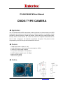
CMOS TYPE CAMERA
Application
The ITV-GECWV407M JPEG compression module performs as a video camera or a JPEG
compressed still camera and can be fixed into all kinds of system. For example: remote
monitoring, vehicle monitoring, visible the doorbell, camera phones, digital image records,
industry control, access control, etc. Users can send out a snapshot command from the
host in order to capture a full resolution single-frame still picture. The picture is then
compressed by the JPEG engine and transferred to the host.
Feature
1. Small size: 28mm x 20mm (L x W).
2. 0.3M CMOS ensor, VGA resolution, down sample to QVGA.
3. Video-out: VGA & 60fps, optional.
4. Low power consumption, 3.3V operation.
5. UART interface support up to 115.2Kbps.
6. Built-in JPEG CODE.
7. Built-in lens, optional.
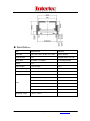
Outline
5.15
© 2013 Intertec Components GmbH, Erdinger Str. 45, 85356 Freising. www.intertec.org
1
Block Diagram
Board Layout
Pin Function
*The default socket is 4 pins, we will not assemble the fifth pin (Video out) unless user specify.
1.Lens Structure
© 2013 Intertec Components GmbH, Erdinger Str. 45, 85356 Freising. www.intertec.org
2
Specification
Item
Specification
Remark
Pixel Size
PAL:628 x 582 / NTSC:510 x 492
NTSC default
Image Sensor
1/5”
CMOS sensor OV7740
Baud Rate
9.6Kbps~115.2Kbps
115.2Kbps default
Output
TTL
Video Output
VGA & 60fps
Operating Voltage
3.3V±10%
Working Current
110 mA
1Vp-p
Construction: 4P+IR filter
Effective Focal Length:3.27mm
F#:2.5
Lens
FOV:58°
Distortion <1.0%
Relative illumination: 60% Ø3.44
Operating Temp.
-20°C~+60°C
© 2013 Intertec Components GmbH, Erdinger Str. 45, 85356 Freising. www.intertec.org
3
User Manual
1. Serial Interface
1.1 Baud Rate
The ITV-GECWV407M supports total 5 types of baud rate: 9,600bps, 19,200bps,
38,400bps, 57,600bps and 115,200bps. Default baud rate is 115,200bps. In other words,
host needs to use 115200bps at the first connection with ITV-GECWV407M. After the first
connection, host can change the baud rate to other supported values.
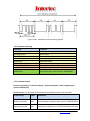
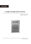
1.2 Single Byte Timing Diagram
A single byte RS-232 transmission consists of one start bit, 8-bit contents and one stop bit.
A start bit is always 0, while a stop bit is always 1. LSB is sent out first and is right after the
start bit.
Figure 5 RS232 communications – single byte timing diagram
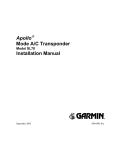
1.3 Command Timing Diagram
A single command consists of 4 or more (depends on data length’s value) continuous
single byte RS-232 transmissions. The following is an example of GET VERSION (56h,
00h, 11h, 00h) command.
© 2013 Intertec Components GmbH, Erdinger Str. 45, 85356 Freising. www.intertec.org
4
Figure 6 GET VERSION command timing diagram
1.4 Command summary
Command
Functions
GET VERSION
Get Firmware version information
SYSTEM RESET
System reset
FBUF CTRL
Control frame buffer
GET FBUF LEN
Get image lengths in frame buffer
READ FBUF
Read frame buffer
SET BAUDRATE
Set serial baud rate
SET SAMPLESIZE
Set image size(VGA/QVGA)
SET COMPRESSRATIO
Set image compressed rate
COM REPLY
Host will get reply command from JC409M-W01
Table 1 command summary
1.5 Command format
Protocol sign(1byte) + Serial No.(1byte) + Command(1byte) + Data length(1byte) +
Control data(nbytes)
Protocol sign: This one byte field indicates the transmitting mode of the command.
Protocol sign
value
definitions
Sending command
56h
The command is sent from the host to ITV-GECWV407M
Replying command
76h
Command is received from ITV-GECWV407M to the host
© 2013 Intertec Components GmbH, Erdinger Str. 45, 85356 Freising. www.intertec.org
5
Table 2 protocol sign
Serial No.: Now this one byte field is invariably set to 0.
Command: This one byte filed indicates the command function. About the detail, please
refer to Table 3 command set.
Data length: This one byte field specifies the total length in bytes of control data by which
is followed.
Control data: The data of this field is only meaningful when Data length is not equal to 0.
This data depends on the different commands. About the details, please refer to the
following sections.
1.6 Command protocol
Command name
Protocol
sign
Serial No.
Command Data
value
length
Control data
GET VERSION
56h
00h
11h
00h
Don’t care
SYSTEM RESET
56h
00h
26h
00h
Don’t care
FBUF CTRL
56h
00h
36h
01h
To know data vaule of this
GET FBUF LEN
56h
00h
34h
01h
field, please refer to the
READ FBUF
56h
00h
32h
0Ch
following sections
SET BAUDRATE
56h
00h
31h
06h
SET SAMPLESIZE 56h
00h
31h
05h
SET
56h
COMPRESSRATIO
00h
31h
05h
To know data vaule of this
field, please refer to the
following sections
Depends on the different sending commands. To
COM REPLY
76h
00h
know data value of this field, please refer to the
following sections
Table 3 Command set
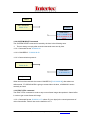
1.6.1 GET VERSION Command
The GET VERSION command is used to get version information of the firmware running in
ITV-GECWV407M.
1.6.1.1 Command format: 56 00 11 00
1.6.1.2 COM REPLY: 76 00 11 00 0B 56 43 30 37 30 36 20 31 2E 30 30 ("VC0706 1.00")
6.6.1.3 Communication protocol:
To get the firmware version, please follow the below operations:
© 2013 Intertec Components GmbH, Erdinger Str. 45, 85356 Freising. www.intertec.org
6
HOST
GET VERSION
56 00 11 00
MODULE
COM REPLY
76 00 11 00 0B 56 43
30 37 30 36 20 31 2E
30 30
1.6.2 SYSTEM RESET Command
The SYSTEM RESET command is issued by the host in the following case:
There is always no reply after several commands were sent by host.
1.6.2.1 Command format: 56 00 26 00
1.6.2.2 COM REPLY: 76 00 26 00 00
1.6.2.3 Communication protocol:
SYSTEM RESET
56 00 26 00
COM REPLY
76 00 26 00 00
Delay 2000ms
When the host has received the correct COM REPLY [76 00 26 00 00], after about ten
milliseconds, ITV-GECWV407M is going to restart. About 2s later, JC409M-W01 works
normally as usual.
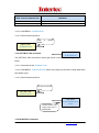
1.6.3 FBUF CTRL command
The FBUF CTRL command is used to stop current frame image data update in frame buffer
in order to get current frame still image.
1.6.3.1 Command format: 56 00 36 01 P1 where P1 (one byte) is the control parameter of
video frame buffer. Table 4 lists out the definition of P1.
© 2013 Intertec Components GmbH, Erdinger Str. 45, 85356 Freising. www.intertec.org
7
Frame control parameter (P1)
Definition
0
Stop frame buffer data update at current frame
3
Resume normal video state
Table 4 Frame control parameter
1.6.3.2 COM REPLY: 76 00 36 00 00
1.6.3.3 Communication protocol:
Stop at
frame
current
FBUF CTRL
56 00 36 01 00
COM REPLY
76 00 36 00 00
1.6.4 GET FBUF LEN command
The GET FBUF LEN command is used to get size of current frame still image in frame
buffer.
1.6.4.1 Command format: 56 00 34 01 00
1.6.4.2 COM REPLY: 76 00 34 00 04 P2 where P2 (4 bytes) is the size of image data which
host wants to get.
1.6.4.3 Communication protocol:
Get size of current
frame
GET FBUF LEN
56 00 34 01 00
Current frame still
image data size is
00012C00h
COM REPLY
76 00 34 00 04 00 01
2C 00
1.6.5 READ FBUF command
© 2013 Intertec Components GmbH, Erdinger Str. 45, 85356 Freising. www.intertec.org
8
The host sends this command to get the image data from frame buffer.
1.6.5.1 Command format: 56 00 32 0C 00 0A 00 00 00 00 P3 P4 where P3 (4 bytes) informs
JC409M-W01 that how many bytes of data the host is going to read. It must be multiple of 4.
P4 (2 bytes) represents the delay time between the command and data received from COM
REPLY (see 6.6.5.2). The time unit is 0.01 millisecond. For example: P4 = 10 00, delay time
is 10 milliseconds.
1.6.5.2 COM REPLY: 76 00 32 00 00 P5 76 00 32 00 00 where P5 (n bytes) is the image
data which host wants to get. n is equal to P3 in this case.
1.6.5.3 Communication protocol:
READ FBUF
56 00 32 0C 00 0A 00
00 00 00 00 00 02 00
10 00
Get image from frame
buffer, data size 0200h,
delay time 1000*0.01=10ms
COM REPLY
76 00 32 00 00
Get image data
starting
command
Image data
Get image data,
size 0200h
COM REPLY
76 00 32 00 00
Get image data
ending
command
Note: Before sending this command, users should issue GET FBUF LEN command to
get the image size first.
© 2013 Intertec Components GmbH, Erdinger Str. 45, 85356 Freising. www.intertec.org
9
1.6.6 SET BAUDRATE command
The host issues this command to set the UART baud rate.
1.6.6.1 Command format: 56 00 31 06 04 02 00 08 P6 where P6 (2 bytes) is the
configuration value of UART baud rate. The relationship between configuration value and
baud rate is shown in Table 5.
Baud rate(bps)
Configuration value
9600
0xAEC8
19200
0x56E4
38400
0x2AF2
57600
0x1C4C
115200
0x0DA6 (default)
Table 5 Baud rate relationship
1.6.6.2 COM REPLY: 76 00 31 00 00
1.6.6.3 Communication protocol:
Set baud rate to
38400bps
SET BAUDRATE
56 00 31 06 04 02
00 08 2A F2
COM REPLY
76 00 31 00 00
1.6.7 SET SAMPLESIZE command
The host issues this command to set the sample size of image (image resolution).
1.6.7.1 Command format: 56 00 31 05 04 01 00 19 P7 where P7 (1 byte) is the configuration
value of image sample size. The relationship between configuration value and image
resolution is shown in Table 6.
© 2013 Intertec Components GmbH, Erdinger Str. 45, 85356 Freising. www.intertec.org
10
Image resolution
Configuration value
VGA
0x00 (default)
QVGA
0x11
QQVGA
0x22
Table 6 image resolution size relationship
1.6.7.2 COM REPLY: 76 00 31 00 00
1.6.7.3 Communication protocol:
Set image size to
QVGA
SET SAMPLE SIZE
56 00 31 05 04 01
00 19 11
COM REPLY
76 00 31 00 00
1.6.8 SET COMPRESSRATIO command
The host issues this command to set compressing rate of the image.
1.6.8.1 Command format: 56 00 31 05 04 01 00 1A P8 where P8 (1 byte) is the
configuration value of image compression ratio. This compression ratio value is ranged from
0x00 to 0xFF. The bigger the value is, the higher the compression ratio. Default
compression ratio is 0x35.
1.6.8.2 COM REPLY: 76 00 31 00 00
1.6.8.3 Communication protocol:
SET COMPRESSION RATIO
56 00 31 05 04 01 00 1A
50
Set image compression
ratio to 0x50
COM REPLY
76 00 31 00 00
© 2013 Intertec Components GmbH, Erdinger Str. 45, 85356 Freising. www.intertec.org
11
1.6.8 COM REPLY command
The COM REPLY is a UART command which is sent from ITV-GECWV407M in order to
inform the host whether the command which was just sent is executed well or in order to
transmit the data which the host wants to get. About all cases of COM REPLY command
please refer to the above commands sections.
NOTE: When the host issues SET BAUDRATE command, SET SAMPLE SIZE
command or SET COMPRESS RATIO command, the system needs to restart to take
effect. These parameters are stored into camera module’s built-in EEPROM. So next
time module boots up, these parameters still work.
© 2013 Intertec Components GmbH, Erdinger Str. 45, 85356 Freising. www.intertec.org
12
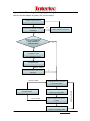
Appendix A – Flow diagram for getting an image
Below is the flow diagram for getting one or more images:
Camera module power up
Wait for 2000ms
Connect with camera module @
N
Camera module power down
115200bps
Y
Needs to change EEPROM
parameters (baud rate,
image resolution,
compress ratio)?
N
Y
Set BAUD RATE
Set SAMPLE SIZE
Set COMPRESS RATIO
Y
SYSTEM RESET
Wait for 1000ms
Connect camera module at new
Y
baud rate
Wait for 1000ms
Send FBUF CTRL command
to stop frame buffer
No for 3 times
ready to get image data
Get image data from camera
module
Get image data loop
Send GET PBUF command and be
SYSTEM RESET
Send FBUF CTRL command to
resume normal video state
© 2013 Intertec Components GmbH, Erdinger Str. 45, 85356 Freising. www.intertec.org
13
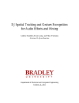
Appendix B: Communication example for getting an image
Below is the example for how to get a QVGA image by UART @ baud rate 57600bps and
higher compression ratio.
Set UART baud rate
57600bps
SET BAUD RATE
56 00 31 06 04 02 00 08
1C 4C
COM REPLY
76 00 31 00 00
Set image format size
to QVGA
SET SAMPLE SIZE
56 00 31 05 04 01 00 19
11
SET COMPRESSIONRATIO
56 00 31 05 04 01 00 1A
50
Set
image
compression ratio to
0x50
COM REPLY
76 00 31 00 00
COM REPLY
76 00 31 00 00
SYSTEM RESET
56 00 26 00
COM REPLY
76 00 26 00 00
Delay
2000ms
Stop at
frame
current
FBUF CTRL
56 00 36 01 00
COM REPLY
76 00 36 00 00
© 2013 Intertec Components GmbH, Erdinger Str. 45, 85356 Freising. www.intertec.org
14
Current
frame
size is 25D4 h
GET FBUF LEN
56 00 34 01 00
COM REPLY
76 00 34 00 04 00 00
25 D4
READ FBUF
56 00 32 0C 00 0A
00 00 00 00 00 00
25 D4 10 00
Image size is 0x012C00,
data delay time is 1000*01
= 10ms
COM REPLY
76 00 32 00 00
Get image data
starting
command
Image data
Get image data,
size 25D4h
COM REPLY
76 00 32 00 00
Get image data
ending
command
Resume
state
normal
video
FBUF CTRL
56 00 36 01 03
COM REPLY
76 00 36 00 00
© 2013 Intertec Components GmbH, Erdinger Str. 45, 85356 Freising. www.intertec.org
15
The image data we got from ITV-GECWV407M by performing the above operations is
indicated as below:
FF D8 FF FE 00 24 DA 0E 6C 96 00 00 00 00 00 00 00 00 00 00 00 00 00 00 00 F0 00 40
01 7F 00 32 12 0B 51 04 51 04 00 00 FF DB 00 84 00 20 16 18 1C 18 14 20 1C 1A 1C 24
22 20 26 30 4F 34 30 2C 2C 30 61 45 49 3A 4F 73 65 79 77 71 65 6F 6D 7F 8F B7 9B 7F
87 AD 89 6D 6F 9F D8 A1 AD BD C2 CC CE CC 7B 99 E0 F0 DE C6 EE B7 C8 CC C4 01
22 24 24 30 2A 30 5D 34 34 5D C4 83 6F 83 C4 C4 C4 C4 C4 C4 C4 C4 C4 C4 C4 C4 C4
C4 C4 C4 C4 C4 C4 C4 C4 C4 C4 C4 C4 C4 C4 C4 C4 C4 C4 C4 C4 C4 C4 C4 C4 C4 C4
C4 C4 C4 C4 C4 C4 C4 C4 C4 C4 C4 FF FE 00 05 00 00 00 FF C0 00 11 08 00 F0 01 40 03
01 21 00 02 11 01 03 11 01 FF C4 01 A2 00 00 01 05 01 01 01 01 01 01 00 00 00 00 00 00
00 00 01 02 03 04 05 06 07 08 09 0A 0B 01 00 03 01 01 01 01 01 01 01 01 01 00 00 00 00
00 00 01 02 03 04 05 06 07 08 09 0A 0B 10 00 02 01 03 03 02 04 03 05 05 04 04 00 00 01
7D 01 02 03 00 04 11 05 12 21 31 41 06 13 51 61 07 22 71 14 32 81 91 A1 08 23 42 B1
…………
6F C2 90 8C 99 10 C6 E5 1B A8 AB 76 77 38 22 39 0F 1F C2 69 8C BF 54 6E EC F2 4C 91
0E 7B AD 21 12 5A D9 88 B0 F2 61 9F B7 A0 AB 74 0C 28 A0 42 D1 40 10 5C CE 61 50 42
16 CF E5 51 5D 28 9E 01 2C 64 9C 73 8C FF 00 9E 68 00 CF DA ED 3D 64 5F E7 FF 00
D7 A4 83 FD 22 CD A2 FE 25 E9 FD 29 8C 48 0F 9D 65 24 7F C4 BD 07 EA 29 10 F9 9A
73 8F EE E7 FC 68 00 63 9D 34 7B 1C 7E B5 66 03 8B 64 3E 8B 48 07 02 A7 B5 41 7E D8
83 1E A4 50 22 39 FF 00 77 66 89 DC E2 96 5F DC 59 85 1C 33 53 01 50 0B 7B 6D C7 EF
1A 4B 44 2A 1A 57 3D 68 01 F0 DC 79 AE CB B7 81 D0 D4 F4 80 28 A0 04 A2 80 3F FF FF
FF FF D9
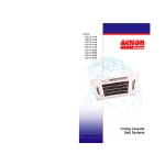
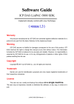
To verify the correctness of the image data, we can see the data starting at FF D8 and
ending at FF D9. It tells us that this is the correct image data. Then follows procedures
below, we can get an integral image:
1. create a file and name it as XXX.JPG
2. put the correct image data into it
3. save the file
Performs the above operation, the image is shown as below:
© 2013 Intertec Components GmbH, Erdinger Str. 45, 85356 Freising. www.intertec.org
16