1
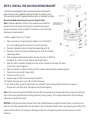
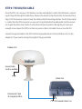
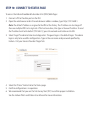
Land Station
Quick Start Guide
Version 1.0
Read Installation Guide, User Manual and all safety information before installing or
using Iridium Pilot Land Station. Failure to do so can result in serious injury or death.
The User Manual contains important warranty terms, limitations, exclusions and
terms and conditions that govern your use of Iridium Pilot Land Station. The User
Manual and Installation Guide are available at www.Iridium.com.
www.iridium.com
[email protected]
toll free: +1.866.947.4348
phone: +1.480.752.5155
INSTALLATION COMPONENTS & PARTS LIST:
1. Iridium Pilot Land Station Unit includes the following parts:
A.
B.
C.
D.
E.
F.
G.
H.
I.
Outdoor Unit (ODU)
Mounting bracket
Indoor Unit (IDU)
ODU/IDU cable (10 m included and 30 m cable available)
IDU power supply unit: the AC power supply unit (PSU) provides power to the IDU
Iridium Pilot Land Station accessory CD
SIM card
ODU Ground cable 3 m (8 m cable available)
IDU Ground Cable 2.5 m
A
H
C
B
E
D
I
F SIM card, reset button
and on/off switch are
located behind panel
Required Materials for Installation:
1. User supplied pole/mast/mounting location
2. Windows compatible computer
3. Ethernet cable (installer/customer provided)
4. RJ11 telephones
5. Slotted and Phillips screw drivers
6. Hammer and center punch
7. Power drill and associated bits
8. Wire cutters
9. Wire strippers and terminal lug crimper
10. RJ-45 crimp tool
11. Electrical tape
12. Anti-seize compound
13. Ground connection location
14. Electrical clips (alligator clips)
WARNING
Exposure to radio frequency energy (RF) from the antenna may cause thermal injuries including
tissue damage from increased heating and body temperature. Do not substitute any antenna for the
one supplied or recommended by the manufacturer or radio dealer. Substitution of antennas could
cause exposure to excess radio frequency radiation which could result in serious injury or death.
Blasting Areas
WARNING
To avoid interfering with blasting operations, turn your device OFF when in a “blasting area” or in
areas posted: “Turn off two-way radio.” Obey all signs and instructions. Failure to do so could result in
serious injury or death.
STEP 1: LOCATION FOR ODU
Conduct a visual survey to determine the best location for the ODU. The ODU
needs clear exposure, in all directions, to the sky to avoid interference.
Unobstructed view of sky all directions
8.0 m (26.2 ft.)
Minimize
obstructions
8.0 m (26.2 ft.)
Minimize
obstructions
Unrestricted area for obstructions
2.0 m (6.6 ft.)
No metallic or concrete
obstructions in
grey shaded area
Keep clear of sources of interference, such as RADAR systems, high power transmitters,
or other satellite communication terminals.
Minimum distance from S-band & X-band RADARs
Offset Distances from other Communications &
Navigation Equipment ODU Location Priorities
X-band (~3 cm/ 1 GHz) and C-band (4-8 GHz) radars
S-band (-10 cm/ 3 GHz) radars
Radar Power
Min distance at 15˚
vertical separation
Min distance at 60˚
vertical separation
Radar Power
Min distance at 15˚
vertical separation
Min distance at 60˚
vertical separation
0-10kW
30kW
0.4 m (1.3 ft.)
1.0 m (3.3 ft.)
0.4 m (1.3 ft.)
0.5 m (1.6 ft.)
0-10kW
30kW
0.8 m (2.6 ft.)
2.4 m (7.9 ft.)
0.4 m (1.3 ft.)
1.2 m (3.9 ft.)
50kW
2.0 m (6.6 ft.)
1.0 m (3.3 ft.)
50kW
4.0 m (13.1 ft.)
2.0 m (6.6 ft.)
Place the ODU transmitter in a manner to maintain the minimum spacing requirement of 1.0 m
(3.3ft) from the antenna to personnel. This distance is in effect within 0 - 180 degrees of the
antenna elevation range.
METER (3.3FT)!
ation Hazard
i
d
Ra
0
1.
m
.3
(3
)
ft.
ADVERT
E
Failure to do so
could result
in radio
frequency
(RF) energy
exposure causing thermal
injuries, serious injury
or death.
!
ISSEMEN
RT
ARNIN
!W
T STAY BACK ONE G
IA
NC
!
AV
E
RF Label on top of ODU
WARNING
Exposure to radio frequency energy (RF) from the antenna may cause thermal injuries including
tissue damage from increased heating and body temperature. Keep everyone at a safe distance from
the antenna when the system power is ON. Personnel must maintain a minimum separation distance
of 1.0 m (3.3 ft.) from the unit and installers must place ODU transmitter in a manner to maintain
minimum spacing requirement. Failure to do so could result in exposure to radio frequency energy
(RF) transmitted from the ODU that could result in serious injury or death.
Prior to final installation, temporarily connect the system and use the built in Site Survey Tool to validate
the installation location. (See the Installation Guide). Use the ODU box to temporarily support the ODU if
needed. Orient the ground lug on the ODU to face "aft" at the install location. Connect the ground cable
temporarily to the system and local ground connection. Before connecting the ODU/IDU cable, use the
electrical clips to ground the RJ-45 connector to ground to prevent static discharge. Connect the ODU/IDU
cable to the ODU and then remove the electrical clips and connect the cable to the IDU. Connect the
system to nearby available power and use the Site Surrey Tool to validate the installation location.
STEP 2: INSTALL THE ODU MOUNTING BRACKET
A suitable mounting plate (8) must be procured or fabricated in
order to mount the supplied mounting bracket to a pole or mast.
The mounting bracket supplied maybe used as a template for holes.
Recommended mounting using mounting bracket
Note: Neoprene bonded stainless steel washers are included to
protect the anti-corrosion coating on the stand and to prevent
galvanic corrosion of the assembly. 316 stainless steel installation
hardware is recommended.
Installer supplies item 4, 6, 7 and 8
1. Take care when transporting the radome (1) and stand (2)
so as not to damage the corrosion resistant coatings.
2. Place an isolation gasket (3) onto the mounting post (8).
3. Place the stand (2) onto the isolation gasket, with the slotted
side facing down.
4. Slide a neoprene bonded isolation washer (5) onto an M10 hex
head bolt (4) , with its metal side contacting the bolt.
5. Slide this bolt assembly through the slot in the stand then through the hole
in the ship’s mounting post.
6. Slide on another isolation washer with the rubber side facing the mounting post.
7. Thread on a jam nut (6) finger tight.
8. Thread on a hex nut (7).
9. Repeat steps 4-8 for the remaining three bolts.
10. Tighten the jam nuts using 10-12 ft-lbs of torque.
11. For all four bolts: preventing the jam nut and bolt from turning, tighten the hex nut against
the jam nut until they lock, taking care not to overtighten.
Note: Prior to connecting the ODU/IDU cable, the RJ-45 connector must be grounded using strap wire/electrical
clips to the vessel ground (not an existing electrical system ground). This is required to prevent static discharge
when connecting to the system.
NOTICE: Install ground cables for both the ODU and IDU before using Pilot Land Station. Instructions on
how to install the ground cables are provided in the Installation Guide. Failure to properly ground the ODU
and the IDU could result in property damage in the case of a lightning strike or other excessive static
build-up.
STEP 3: INSTALL THE ODU RADOME
Note: Grounding lug on radome base must be facing aft or “rear”
of install location. Orientation of this grounding lug is used in
diagnostic software as the “Aft” orientation of the antenna.
1. Place an isolation gasket (3) on top of the stand.
2. Route the power/data cable (not pictured) through
either the bottom of the stand or through its side
hole, up through the top hole in the stand. Plug
the cable into the connector on the bottom of the radome.
3. Place the radome onto the stand, with the arrow on the
base pointing toward the bow.
4. Slide a lock washer (9) then an isolation washer (5) onto
an M10x30 mm hex head bolt (10). The metal side of the isolation washer should face the lock
washer. Apply anti-seize compound (12, not pictured) to the bolt threads.
5. Slide the prepared bolt up through the stand, and finger tighten into the dome array.
6. Repeat steps 4 and 5 for the remaining three bolts.
7. Tighten the four bolts using 10-12 ft-lbs of torque.
8. Use the included grounding hardware kit to alter the length of the ground cable as needed. Attach
ground cable between two lock washers (9) on the 20 mm M10 bolt (11) and then place flat washer
(13)on the bolt prior to tightening on the ground post on the ODU. Torque bolt to 40 in/lbs. Attach the
terminating end of the ground cable to ground connection (non-electrical system ground) at the
location using a suitable clamp or terminal.
WARNING
ODU must be properly mounted and secured at the install location. Failure to do so could result in
detachment of the unit, causing disruption in operation of the unit, or danger from a falling unit,
which could result in serious injury or death.
WARNING
Damage to the paint coating may allow rust to the ODU which could result in failure of the ODU.
This in turn could cause disruption in operation of the Iridium Pilot Land Station device or danger
from a falling unit. Avoid damaging the paint coating. If damage occurs, re-apply appropriate
anti-corrosion paint. Failure to do so could result in serious injury or death.
STEP 4: THE ODU/IDU CABLE
Once the ODU site is known, a IDU location must be selected that is within 10 or 30 meters, accounting for the path through the cable chase. Remove the electrical clips from the RJ-45 connector from
Step 3. Drill the necessary hole to route the cable to the IDU mounting location. The RJ-45 connector
is smaller than the ODU connector so use a pull string attached to the cable jacket (not the connector) to pull the cable. Cover the RJ-45 with electrical tape to protect it during the pull. Leave just
enough service loop at the ODU and store any excess cable in the cable chase or near the IDU.
Connect the ground cable to the ODU and to the ground location at the installation site. Use the
adapter kit if you need to change the length of the ground cable.
Outdoor Unit
Ground Cable
3 m (8 m available)
Indoor Unit
Interconnect Cable
10 m (optional 30 m)
IDU Ground Cable 2.5 m
STEP 5: INSTALL THE IDU
The Indoor Unit (IDU) should be located within 10m or 30m of the ODU, depending on the cable
ordered with the kit. The IDU mounting location should be sheltered from the elements. The IDU should
be mounted on a vertical surface (wall) with cable connectors pointing downward. The wall must be
able to support the weight (1.35 kg, 3 lbs) and have adequate space for the unit that is 250 mm (9.8 in.)
x 190 mm (7.5 in.) x 55 mm (2.16 in.).
1. Layout the locations for the mounting screws, 3 total. The IDU is mounted with the connector edge
facing down.
Note: Use the template in the appendix of the Pilot Installation Guide as a guide for correctly drilling the
mounting holes.
2. Drill and tap holes for M4 flange style mounting screws.
Note: Alternative screws or screw / washer combination may be used. Flange must fit into a 4.5 mm
(.18 in.) hole.
3. Hold and screw the IDU against the wall.
4. Remove the SIM cover (retain).
5. Switch the ON/OFF switch in to the OFF position.
6. Remove installation cover from bottom left hand corner of IDU (retain cover and screw).
7. Connect internal cables:
• Remove ground bolt, connect ground cable and replace the bolt to secure the ground
connection (15 in-lbs recommended torque).
• Connect the other end of the ground wire to a local ground connection (not an electrical
system ground) using appropriate clamp or connection.
• Fit power feed from the DC buss or from the supplied PSU to power connector on IDU,
use strain relief provided within IDU.
• Connect RJ-45 connector from ODU/IDU cable to the IDU and use strain relief provided within IDU.
8. After checking that all the connections are securely made and have strain relief, replace and fasten
the installation cover.
Note: For direct connection to DC mains power, see the Installation Guide for installation details.
Shock Hazard
WARNING
The Indoor Unit (IDU) contains low voltage that may cause serious injury if opened. Do not, under
any conditions, open or dismantle the IDU. Failure to follow these instructions could result in
serious injury or death.
STEP 6: CONNECT IDU TO PHONE AND ETHERNET
Connect an Ethernet cable from the IDU “Data” port to the RJ-45 connector on the lap top computer.
Connect the RJ-11 cable from “Voice 1” on the IDU to the phone handset base.
(Note: Handset not supplied)
Voice
Connections
Indoor Unit
Data
Connection
Insert SIM Card
User Supplied
Computer
and
EthernetCable
Optional
Handset
Optional
Handset
Optional
Handset
Slide Locking Tab
STEP 7: INSTALL SIM CARD
1. Remove SIM cover (retain somewhere safe) and ensure ON/OFF switch is in OFF position.
2. Insert an IOP provisioned (898816777xxxxxx) SIM card and slide the locking tab across.
Note: If the SIM card is removed or unlocked during operation any voice or data calls will be
terminated immediately.
3. Power on and replace the SIM cover.
Slide Locking Tab
Insert OpenPort SIM Card
STEP 8: POWER ON IDU
On the IDU, press the on/off Power Switch located under the SIM cover. The system
authentication will occur and the ODU will automatically establish a link with the Iridium network.
Note: 90-120 seconds should be allowed for this authentication and sync process to complete.
on/off Indicator Light
on/off Power Switch
The on/off Indicator Light should be green
STEP 9: CONFIRM LEDs
The status LEDs on the IDU should light as follows:
Power = Green
Status = Amber or Green with software version AO12001.
Signal = Green
GPS = Green
Provisioned lines will
illuminate green
Reset Button
SIM
STEP 10: CONNECT TO STATUS PAGE
To access the Iridium Broadband Subscriber Unit (IBSU) Web Pages:
1. Connect a PC to the data port on the IDU.
2. Open the web browser and in the web browser address window, type: http://192.168.0.1.
Note: The default IP address is assigned to the IBSU at the factory. The IP address can be changed if
there are multiple IBSU’s at a single site. If this has been done, then type in the new IP address. To reset
the IP address back to the default (192.168.0.1), press the network reset button on the IDU.
3. Select “Login” for administrator level diagnostics. The guest login is the default login. The admin
login is only to be used for configuration. Type in the user name and password specified by
Iridium. Call your Service Provider if login fails.
4. Select the “Status” link to link to the Status page.
5. Confirm configuration is in operation.
6. We recommend that you run the Site Survey Tool (SST) to confirm proper installation.
See the Iridium Pilot Land Station User Manual for more information.
STEP 11: PLACE A TEST CALL
Using a normal handset connected to the “Voice 1” port on the IDU place a call.
1. Ensure the SST software has been stopped.
2. Lift the receiver and listen for a dial tone.
3. Dial the country code, area code and phone number of a phone that can be used for voice
quality testing. Don’t forget to press the # key to initiate the call.
4. When the call is answered verify there is intelligible voice in both directions.
5. If any issues are detected, hang-up and attempt the call again. If the problem persists,
attempt a call to an alternate test number preferably in a different exchange (different
provider) from the initial attempt.
6. If after all of these attempts there is still an issue consider the following:
• Clear voice from the Iridium Pilot Land Station unit to the landline and garbled voice in the
other direction is typical of local interference disturbing the down-link signal.
• If the clear voice is from the land-line side and the Iridium Pilot Land Station side is garbled
then there is likely another issue and you should consult the trouble-shooting section of the
User Manual.
• If the call is not clear in either direction then there could be an interference issue.
An alternate location should be considered.
• If the call fails to connect go to the trouble-shooting section of the User Manual.
Note: Voice quality of the Iridium Pilot Land Station network is characterized as narrow band telephony.
Significant voice compression is used in transporting voice and it can sound slightly degraded from
a typical mobile telephone call.
REGULATORY INFORMATION
FCC Declaration for 9701
This equipment has been tested and found to comply with the limits for a Class B digital device, pursuant
to Part 15 of the FCC Rules. These limits are designed to provide reasonable protection against harmful
interference in a residential installation.
This equipment generates, uses and can radiate radio frequency energy and, if not installed and used in
accordance with the instructions, may cause harmful interference to radio communications. However,
there is no guarantee that interference will not occur in a particular installation.
If this equipment does cause harmful interference to radio or television reception, which can be determined
by turning the equipment Off and On, the user is encouraged to try to correct the interference by one or
more of the following measures:
• Reorient or relocate the receiving antenna.
• Increase the separation between the equipment and receiver.
• Connect the equipment into an outlet on a circuit different from that to which the
receiver is connected.
• Consult the dealer or an experienced radio/TV technician for help.
Modifications to this device not expressly approved by Iridium Satellite LLC may void authority granted
under the rules of the Federal Communications Commission to operate this device.
Industry Canada
This product is compliant with Industry Canada RSS-102 for RF Exposure.
The 9701 IDU is a Class B digital apparatus and complies with Canadian ICES-003.
Cet appareil numérique de la classe B est conforme à la norme NMB-003 du Canada.
EU Regulatory Conformity
Iridium Pilot Land Station complies with the essential requirements & other relevant provisions of the EC
Directives 1999/5/EC and 73/23/EC as amended by 93/68/EC.
Only one communications company connects the entire globe
Iridium commands the world’s furthest reaching network, making it the only truly global
communications company with solutions that span from pole-to-pole. Iridium voice and data
products provide superior communications solutions that allow global companies, government
agencies and individuals to stay connected everywhere. With a unique, global ecosystem of
partners, Iridium continues to create new, high-value capabilities that are leading the world
into a new era of communication.
01/14
www.iridium.com
© Copyright 2014 Iridium Satellite LLC. Iridium, Iridium Pilot and the Iridium Logo are registered trademarks of Iridium Satellite LLC and its affiliates.
All other trademarks, service marks and logos are the property of their respective holders, which have not endorsed, sponsored or otherwise
affiliated with Iridium. Information is subject to change without notice.
TPQSG1301