1
User’s
Manual
digitalYEWFLO Series
Vortex Flowmeter
IM 01F06A00-01EN
IM 01F06A00-01EN
19th Edition
i
digitalYEWFLO Series
Vortex Flowmeter
IM 01F06A00-01EN 19th Edition
Contents
1.
2.
3.
4.
5.
INTRODUCTION........................................................................................ 1-1
1.1
Using This Instrument Safety .......................................................................... 1-2
1.2
Warranty ............................................................................................................. 1-3
1.3
ATEX Documentation ....................................................................................... 1-4
HANDLING PRECAUTIONS..................................................................... 2-1
2.1
Checking Model and Specifications ............................................................... 2-1
2.2
Transportation and Storage Precautions ....................................................... 2-1
INSTALLATION ......................................................................................... 3-1
3.1
Installation Precautions ................................................................................... 3-1
3.2
Piping Precautions ........................................................................................... 3-1
3.3
Maintenance of Piping ...................................................................................... 3-5
3.4
Cryogenic and High Process Temperature Version Insulation ................... 3-6
3.5
Mounting Procedures ....................................................................................... 3-6
WIRING ...................................................................................................... 4-1
4.1
Load Resistance of Output Condition ............................................................ 4-1
4.2
Selection of Wires ............................................................................................. 4-2
4.3
Connection ........................................................................................................ 4-2
4.4
Connection of DYC Remote Type Signal Cable............................................. 4-5
4.5
End Processing Method of DYC Remote Type Signal Cable ....................... 4-6
4.5.1
For Remote Type Vortex Flowmeter (DY-N) ...................................... 4-6
4.5.2
For Remote Type Vortex Flow Converter (DYA)................................ 4-7
4.6
Wiring Procedures and Precautions............................................................... 4-8
4.7
Grounding .......................................................................................................... 4-9
BASIC OPERATING PROCEDURES ....................................................... 5-1
5.1
Display Configuration ...................................................................................... 5-1
5.2
Display Contents............................................................................................... 5-2
5.3
Display Mode ..................................................................................................... 5-3
5.4
5.3.1
Changes to Engineering Display Unit from % Display ...................... 5-4
5.3.2
Indicate the Total Rate in the Data Display(Lower)............................ 5-5
Setting Mode...................................................................................................... 5-6
5.4.1
Display Configuration of Setting Mode .............................................. 5-6
5.4.2
Data Setting Method .......................................................................... 5-7
19th Edition : Nov. 2015(KP)
All Rights Reserved, Copyright © 2001. Yokogawa Electric Corporation
IM 01F06A00-01EN
ii
6.
7.
8.
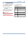
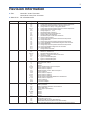
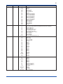
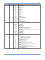
PARAMETERS .......................................................................................... 6-1
6.1
digitalYEWFLO Parameters ............................................................................. 6-1
6.2
Multi-Variable Type (/MV) Parameters............................................................. 6-1
6.3
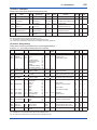
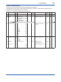
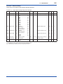
Parameters List ................................................................................................. 6-1
6.4
Parameters Description ................................................................................. 6-11
6.5
Self-Diagnostic (Error Code List) .................................................................. 6-20
OPERATION FOR THE BRAIN TERMINAL (BT200) .............................. 7-1
7.1
Connection Method for the BT200 .................................................................. 7-1
7.2
BT200 Screen and Displaying Flow Rate ....................................................... 7-2
7.3
Setting Parameters using BT200 .................................................................... 7-3
OPERATION VIA HART CONFIGURATION TOOL (HART 5)................. 8-1
8.1
HART Protocol Revision .................................................................................. 8-1
8.2
HART Configuration Tool and Matching of Device Revision ....................... 8-1
8.3
Setting Parameters using DTM ....................................................................... 8-2
8.4
Interconnection between digitalYEWFLO and
HART Configuration Tool ................................................................................. 8-2
8.5
Basic Setup........................................................................................................ 8-2
8.6
Parameter Setting ............................................................................................. 8-3
8.7
Data Renewing and Upload/Download function ........................................... 8-3
8.8
Self-Diagnostic .................................................................................................. 8-3
8.9
Software Write Protect ..................................................................................... 8-3
8.10
Specific Functions of HART Configuration Tool ........................................... 8-3
8.11
9.
8.10.1
Burst Mode ......................................................................................... 8-3
8.10.2
Multidrop Mode .................................................................................. 8-4
8.10.3
Switching HART Protocol Revision ................................................... 8-4
8.10.4
Other Operations for the HART Configuration Tool ........................... 8-5
Menu Tree (HART 5) .......................................................................................... 8-6
OPERATION VIA HART CONFIGURATION TOOL (HART 7)................. 9-1
9.1
HART Protocol Revision .................................................................................. 9-1
9.2
HART Configuration Tool and Matching of Device Revision ....................... 9-1
9.3
Setting Parameters using DTM ....................................................................... 9-1
9.4
Interconnection between digitalYEWFLO and
HART Configuration Tool ................................................................................. 9-2
9.5
Basic Setup........................................................................................................ 9-2
9.6
Parameter Setting ............................................................................................. 9-3
9.7
Data Renewing and Upload/Download function ........................................... 9-3
9.8
Self-Diagnostic .................................................................................................. 9-3
9.9
Software Write Protect ..................................................................................... 9-3
9.10
Specific Functions of HART Configuration Tool ........................................... 9-3
9.10.1
Process Variable Setup (Dynamic Variables) .................................... 9-3
9.10.2
Burst Mode ......................................................................................... 9-4
9.10.3
Event Notification ............................................................................... 9-7
IM 01F06A00-01EN
iii
9.11
10.
10.2
12.
13.
Multidrop Mode .................................................................................. 9-8
9.10.5
Loop Test, Simulation, and Squawk................................................... 9-9
9.10.6
Switching HART Protocol Revision ................................................. 9-12
9.10.7
Other Operations for the HART Configuration Tool ......................... 9-13
Menu Tree (HART 7) ........................................................................................ 9-14
OPERATION ............................................................................................ 10-1
10.1
11.
9.10.4
Adjustment ...................................................................................................... 10-1
10.1.1
Zero Adjustment ............................................................................... 10-1
10.1.2
Span Adjustment .............................................................................. 10-1
10.1.3
Loop Test.......................................................................................... 10-1
10.1.4
Totalizer Start and Totalizer Reset ................................................... 10-2
10.1.5
Setting of Pulse Output (Scaling)..................................................... 10-2
10.1.6
Setting of Burnout Switch................................................................. 10-2
10.1.7
Setting of Write Protect Switch ........................................................ 10-3
10.1.8
Power Failure ................................................................................... 10-3
Adjustment for Manual Mode ........................................................................ 10-3
10.2.1
Low Cut Adjustment ......................................................................... 10-3
10.2.2
Zero Tuning ...................................................................................... 10-3
MAINTENANCE....................................................................................... 11-1
11.1
Changing the Converter and the Terminal Box Orientation....................... 11-2
11.2
Indicator Removal and Rotation.................................................................... 11-3
11.3
Amplifier Unit Removal .................................................................................. 11-3
11.4
Amplifier Unit Assembling ............................................................................. 11-3
11.5
Vortex Shedder Removal ............................................................................... 11-4
11.6
Flow Calculation ............................................................................................. 11-6
TROUBLESHOOTING ............................................................................ 12-1
12.1
Large Errors or Unstable Output................................................................... 12-1
12.2
The Indication Goes to Zero at Certain Time ............................................... 12-1
12.3
No Output When The Fluid is Flowing .......................................................... 12-2
12.4
Output is Indicated at Zero Flow ................................................................... 12-3
12.5
Multi-Variable Type (/MV)................................................................................ 12-4
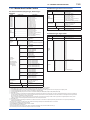
GENERAL SPECIFICATIONS ................................................................ 13-1
13.1
Standard Specifications ................................................................................. 13-1
13.2
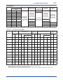
Model And Suffix Codes................................................................................. 13-5
13.3
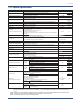
Option Specifications ..................................................................................... 13-8
13.3.1
Option Multi-Variable (Built-In Temperature Sensor)
Type (/MV) .....................................................................................13-10
13.3.2
Option Reduced Bore Type (/R1, /R2) ........................................... 13-11
13.4
Sizing .............................................................................................................. 13-11
13.5
Detailed Accuracy .........................................................................................13-13
13.6
Option Specifications (For Explosion Protected Type) ............................13-20
13.7
External Dimensions ....................................................................................13-22
IM 01F06A00-01EN
iv
14.
15.
EXPLOSION PROTECTED TYPE INSTRUMENT ................................. 14-1
14.1
ATEX ................................................................................................................. 14-1
14.2
FM ..................................................................................................................... 14-5
14.3
IECEx ................................................................................................................ 14-9
14.4
CSA .................................................................................................................14-12
14.5
TIIS ..................................................................................................................14-15
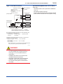
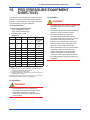
PED (PRESSURE EQUIPMENT DIRECTIVE) ....................................... 15-1
INSTALLATION AND OPERATING PRECAUTIONS FOR TIIS FLAMEPROOF
EQUIPMENT
Revision Information
IM 01F06A00-01EN
1-1
<1. INTRODUCTION>
1.
INTRODUCTION
Thank you for purchasing the digitalYEWFLO
series vortex flowmeter.
To ensure correct use of the instrument, please
read this manual thoroughly and fully understand
how to operate the instrument before operating it.
■ Regarding This Manual
• This manual should be provided to the end
user.
• The contents of this manual may be changed
without prior notice.
• All rights are reserved. No part of this manual
may be reproduced in any form without
Yokogawa’s written permission.
• Yokogawa makes no warranty of any kind with
regard to this material, including, but not limited
to, implied warranties of merchantability and
suitability for a particular purpose.
• All reasonable effort has been made to ensure
the accuracy of the contents of this manual.
However, if any errors or omissions are found,
please inform Yokogawa.
• The specifications covered by this manual are
limited to those for the standard type under the
specified model number break-down and do not
cover custom-made instruments.
• Please note that this manual may not be
revised for any specification changes,
construction changes or operating part changes
that are not considered to affect function or
performance.
• Yokogawa assumes no responsibilities for this
product except as stated in the warranty.
• If the customer or any third party is harmed by
the use of this product, Yokogawa assumes
no responsibility for any such harm owing to
any defects in the product which were not
predictable, or for any indirect damages.
■ Safety and Modification Precautions
• The following general safety precautions must
be observed during all phases of operation,
service, and repair of this instrument. Failure
to comply with these precautions or with
specific WARNINGS given elsewhere in
this manual violates safety standards of
design, manufacture, and intended use of the
instrument. Yokogawa assumes no liability for
the customer’s failure to comply with these
requirements. If this instrument is used in
a manner not specified in this manual, the
protection provided by this instrument may be
impaired.
• Yokogawa will not be liable for malfunctions or
damage resulting from any modification made
to this instrument by the customer.
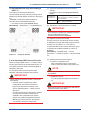
• The following safety symbol marks are used in
this manual and instrument.
WARNING
A WARNING sign denotes a hazard. It calls
attention to procedure, practice, condition or the
like, which, if not correctly performed or adhered
to, could result in injury or death of personnel.
CAUTION
A CAUTION sign denotes a hazard. It calls
attention to procedure, practice, condition or the
like, which, if not correctly performed or adhered
to, could result in damage to or destruction of the
product.
IMPORTANT
An IMPORTANT sign denotes that attention is
required to avoid damage to the instrument or
system failure.
NOTE
A NOTE sign denotes information necessary
for essential understanding of operation and
features.
IM 01F06A00-01EN
<1. INTRODUCTION>
1.1
Using This Instrument Safety
(1) Installation
WARNING
• Installation of the vortex flowmeter must
be performed by expert engineer or skilled
personnel. No operator shall be permitted to
perform procedures relating to installation.
• The vortex flowmeter must be installed within
the specification conditions.
• The vortex flowmeter is a heavy instrument.
Be careful that no damage is caused to
personnel through accidentally dropping
it, or by exerting excessive force on the
vortex flowmeter. When moving the vortex
flowmeter, always use a trolley and have at
least two people carry it.
• When the vortex flowmeter is processing
hot fluids, the instrument itself may become
extremely hot. Take sufficient care not to get
burnt.
• Where the fluid being processed is a toxic
substance, avoid contact with the fluid and
avoid inhaling any residual gas, even after
the instrument has been taken off the piping
line for maintenance and so forth.
• Do not apply excessive weight, for example,
a person stepping on the vortex flowmeter.
• Do not open the cover in wet weather or
humid environment. When the cover is open,
stated enclosure protection is not applicable.
• When opening the cover, wait for more than
2 minutes after turning off the power.
• All procedures relating to installation must
comply with the electrical code of the country
where it is used.
1-2
(2) Wiring
WARNING
• The wiring of the vortex flowmeter must
be performed by expert engineer or skilled
personnel. No operator shall be permitted to
perform procedures relating to wiring.
• When connecting the wiring, check that the
supply voltage is within the range of the
voltage specified for this instrument before
connecting the power cable. In addition,
check that no voltage is applied to the power
cable before connecting the wiring.
(3) Operation
WARNING
• Do not open the cover in wet weather or
humid environment. When the cover is open,
stated enclosure protection is not applicable.
• When opening the cover, wait for more than
2 minutes after turning off the power.
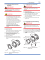
(4) Maintenance
WARNING
• Maintenance of the vortex flowmeter should
be performed by the trained personnel
having knowledge of safety standard. No
operator shall be permitted to perform any
operations relating to maintenance.
• Do not open the cover in wet weather or
humid environment. When the cover is open,
stated enclosure protection is not applicable.
• When opening the cover, wait for more than
2 minutes after turning off the power.
• Always conform to maintenance procedures
outlined in this manual. If necessary, contact
Yokogawa.
IM 01F06A00-01EN
1-3
<1. INTRODUCTION>
(5) Explosion Protected Type Instrument
WARNING
• The instruments are products which have
been certified as explosion protected type
instruments. Strict limitations are applied
to the structures, installation locations,
external wiring work, maintenance and
repairs, etc. of these instruments. Sufficient
care must be taken, as any violation of the
limitations may cause dangerous situations.
Be sure to read Chapter 14 “EXPLOSION
PROTECTED TYPE INSTRUMENT”
before handling the instruments. For TIIS
flameproof type instruments, be sure to
read “INSTALLATION AND OPERATING
PRECAUTIONS FOR TIIS FLAMEPROOF
EQUIPMENT” at the end of this manual.
• Only trained persons use this instrument in
the industrial location.
• Take care not to generate mechanical
spark when access to the instrument and
peripheral devices in hazardous locations.
(6) European Pressure Equipment Directive
(PED)
WARNING
• When using the instrument in compliance
with PED, be sure to read Chapter 15 “PED
(PRESSURE EQUIPMENT DIRECTIVE)”
before use.
1.2
Warranty
• The terms of this instrument that are
guaranteed are described in the quotation.
We will make any repairs that may become
necessary during the guaranteed term free of
charge.
• Please contact our sales office if this instrument
requires repair.
• If the instrument is faulty, contact us with
concrete details about the problem and the
length of time it has been faulty, and state the
model and serial number. We would appreciate
the inclusion of drawings or additional
information.
• The results of our examination will determine
whether the meter will be repaired free of
charge or on an at-cost basis.
■ The guarantee will not apply in the
following cases:
• Damage due to negligence or insufficient
maintenance on the part of the customer.
• Problems or damage resulting from handling,
operation or storage that violates the intended
use and specifications.
• Problems that result from using or performing
maintenance on the instrument in a location
that does not comply with the installation
location specified by Yokogawa.
• Problems or damage resulting from repairs or
modifications not performed by Yokogawa or
someone authorized by Yokogawa.
• Problems or damage resulting from
inappropriate reinstallation after delivery.
• Problems or damage resulting from disasters
such as fires, earthquakes, storms, floods, or
lightning strikes and external causes.
■ Trademarks:
• ‘digitalYEWFLO’, ‘DY’, ‘DYA’, ‘DYC’, and
‘BRAIN TERMINAL’ are registered trademarks
of Yokogawa Electric Corporation. Company
names and product names used in this material
are registered trademarks or trademarks of their
respective owners.
• In this manual, trademarks or registered
trademarks are not marked with ™ or ®.
IM 01F06A00-01EN
<1. INTRODUCTION>
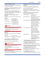
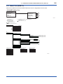
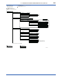
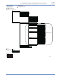
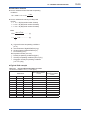
1.3
1-4
ATEX Documentation
This is only applicable to the countries in European Union.
GB
DK
SK
CZ
I
LT
E
LV
EST
NL
PL
SF
SLO
P
H
F
BG
D
RO
S
M
GR
IM 01F06A00-01EN
<2. HANDLING PRECAUTIONS>
2.
HANDLING PRECAUTIONS
digitalYEWFLO Series Vortex Flowmeters are
thoroughly tested at the factory before shipment.
When these instruments are delivered, perform a
visual check to ascertain that no damage occurred
during shipment.
This section describes important cautions in
handling these instruments. Read carefully before
using them.
If you have any problems or questions, contact
your nearest YOKOGAWA service center or sales
representative.
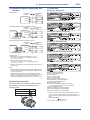
2.1
2-1
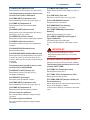
Checking Model and
Specifications
The model and important specifications are
indicated on the name plate attached to the case.
Verify that they are the same as those specified
in the original order, read Chapter 13 “GENERAL
SPECIFICATIONS .” In any correspondence,
always give model (MODEL) and serial number
(NO.) from the name plate.
3UA
2.2
Transportation and Storage
Precautions
If the instrument is to be stored for a long period of
time after delivery, observe the following points.
(1) The instrument should be stored in its original
packing condition in the storage location.
(2) Select a storage location that fulfils the following
conditions:
• A place where it will not be exposed to rain or
water
• A place subject to minimal vibrations or shocks
• Temperature and humidity levels should be as
follows:
Temperature:-40 to +80°C
Humidity:5 to 100% RH (no condensation)
The preferred ambient temperature and
humidity levels are +25°C and approximately
65% RH.
(3) If the digitalYEWFLO vortex flowmeter is
transferred to the installation site and stored
without being installed, its performance may
be impaired due to the infiltration of rainwater
and so forth. Be sure to install and wire the
digitalYEWFLO vortex flowmeter as soon as
possible after transferring it to the installation
location.
(4) The vortex flowmeter is a heavy instrument. Be
careful that no damage is caused to personnel
through accidentally dropping it, or by exerting
excessive force on the vortex flowmeter. When
moving the vortex flowmeter, always use a
trolley and have at least two people carry it.
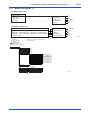
*1)
*2)
F0201.ai
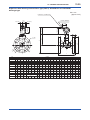
Figure 2.1(a) Example of Name Plate for Integral Type
*1)
*2)
*1)
*2)
F0202.ai
Figure 2.1(b) Example of Name Plate for Remote Type
*1): K factor at + 15°C
*2): The product - producing country.
IM 01F06A00-01EN
3-1
<3. INSTALLATION>
3.
INSTALLATION
(4) Precautions Regarding Piping
WARNING
This instrument must be installed by expert
engineer or skilled personnel. The procedures
described in this chapter are not permitted for
operators.
3.1
Installation Precautions
(1) Ambient Temperature
Avoid an area which has wide temperature
variations. When the installation area is
subjected to heat radiation from process plant,
ensure adequate heat prevention or ventilation.
(2) Atmospheric Conditions
Avoid installing the vortex flowmeter in a
corrosive atmosphere. When the vortex
flowmeter must be installed in a corrosive
atmosphere, adequate ventilation must be
provided
(a) Ensure that the process connector bolts are
tightened firmly.
(b) Ensure that no leak exists in the process
connection pipeline.
(c) Do not apply a pressure higher than the
specified maximum working pressure.
(d) Do not loosen or tighten the flange mounting
bolts when the assembly is pressurized.
(e) Handle the vortex flowmeter carefully when
measuring dangerous liquids, so that the liquids
do not splash into eyes or on face. When using
dangerous gases, be careful not to inhale them.
(5) Other Considerations
• Choose a location where is sufficient clearance
around digitalYEWFLO exist to allow such work
as routine inspections.
• Choose a location that ensures easy wiring and
piping.
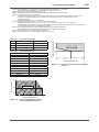
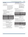
3.2
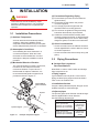
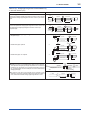
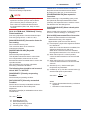
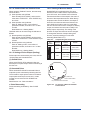
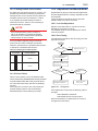
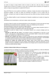
(3) Mechanical Shock or Vibration
The vortex flowmeter is of sturdy construction,
but select an area subject to minimize
mechanical vibration or impact shock. If
the flowmeter is subject to vibrations, it is
recommended that pipeline supports to be
provided as shown in Figure 3.1.
digitalYEWFLO
Vortex Flowmeter
Piping Precautions
Straight Pipe Length and
Recommendations
Read Table 3.1 about Valve Position and Straight
Pipe Length and so on.
● Piping support
Typical vibration immunity level is 1G for normal
piping condition.Piping support should be fixed in
case of over 1G vibration level.
● Installation direction
If a pipe is always filled with liquids, the pipe can be
installed vertically or at inclined angle.
● Adjacent pipes
Pipeline
The process pipline inner diameter should be larger
than the digitalYEWFLO inner diameter.
Use the following adjacent pipe.
Model Code
DY015 up to DY050
DY025/R1 up to DY080/R1
DY040/R2 up to DY100/R2
Pipeline Support
F0301.ai
Figure 3.1
Example of Pipeline Support
DY080 up to DY400
DY100/R1 up to DY200/R1
DY150/R2 up to DY200/R2
Adjacent Pipe
Sch40
or larger inner
diameter than
Sch40
Sch80
or larger inner
diameter than
Sch80
IM 01F06A00-01EN
3-2
<3. INSTALLATION>
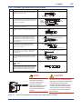
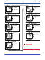
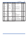
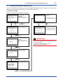
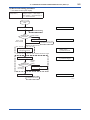
Table 3.1 (a) Straight pipe length and recommendations (1)
D: Nominal diameter (mm)
Description
Reducer pipe:
Ensure the upstream straight pipe length to be 5D or more, and the
downstream straight pipe length to be 5D or more for per reducer
pipe.
Figure
digitalYEWFLO
Flow
Reducer
Expander pipe:
Ensure the upstream straight pipe length to be 10D or more, and
the downstream straight pipe length to be 5D or more for per
expander pipe.
Upstream
Downstream
5D or more
5D or more
digitalYEWFLO
Flow
Upstream
Expander
Downstream
10D or more
5D or more
Bent pipe and straight pipe length:
1. Single bent pipe
1.
Flow
digitalYEWFLO
Upstream
Downstream
10D or more
Flow
2. Double bent pipe; coplanar
2.
5D or more
digitalYEWFLO
Upstream
Downstream
10D or more
Flow
3. Double bent pipe; non coplanar
3.
5D or more
digitalYEWFLO
Upstream
Downstream
20D or more
Valve position and straight pipe length:
Install the valve on the downstream side of the flowmeter.
The upstream straight pipe length dependent on the element
located on the upstream such as reducer/expander, bent and
etc., read description as above. Keep 5D or more for downstream
straight pipe length.
In case the valve has to be installed on the upstream of the
flowmeter, ensure the upstream straight pipe length to be 20D or
more, and the downstream straight pipe length be 5D or more.
5D or more
digitalYEWFLO
Read each element above for
straight pipe run.
Flow
digitalYEWFLO
Valve
Upstream
20D or more
Downstream
5D or more
IM 01F06A00-01EN
3-3
<3. INSTALLATION>
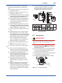
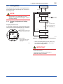
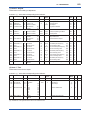
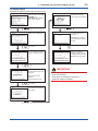
Table 3.1 (b) Straight pipe length and recommendations (2)
D: Nominal diameter (mm)
Description
Figure
Fluid vibration:
digitalYEWFLO
For a gas line which uses a position-type or roots-type blower
compressor or a high-pressure liquid line (about 1MPa or more)
which uses piston-type or plunger-type pump, fluid vibrations may
be produced.
In these case, install valve on the upstream side of digitalYEWFLO.
For inevitable fluid vibration, put a vibration damping device such
as throttling plate or expansion section in the upstream side of
digitalYEWFLO.
digitalYEWFLO
Piston-type or plunger pump:
Install the accumulator on the upstream side of digitalYEWFLO to
reduce fluid vibrations.
digitalYEWFLO
Valve positon (T-type piping exist):
When pulsation causes by a T-type piping exist, install the valve on
the upstream of the flowmeter.
Example: As shown in the figure, when the valve V1 is turned off,
the fluid flow throught B as to meter A the flow is zero. But due to
the pulsating pressure is detected, the meter is zero point become
fluctuating. To avoid this, change the valve V1 location to V1'.
Relocating
Valve (Off)
B
V1’
V1
A
Note: In case of the Reduced Bore Type, moisture may be
remained upstream of the flowmeter. Drain it appropriately.
Pressure and Temperature Taps:
When the temperature/pressure correction, place a pressure tap in
a position on the downstream side 2 to 7D from digitalYEWFLO.
Then place a temperature tap in a position on the downstream side
1 to 2D from a pressure tap.
When use a temperature tap only, place it in a position on the
downstream side 3 to 9D from digitalYEWFLO.
digitalYEWFLO
Flow
Pressure tap
Temperature tap
digitalYEWFLO
Upstream
Flow
Downstream
2 to 7D
Mounting Gasket:
1 to 2D
digitalYEWFLO
Avoid mounting gaskets which protrude into the pipe line. This may
cause inaccurate readings.
Use the gaskets with bolt holes, even if digitalYEWFLO is the wafer
type.
When using a spiral gasket (without bolt holes), confirm the size
with the gasket -manufacturer, as standard items may not be used
for certain flange ratings.
Pipeline Flange
Pipeline
No good
IM 01F06A00-01EN
3-4
<3. INSTALLATION>
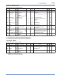
Table 3.1 (c) Straight pipe length and recommendations (3)
Description
Figure
Heat-Insulation:
When an integral-type flowmeter or a remote type detector is
installed and the pipe carrying higt-temperature fluids is heatinsulated, do not wrap adiabatic materials around the installation
the bracket (DY015 to DY100) or the nozzle (DY150 to DY400) of
the converter.
digitalYEWFLO
digitalYEWFLO
Nozzle
Heat-Insulator
Bracket
Heat-Insulator
Note: Read Section 3.4 "Cryogenic and High Process Temperature
Version Insulation" and install it rightly.
[DY015 to DY100]
Flushing of the pipe line:
[DY150 to DY400]
digitalYEWFLO
Flush and clean scale, incrustation and sludge on the inside of
pipe for newly installed pipe line and repaired pipe line before the
operation. For flushing, the flow should flow through bypass-piping
to avoid damaging the flowmeter. If there is no bypass-piping,
install short pipe instead of the flowmeter.
Short pipe
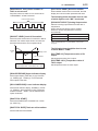
(2) Liquid Measurement Precautions
Mounting Precautions
To insure accurate measurement, the
digitalYEWFLO must always have a full pipe.
WARNING
• Piping Requirements for Proper Operation
Allow the flow to flow against gravity. When
the flow is moving with gravity, lift the downstream pipe length above the digitalYEWFLO
installation level to maintain full pipeline.
In case of high process temperature, care
should be taken not to burn yourself because
the surface of body and case reach a high
temperature.
(1) Gas or Steam Measuring Precautions
• Piping to Prevent Standing Liquid
Mount digitalYEWFLO in a vertical pipeline
to avoid liquid traps. When digitalYEWFLO
is installed horizontally, raise that part of
the pipeline in which the digitalYEWFLO is
installed.
Flow
(No Good)
Flow
(Good)
h h>0
(Good)
Flow
Flow
(Good)
(No Good)
(Good)
h
h>0
Flow
F0303.ai
Flow
(No Good)
Flow
F0302.ai
IM 01F06A00-01EN
3-5
<3. INSTALLATION>
•
Piping for Avoiding Bubbles
(4) Pipeline Diameter and digitalYEWFLO
Flows containing both gas and liquid cause
problems. Avoid gas bubbles in a liquid flow.
Piping should be carried out to avoid bubble
generation.
Install the valve on the downstream side of the
flowmeter because pressure drop across the
control valve may cause gas to come out of the
solution.
(Good)
Control
Value
The process pipeline inner diameter should be
slightly larger than the vortex flowmeter inner
diameter, schedule 40 or lower pipe should be
used for 1/2 to 2 inch flowmeters and schedule
80 or lower pipes for 3 to 16 inch flowmeters.
(No Good)
(No Good)
D1
(Good)
D2
D1
D1 < D2
D2
D1 D2
F0306.ai
Flow
(5) Waterproof Construction
(Good)
The vortex flowmeter is of IP67, Type 4X, JIS C
0920 watertight protection. However, it cannot
be used under water.
Flow
3.3
Maintenance of Piping
(1) Pipe cleaning
Flow
(No Good)
F0304.ai
(3) Multi-Phase Flow
digitalYEWFLO can measure gas, liquid
and steam when there is no change in state.
However, accurate measurement of mixed
flows (e.g. gas and liquid) is not possible.
(No Good)
• Flushing of pipe line (Cleaning)
Flush and clean scale, incrustation and sludge
on the inside of pipe wall for newly installed pipe
line and repaired pipe line before the operation.
• Fluid Carrying Solids
Do not measure fluids that carry solids
(e.g. sand and pebbles). Make sure users
periodically remove solids adhering to the
vortex shedder.
• Obstruction of flow fluids may cause to make
a chemical reaction and the fluid will be
crystallized and hardened, and be deposited on
the pipe wall and shedder bar.
In those cases, clean shedder bar.
(2) Bypass piping
Mist flow
Bypass piping is convenient for the
maintenance of digitalYEWFLO (vortex
shedder cleaning, etc.).
(No Good)
Liquid
Flow
Bypass shut-off valve
Stratified flow
digitalYEWFLO
(No Good)
Flow
Upstream shut-off valve
Downstream shut-off valve
F0307.ai
Gas Flow
Bubble flow
F0305.ai
IM 01F06A00-01EN
3-6
<3. INSTALLATION>
3.4
Cryogenic and High Process
Temperature Version
Insulation
When you are using Cryogenic and High Process
Temperature version of digitalYEWFLO Vortex
Flowmeter (Option code: /HT, /LT), read following
contents.
CAUTION
Keep the upper limit of heat insulating material to
prevent overheating of the terminal box.
Seal the Heat-Insulator to avoid hot-air leakage.
50mm min.
Installing Cryogenic Version
For cryogenic applications, use stainless steel
mounting bolts and nuts to install the flowmeter.
These can be ordered separately from
YOKOGAWA. Cover the flowmeter body with
heat insulating material so that the flowmeter
can be maintained at ultra-low temperatures.
UPPER LIMIT OF
Heat-Insulator
50mm min.
UPPER LIMIT OF
Heat-Insulator
Nominal Size: 100mm or under
Nominal Size: 150mm or over
F0309.ai
Maintenance for Cryogenic Applications
Option code: /LT uses special materials
that produce vortex flowmeter for cryogenic
applications. When you are replacing a shedder
bar, specify Cryogenic Version shedder bar. To
avoid condensing in the terminal box, ensure
that the wire connecting port is well sealed.
Bracket
Cold insulating material
Maintenance for High Process
Temperature Applications
Option code: /HT uses special materials that
produce vortex flowmeter for High Process
Temperature applications When you are
replacing a shedder bar or a gasket, specify
High Process Temperature Version.
3.5
Mounting Procedures
WARNING
F0308.ai
Installing High Process Temperature
Version
Installation of the flowmeter is the same as the
standard type. Cover the flowmeter body with
heat insulating material following instruction of
“CAUTION”.
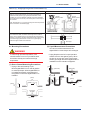
The Vortex Flowmeter is a heavy instrument.
Please be careful to prevent persons from
injuring whin it is handled.
Before installing the instrument verify the following.
The direction of flow should match to the arrow
mark on the instrument body. When changing the
orientation of the terminal box, read Chapter 11
“MAINTENANCE.”
1. Installation of Vortex flowmeter of the wafer and
flange type is shown in Table 3.3.
When installing the wafer type vortex flowmeter,
it is important to align the instrument bore with
the inner diameter of the adjacent piping.
To establish alignment, use the four collars
supplied with the instrument.
IM 01F06A00-01EN
3-7
<3. INSTALLATION>
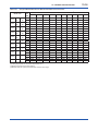
• Four collars are supplied for 1/2 inch (15mm) to
1- 1/2inch (40mm), 2 inch of JIS 10K or ANSI
class 150, and 3 inch of ANSI class 150. Install
the instrument as illustrated in Table 3.3.
• If the adjacent flanges have eight bolt holes,
insert the stud bolts in the holes on the
instrument shoulder.
• Stainless steel stud bolts and nuts are available
on order. When they are to be supplied by the
user, read Table 3.2 for stud bolt length. Gaskets
must be supplied by the user.
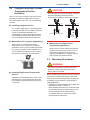
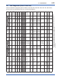
Table 3.2 Flange Rating
Size
mm
(inch)
Major Diameter of
External Threed Length
of Stud Bolt d
(mm)
(mm)
Flange Rating
15mm JIS 10K, 20K/DIN 10,
(1/2B) 16,25,40
JIS 40K
ANSI 150, 300, 600
12
16
12.7
160
160
155
25mm JIS 10K, 20K, 40K
(1B) ANSI 150
ANSI 300, 600
DIN 10, 16, 25, 40
16
12.7
15.9
12
160
155
160
160
16
20
12.7
19.1
160
170
155
170
50mm JIS 10K, 20K, 40K/ DIN
(2B) 10, 16, 25, 40 ANSI
150, 300, 600
16
15.9
200
200
80mm JIS 10K/DIN 10, 16,
(3B) 25, 40
JIS 20K, 40K
ANSI 150
ANSI 300, 600
16
20
15.9
19.1
220
240
240
240
100mm JIS 10K/DIN 10, 16
(4B) JIS 20K/DIN 25, 40
JIS 40K
ANSI 150
ANSI 300
ANSI 600
16
20
22
15.9
19.1
22.2
220
240
270
240
240
270
40mm JIS 10K, 20K/DIN 10,
(1-1/2B) 16, 25, 40
JIS 40K
ANSI 150
ANSI 300, 600
Pipeline Flange
Pipeline
F0311.ai
2. Avoid mounting gaskets which protrude into the
pipeline. This may cause inaccurate readings.
Use gaskets with bolt holes, even if
digitalYEWFLO is of the wafer type.
When using a spiral gasket (without bolt holes),
confirm the size with the gasket-manufacturer,
as standard items may not be used for certain
flange ratings.
Length "
d
Collar
Stud Bolt
F0310.ai
IM 01F06A00-01EN
3-8
<3. INSTALLATION>
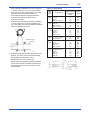
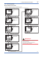
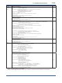
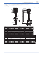
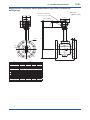
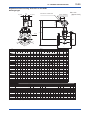
Table 3.3 (a) Installation of Wafer Type Vortex Flowmeter
Description
Wafer type
When Installation Collar are required, the
installation vortex flowmeters applied to the
following line sizes and flange ratings.
Horizontal Installation
Electrical
Connection
Flange
Flange Rating
Size mm (inch)
15 to 40
(1/2 to 1-1/2)
Flow
Direction
All ratings
50(2)
JIS 10K, ANSI class 150,
DIN PN10 to PN40
80(3)
ANSI class 150
Flange
Nut
Bolt (4 pcs.)
Gasket
Collar (4 pcs.)
Gasket
Nut
Vertical Installation
WARNING
Nut
Gasket
The inside diameter of the gasket must
be larger than the pipe inner diameter
so that it will not disturb the flow in the
pipeline.
Flange
Collar (4 pcs.)
Electrical
Connection
WARNING
Gasket
When installing the Flowmeter vertically in the
open air, change the electrical connection port
direction to the ground. If the electrical
connection port is installed upwards, rain
water might leak in.
Flange
Bolt (4 pcs.)
Nut
WARNING
Flow Direction
In case of vertical installation, two collars in
the upper part might move after the
installation. But it doesn't influence the
performance, please use the flowmeter under
such condition.
(1) Insert two collars on each two bolts of bottom side of the flowmeter.
(2) Fit the flowmeter body to the collars. And tighten the four bolts and nuts
uniformly.
(3) Check for leakage from the flange connections.
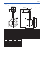
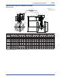
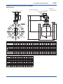
Horizontal Installation
When Installation Collars are not required,the
installation vortex flowmeters applied to the
following line sizes and flanges.
Size mm (inch)
Flange Rating
50(2)
JIS 20K, 40K
ANSI class 300,600
80(3)
JIS 10K, 20K, 40K
ANSI class 300, 600
100(4)
JIS 10K, 20, 40K
ANSI class 150, 300, 600
Vertical Installation
Electrical Connection
Flow
Direction
Bolt Hole
Flange
Nut
Stud Bolt (8 pcs.)
Flange
Gasket
Gasket
Nut
(1) Insert two stud bolts in the bolt holes
on the flowmeter shoulder to align
the instrument body with the inner
diameter of the adjacent piping.
(2) Tighten all bolts uniformly and check
that there is no leakage between the
instrument and the flanges.
Electrical
Connection
Flow Direction
F0312.ai
IM 01F06A00-01EN
3-9
<3. INSTALLATION>
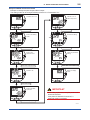
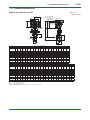
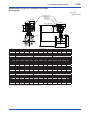
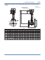
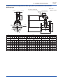
Table 3.3 (b) Installation of Flange Type Vortex Flowmeter
Flange type
Description
Use the stud bolts and nuts supplied with the
flowmeter of the user.
The gaskets should be supplied by the user.
Horizontal Installation
Flow Direction
Flange
Flange
Nut
CAUTION
Stud Bolt
The inside diameter of the gasket must be
larger than the pipe inner diameter so that it
will not disturb the flow in the pipeline.
Gasket
Nut
Gasket
Flow Direction
Vertical Installation
F0313.ai
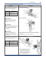
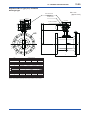
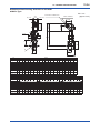
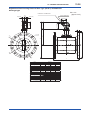
Table 3.3 (c) Installation of Remote Type Converter
Remote type converter
CAUTION
A signal cable (DYC) is used between the
remote type flowmeter and the converter.
The maximum signal cable length is 97.5ft
(30m).
Description
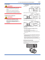
The converter is mounted on a 2-inch (60.5mm outer dia.) stanchion or horizontal
pipe.
Do not mount the converter on a vertical pipe. It makes wiring and maintenance
difficult.
The converter mounting orientation can be changed as illustrated below.
Stanchion Mounting
Horizontal Pipe Mounting
Nut
Bracket
2-inch Pipe
U-Bolt
F0314.ai
IM 01F06A00-01EN
4-1
<4. WIRING>
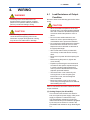
4.
WIRING
WARNING
The wiring of the vortex flowmeter must
be performed by expert engineer or skilled
personnel. No operator shall be permitted to
perform procedures relating to wiring.
CAUTION
Once all wiring is complete, check the
connections before applying power to the
instrument. Improper arrangements or wiring
may cause a unit malfunction or damage.
4.1
Load Resistance of Output
Condition
Be sure to observe the following precautions when
wiring:
CAUTION
• When the ambient temperature of the wire
exceeds +60°C, use heat-resistant insulated
wire with a maximum allowable temperature
more than ambient temperature +30°C or
above.
• Do not connect cables outdoors in wet
weather in order to prevent damage from
condensation and to protect the insulation.
• Do not splice the cable between the flowtube
terminal and the converter if it is too short.
Replace the short cable with a cable that is
the appropriate length.
• All the cable ends must be provided with
round crimp-on terminals and be securely
wired.
• Be sure to turn power off before opening the
cover.
• Before turning the power on, tighten the
cover securely.
• Explosion protected types must be wired in
accordance with specific requirement (and,
in certain countries, legal regulations) in
order to preserve the effectiveness of their
explosion protected features.
• The terminal box cover is locked by the
Locking Screw. In case of opening the
terminal box cover, use the hexagonal
wrench attached.
• Be sure to lock the cover by the Locking
Screw using the hexagonal wrench attached
after installing the cover.
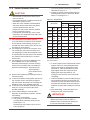
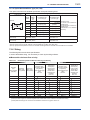
Table 4.1 shows the connection method of several
output conditions.
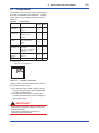
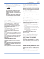
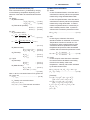
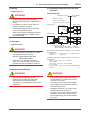
(1) Analog Output (4 to 20 mA DC)
This converter uses the same two wires for
both, the signal and power supply. A DC power
supply is required in a transmission loop.
The total leadwire resistance including the
instrument load and power distributor (supplied
by the user) must conform to a value in the
permissible load resistance range. Read Figure
4.1.
IM 01F06A00-01EN
4-2
<4. WIRING>
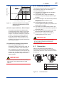
4.2
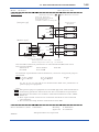
Load resistance R ()
600
R=
E–10.5
0.0236
Communication
Applicable range
BRAIN and HART
250
10.5
16.4
24.7
30
Power Supply Voltage E (V)
Figure 4.1
42
F0401.ai
Relationship between Power Supply
Voltage and Load Resistance (4 to 20
mA DC Output)
(2) Pulse output and Alarm, Status Output
This version uses three wires between the
converter and the power supply. A DC power
and load resistance are required, and pulse
output is connected to a totalizer or an electric
counter. Low level of the pulse output is 0
to 2V. No communication is possible over
a transmission line. Communication via the
amplifier board is always possible irrespective
of the wiring condition.
(3) Simultaneous Analog-Pulse Output
When using digitalYEWFLO in the
simultaneous analog -pulse output mode, the
communicable distance of the transmission
line is restricted on the wiring method. Table
4.1 shows the examples of connection for this
output mode. Communication via the amplifier
board is always possible irrespective of the
wiring condition.
Selection of Wires
The following should be taken into consideration
when selecting cables for use between the
converter and distributor.
(1) Use 600V PVC insulated wire or equivalent
standard wire or cable.
(2) Use shielded wire in areas susceptible to
electrical noise (both analog and pulse output
versions).
(3) In areas with high or low ambient temperatures,
use wires or cables suitable for such
temperatures.
(4) In atmospheres where oils or solvents,
corrosive gases or liquids may be present, use
suitable wires or cables.
(5) Use cable which withstand temperature up to
+60°C and more, when ambient temperature is
more than +60°C.
(6) The outer diameter of the screw for grounding
terminal and the cable terminal is 4mm.
(7) Recommend a crimping terminal with an
insulating sleeve (for 4mm screw).
IMPORTANT
For the remote type, use DYC signal cable
to connect the converter and remote type
flowmeter(DY-N).
4.3
Connection
Table 4.1 shows the connection sample of
connection for power supply and load resistance.
The terminal position of each connection is shown
in Figure 4.2.
IMPORTANT
For pulse output and the simultaneous analogpulse output ,use the load resistance. Read
Table 4.1.
Remote type
Integral type
Supply
4 to 20 mA DC Output Power Supply
and Output Signal Terminals
Pulse
Pulse Output Terminal
+
–
+
Grounding Terminal
F0402.ai
Figure 4.2
Terminal Position
IM 01F06A00-01EN
4-3
<4. WIRING>
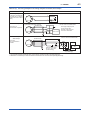
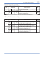
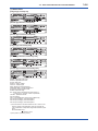
Table 4.1 (a) The wiring example for the analog and pulse and status, alarm output.
Connection
Analog Output
In this case, Communication
is possible (up to a distance
of 2km when a CEV cable is
used.)
Description
digitalYEWFLO Electrical Terminal
SUPPLY
In this case, No
communication is possible.
Status Output
Alarm Output
In this case,
No communication is
possible.
+
–
PULSE
Pulse Output
+
–
+
Distributor
24V DC
250Ω
digitalYEWFLO Electrical Terminal
Shielded Cable
SUPPLY
+
PULSE
+
Use the Three-wire shielded cable.
E
–
*2 R
*1
Electric counter
digitalYEWFLO Electrical Terminal
Use the Three-wire shielded cable.
Shielded Cable
SUPPLY
E
+
Relay
–
PULSE
This supply voltage requires
a power sourse with a
maximum output current of
no less than E/R+25mA.
+
External Power supply
30V DC, 120mA max
(Contact Rating)
Magnetic
valve
AC power supply
*1: To avoid the influence of external noise, use an electric counter which fits to the pulse frequency.
*2: Resistor is not necessary in case of an electric counter which can receive contact pulse signal directly.
IM 01F06A00-01EN
4-4
<4. WIRING>
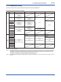
Table 4.1 (b) The wiring example for the simultaneous analog and pulse output, the calculation formula of the
range of load registance R for the pulse output.
Connection
Simultaneous
Analog
-Pulse Output *3
Example 1
In this case, Communication
is possible(up to a distance
of 2km when a CEV cable is
used).
Description
When analog and pulse output are used, the length of communication line is subjected to wiring conditions. Read
example 1 to 3. If the communication carries out from amplifier, no need to consider wiring conditions.
Shield
Shielded Cable
+
–
PULSE +
SUPPLY
Distributor (or communication medium)
24V DC
Outer Jacket
(R)*2
250
E(10.5 to 30V DC)
Counting input
Common
digitalYEWFLO Electrical Terminal
For the shielded cables in this
example of flowmeter installation,
use two-wire separately
shielded cables. *4
This supply voltage requires a
power sourse with a maximum
output current of no less than
E/R.
Electric counter *1 (or communication medium)
Example 2
In this case, Communication
is possible (up to a distance
of 200m when a CEV cable
is used) and R = 1kΩ).
Recorder or
other instrument
Shield
Shielded Cable
SUPPLY
PULSE
+
–
+
(R)*2
Outer Jacket
Counting input
Common
Electric counter *1
(or communication medium)
digitalYEWFLO Electrical Terminal
Example 3
In this case, No communi
-cation is possible (when
shielded cable is not used).
Recorder or
other instrument
SUPPLY
PULSE
+
–
+
(R)*2
E(16.4 to 30V DC)
Counting input
This supply voltage requires
a power sourse with a
maximum output current of
no less than E/R+25mA.
Common
Electric counter *1
(or communication medium)
digitalYEWFLO Electrical Terminal
The range of load
resistance R for the
pulse output.
E(16.4 to 30V DC)
For the shielded cables in this
example of flowmeter installation,
use two-wire separately shielded
cables. *4
This supply voltage requires a
power sourse with a maximum
output current of no less than
E/R+25mA.
The supply voltage requires output
impedance no more than 1/1000
of R (load resistance).
The load resistance should be selected by calculation as shown below.
E (V)*5
120
P (mW) =
R (k)
2
E (V)
R (k)
0.1
C ( μF ) × f ( kHz )
Example of CEV cable capacitance
0.1μF/km
Where
E = Supply voltage (V)
f = Frequency of pulse output (kHz)
R = Value of load resistance (k)
C = Cable capacitance (μF)
P = Power ratio of the load resistance
(mW)
*1: To avoid the influence of external noise, use an electric counter which fits to the pulse frequency.
*2: Resistor is not necessary in case of an electric counter which can receive contact pulse signal directly.
*3: When using analog and pulse output simultaneously, the HART communication may be influenced by noise comparing analog output
only.
*4: Signal Cable for ADMAG AXF, AXFC-0 (No Termination) is available.
E(V)
*5:
Option code: /KS2, /SS2
80
IM 01F06A00-01EN
4-5
<4. WIRING>
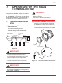
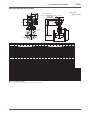
4.4
Connection of DYC Remote
Type Signal Cable
The DYC remote type signal cable is shown in
Figure 4.3 and Figure 4.4, and the terminal is
shown in Figure 4.5.
The maximum cable length is 30 m (97.5 feet).
Remove terminal box cover and wiring connection
dust-cap before wiring.
For remote type converter has two electrical
connections (cable inlets). Use the left connection
as viewed from the terminal box for the DYC remote
type signal cable and the right connection for the
transmission cable.
If a signal cable kit is supplied by YOKOGAWA,
both ends of the cable must be finished in
accordance with the following instructions. Read
Section 4.5 “End Processing Method of DYC
Remote Type Signal Cable“.
T
T
A
A
B
B
C
C
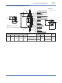
Remote Type Detector (DY-N)
DYA Remote Type Converter
DYC
C
T: Only for /MV
B
T
A
Remote Type Detector (DY-N.../E1)
Input Terminal from builtT in temperature sensor
A Input Terminals from
B vortex detector
C Common Terminal
F0405.ai
Figure 4.5
Terminal of Detector and Converter
DYC Remote Type
Signal Cable
DYA Remote Type
Converter
CAUTION
After completing the signal cable connections,
install the shielded cover to signal cable terminal
as shown in Figure 4.6.
Shield Cover
Unit : mm
C
B
A
T
(Black) (White) (Red) (Yellow)
T
A
B
C
(Yellow) (Red) (White) (Black)
70
60
50
20
Flowmeter
80
70
60
50
F0406.ai
25
Specified
Length (L)
30m (max.)
95
(Blue)
Figure 4.6
Shielded Cover
Converter
80
Power Cable
DYC
T: Only for / MV
Figure 4.3
F0403.ai
DYC Remote Type Signal Cable
Outer shield
To Flowmeter
(Yellow) T
(Red) A
(White) B
Inner shield
(Black) C
To Converter
T (Yellow)
A (Red)
B (White)
C (Black)
(Bule)
T: Only for / MV
Figure 4.4
F0404.ai
Construction of DYC Remote Type
Signal Cable
IM 01F06A00-01EN
4-6
<4. WIRING>
4.5
End Processing Method of DYC Remote Type Signal Cable
4.5.1 For Remote Type Vortex Flowmeter (DY-N)
Description
Figure
Strip off the outer polyethylene jacket, outer braided
shield and inner jacket, and inner braided shield as
per the dimensions below.
1
5 (0.2) 10 (0.4)
Unit : mm
(approx. inches)
5 (0.2)
90 (3.5)
Conductive Layer (Black)
T*1 (Yellow)
Strip off the black conductive layer convering two
wires completely, as per the dimensions below.
Twist each of the conductor and drain wires so that
there are no free strands.
2
T*1 (Yellow)
A (Red)
40 (1.6) 5 (0.2)
3 (0.1)
or less
50 (2.0)
60 (2.4)
Conductive Layer (Black)
B (White)
3
Do not short-circuit the conductive layer and the
terminals (A, B, C and T*1).
4
Strip off about 5 mm (0.2 in.) of insulation for each
of wires A, B, and T*1, and twist the strands of each
wire. Twist the inner and outer drain wires together.
Drain wires
1
C (Black) T* (Yellow)
A (Red)
B (White)
5 (0.2)
Slide FEP (fluorinated ethylene propylene) tubing
over the twisted inner and outer drain wires C until
the tubing cannot be slid any further, and then cut
off the tubing leaving 5 mm (0.2 in.) of the stranded
drain wires exposed.
5
Slide heat shrinkable tubing over the cable end so
that the tubing covers the braided shield and
overlaps both the polyethylene jacket and loose
wires A, B, C, and T*1.
6
Slide a short piece of heat shrinkable tubing over
each of wires A, B, C, and T*1. Install a crimp-on
terminal lug at the tip of each wire. Crimp and
solder each lug.
7
5 (0.2)
5 (0.2)
5 (0.2)
C (Black)
FEP Insulation Tubing
(Black)
T*1 (Yellow)
A (Red)
B (White)
C(Black)
Heat Shrinkable Tubing
T*1 (Yellow)
A (Red)
B (White)
Crimp and Solder Here
Heat Shrinkable Tubing
Lug tip
10
Slide each short piece of heat shrinkable tubing
over the crimp sleeve. Heat all pieces of heat
shrinkable tubing with a heat blower or dryer.
8
Heat Shrinkable Tubing
Attach an identification label to the end of the cable.
9
NOTE
Check that the insulation resistance between each
wire including the inner shield is 10M or greater at
500V DC. Ensure that both ends of the wires are
disconnected (open-circuited) during the check.
F0407.ai
(*1): Only for /MV
NOTE
80 (3.15)
Black
(C)
White
(B)
20 (0.79)
Unit : mm
(approx. inches)
Red (A)
Yellow*1(T) 50 (1.97)
60 (2.36)
70 (2.76)
Figure 4.7
F0408.ai
In case that the cable end finish
parts assembly is necessary
after delivery, contact your
nearest Yokogawa sales office
or the sales representative
from which you purchased the
product.
CAUTION
Do not touch the '' conductive layer"
(black area covering the signal cables A
and B) to the converter case, terminal,
and other leadwires. If it is touched,
operation of the converter may be
incorrect. When the cable is terminated,
remove the conductive layer properly.
End Processing Method of DYC Remote Type Signal Cable for Detector
IM 01F06A00-01EN
4-7
<4. WIRING>
4.5.2 For Remote Type Vortex Flow Converter (DYA)
1
Description
Figure
Strip off the outer polyethylene jacket, outer braided
shield and inner jacket, and inner braided shield as
per the dimensions as shown.
15 (0.6) 10 (0.4)
Conductive
Layer (Black)
2
Cut of the black conductive layers(convering the
two wires) completely, as per the dimensions below.
Twist each of the conductor and drain wires so that
there are no free strands.
3
Do not short-circuit the conductive layer and the
terminals (A, B, C, G, and T*1).
4
Strip off about 5 mm (0.2 in.) of insulation for each
of wires A, B, and T*1, and twist the strands of each
wire.
95 5 (0.2)
(3.7)
T*1 (Yellow)
B (White)
3 (0.1) or less
40 (1.6)
50 (2.0)
60 (2.4)
A (Red)
T (Yellow)
*1
6
Slide black FEP (fluorinated ethylene propylene)
tubing over the inner shield drain wire C and blue
FEP tubing over outer shield drain wire G until
the tubing cannot be slid any further, and then cut
off the tubing leaving 5 mm (0.2 in.) of the drain
wires exposed.
Slide heat shrinkable tubing over the cable end so
that the tubing covers the braided shield and
overlaps both the polyethylene jacket and loose
wires A, B, C, G, and T*1.
5 (0.2)
Conductive
Layer (Black)
5 (0.2)
G
C
5 (0.2)
Drain wires
T*1 (Yellow)
A (Red)
B (White)
5 (0.2)
5
Unit : mm
(approx. inches)
5 (0.2)
G
FEP Insulation Tubing (Black)
FEP Insulation Tubing (Blue)
C (Black)
T*1 (Yellow)
A (Red)
B (White)
5 (0.2)
G
C (Black) (
A Red) T
B (White)
15 (0.6)
25 (1.0)
Heat Shrinkable Tubing
7
Slide a short piece of heat shrinkable tubing over
each of wires A, B, C, G, and T*1. Install a crimp-on
terminal lug at the tip of each wire. Crimp and
solder each lug.
8
Slide each short piece of heat
shrinkable tubing over the crimp sleeve. Heat all
pieces of heat shrinkable tubing with a heat blower
or dryer.
9
Attach an identification label to the end of the cable.
Crimp and Solder
Lug-Tips
Heat-shrinkable tubing
10
(0.4)
Heat Shrinkable Tubing
NOTE
Check that the insulation resistance between each
wire including the inner shield is 10M or greater at
500V DC. Ensure that both ends of the wires are
disconnected (open-circuited) during the check.
F0409.ai
(*1): Only for /MV
NOTE
Unit : mm
(approx. inches)
95 (3.74)
Blue (G)
Black (C)
White (B)
Red (A)
3
MAX
Yellow*1(T) 50 (1.97)
60 (2.36)
25 (0.98)
70 (2.76)
80 (3.15)
Figure 4.8
F0410.ai
In case that the cable end
finish parts assembly is
necessary after delivery,
contact your nearest
Yokogawa sales office or the
sales representative from
which you purchased the
product.
CAUTION
Do not touch the '' conductive layer"
(black area covering the signal cables
A and B) to the converter case,
terminal, and other leadwires. If it is
touched, operation of the converter
may be incorrect. When the cable is
terminated, remove the conductive
layer properly.
End Processing Method of DYC Remote Type Signal Cable for Converter
IM 01F06A00-01EN
4-8
<4. WIRING>
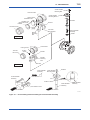
4.6
Wiring Procedures and
Precautions
Terminal Box
NOTE
Once all wiring is complete, check the
connections before applying power to the
instrument. Improper arrangements or wiring
may cause a unit malfunction or damage.
Steel Conduit for
Flameproof
Converter
(1) Lay wiring as far as possible from electrical
noise sources such as large capacity
transformers, motors, and power supplies.
(2) Remove the terminal cover and dustproof plug
of an electrical connection before wiring. When
you open the cover of explosion protected
type (*), turn the Locking Screw to the right, and
unlock. When you close a cover after wiring, be
sure to turn the Locking Screw to the left and
lock.
(*) Flameproof (TIIS, ATEX, IECEx)
(3) It recommends using an flexible metal conduit
and a duct for waterproofing or external
protection of an electric wire. Read Figure 4.9
and Figure 4.10.
(4) The flameproof packing adapter (option
code: /G11 or /G12) should be used for
the external wiring of TIIS Flameproof.
Read “INSTALLATION AND OPERATING
PRECAUTIONS FOR TIIS FLAMEPROOF
EQUIPMENT.”
Flexible Metal Conduit
Tee
Drain Fitting
F0412.ai
Figure 4.10
Example of Wiring (DYA Remote Type
Converter)
B. Coupling
Wrench
Lock Nut
Clamp Nut
Clamp Ring
Packing Gland
Washer
Cable
Packing
Wrench
Union Nut
Lock Nut
Packing Case
Adapter Body
O-Ring
Terminal Box
Apply a nonhardnening
sealant to the threads
for watweproofing
F0413.ai
Figure 4.11
Cable Wiring
NOTE
Steel Conduit
Flameproof
Converter
Be sure to use the flameproof packing adapter
(option code: /G11 or /G12) for TIIS flameproof
type at the time of cable wiring work. Read Table
4.2.
Tee
Table 4.2
Flameproof packing adaptor
Flexible Metal Conduit
Option Code
Drain Fitting
Diameter for
screw
F0411.ai
Figure 4.9
Example of Wiring (Integral Type and
Remote Type Detector (DY-N))
G11
G11
G12
G12
Cable outer
diameter
mm (inch)
ø8.0 to ø10.0
(ø0.31 to ø0.39)
ø10.0 to ø12.0
(ø0.39 to ø0.47)
Identification
mark
Parts NO.
16 8-10
G9601AM
16 10-12
IM 01F06A00-01EN
4-9
<4. WIRING>
(5) Perform attachment of flameproof packing
adaptor in the following ways. Read Figure
4.11.
(a) Loosen the locking screw and remove the
terminal box cover.
(b) Measure the cable outer diameter in two
directions to within 0.1 mm.
(c) Calculate the average of the two diameters,
and use packing with an internal diameter
nearest to this value. Read Table 4.2.
(d) Screw the flameproof packing adapter into
the terminal box until the O-Ring touches
the wiring port (at least 6 full turns), and
firmly tighten the lock nut.
(e) Insert the cable through the union nut, the
B. coupling, the clamp nut, the clamp ring,
the packing gland, the washer, the packing,
and the packing case, in that order.
(f) Insert the end of the cable into the terminal
box.
(g) Tighten the union cover to grip the cable.
When tightening the union cover, tighten
approximately one turn past the point where
the cable will no longer move up and down.
Proper tightening is important. If it is too
tight, a circuit break in the cable may
occur; if not tight enough, the flameproof
effectiveness will be compromised.
(h) Fasten the cable by tightening the clamp
nut.
(i) Tighten the lock nut on the union nut.
(j) Connect the cable wires to each terminal.
(6)
(a) Do not connect cables outdoors in wet
weather in order to prevent damage from
condensation and to protect the insulation.
(b) Do not splice the cable between the
flowtube terminal and the converter if it is
too short. Replace the short cable with a
cable that is the appropriate length.
(c) The signal cables must be routed in
separate steel conduit tubes 16 (JIS C
8305) or flexible conduit tubes 15 (JIS C
8309).
(d) Always route the power and output signal
cables in separate steel conduit tubes,
except when the power supply voltage is 24
V and four-core cables are used for wiring.
Keep conduits or flexible tubes watertight
using sealing tape.
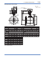
(7) For the TIIS flameproof type with wiring using
a flameproof packing adapter, wire cables
through the packing adapters approved by
Yokogawa (option code: /G11 or /G12).
T1
Adapter body (M. Screw)
O-Ring
Unit : mm
(approx. inch)
Packing case
16.5
Hexagon socket set screw
Packing *
18
Hexagon socket set screw
O-Ring
L
F
O-Ring
Washer
G
C
Union nut
Packing gland
*Packing
(Choose from the table
below depend on cable
outside diameter)
Clamp ring
Clamp nut
T2
D
O-Ring
B.coupling
Cable (user’s scope)
F0414.ai
Size
T1
T2
G 1/2
G 1/2
C
L
Cable outer
diameter
ø8.0 to ø10.0
35
39
94.5 (ø0.31 to ø0.39)
(1.38) (1.54) (3.72) ø10.0 to ø12.0
(ø0.39 to ø0.47)
Figure 4.12
4.7
D
Packing
dimensions
F
ø10.0
(ø0.39)
ø12.0
(ø0.47)
Identification
mark
G
ø20.0
(ø0.79)
16
8-10
16 10-12
Weight
kg (lb)
0.26
(0.57)
Flameproof Packing Adapter (option
code: /G11, /G12)
Grounding
IMPORTANT
When a lightning protector (option code: /A) is
selected, use a grounding resistance of 10Ω or
less.
(1) The grounding terminals are located on the
inside and outside of the terminal area. Either
terminal may be used.
(2) For pulse output version, ground the flowmeter.
Also ground the shielded cable between the
converter and the pulse receiver.
(3) Grounding should satisfy Class D requirements
(ground resistance 100Ω or less).
(4) Use 600V PVC insulated wire for grounding.
Grounding
Example: Integral Type Terminals
F0415.ai
Figure 4.13
Grounding Terminal
IM 01F06A00-01EN
5-1
<5. BASIC OPERATING PROCEDURES>
5.
BASIC OPERATING PROCEDURES
Data setting can be performed with the three keys
on the front panel (SET,SHIFT and INC) or using a
handheld BRAIN TERMINAL (BT200) and HART
communicator.
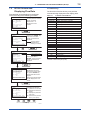
5.1
Display Configuration
Figure 5.1 shows the configuration of the
digitalYEWFLO display panel (if equipped).
1 Data Display
(Upper)
4 Unit Display
3 Alarm Display
2 Data Display
SET
(Lower)
4 Unit Display
SHIFT
INC
5 Setting Keys
F0501.ai
Figure 5.1
1
2
3
4
5
Display Configuration
Data Display(Upper) : flowrate data, setting data,
total data
temperature data (/MV)
Data Display(Lower) : total data, alarm data
temperature data (/MV)
Alarm Display
: alarm of a flow error and a
vibration error
Unit Display
: flowrate unit
Setting Keys
: These keys are used to
change flow rate data
displays and type of
setting data
IM 01F06A00-01EN
5-2
<5. BASIC OPERATING PROCEDURES>
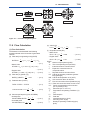
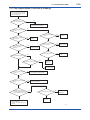
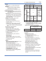
5.2
Display Contents
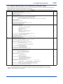
The display content items are classified in the following three items.
Table 5.1
Mode Name List
Mode (status) Name
Display Contents
Flow rate display mode
A mode in which instantaneous flow rates or totalized values are displayed.
Display content is usually selected either in display content selection mode or by setting
parameters via BRAIN communication.
Setting mode
In this mode, parameter contents are confirmed or data is updated using the setting section. The
mode is changed to this mode when “SET” key is pressed in normal mode.
Alarm number display mode
This mode is overlapped when an alarm is occurring in display mode. The alarm number
presentation to indicate alarm contents (about 2 sec) and the normal data display (about 4 sec ) are
repeated alternatively.
Mode represents that the system is in a state where the relevant setting or display is possible.
● Display Example
SET
SHIFT + SET
Flowrate Display Mode
UPPER
Flow rate
LOWER
Total rate
UPPER
Flow rate (%)
LOWER
Blank
Setting Mode
Error Mode
NORMAL
INDICATION
(4 sec)
Switching
of setting
number
SHIFT
This mode display can be selected
below.
• Upper display : Flow rate
• Lower display : Total rate or Blank
Alternately
ERROR INDICATION
(2 sec)
• When an alarm situation occurs,
this mode will replace the current
mode (flow rate or setting mode)
to show what type of alarm has
occurred.
• Read Section 6.5 “SelfDiagnostic (Error Code List)”
about the error descriptions and
error number.
• This mode is used to check parameter
content and rewrite data. This mode can
be called up from the flowrate display
mode by pressing the “SET” key.
• Setting item and setting number can be
changed when pressing “SHFT” key.
• This mode can be called up by pressing
“SET” key while pressing “SHIFT” key
when setting mode is displayed.
F0502.ai
IM 01F06A00-01EN
<5. BASIC OPERATING PROCEDURES>
5.3
5-3
Display Mode
The display mode is a mode in which instantaneous
flow rates or totalized flow are displayed. In display
mode, there are three display modes as shown in
Table 5.2.
Table 5.2
Display Mode
Name
Contents
Upper Lower
Display Display
% Display
(Flow rate)
Instantaneous % flow
rate is
displayed.
○
Engineering
Display Unit
Instantaneous flow rate
in an
engineering unit is
displayed.
○
Totalized
Display
Totalized flow displayed
without indicating the
decimal
point.
○
○
○
○
% Display
Instantaneous temperature
(Temperature) is displayed.
(*1)
In this case, “t” is displayed
simultaneously (Read
Figure 5.2).
Temperature
display(*1)
Temperature value is
displayed.
Blank
-----
(*1) Only for /MV.
○: Displayed ×: Not displayed
F0503.ai
Figure 5.2
% Display (Temperature)
Display mode can be changed using the BT200 or
the indicator setting section.
(1) For operation using BT200, perform changes
using the parameter item “ B30:UPPER DISP”
and “B31:LOWER DISP”.
(2) For operation using indicator, change B30
and B31 parameter item number to display an
appropriate display.
IMPORTANT
After setting a parameter, keep the power on for
at least 30 seconds.
If the power of flowmeter is turned off, a
parameter setting is released.
IM 01F06A00-01EN
5-4
<5. BASIC OPERATING PROCEDURES>
5.3.1 Changes to Engineering Display Unit from % Display
The display mode can be changed referring to Section 6.3 “Parameters List.”
Indication of %
display.
Indicate “ 01 ” of
engineering unit.
SET
SHIFT
SET
INC
SHIFT
INC
Press “ SET ” key.
Press “ SET ” key.
Enter the setting
mode.
Ensure the setting
data.
SET
SHIFT
SET
INC
SHIFT
INC
Press “ SHIFT ” key.
Press “ SET ” key.
Enter the parameter
item.
Finish the setting.
SET
SHIFT
SET
INC
SHIFT
INC
Press “ INC ” key any time.
Press “ SET ” and “ SHIFT ” key.
Indicate “ 30 ”.
Return to display
mode.
SET
SHIFT
SET
INC
SHIFT
INC
Press “ SET ” key.
Enter the data
input item.
SET
SHIFT
INC
IMPORTANT
After setting a parameter, keep the power on for
at least 30 seconds.
If the power of flowmeter is turned off, a
parameter setting is released.
Press “ INC ” key.
F0504.ai
IM 01F06A00-01EN
5-5
<5. BASIC OPERATING PROCEDURES>
5.3.2 Indicate the Total Rate in the Data Display(Lower)
The display mode can be changed referring to Section 6.3 “Parameters List.”
SET
SHIFT
Indication of
engineering unit
display.
Lower display is
“ Blank ”.
INC
Indicate “ 01 ” of
lower the display
item.
SET
SHIFT
INC
Press “ SET ” key.
Press “ SET ” key.
Enter to the setting
mode.
Ensure the setting
data.
SET
SHIFT
SET
INC
SHIFT
INC
Press “ SHIFT ” key.
Press “ SET ” key.
Enter to the
parameter item.
Finish the setting.
SET
SHIFT
SET
INC
SHIFT
INC
Press “ INC ” key any time.
Press “ SET ” and “ SHIFT ” key.
Indicate “ 31 ”.
Return to display
mode.
SET
SHIFT
SET
INC
SHIFT
INC
Press “ SET ” key.
Enter the data input
item.
SET
SHIFT
INC
IMPORTANT
After setting a parameter, keep the power on for
at least 30 seconds.
If the power of flowmeter is turned off, a
parameter setting is released.
Press “ INC ” key.
F0505.ai
IM 01F06A00-01EN
5-6
<5. BASIC OPERATING PROCEDURES>
5.4
Setting Mode
Flowrate Display Mode
The setting mode is used for checking parameters
and rewriting data. The following is an overview of
the setting mode.
SHIFT+SET
SET
Parameter Setting Mode
NOTE
Select Item
• Read Section 6.3 “Parameters List” and
Section 6.4 “Parameters Description” on how
to change setting.
SHIFT : Menu
SHIFT+SET
SET
INC
Item Number
: Inc. Menu / Item Number
Set Data
5.4.1 Display Configuration of Setting
Mode
Select Type
INC : Inc. Data Number
Simple parameter sheet
Numeric Value Setting Type
In this sheet, a setting flow chart and the parameter
list required to operate digitalYEWFLO is indicated.
Item number
Change item number using
“SHIFT” key and “INC”key.
SET
SHIFT : Move Cursor
INC
: Inc. Numeric Value
SHIFT or INC
Check Setting Data
SET
Fix Setting Data
F0507.ai
SET
SHIFT
INC
Data number
Change the data number
using “SHIFT” key and
“INC” key.
F0506.ai
Figure 5.3
Indicator Configuration and Parameter
Setting Procedure
• When completing setting, press “SHIFT” key
and “SET” key simultaneously. The mode
move to the “display mode”.
IMPORTANT
After setting a parameter, keep the power on for
at least 30 seconds.
If the power of flowmeter is turned off, a
parameter setting is released.
IM 01F06A00-01EN
5-7
<5. BASIC OPERATING PROCEDURES>
5.4.2 Data Setting Method
Input method of numeric data
Example 1: Change the span from 100m3/h to 150m3/h
The setting mode can be changed referring to Section 6.3 “Parameters List.”
Indication of % flow
rate.
Ensure the setting
data.
SET
SHIFT
SET
INC
SHIFT
INC
Press “ SET ” key.
Press “ SET ” key.
Enter to the setting
mode.
(Span number is
“ B10 ”)
Complete the Setting.
SET
SHIFT
SET
INC
SHIFT
INC
Press “ SET ” and “ SHIFT ” key.
Press “ SET ” key.
Enter to data number
item.
Return to display
mode.
SET
SHIFT
SET
INC
SHIFT
INC
Press “ SHIFT ” key any time.
Move the position to
input the data.
IMPORTANT
SET
SHIFT
INC
Press “ INC ” key any time.
After setting a parameter, keep the power on for
at least 30 seconds.
If the power of flowmeter is turned off, a
parameter setting is released.
Set “ 5 ” and indicate
“ 150m3/h ”.
SET
SHIFT
INC
Press “ SET ” key.
F0508.ai
IM 01F06A00-01EN
5-8
<5. BASIC OPERATING PROCEDURES>
Input method of selection items
Example 2: Change the pulse output to alarm output.
The setting mode can be changed referring to Section 6.3 “Parameters List.”
Indication of % unit.
Indicate “ 03 ” of
alarm output item.
SET
SHIFT
SET
INC
SHIFT
INC
Press “ SET ” key.
Press “ SET ” key.
Enter to the setting
mode.
Ensure the setting.
SET
SHIFT
SET
INC
SHIFT
INC
Press “ SHIFT ” key.
Press “ SET ” key.
Enter to the
parameter item.
Finish the parameter
setting.
SET
SHIFT
SET
INC
SHIFT
INC
Press “ INC ” key any time.
Press “ SET ” and “ SHIFT ” key.
Indicate “ 20 ”.
Return to display
mode.
SET
SHIFT
SET
INC
SHIFT
INC
Press “ SET ” key.
Enter to the data
input item.
SET
SHIFT
INC
IMPORTANT
After setting a parameter, keep the power on for
at least 30 seconds.
If the power of flowmeter is turned off, a
parameter setting is released.
Press “ INC ” key any time.
F0509.ai
IM 01F06A00-01EN
6-1
<6. PARAMETERS>
6.
6.1
PARAMETERS
digitalYEWFLO Parameters
6.3
Parameters List
The parameters are set before factory shipment.
Set the required parameter of changing fluid,
contact out and indication of display.
This section describes the parameter of
digitalYEWFLO.
• Contents of parameters list.
6.2
Item
Parameter item number.
Name
Parameter name.
R/W
(Read
and Write)
Indicates parameter attributes.
R : Display only (writing is not permitted).
W : Writing is permitted.
Data Range
Shows data setting ranges for numerical value
entry.
Shows data to be selected for data selection.
( ) in parentheses, data code is shown for the
display.
Item
Multi-Variable Type (/MV)
Parameters
Parameter item F is indicated when /MV is selected.
The parameters are set before factory shipment,
but it is necessary to set the analog output of
temperature, span of temperature output.
IMPORTANT
For the remote type, be sure to set the cable
length (F52) for remote type converter (DYA),
because of effect of the cable length.
Description
Unit
Engineering unit.
Remark
Remarks such as a description of the contents
are given.
Initial value
Indicates the initial set values.
Disp.
D : Display can set parameter.
U/D
L : Parameter can be set by UP LOAD and
DOWN LOAD.
(Check all parameters after setting by DOWN
LOAD.)
IM 01F06A00-01EN
6-2
<6. PARAMETERS>
(1) Item A : Indication
These items are for the indication of flowrate and total.
Item
Name
R/W
Data Range
Unit
Decimal
Point
Remark
A00
DISPLAY
A10
FLOW RATE (%)
R
0.0 to 110.0
%
1
A20
FLOW RATE
R
0.0 to 65535
FU+C40
0 to 5
Flow Rate (in engineering unit)
A30
TOTAL
R
0 to 999999 (*2)
FU
0 to 5
Totalized Value
%
1
Temperature Values (%)
D20
1
Temperature Values
Initial
Disp. U / D (*1)
Value
Menu A (Display)
Flow Rate
(Indicate only for /MV and B50 : TEMP)
A40
TEMP (%) (*1)
R
0.0 to 110.0
(Indicate only for /MV)
A41
TEMPERATURE (*1)
R
–999.9 to 999.9
A60
SELF CHECK
R
GOOD
ERROR
Self-diagnostic message
FU : Flow unit
/MV : Multi-Variable (Build-in Temperature Sensor) Type
(*1) : Available for 3.10 or greater version that can be checked in K50.
(*2) : There will be linked to the value of B45, it is displayed “E” shows multipiler 10.
(2) Item B : Easy Setting
These items are for the principal items to operate digitalYEWFLO.
A value in “( )” is the data corresponding to the indicator.
Item
Name
R/W
B00
B10
B15
B20
EASY SETUP
FLOW SPAN
DAMPING
CONTACT OUT
W
W
W
Data Range
Unit
Decimal
Point
0.00001 to 32000
FU + C40 0 to 5
0 to 99
sec
0
OFF
(0)
SCALED PULSE
(1)
UNSCALED PULSE
(2)
FREQUENCY
(3)
ALARM
(4)
FLOW SW(LOW:ON) (5)
FLOW SW(LOW:OFF) (6)
(Indicate and Set only for B20: SCALED PULSE, UNSCALED PULSE)
B21 PULSE RATE
W 0.00001 to 32000
FU / P
0 to 5
(Indicate and Set only for B20: FREQUENCY)
B22 FREQ AT 100%
W 0 to 10000
PPS
0
(Indicate and Set only for B20: FLOW SW (ON), FLOW SW (OFF))
B23 SET LEVEL
W 0.00001 to 32000
FU +C40 0 to 5
B30 UPPER DISP
W FLOW RATE (%)
(0)
FLOW RATE
(1)
TEMP (%)
(2)
B31 LOWER DISP
W BLANK
(0)
TOTAL
(1)
TEMP
(2)
B40 TOTAL START
W STOP
(0)
START
(1)
B45 TOTAL RATE
W 0.00001 to 32000
(0) FU / P
0 to 5
B47 TOTAL RESET
W NOT EXECUTE
(0)
EXECUTE
(1)
(Indicate and Set only for /MV)
B50 A / OUT SELECT
W
FLOW
TEMP
(Indicate and Set only for /MV and B50: TEMP)
B51 TEMP 0%
W -999.9 to 999.9
B52 TEMP 100%
W -999.9 to 999.9
B60 SELF CHECK
R GOOD
ERROR
(0)
(1)
Remark
Menu B
Flow Span
Damping Time
Contact Output Type
10
4
(0)
D
D
D
L
L
L
1.0 (*3)
D
L
Pulse Output Rate at sec /100% 1000
D
L
Flow Switch (Actual Flow rate)
Selection of Upper Display
0
(0) (*3)
D
D
L
L
(only for /MV)
Selection of Lower Display
(0)
D
L
(only for /MV)
Start / Stop of Totalizer
(0)
D
L
1.0 (*3)
(0)
D
D
L
L
(0)
D
L
D
D
L
L
Pulse Output Rate
Total Rate
Totalizer Reset
Selection of Analog Output
D20
D20
1
1
Initial
Disp. U / D (*1)
Value
Set Temperature Value at 0%
-40
Set Temperature Value at 100% 250 (*2)
Self-diagnostic Message
FU : Flow unit
(*1) : Available for 3.10 or greater version that can be checked in K50.
(*2) : If 7.00 or less version that can be checked in K50, Initial Value is 260.
IM 01F06A00-01EN
6-3
<6. PARAMETERS>
(3) Item C : BASIC SETUP
These items are for the basic parameters with setting before shipment.
The parameters, C20 to C50, are not indicated when option code “/MV” is selected and parameter item is
selected in F10 except “Monitor only” or “Not use”.
A value in “( )” is the data corresponding to the indicator.
Item
Name
R/W
Data Range
Unit
Decimal
Point
Remark
Initial
Value
Disp. U / D (*1)
C00 BASIC SETUP
C10 TAG NO.
W
16 characters
C20 FLUID
W
LIQUID:Volume
GAS/STEAM:Volume
LIQUID:Mass
GAS/STEAM:Mass
GAS:STD/Normal
Tag Number
(0)
(1)
(2)
(3)
(4)
(*2)
Selection of FLUID type
(0) (*2)
D
L
Selection of Flow Units for
Flow Rate
(0)(*2)
D
L
Selection of Density Unit
(0)(*2)
D
L
1024(*2)
D
L
(0) (*2)
D
L
(Indicate and Set only for C20 : LIQUID : Volume, GAS / STEAM: Volume)
C22 VOLUME UNIT
W
m3
k m3
l
cf
m cf
k cf
USgal
k USgal
UKgal
k UKgal
bbl
m bbl
k bbl
(0)
(1)
(2)
(3)
(4)
(5)
(6)
(7)
(8)
(9)
(10)
(11)
(12)
(Indicate and Set only for C20 : LIQUID : Mass, GAS / STEAM : Mass)
C25 DENSITY UNIT
W
kg/m3
lb/cf
lb/USgal
lb/UKgal
C26 DENSITY f
W
0.00001 to 32000
C27 MASS UNIT
W
kg
t
lb
k lb
(0)
(1)
(2)
(3)
C25
(0)
(1)
(2)
(3)
0 to 5
Operating Density
(Manual Setting Value)
Selection of Mass Flow Unit
IM 01F06A00-01EN
6-4
<6. PARAMETERS>
Item
Name
R/W
Data Range
Unit
Decimal
Point
Remark
Initial
Value
Selection of Temperature Unit
(0) (*2)
D
L
Disp. U / D (*1)
(Indicate and Set only for C20 : GAS : STD / Normal)
C30 TEMP UNIT
W
deg C
deg F
C31 TEMP f
W
-999.9 to 999.9
C30
1
Operating Temperature
(Manual Setting Value)
15.0 (*2)
D
L
C32 TEMP b
W
-999.9 to 999.9
C30
1
Standard / Normal
Temperature
15.0 (*2)
D
L
C33 PRESS UNIT
W
MPa abs
kPa abs
bar abs
kg/cm2 a
psia
(0) (*2)
D
L
C34 PRESS f
W
0.00001 to 32000
C33
0 to 5
Absolute Pressure at
Operating Condition
(Manual Setting Value)
0.1013 (*2)
D
L
C35 PRESS b
W
0.00001 to 32000
C33
0 to 5
Absolute Pressure at Standard 0.1013 (*2)
Condition
D
L
C36 DEVIATION
W
0.001 to 10.0
Deviation Factor
1.0 (*2)
D
L
C37 STD/NOR UNIT
W
Nm
k Nm3
M Nm3
Nl
Sm3
k Sm3
M Sm3
Sl
scf
k scf
M scf
(0)
(1)
(2)
(3)
(4)
(5)
(6)
(7)
(8)
(9)
(10)
Selection of Volumetric Unit at
Normal
Condition
N: Normal
S: Standard
(0) (*2)
D
L
C40 TIME UNIT
W
/s
/m
/h
/d
(0)
(1)
(2)
(3)
Selection of Time Unit
(2) (*2)
D
L
C45 FLOW SPAN
W
0.00001 to 32000
Flow Span
10 (*2)
D
L
C50 DAMPING
W
0 to 99
4
D
L
C60 SELF CHECK
R
GOOD
ERROR
3
(0)
(1)
(0)
(1)
(2)
(3)
(4)
Selection of Pressure Unit
3
FU+C40
0 to 5
sec
0
Damping Time
Self-diagnostic Message
FU : Flow unit
(*1) : Available for 3.10 or greater version that can be checked in K50.
(*2) : If specified when ordering, it is set to the specified contents.
IM 01F06A00-01EN
6-5
<6. PARAMETERS>
(4) Item D : Additional Setup
These items are for Auxiliary Setup.
A value in “( )” is the data corresponding to the indicator.
Item
Name
R/W
Data Range
Unit
Decimal
Point
FU + C40
0 to 5
D00 AUX. SETUP
Remark
Initial
Disp. U / D (*1)
Value
Menu D (Additinal Setup)
D10 LOW CUT
W
* to 32000
D20 TEMP UNIT
W
deg C
deg F
D21 TEMP f
W
-999.9 to 999.9
D25 DENSITY UNIT
W
kg/m3
lb/cf
lb/USgal
lb/UKgal
D26 DENSITY f
W
0.00001 to 32000
D30 OUT LIMIT (H)
W
100.0 to 110.0
D35 BURN OUT
R
High
Low
(0)
(1)
No
Yes
Special
(0)
(1)
(2)
D40 SPECIAL UNIT
(0)
(1)
D20
1
(0)
(1)
(2)
(3)
Low Cut Flow Rate
*Minimum Flow Rate / 2
0.47
D
Selection of Temperature Unit
(0) (*2)
D
L
15.0 (*2)
D
L
(0) (*2)
D
L
1024 (*2)
D
L
110.0
D
L
Output Direction at Burn Out
(0)
D
L
Selection of change for Special Flow
Unit
(0)
D
L
Operating Temperature (Manual
Setting Value)
Selection of Density Unit
D25
0 to 5
%
1
Operating Density (Manual Setting
Value)
Upper Limit Value
(Indicate and Set only for D40: Yes, Special)
D41 BASE UNIT
R
m3
k m3
l
cf
m cf
k cf
USgal
kUSgal
UKgal
kUKgal
bbl
m bbl
k bbl
kg
t
lb
k lb
Nm3
k Nm3
M Nm3
NI
Sm3
k Sm3
M Sm3
SI
scf
k scf
M scf
D42 USER’S UNIT
W
8 characters
D43 CONV
FACTOR
W
0.00001 to 32000
D60 SELF CHECK
R
GOOD
ERROR
(0)
(1)
(2)
(3)
(4)
(5)
(6)
(7)
(8)
(9)
(10)
(11)
(12)
(13)
(14)
(15)
(16)
(17)
(18)
(19)
(20)
(21)
(22)
(23)
(24)
(25)
(26)
(27)
Basic unit for conversion to Special
Unit
N: Normal
S: Standard
D
L
User’s Unit (*3)
0 to 5
Conversion Factor
1.0
D
L
Self-diagnostic Message
FU : Flow unit
(*1) : Available for 3.10 or greater version that can be checked in K50.
(*2) : If specified when ordering, it is set to the specified contents.
(*3) : Available characters are same as C10.
Read Section 6.4 “Parameters Description.”
IM 01F06A00-01EN
6-6
<6. PARAMETERS>
(5) Item E : Detector Setup
These items are for detector that has been already set before.
A value in “( )” is the data corresponding to the indicator.
Item
Name
R/W
Data Range
Unit
Decimal
Point
E00 METER SETUP
Remark
Initial
Disp. U / D (*1)
Value
Menu E (Detector setup)
(1) (*2)
D
L
Selection of Body Type
(0)
D
L
(0)
(1)
(2)
Selection of Sensor Type
(0)
D
L
(0)
(1)
(2)
Selection of K-factor Unit
(0)
D
L
K-factor value of 15 deg C
68.6
D
E10 NOMINAL SIZE
W
15mm
25mm
40mm
50mm
80mm
100mm
150mm
200mm
250mm
300mm
400mm
(0)
(1)
(2)
(3)
(4)
(5)
(6)
(7)
(8)
(9)
(10)
Selection of Nominal Size
E20 BODY TYPE
W
Standard
High Pressure
Low Flow Unit (1)
Low Flow Unit (2)
(0)
(1)
(2)
(3)
E30 SENSOR TYPE
W
Standard
High Temperature
Low Temperature
E40 K-FACT UNIT
W
P/l
P/USgal
P/UKgal
E41 K-FACTOR
W
0.00001 to 32000
E50 DETECTOR No.
W
16 characters
E40
0 to 5
Detector Number
E60 SELF CHECK
R
GOOD
ERROR
Self-diagnostic Message
FU : Flow unit
(*1) : Available for 3.10 or greater version that can be checked in K50.
(*2) : If specified when ordering, it is set to the specified contents.
IM 01F06A00-01EN
6-7
<6. PARAMETERS>
(6) Item F: Thermometer (Only for Multi-Variable Type)
These items is for thermometer setting when.
A Value in “( )” is the data corresponding to the indicator.
Item
Name
R/W
Data Range
Unit
Decimal
Point
F00 THERMOMETER
F10 Function
Remark
Initial
Disp. U / D (*1)
Value
Menu F (Thermometer function)
W
Monitor only
Saturated Steam
Superheat Steam
GAS: STD/Normal
LIQUID: Mass
Not use
(0)
(1)
(2)
(3)
(4)
(5)
Select thermometer function.
(Move to F40 when “Monitor only” is
selected)
(Move to F60 when “Not Use” is
selected)
(0)
D
L
Selection of mass flow rate unit
(0)
D
L
Selection of pressure unit
(0)
D
L
(Indicate and Set only for F10: Saturated Steam)
F12 MASS UNIT
W
kg
t
Ib
k Ib
(0)
(1)
(2)
(3)
(Indicate and Set only for F10: Superheat Steam)
F14 PRSS UNIT
W
MPa abs
kPa abs
bar abs
kg/cm2 a
psia
F15 PRESS f
W
0.00001 to 32000
F16 MASS UNIT
W
kg
t
Ib
k Ib
(0)
(1)
(2)
(3)
(4)
F14
0 to 5 Absolute pressure at operating
condition(Manual setting vaiue)
(0)
(1)
(2)
(3)
0.1013
Selection of mass flow rate unit
(0)
D
L
Selection of temperature unit
(0)
D
L
Standard/Normal temperature
15.0
D
L
(0)
D
L
(Indicate and Set only for F10: GAS: STD/Normal)
F18 TEMP UNIT
W
deg C
deg F
(0)
(1)
F19 TEMP b
W
-999.9 to 999.9
F20 PRESS UNIT
W
MPa abs
kPa abs
bar abs
kg/cm2 a
psia
F21 PRESS f
W
0.00001 to 32000
F20
0 to 5 Absolute pressure at operating
condition(Manual setting value)
0.1013
D
L
F22 PRESS b
W
0.00001 to 32000
F20
0 to 5 Absolute pressure at Standard
condition
0.1013
D
L
F23 DEVIATION
W
0.001 to 10.000
Deviation factor
1.0
D
L
F24 STD/NOR UNIT
W
Nm
k Nm3
M Nm3
NI
Sm3
k Sm3
M Sm3
SI
scf
k scf
M scf
Selection of volumetric unit at normal
condition
N: Normal
S: Standard
(0)
D
L
3
F18
1
Selection of temperture unit
(0)
(1)
(2)
(3)
(4)
3
(0)
(1)
(2)
(3)
(4)
(5)
(6)
(7)
(8)
(9)
(10)
IM 01F06A00-01EN
6-8
<6. PARAMETERS>
Item
Name
R/W
Data Range
Unit
Decimal
Point
Remark
Initial
Disp. U / D (*1)
Value
(Indicate and Set only for F10: LIQUID: Mass)
F26 DENSITY UNIT
W
kg/m3
Ib/cf
Ib/USgal
Ib/UKgal
F27 DENSITY b
W
0.00001 to 32000
F28 TEMP UNIT
W
deg C
deg F
F29 TEMP b
W
-999.9 to 999.9
(0)
(1)
(2)
(3)
Selection of density unit
F26
(0)
D
L
0 to 5 Density of standard condition
1.0
D
L
Selection of temperature unit
(0)
D
L
15.0
D
L
(0)
(1)
F28
1
Temperature of standard condition
F30 1st coef
W
-32000 to 32000
1/F28
0 to 5 1st temperature coefficient
1.0
D
L
F31 2nd coef
W
-32000 to 32000
1/F282
0 to 5 2nd temperature coefficient
1.0
D
L
F32 MASS UNIT
W
kg
t
Ib
k Ib
(0)
(1)
(2)
(3)
Selection of mass flow rate unit
(0)
D
L
F35 TIME UNIT
W
/s
/m
/h
/d
(0)
(1)
(2)
(3)
Selection of time unit
1
D
L
F40 FLOW SPAN
W
0.00001 to 32000
0.5
D
L
F45 DAMPING
W
0 to 99
FU+35
sec
0 to 5 Flow span
0
Damping
4
D
L
F50 TEMP DAMPING
W
0 to 99
sec
0
Damping for temperture output
4
D
L
F52 CABLE LENGTH
W
0 to 30
m
0
Cable length for signal cable (0m in
case of integral version)
0
D
L
F55 A/OUT SELECT
W
FLOW
TEMP
(0)
D
L
L
(0)
(1)
Selection of analog output
(Indicate and Set only for F55: TEMP)
F56 TEMP 0%
W
-999.9 to 999.9
D20
1
Temperture value at 0%
F57 TEMP 100%
W
-999.9 to 999.9
D20
1
Temperture value at 100%
F58 TEMP ERR OUT
W
0%
OUT LIMIT(H)
TEMP f
F60 SELF CHECK
R
GOOD
ERROR
(0)
(1)
(2)
Selection of themometer error output
when “F55: TEMP” is selected (A
value of OUT LIMIT(H) depend on
D30)
-40
D
250 (*2)
D
L
1
D
L
Self-diagnostic Message
(*1) : Available for 3.10 or greater version that can be checked in K50.
(*2) : If 7.00 or less version that can be checked in K50, Initial Value is 260.
IM 01F06A00-01EN
6-9
<6. PARAMETERS>
(7) Item H : Adjust.
These items are for setting of adjustment.
A value in “( )” is the data corresponding to the indicator.
Item
Name
Unit
Decimal
Point
-1.00 to 1.00
%
2
%
R/W
Data Range
H00 ADJUST
H10 TRIM 4mA
Initial
Disp. U / D (*1)
Value
Remark
Menu H (Adjust)
W
H11 TRIM 20mA
W
-1.00 to 1.00
H20 USER ADJUST
W
0.00001 to 32000
H25 REYNOLDS ADJ
W
NOT ACTIVE
ACTIVE
Trimming 4mA
2
0 to 5
(0)
(1)
0.0
D
Trimming 20mA
0.0
D
User Adjust
1.0
D
Reynolds Coefficient
(0)
D
(Indicate and Set only for H25: ACTIVE)
H26 DENSITY f
W
0.00001 to 32000
D25
0 to 5
Density at operating condition
1024
D
H27 VISCOSITY
W
0.00001 to 32000
mPa.s
0 to 5
Viscosity factor
1.0
D
H30 EXPANSION FA
W
NOT ACTIVE
ACTIVE
(0)
(1)
Expansion correction for
compressible Gas
(0)
D
H40 FLOW ADJUST
W
NOT ACTIVE
ACTIVE
(0)
(1)
Instrumental Error Adjust
(0)
D
(Indicator and Set only for H40: ACTIVE)
H41 FREQUENCY 1
W
0 to 32000
Hz
0 to 5
H42 DATA 1
W
-50.00 to 50.00
%
2
H43 FREQUENCY 2
W
0 to 32000
Hz
0 to 5
H44 DATA 2
W
-50.00 to 50.00
%
2
H45 FREQUENCY 3
W
0 to 32000
Hz
0 to 5
H46 DATA 3
W
-50.00 to 50.00
%
2
H47 FREQUENCY 4
W
0 to 32000
Hz
0 to 5
H48 DATA 4
W
-50.00 to 50.00
%
2
H49 FREQUENCY 5
W
0 to 32000
Hz
0 to 5
H50 DATA 5
W
-50.00 to 50.00
%
2
H60 SELF CHECK
R
GOOD
ERROR
First break-point frequency
(f1)
0.0
D
First correcting value
(d1)
0.0
D
Second break-point frequency (f2)
0.0
D
Second correcting value
(d2)
0.0
D
Third break-point frequency
(f3)
0.0
D
Third correcting value
(d3)
0.0
D
Fourth break-point frequency
(f4)
0.0
D
Fourth correcting value
(d4)
0.0
D
Fifth break-point frequency
(f5)
0.0
D
Fifth correcting value
(d5)
0.0
D
Self-diagnostic Message
(*1) : Available for 3.10 or greater version that can be checked in K50.
(8) Item J : Test
These items are for test of output.
A value in “( )” is the data corresponding to the indicator.
Item
Name
R/W
Data Range
Unit
Decimal
Point
J00 TEST
Remark
Initial
Disp. U / D (*1)
Value
Menu J (Test)
J10 OUT ANALOG
W
0.0 to 110.0
%
1
Current Output
0.0
D
J20 OUT PULSE
W
0 to 10000
PPS
0
Pulse Output
0
D
J30 OUT STATUS
W
OFF
ON
(0)
(1)
Status Output
(0)
D
J40 (*2) RELEASE TIME
W
10min
30min
60min
3h
6h
12h
(0)
(1)
(2)
(3)
(4)
(5)
Test auto release time
0
D
J60 SELF CHECK
R
GOOD
ERROR
Self-diagnostic Message
(*1) : Available for 3.10 or greater version that can be checked in K50.
(*2) : Available for 7.00 or greater version that can be checked in K50.
IM 01F06A00-01EN
6-10
<6. PARAMETERS>
(9) Item K : Maintenance
These items are for maintenance.
Item
Name
R/W
Data Range
Unit
Decimal
Point
K00 MAINTENANCE
Remark
Initial
Disp. U / D (*1)
Value
Menu K (Maintenance)
K10 TLA
W
0.1 to 20.0
1
Trigger Level Adjust
1.0
D
K20 SIGNAL LEVEL
W
0.1 to 20.0
1
Signal Level
1.0
D
K25 N.B. MODE
W
AUTO
(0)
MANUAL
(1)
TUNING AT ZERO (2)
Selection of Noise balance Mode
(0)
D
K26 NOISE RATIO
R / W 0.00 to 2.00
2
0 to 10000
Hz
0 to 5
Ratio of noise balance
D
Output test by setting simulated
frequency.(*2)
D
K28 SET VORTEX F
W
K30 VELOCITY
R
m/s
2
Velocity
D
K32 SPAN V
R
Hz
2
Span velocity
D
K34 VORTEX FREQ.
R
Hz
K36 SPAN F
R
0 to 5
Vortex frequency
D
0 to 5
Span frequency
D
(Indicate only for F10: Saturated Steam, Superheat Steam, LIQUID: Mass)(*1)
K38 DENSITY
R
K40 ERROR RECORD
R
K45 H VIBRATION
W
0.00001 to 32000
D25
0 to 5
Density value (Calculated by
Thermometer)
D
Error Records
0%
NO ACTION
K50 SOFTWARE REV
R
0.01 to 99.99
K60 SELF CHECK
R
GOOD
ERROR
(0)
(1)
Selection of Output Function when (1) (*3)
“High Vibration” error is indicated.
2
Software Revision Number
Self-diagnostic Message
/MV : Multi-Variable (Build-in Temperature Sensor) Type
(*1) : Available for 3.10 or greater version that can be checked in K50.
(*2) : Available for 5.10 or greater version that can be checked in K50.
(*3) : If 7.00 or less version that can be checked in K50, Initial Value is 0.
(10) Item M : Memo
These items are for Memorandum.
Item
Name
R/W
Data Range
Unit
Decimal
Point
M00 MEMO
Remark
Initial
Disp. U / D (*1)
Value
Menu M (Memo)
M10 MEMO 1
W
16 characters
W
Memorandum 1 (*2)
M20 MEMO 2
W
16 characters
W
Memorandum 2 (*2)
M30 MEMO 3
W
16 characters
W
Memorandum 3 (*2)
M60 SELF CHECK
R
GOOD
ERROR
R
Self-diagnostic Message
(*1) : Available for 3.10 or greater version that can be checked in K50.
(*2) : Available characters are same as C10.
Read Section 6.4 “Parameters Description.”
IM 01F06A00-01EN
6-11
<6. PARAMETERS>
6.4
Parameters Description
(1) Item A : Display
These items are for the indication of flowrate and
total.
[A10:FLOW RATE(%)] Flow rate
(2) Item B : Easy Setting
These items are for the Principal items to operate
digitalYEWFLO.
A value in “( )” is the data corresponding to indicator.
[B10:FLOW SPAN] Flowrate span
Set the required span with a numerical.
Flowrate is displayed by “%” to span value.
[A20:FLOW RATE] Flow rate (Engineering
unit)
Flowrate is displayed by engineering unit.
[A30:TOTAL] Total value
Total value of flowrate is displayed
Note: There will be linked to the value of B45
TOTAL RATE, it is displayed “E” shows
multipiler 10.
NOTE
The range of measurable flow velocity is as
described in Table 13.6
[B15:DAMPING] Damping time constant
Set damping time constant values from 0s to 99sec.
[B20:CONTACT OUT] Contact output
Example
B45
A30
10000 (= 10 )
4
Item
999999E4
10 (= 10 )
999999E1
0.00001
9.99999
1
Select contact output.
The following item should be done in case
of which Option code /MV is selected and
analog output is “Temperature”.
[A40:TEMP(%)] Temperature value
The measured temperature value is displayed by
“%” to span value of temperature.
The following item should be done in case
of which Option code /MV is selected.
[A41:TEMPERATURE] Temperature value
The measured temperature value is displayed by
engineering unit.
Description
OFF
(0)
------------------------
SCALED PULSE
(1) Scaled pulse output: Read “B21”
UNSCALED PULSE
(2) Unscaled pulse output: Read “B21”
FREQUENCY
(3) Frequency output: Read “B22”
ALARM
(4) Alarm output: The status goes
from close to open (OFF) during
alarming.
Read Section 6.5 “Self-Diagnostic
(Error Code List)”.
FLOW SW (LOW:ON)
(5) Status output: Read “B23”
FLOW SW (LOW:OFF)
(6) Status output: Read “B23”
[B21:PULSE RATE] Pulse output rate
Set output rate in a selection of SCALED PULSE or
UNSCALED PULSE.
SCALED PULSE OUTPUT:
When SCALED PULSE is selected in B20, set
flowrate per one pulse output. Rate unit is linking to
the flow unit.
UNSCALED PULSE OUTPUT:
When UNSCALED PULSE is selected in B20, it
outputs the pulse calculated by following formula.
The formula for output pulse number is as follows.
Output pulse number per one second = vortex
number per one second / PULSE RATE set
number.
Read Subsection 10.1.5 “Setting of Pulse Output
(Scaling)”.
IM 01F06A00-01EN
6-12
<6. PARAMETERS>
[B22:FREQ AT 100%] Pulse numbers of
100% at one second
[B47:TOTAL RESET] Reset the totalizer
Set pulse number at 100% for one second when
“FREQUENCY” in B20 is selected.
Pulse numbers (PPS)
When totalizer reset function is executed, the total
display and communication parameter are reset.
The following items should be done in case
of which Option code “/MV” is selected.
[B50 A/OUT SELECT] Analog Output select
T=1s
F0601.ai
Select the analog output select from flow rate or
temperature.
When changing the analog output, UPPER
DISPLAY can be changed shown as below
automatically.
B50 : A/OUT SELECT
UPPER DISPLAY
[B23:SET LEVEL] Level of flow switch
“TEMP” TO “FLOW”
FLOW (%)
Set level of flow switch when “FLOW SW” in B20 is
selected. The contact output is sent out when the
flowrate is less than the set comparison level.
“FLOW” TO “TEMP”
TEMP (%)
(“B30 : UPPER DISPLAY” is “FLOW RATE”, it can not be
changed.)
The following item should be done in case
of which B50 is “TEMP”
Output
(%)
Setting Value
10% Hysteresis
[B51 TEMP 0%] Temperature value of 0%
output
Set temperature value of 0% output.
[B52 TEMP 100%] Temperature value of
100% output
Contact Output ON : FLOW SW (LOW : ON)
Set temperature value of 100% output.
Contact Output OFF : FLOW SW (LOW : OFF)
F0602.ai
[B30:UPPER DISP] Upper indicator display
Select upper display, Flow rate (%) (0), Flowrate
(1), TEMP(%)(2). “TEMP(%)” can be selected
when Option Code /MV.
[B31:LOWER DISP] Lower indicator display
Select lower indicator display, “BLANK (0), TOTAL
(1), TEMP(2). When “BLANK” in B31 is selected,
indicator is blank. “TEMP” can be selected when
Option Code /MV.
[B40:TOTAL START]
Select the START/STOP of totalizer from “STOP
(0), START (1).”
[B45:TOTAL RATE] Total rate of the totalizer
Set the total rate of the totalizer.
IM 01F06A00-01EN
6-13
<6. PARAMETERS>
(3) Item C : BASIC SETUP
[C26:DENSITY f] Density at normal
operation conditions
These items are for the basic parameters with
setting before shipment.
The parameters which are set in B are not
necessary to set in C.
A value in “( )” is the data corresponding to
indicator.
Set the density value of the fluid at operating
condition for mass flow unit.
[C27:MASS UNIT] Mass flowrate unit
The parameters, C20 to C50, are not
indicated when option code “/MV” is
selected and parameter item is selected in
F10 except “Monitor only” or “Not Use”.
[C10: TAG NO] Tag. No
ABCDEFGHIJKLMNOPQRSTUVWXYZa
bcdefghijklmnopqrstuvwxyz01234567
8 9 . SPACE / - , + * ) ( ’ & % $ # “ !
F0603.ai
[C30:TEMP UNIT] Fluid temperature unit at
operating conditions
[C31:TEMP f] Fluid temperature at
operating conditions
Set fluid temperature at operating condition.
The following items should be done in case
of which “C20” is “GAS/STD : Normal”.
[C32:TEMP b] Fluid temperature at
standard/normal conditions
[C20:FLUID] Flowrate unit
Set the flowrate unit below.
Item
The following item should be done in case
of which “C20” is “GAS/STEAM : Volume”.
Select temperature unit at operating condition from
“degC (0), degF (1)”.
Set Tag. No. (16 characters)
Available characters are as follows.
LIQUID : Volume
Select the mass flowrate unit from kg(0), t(1), lb(2),
k lb(3).
Description
(0) Volumetric flow of Iiquid measuring
GAS/STEAM : Volume (1) Volumetric flow of gas or steam
measuring
LIQUID : Mass
(2) Mass flow of liquid measuring
GAS/STEAM : Mass
(3) Mass flow of gas or steam
measuring
GAS : STD/Normal
(4) Volumetric flow at Standard
condition
Set the values of Fluid temperature at standard
condition.
[C33:PRESS UNIT] Pressure unit
Select the unit of pressure.
BRAIN
MPa abs
kPa abs
bar abs
kg/cm2 a
psia
HART
(0)
(1)
(2)
(3)
(4)
MPa abs
kPa abs
kg/cm2 a
bar abs
psia
(0)
(1)
(2)
(3)
(4)
The following items should be done in case
of which “C20” is “LIQUID : Volume” or
“GAS/STEAM : Volume”.
[C34:PRESS f] Absolute pressure at
operating conditions
[C22:VOLUME UNIT] Volumetric unit
Set the absolute pressure at operating condition.
Select the unit of volumetric flow from m3(0),
k m3(1), l(2), cf(3), m cf(4), k cf(5), USgal(6),
k USgal(7), UKgal(8), k UKgal(9), bbl(10),
m bbl(11), k bbl(12).
[C35:PRESS b] Absolute pressure at
standard/normal condition
The following items should be done in case
of which “C20” is “LIQUID: Mass” or “GAS/
STEAM : Mass”
Set deviation factor.
[C25:DENSITY UNIT] Density Unit of Flow
measurement
Select volumetric unit at normal condition from
Nm3(0), k Nm3(1), M Nm3(2), Nl(3), Sm3(4),
k Sm3(5), M Sm3(6), Sl(7), scf(8), k scf(9), M scf(10).
N: Normal
S: Standard
Select the unit of density from kg/m3(0), lb(1), lb/
USgal(2), lb/UKgal(3).
Set the absolute pressure at normal condition.
[C36:DEVIATION] Deviation factor
[C37:STD/NOR UNIT] Volumetric unit at
normal conditions
IM 01F06A00-01EN
6-14
<6. PARAMETERS>
[C40:TIME UNIT] TIME UNIT
Select time unit from “/s(0), /m(1), /h(2), /d(3)”
[D30:OUT LIMIT] Limit value of output and
indication
[C45:FLOW SPAN] Flowrate span
Set limit value of output from 100.0% to 110.0%
Set the required span with a numerical value.
[D35:BURN OUT] Indication of the output
direction at burn out
[C50:DAMPING] Damping time constant
Set damping time constant values from 0 to 99s.
(4) Item D (AUX. SETUP)
These items are for Auxiliary setup.
A value in “( )” is the data corresponding to indicator.
[D10:LOW CUT] Low-cut flowrate
NOTE
For D10 setting, be sure to set “NOMINAL SIZE”
in E10 firstly.
Set to noise elimination or zero flow in the low
flowrate (or low frequency) range. The settable
range for low cut flowrate is more than halfminimum flowrate.
NOTE
In case that Reynolds adjustment (H25), Gas
expansion correction (H30) or select a break
point correction (H40) is necessary to set,
D10: LOW CUT must be set after the items
for compensations (H25, H30, H40) are set to
“ACTIVE”.
[D20:TEMP UNIT] Fluid temperature unit at
operating conditions
Select temperature unit at operating condition from
deg C (0), deg F (1).
This is indication of the output direction at burn out.
Read Subsection 10.1.6 “Setting of Burnout Switch”
when the output direction can be changed.
[D40:SPECIAL UNIT] Change to special
flowrate unit
No(0) : Off the function
Yes(1) : Convert the flow unit for USER’S UNIT
The factor to convert the flow unit comes
from D43. The time unit comes from C40 or
F35.
Special(2) : Convert the flow unit and time unit for
the USER’S UNIT.
The factor to convert the flow unit and
time unit comes from D43.
[D41:BASE UNIT] Indication of the base
flowrate unit
Indication of the basic flowrate unit when item D40
is “Yes(1)” or “Special(2)”.
[D42:USER'S UNIT] Free unit for users
Set in up to 8 alphanumeric characters when item
D40 is “Yes(1)” or “Special(2)”.
The character and sign which can be set up are the
same as C10.
[D43:CONV FACTOR] Conversion factor
Set the conversion factor when item D40 is “Yes(1)”
or “Special(2)”.
Set the conversion factor which is for both flow unit
and time unit in case of “Special(2)”.
[D21:TEMP f] Fluid temperature at
operating conditions
Set fluid temperature at operating condition.
[D25:DENSITY UNIT] Density Unit of Flow
measurement
Select the unit of density from kg/m3(0), lb/cf(1), lb/
USgal(2), lb/UKgal(3).
[D26:DENSITY f] Density at normal
operation conditions
Set the density value of the fluid at operating
condition for mass flow unit
IM 01F06A00-01EN
6-15
<6. PARAMETERS>
(5) Item E (METER SETUP)
These items are for detector set up that has already
been set before shipment.
A value in “( )” is the data corresponding to indicator.
[E10:NOMINAL SIZE] Nominal size of the
detector
Select the nominal size of the flowmeter, from
15mm(0), 25mm(1), 40mm(2), 50mm(3), 80mm(4),
100mm(5), 150mm(6), 200mm(7), 250mm(8),
300mm(9), or 400mm(10).
[E20:BODY TYPE] Body type for the
detector
Select body type for detector from standard or high
pressure.
Standard
(0) : Standard type
High Pressure
(1) : High Pressure type
(TOKUCHU)
Low Flow Unit (1) (2) : Reduced Bore type
(option code: /R1)
Low Flow Unit (2) (3) : Reduced Bore type
(option code: /R2)
NOTE
Parameter setting for the Reduced Bore type,
Select Low Flow Unit (1) or (2) and set. Set
nominal size of the model code to E10:
NOMINAL SIZE.
[E30:SENSOR TYPE] Sensor type for the
detector
Select sensor type for the detector from standard,
/HT, or /LT.
Standard
(0) : Standard type
High Temperature (1) : High Process Temperature
Version
Low Temperature (2) : Cryogenic Version
[E40:K-FACTOR UNIT] K-factor unit
Select this unit from p/l, p/USgal, p/UKgal.
IMPORTANT
K-FACTOR is the eigenvalue of each detector.
Please keep the factory preset value.
NEVER REWRITE IT.
(Unless the replacement of the remote type
detector.)
[E41:K-FACTOR] K-factor
The flowmeter name plate includes a K-factor (KM)
at 15°C for the combined detector.
[E50:DETECTOR NO.] Detector number of
flowmeter
Set the serial number using 16 alphanumeric
characters of the detector combined converter.
(6) ltem F (Thermometer)
These items are for setting of thermometer and
available when build in thermometer type (Option
code: /MV).
[F10: Function] Thermometer function
Select the thermometer function.
Monitor only (0):
Only temperature
measurement.
Saturated Steam (1): Mass Flow rate is calculated
from density values by
temperature measurement
using saturated steam table.
Superheat Steam (2): Mass Flow rate is calculated
from density values by
temperature measured by
using steam table. In order
to measure superheat
steam. It is necessary to
make constant pressure
value.
GAS: STD/Normal (3): Volumetric flow rate
at standard condition
is calculated by using
Pressure- Temperature
correction. It is necessary
to male constant pressure
value.
LIQUID: Mass (4):
Mass flow rate is calculated
by using the density
change values depend
on temperature values by
which the secondary order
function is used.
The following item should be done in case
of which F10 is Saturated steam
[F12 MASS UNlT] Mass flow unit
Select mass rate unit from kg(0), t(1), lb(2), k lb(3).
The following items should be done in case
of which F10 is Superheat steam
[F14 PRESS UNIT] Pressure unit
Select pressure unit from MPa abs(0), kPa abs(1),
bar abs(2), kg/cm2 a(3), psia(4).
[F15 PRESS f] Pressure value
Set absolute pressure values at operating condition.
IM 01F06A00-01EN
6-16
<6. PARAMETERS>
[F16 MASS UNIT] Mass flow unit
[F32 MASS UNIT] Mass unit
Select mass flow unit from kg(0), t(1), lb(2), k lb(3).
Select mass flow rate unit from kg(0), t(1), lb(2), k
lb(3).
The following items should be done in case
of which F10 is GAS: STD/Normal
[F35 TIME UNIT] Time unit
[F18 TEMP UNIT] Temperature unit
Select time unit from /s(0), /m(1), /h(2), /d(3).
Select temperature unit from deg C(0), deg F (1).
[F40 FLOW SPAN] Flow span
[F19 TEMP b] Temperature b
Set span flow rate, 0 to 32000.
Set temperature value at normal/standard
condition.
[F45 DAMPING] Flow damping
[F20 PRESS UNIT] Pressure unit
[F50 TEMP DAMPING] Temperature
damping
Select pressure unit from MPa abs(0), kPa abs(1),
bar abs(2), kg/cm2 a(3), psia(4).
[F21 PRESS f] Pressure value f
Set absolute pressure values at operating condition.
[F22 PRESS b] Pressure value b
Set absolute pressure values at normal/standard
Condition.
[F23 DAVIATION] Daviation factor
Set the daviation factor.
[F24 STD/NOR UNIT] Standard/Normal unit
Select Volumetric unit at standard/normal condition
From Nm3(0), k Nm3(1), M Nm3(2), Nl(3), Sm3(4)
k Sm3(5), M Sm3(6), Sl(7), scf(8), k scf(9), M scf(10)
N: Normal
S: Standard
The following item should be done in case
of which F10 is LIQUID:MASS
[F26 DENSITY UNIT] Density unit
Select density unit from kg/m3(0), lb/cf(1),
lb/USgal(2), lb/UKgal(3).
Set flow damping, 0 to 99sec.
Set temperature damping, 0 to 99sec.
[F52 CABLE LENGTH] Cable length of
signal cable(DYC)
Set cable length(m) of signal cable.
In case of the integral type, cable length is set in
0m.
IMPORTANT
Be sure to set this parameter to correct
temperature measurement error, occured by
cable length.
[F55 A/OUT SELECT] Analog out select
Select the analog output from FLOW(0), TEMP(1).
The following item should be done in case
of which F55 is TEMP
[F56 TEMP 0%] Temperature at 0%
Set temperature value at 0%.
[F57 TEMP 100%] Temperature at 100%
[F27 DENSlTY b] Density b
Set temperature value at 100%.
Set density value at standard condition.
[F58 TEMP ERR OUT] Output selection of
thermometer error
[F28 TEMP UNIT] Temperature unit
Select temperature unit from deg C(0), deg F(1).
[F29 TEMP b] Temperature b
Set temperature value at standard condition
Select output function when thermometer error from
0%(0), OUTLIMIT(H)(1), TEMP f.
In case of OUT LIMIT(H), it is based on parameter
“D30”
[F30 1st coef] 1st coefficient
Set 1st temperature coefficient using the density
correction.
[F31 2nd coef] 2nd coefficient
Set 1st temperature coefficient using the density
correction.
IM 01F06A00-01EN
6-17
<6. PARAMETERS>
(7) Item H (ADJUST)
This item for setting of adjustment.
NOTE
In case that Reynolds adjustment (H25), Gas
expansion correction (H30) or select a break
point correction (H40) is necessary to set,
D10: LOW CUT must be set after the items
for compensations (H25, H30, H40) are set to
“ACTIVE”.
Flowrate error of vortex flowmeter increases as
Reynolds number decrease less than 20000.
By setting H25, H26, H27, it corrects the error.
[H30:EXPANSION FA] Gas expansion
correction.
When measuring a compressibility gas by mass
flow (Steam M, Gas M) and standard condition
(Gas Qn), this expansion factor is useful to correct
the deviation from the ideal gas law.
[H40:FLOW ADJUST] Select a break point
correction
[H10, H11:TRIM 4mA, TRIM 20mA] Triming
of 4mA and 20mA
Select a break point correction for the instrumental
error from “NOT ACTIVE(0)” or “ACTIVE(1)”.
Fine tuning adjustment of 4mA and 20mA output.
Fine tuning range is form -1.00% to 1.00%.
[H41 to H50] Instrumental Error Correction
[H20:USER ADJUST] Conversion factor for
user setting.
Set conversion factor by user.
This conversion factor is converted into
measurement flowrate.
[H25:REYNOLDS ADJ] Reynolds
adjustment
Select the Reynolds adjustment.
This adjustment should be done in case of their
error compensation, because error of vortex
flowmeter should be increased when it come to low
reynolds numbers.
NOT ACTIVE(0): Not correction calculation
ACTIVE(1): Correction calculation
The following item should be set in case of
which “H25” is “ACTIVE”.
[H26:DENSITY f] Density at operating
condition
Set the density at operating condition.
[H27:VISCOSITY] Viscosity at standard
condition
Set the value of viscosity at standard conditions.
The values should be used for Reynolds
adjustment.
Reynolds number(Re) is calculated as shown in the
formula below.
Re = 354 ×
Q:
D:
f :
μ:
Correct the instrumental error in flowmeter
characteristics using 1 line-segment
approximation (with five correction factors).
(1) Flow frequency input at line segments needs to
be f1≤f2≤f3≤f4≤f5.
When four correction factors are available, line
segments need to be f4=f5 and d4=d5.
When three correction factors are available,
line segments need to be f3=f4=f5 and d3=d4=d5.
(2) When a flow input of f1 or less is present,
correct the instrumental error as the corrected
value=d1.
(3) When a flow input of f5 or more is present,
correct the instrumental error as the corrected
value=d5.
(4) Abscissa (f1 to f5) : Set the break-point
frequencies as parameters.
(5) Ordinate (d1 to d5) : Set the corrected value (%)
at each break-point as parameters.
Set value = -
Qs-I
100
I
Where
Qs : Correct flowrate determined by a reference
apparatus
I : Indication of vortex flowmeter
Q f
Dμ
Volumetric flow (m3/h)
Internal diameter (mm)
Density at operating condition
Viscosity (m Pa · s (cp))
IM 01F06A00-01EN
6-18
<6. PARAMETERS>
• Definition of error varies with the type of
flowmeter. Be careful of the difference in signs
in the error and corrected value.
Qf =
f(Hz)
100
K-factor
holds and the error is included in the K-factor.
Therefore, for the region where the K-factor
shift on the positive side, the corrected value is
negative.
The corrected value when the calibration fluid
of the flowmeter and the fluid to be measured
are different must be set as a corrected value
obtained by making both abscissas agree with
respect to the Reynolds number.
[J30:OUT STATUS] Status output test
Status output test can be executed (OFF(0) or
ON(1)).
When this test is executed, current output is fixed at
0% (4mA).
Exiting this parameter item or stopping access after
ten minutes, this function will be reset automatically.
[J40:RELEASE TIME] Release time
Automatic reset time of J10, J20 and J30 can be
change.
Select from 10min (0), 30min (1), 60min (2), 3h (3),
6h (4), or 12h (5).
(9) Item K (Maintenance)
These items are for maintenance.
A value in “( )” is the data corresponding to indicator.
(8) Item J (TEST)
[K10:TLA] TLA Adjustment
These items are for test of output.
A value in “( )” is the data corresponding to indicator.
The test output by setting in J10, J20 or J30 is
automatically released when shifts from these
parameter items or as following time goes without
access to these parameter items.
“K50: SOFTWARE REV” = “6.20” or less: 10
minutes
“K50: SOFTWARE REV” = “7.00” or greater: a
value set in J40: RELEASE TIME
Trigger level (TLA) is adjusted upon shipment.
Therefore, TLA adjustment is nonnecessity. But set
TLA adjustment below as
• The measurement of Low flow rate area is
required.
• Mechanical vibration and impact are applied
to digitalYEWFLO and Zero point and low flow
rate area is output.
Note: Read Section 10.2 “Adjustment for
Manual Mode”.
[J10:OUT ANALOG] 4 to 20mA Current
output
It tests 4 to 20mA Current output. Electric current of
the set value (%) which designates 4 to 20mA as 0
to 100%.
When this test is executed, transistor contact output
(Pulse, Alarm, Status) is fixed at ON or OFF (not
determined).
[J20:OUT PULSE] Pulse output
It tests Pulse output.
The number of pulses which is set (unit: PPS) is
output.
Exiting this parameter item or stopping access after
ten minutes which is set in J40, this function will be
reset automatically.
When this test is executed, current output is fixed at
0% (4mA).
[K20:SIGNAL LEVEL] Signal Level
Set the signal level.
[K25:N. B. MODE] Noise Balance Mode
Set the Noise Balance Mode from “AUTO(0)”,
“MANUAL(1)”, or “TUNING AT ZERO(2)”
[K26:N. B.RATIO] The ratio of Noise
Balance
When “NOISE BALANCE MODE (N. B. MODE)” is
“AUTO”, noise balance value is the indication only.
When N.B. mode is “MANUAL”, the noise balance
can be adjusted entering the setting values.
Note: Read Section 10.2 “Adjustment for Manual
Mode”.
[K28:SET VORTEX F] Output test by setting
simulated frequency
Amplifier check is executed by simulated frequency
input.
Output to be able to check are, analog output, pulse
output/contact output.
Test status also can be seen on display board.
IM 01F06A00-01EN
<6. PARAMETERS>
6-19
NOTE
• In case of multi-variable type (option code:
/MV), output value is calculated by setting
density and temperature.
• Available for 5.10 or greater version that can
be checked in K50 SOFTWARE REV.
[K30:VELOCITY] Flow velocity
Indication of flow velocity at the operating
conditions.
[K32:SPAN V] Flow span velocity
Indication of flow span velocity.
When /MV is selected and “F10 : FUNCTION” is
“Saturated Steam” or “Superheat Steam” and “GAS
: STD/Normal” or “LIQUID : Mass”, the display of
span velocity may differ from an actual value.
[K34:VORTEX FREQ.] Vortex frequency.
Indication of vortex frequency at operating
conditions.
[K36:SPAN F] Span vortex frequency.
Indication of span vortex frequency.
When /MV is selected and “F10 : FUNCTION” is
“Saturated Steam” or “Superheat Steam” and “GAS
: STD/Normal” or “LIQUID : Mass”, the display of
span frequency may differ from an actual value.
[K40:ERROR RECORD] Error record
The error record can be indicated.
• The error is recorded as history.
• The error history is not time-series data.
• The error history can be holded for 30 days.
In order to clear an error record, set the video
inverse bar by “< >” and press “ENTER”key twice.
[K45:H VIBRATION] Selection of output
operation
Select the output operation when “High Vibration” in
self-diagnosis.
[K50:SOFTWARE REV] Software revision
The software revision can be indicated.
IM 01F06A00-01EN
Output signal is
110% or more(*1)
Normal
Operation
Normal
Operation
Normal
Operation
TEMP
SENSOR
FAULT
TEMP
CONV.
FAULT
PRE-AMP
ERROR
EE PROM
ERROR
FLOW
SEBSOR
FAULT
CPU FAULT CPU is
failed
Err-12(*3)
Err-13(*3)
Err-20
Err-30
Err-40
Normal
Operation
Normal
Operation
Normal
Operation
Normal
Operation
Normal
Operation
Normal
Operation
Based on
Normal
K45
Operation
Normal
Normal
Operation
Operation
Normal
Normal
Operation
Operation
Normal
Fixed at 110%
Operation
in case of over
110%, and fixed
at 0% when in
case of less than
0%.(*1)
Remain in
Remain in
operationat
operation at
Temp=-50°C or Temp=-50°C or
Temp=300°C Temp=300°C
Remain in
Based on F58
operation
at Manual
setting
condition
Remain in
Based on F58
operation
at Manual
setting
condition
Normal
Remain in
Operation
operation at
Manual Setting
Temperature
Value
Fixed at 0% Fixed at 0%
Hold
Normal
Operation
Normal
Operation
Normal
Operation
Normal
Operation
Normal
Operation
Normal
Operation
Normal
Operation
Engineering
Unit Output
Normal
Operation
Halt
Remain in
operation at
Temp=-50°C or
Temp=300°C
Remain in
operation
at Manual
setting
condition
Remain in
operation
at Manual
setting
condition
Normal
Operation
Normal
Operation
Fixed at 0%
Remain in
operation at
Temp=-50°C or
Temp=300°C
Remain in
operation
at Manual
setting
condition
Remain in
operation
at Manual
setting
condition
Normal
Operation
Normal
Hold
Operation
Stop Output Based on
K45
Normal
Normal
Operation
Operation
Normal
Normal
Operation
Operation
Normal
Normal
Operation
Operation
Normal
Operation
Fixed at
10KHz
Normal
Operation
Normal
Operation
Pulse
Output
Normal
Operation
Normal
Operation
Normal
Operation
Normal
Operation
Engineering
Temp Output
Normal
Operation
Halt
Remain in
operation at
Temp=-50°C or
Temp=300°C
Remain in
operation
at Manual
setting
condition
Remain in
operation
at Manual
setting
condition
Normal
Operation
Normal
Operation
Normal
Operation
Normal
Operation
OFF(H)
Remain in
operation at
Temp=-50°C or
Temp=300°C
Remain in
operation
at Manual
setting
condition
Remain in
operation
at Manual
setting
condition
Normal
Operation
Normal
Operation
Normal
Operation
Normal
Operation
Normal
Operation
Normal
Operation
Normal
Operation
Normal
Operation
Normal
Operation
Remain in
operation at
Temp=-50°C or
Temp=300°C
Remain in
operation
at Manual
setting
condition
Remain in
operation
at Manual
setting
condition
Normal
Operation
Hold
Normal
Operation
Normal
Operation
Hold
Normal
Operation
Fixed at
10kHz
Normal
Operation
Normal
Operation
Status(*2)
OFF(H)
OFF(H)
OFF(H)
OFF(H)
OFF(H)
OFF(H)
OFF(H)
OFF(H)
OFF(H)
OFF(H)
OFF(H)
OFF(H)
OFF(H)
Alarm(*2)
Pulse / Status Output
Pulse(*2)
Remain in
operation at
Manual Setting
Temperature
Value
Fixed at 0% Stop the
Output
Based on
F58
Remain in
operation at
Temp=-50°C or
Temp=300°C
Based on
F58
Normal
Normal
Operation
Operation
Stop the total Normal
Operation
Normal
Normal
Operation
Operation
Normal
Normal
Operation
Operation
Normal
Normal
Operation
Operation
Normal
Operation
Normal
Operation
Normal
Operation
Normal
Operation
Totalizing
Output
Change Flow
sensor
Replace the
AMP. unit
Change
converter
case build in
temperature
sensor.
Replace the
AMP. unit
Change
thermometer
sensor.
CHECK the
temperature
Change
parameters or
over ranged flow
input
Change
parameters span
factor is outside the
acceptable limits
Change
parameters
(ItemC,ItemE)
Change
parameters
(ItemC,ItemE)
CHECK the
vibration
CHECK the
vibration
CHECK the
clogging
CHECK the
clogging
CHECK the
temperature
or temperature
span
How to recover
All operations are
Over 110% Over 110% or Halt
Halt
Halt
Halt
Halt
Halt
Halt
Halt
Halt
Replace the
Dead. Display and
or -2.5%
-2.5% below
AMP. unit
self dignostic function below
is also dead.g
Note. Normal Operation : Operation continues without relation to error occurrence.
(*1): “110%” is based on “D30 : OUT LIMIT(H)”.
Remain in Operation : Calculation continues with relation to error occurrence.
(*2): Pulse output : These conditions should be done in case of which B20 is “SCALED PULSE”, “UNSCALED PULSE”, “FREQUENCY”.
Status output : These conditions should be done in case of which B20 is “FLOW SW (LOW :ON)”, “FLOW SW (LOW : OFF)”.
Alarm output : These conditions should be done in case of which B20 is “Alarm”.
(*3): Only for /MV
OVER
TEMP
TEMP
OVER
OUTPUT
Clogging
Hold
Normal
Operation
Normal
Operation
Normal
Operation
Current Output
% Output
Select flow
Select
Select flow
Select
rate
temperature
rate
temperature
Fixed at
Normal
Fixed at
Normal
110%(*1)
Operation
110%(*1)
Operation
Normal
Operation
Based on
Normal
K45
Operation
Normal
Normal
Operation
Operation
Error of Flow Clogging
Normal
Normal
Operation
Operation
Fixed at 110%
Over range Temp output signal Normal
in case of over
Temp output is 110% or more,
Operation
110%, and fixed
signal
and 0% below.
at 0% when
in case of less
than 0%.(*1)
Error of
Temp value is -50°C Remain in
Remain in
temperature below or 300°C
operationat
operation at
over.
Temp=-50°C or Temp=-50°C or
Temp=300°C Temp=300°C
Error of
Disconnection
Remain in
Based on F58
thermometer or short of
operation
thermometer sensor at Manual
setting
condition
Error of
Temperature
Remain in
Based on F58
temperature converter is failed
operation
converter
at Manual
setting
condition
PRE-AMP is
Normal
Remain in
failed
Operation
operation at
Manual Setting
Temperature
Value
EEPROM
Over 110% Over 110% or
is not
or -2.5%
-2.5% below
functioning
below
correctly
Error of Flow Flow sensor Is fauit. Normal
Normal
sensor
Operation
Operation
Err-11(*3)
CHECK
Vibration
CHECK
Vibration
CHECK
Flow
CHECK
Flow
Err-10(*3)
Err-07
Err-06
SPAN SET
ERROR
Err-02
Over range
output
signal
Problem Cause
6.5
Span Setting Span setting
Error
parameter is more
than 1.5 times of
max flow velocity
PULSE OUT Pulse output Pulse output
ERROR
error
frequency is more
than 10kHz
PULSE SET Pulse setting Pulse output
ERROR
error
frequency setting is
more than 10kHz
Transient
Error of
Transitional
noise
Vibration
disturbance
High
Error of
High vibration
vibration
Vibration
Fluctualing Error of Flow Fluctuating
FLOW
OVER
OUTPUT
Diagnostic
Error Name
Message
Err-01
Indication
<6. PARAMETERS>
6-20
Self-Diagnostic (Error Code List)
When an ERROR is displayed by SELF CHECK in item A60, B60, C60, D60, E60, H60, J60, K60 or M60,
press function key F2 [DIAG] and the error contents are displayed.
IM 01F06A00-01EN
7-1
<7. OPERATION FOR THE BRAIN TERMINAL (BT200)>
7.
OPERATION FOR THE BRAIN
TERMINAL (BT200)
This chapter describes the operation procedures
using a BRAIN TERMINAL (BT200). For details on
the functions of the digitalYEWFLO, read Chapter
6 “PARAMETERS.” List. And also, read the “Model
BT200 BRAIN TERMINAL” Instruction Manual (IM
01C00A11-01E) for more detailed Information.
7.1
Connection Method for the
BT200
(1) Connecting the BT200 to a 4 to 20mA
DC Transfer Line
The communication signal of the
digitalYEWFLO is superimposed onto the 4 to
20mA DC analog signal to be transferred.
digitalYEWFLO
Inter mediate
terminals
SUPPLY
IMPORTANT
After setting a parameter, keep the power on for
at least 30 seconds.
If the power of flowmeter is turned off, a
parameter setting is released.
(2) Connection of BT200 to Flow Converter
Removing a cover and indicator, the terminals
for BRAIN communication are provided on the
circuit board.
Connect BT200 to the terminal of HHT-COM on
the circuit board.
4 to 20mA DC
Signal
Control room
transmission
Terminal
line
Board
SUPPLY
Receiving
instrument
load
resistance:
WR
Display
BT200
BT200
BT200
BT200
Indicator Mounting
Screw (2 PCS)
F0701.ai
Figure 7.1
Communicating for a 4 to 20mA DC
Signal Line
Circuit board
P
IMPORTANT
Communication signal is superimposed on
analog output signal. It is recommended to
set a low-pass flter (approximately 0.1s) to the
receiver in order to reduce the output effect
from communication signal. Before onlinecommunication, confirm that communication
signal does not give effect on the upper system.
COM
TP2
HHT
BT200
Figure 7.2
F0702.ai
Connection of BT200 to Flow Converter
IMPORTANT
The communicable distance of the transmission
line is restricted depending on the wiring method.
Read Chapter 4 “WIRING.”
IM 01F06A00-01EN
7-2
<7. OPERATION FOR THE BRAIN TERMINAL (BT200)>
7.2
BT200 Screen and
Displaying Flow Rate
● Function key
Flowrate data can be displayed on the BT200
screen according to the following procedure.
The functions of the function keys vary with the
commands being displayed on the display panel.
Table 7.1
Function Command List
Command
Turn the power on and the
screen on the left
“Please wait....” is
displayed for a few
minutes.
–––WELCOME–––
BRAIN TERMINAL
ID:
Check connection
Push ENTER key
UTIL FEED
ADJ
CAPS/caps
CODE
Pressing the “ENTER” key
causes the initial data
screen on the left to be
displayed.
The tag number
specified upon
ordering is entered.
03:SELF CHECK
GOOD
OK
DATA
Updates parameter data
DEL
Deletes one character
DIAG
Calls the self-check panel
ESC
Returns to the most recent display
Inverse Video Bar
ESC
PARAM
A10:FLOW RATE(%)
80.0%
A20:FLOW RATE
100m3/h
A30:TOTAL
1417
DATA DIAG PRNT ESC
PARAM
A10:FLOW RATE(%)
80.0%
A20:FLOW RATE
100m3/h
A30:TOTAL
1417
DATA DIAG PRNT ESC
Pressing the “F4” or
“ENTER” causes the menu
screen on the left to be
displayed.
Displays the menu panel
NO
Quits setup and returns to the previous display
OK
Proceeds to the next panel
PRAM
SET
Enters the parameter number setup mode
Displays the SET menu
SLOT
Returns to the slot selection panel
UTIL
Calls the utility panel
Prints out parameters on display
FEED*
Paper feed
LIST*
Lists all parameters in the menu
PON/POFF*
MENU
A:DISPLAY
B:EASY SETUP
C:BASIC SETUP
D:AUX. SETUP
E:METER SETUP
H:ADJUST
HOME SET ADJ
Selects symbols
Erases input data or deletes all data
COPY*
or
Selects uppercase or lowercase
CLR
HOME
PARAM
01:MODEL
digitalYEWFLO
02:TAG NO
Function
Displays the ADJ menu
PRNT*
GO*
STOP*
Automatic printout mode on or off
Changes to the print mode
Starts printing
Cancels printing
*Available on BT200-P00 (with printer).
With “A : DISPLAY”
displayed on the menu
panel in the inverse video
bar, press “ENTER” key
and the flow data screen
appears.
Maximum three data items
can be displayed on one
screen.
Executing Function Key
F1 : Updates the current data.
F2 : Displays the self-check
screen.
F3 : Displays the parameter
print sreen.
F4 : Returns to the previous
panel. (menu panel)
Function Key
F0703.ai
IM 01F06A00-01EN
7-3
<7. OPERATION FOR THE BRAIN TERMINAL (BT200)>
7.3
Setting Parameters using BT200
This section describes the setting method using a BRAIN TERMINAL (BT200). For details on the method, read
Section 6.3 “Parameters List” and Section 6.4 “Parameters Description”.
(1) Setting Flow Span
Example : Change flow span 100m3/h to 150m3/h
MENU
A:DISPLAY
B:EASY SETUP
C:BASIC SETUP
D:AUX. SETUP
E:METER SETUP
H:ADJUST
HOME SET ADJ
Enter menu item, and press
“
” key.
Move the inverse video bar
to “B : EASY SETUP”.
ESC
SET
B10:FLOW SPAN
150.00 m3/h
The data setting can be
completed.
If data setting is missing,
press “F3” key and reset the
data.
FEED
NO
OK
or
PARAM
B10:FLOW SPAN
100 m3/h
B15:DAMPING
4 sec
B20:CONTACT OUT
SCALED PULSE
DATA DIAG PRNT ESC
Move the inverse video bar
to “B10 : FLOW SPAN”.
PARAM
B10:FLOW SPAN
100 m3/h
B15:DAMPING
4 sec
B20:CONTACT OUT
SCALED PULSE
DATA DIAG PRNT ESC
Setting is completed.
The screen returns to the
preceding screen when the
“F4” (ESC) key is pressed.
F0704.ai
SET
B10:FLOW SPAN
100 m3/h
0
DEL
CLR
ESC
SET
B10:FLOW SPAN
100.00 m3/h
150
DEL
CLR
The data setup screen is
displayed.
If the security screen is
displayed, enter the security
code.
IMPORTANT
After setting a parameter, keep the power on for
at least 30 seconds.
If the power of flowmeter is turned off, a
parameter setting is released.
Enter “150” using the
alphanumeric keys.
ESC
SET
B10:FLOW SPAN
100.00 m3/h
150
Pressing the enter key,
inverse video bar is flashed.
print off
F2:printer on
FEED POFF NO
IM 01F06A00-01EN
7-4
<7. OPERATION FOR THE BRAIN TERMINAL (BT200)>
(2) Setting Output
Example: Change the pulse output to alarm output
MENU
A:DISPLAY
B:EASY SETUP
C:BASIC SETUP
D:AUX. SETUP
E:METER SETUP
H:ADJUST
HOME SET ADJ
Enter menu item, and press
“
” key.
Move the inverse video bar
to “B : EASY SETUP”.
Pressing the enter key,
inverse video bar is flashed.
Print off
F2:printer on
FEED POFF NO
ESC
PARAM
B10:FLOW SPAN
100 m3/h
B15:DAMPING
4 sec
B20:CONTACT OUT
SCALED PULSE
DATA DIAG PRNT ESC
SET
B20:CONTACT OUT
SCALED PULSE
ALARM
Item B menu is displayed.
SET
B20:CONTACT OUT
ALARM
The data setting can be
completed.
If data setting is missing,
press “F3” key and rewrite
the data.
FEED
NO
OK
2 Times
PARAM
B10:FLOW SPAN
100 m3/h
B15:DAMPING
4 sec
B20:CONTACT OUT
SCALED PULSE
DATA DIAG PRNT ESC
Move the inverse video bar
to “B20 : CONTACT OUT”.
PARAM
B10:FLOW SPAN
100 m3/h
B15:DAMPING
4 sec
B20:CONTACT OUT
ALARM
DATA DIAG PRNT ESC
Setting is completed.
The screen returns to the
preceding screen when the
“F4” (ESC) key is pressed.
F0705.ai
SET
B20:CONTACT OUT
SCALED PULSE
<
OFF
>
< SCALED PULSE >
<UNSCALED PULSE>
ESC
Pressing “ENTER”, cause
the data setup screen to be
displayed.
If the security screen
appears,
enter the security code.
IMPORTANT
After setting a parameter, keep the power on for
at least 30 seconds.
If the power of flowmeter is turned off, a
parameter setting is released.
4 Times
SET
B20:CONTACT OUT
SCALED PULSE
<UNSCALED PULSE>
<
FREQUENCY
>
<
ALARM
>
Move the inverse video bar
to “ALARM”.
ESC
IM 01F06A00-01EN
8-1
<8. OPERATION VIA HART CONFIGURATION TOOL (HART 5)>
8.
OPERATION VIA HART
CONFIGURATION TOOL (HART 5)
IMPORTANT
NOTE
In this User’s Manual, HART protocol revision
5 and 7 are described as HART 5 and HART 7
respectively.
Protocol revision supported by HART
configuration tool must be the same or higher
than that of the digitalYEWFLO.
Note: HART is a registered trademark of the HART
Communication Foundation (HCF).
8.1
Protocol Rev. supported by
HART configuration tool
HART Protocol Revision
For the models with the output signal code “-J”,
HART protocol revision 5 or 7 is selectable. The
protocol revision is set as specified in the order.
• Confirmation by the name plate
The HART protocol revision is shown by the last
number of the serial number.
In the case of the communication code "-J"
The HART protocol revision is shown by the last number of
the serial number.
DYXXX
XXXXXXXXX XXX
5: HART 5
7: HART 7
XXXXXXXXX XXX
F0801.ai
Figure 8.1
8.2
Name Plate
HART Configuration Tool
and Matching of Device
Revision
Before using the HART Configuration Tool (such
as FieldMate), confirm that the DD (Device
Description) of the digitalYEWFLO is installed in the
Configuration Tool before using.
DY and DYA HART 5
Device type: 0x37, Device revision: 3 or 4
5
7
DY or DYA HART 5
Available
Available
DY or DYA HART 7
Not available
Available
The DD revisions for digitalYEWFLO and
Configuration Tool’s can confirm in accordance with
the following steps.
If the correct DD is not installed in the HART
Configuration Tool, download them from the official
HART programming sites, otherwise, contact the
respective vendors of the Configuration Tool for its
upgrade information.
1. Confirmation of the device revision for
digitalYEWFLO
Procedure to call up the field device revision
[Root Menu] → Review → Review1
‘Fld dev rev’ in the Review1 shows the revision
number of correspondent field device.
2. Confirmation of the device revision for the HART
Configuration Tool
(1) Confirm the installed DD revision in
accordance with the procedure of the
Configuration Tool. Read its manual how to
confirm it in detail.
The first 2 digits of the DD file are expressed
the device revision, and its last 2 digits are
expressed the DD revision.
01 01.XXX
DD revision
Device revision
F0802.ai
IM 01F06A00-01EN
8-2
<8. OPERATION VIA HART CONFIGURATION TOOL (HART 5)>
8.3
Setting Parameters using
DTM
IMPORTANT
When configure the parameters using FieldMate,
use the DTM (Device Type Manager) refering to the
following table.
DTM Name
Device Type
Device
Revision
DYF V3.1
0 x 37
3
DYF V4.1
0 x 37
4
8.4
NOTE
Before updating any setting, remember to
always check the data content you want to
change as described in Section 6.4 “Parameters
Description”.
Interconnection between
digitalYEWFLO and HART
Configuration Tool
The HART Configuration Tool can interface with
the digitalYEWFLO from the control room, the
digitalYEWFLO site, or any other wiring termination
point in the loop, provided there is a minimum load
resistance of 250 Ω between the connection and
the receiving instrument. To communicate, it must
be connected in parallel with the digitalYEWFLO,
and the connections must be non-polarized. Figure
8.2 illustrates the wiring connections for a direct
interface at the digitalYEWFLO site. The HART
Configuration Tool can be used for remote access
from any terminal strip as well.
Control room
digitalYEWFLO
4 to 20 mA DC signal line
SUPPLY
+
SUPPLY
–
If the power of flowmeter is turned off within 30
seconds after parameters have been set, these
settings will be canceled. Accordingly, please
keep the power on for at least 30 seconds after
setting parameters.
8.5
Basic Setup
Tag and Device Information
The tag number and device information can be
checked as follows:
• The location for the tag number and device
information
Item
Precedure
Tag
[Root Menu] → Basic setup → Tag
Descriptor
[Root Menu] → Detailed setup →
Device information → Descriptor
Message
[Root Menu] → Detailed setup →
Device information → Message
Date
[Root Menu] → Detailed setup →
Device information → Date
Terminal board
Relaying
terminals
Receiving instrument
load resistance:
250 to 600
HART
Configuration Tool
Figure 8.2
HART
Configuration Tool
HART
Configuration Tool
F0803.ai
Connecting the HART Communicator
When changing the tag number or device
information, enter the information directly within the
following limitations.
Item
WARNING
Be sure to set parameters as “Protect” on the
write protect function after finish of parameter
setting work. Read Section 8.9 “Software Write
Protect” how to use the write protect function in
detail.
Number and characters
Tag
8
*1
Descripter
16
*1
Message
32
*1
Date
2/2/2 (mm/dd/yy)
• mm : month
• dd : day
• yy : year
*1: All characters in the following table can be used.
SPACE ! " # $ % & ' (
) * + ,
-
.
/
0
1
2 3
4
5
6
7
8
9
:
;
<
=
>
?
@
A
B C
D
E
F
G H
I
J
K
L
M
N
O
P
Q
R S
T
U
V
W X
Y
Z
[
\
]
^
_
F0804.ai
IM 01F06A00-01EN
8-3
<8. OPERATION VIA HART CONFIGURATION TOOL (HART 5)>
8.6
Parameter Setting
The parameter structure of the HART configuration
tool is hierarchical.
Read Section 8.11 “Menu Tree (HART 5)” for the
corresponding parameters. The menu tree shows
a cross-reference of the parameters for HART
configuration Tool and BRAIN Terminal.
Read Section 6.4 “Parameters Description” for the
functions of parameters.
Note that some display parameters of
digitalYEWFLO are different from those of HART
Configuration Tools.
8.7
Data Renewing and Upload/
Download function
(1) Data renewing
Following data are renewed in 0.5 to 2 seconds
cycle.
PV, PV%, rnge, PVAO1, Total
Temp, TV% rnge, AO3: only for /MV
(2) Upload/download function
Upload/download parameters from
digitalYEWFLO to the HART Configuration
Tool.
Read Section 8.11 “Menu Tree (HART 5)” for
the applicable parameters.
8.8
Self-Diagnostic
The self-diagnostic function of the digitalYEWFLO
is explained in Section 6.5 “Self-Diagnostic (Error
Code List)”.
It is also possible to carry out this function via HART
Configuration Tool.
Procedure to call up ‘Self test/Status’;
[Root Menu] → Diag/Service → Self test/Status *(M)
(M): METHOD
METHOD is a program to faciliate the parameter
settings.
8.9
Software Write Protect
digitalYEWFLO configured data is saved by using
a write protect function. The write protect status is
set to “Yes” when 8 alphanumeric characters are
entered in the New password field and transferred
to the device. When write protect is set to “Yes,”
the device does not accept parameter changes.
When the same eight alphanumeric string entered
in the New password field is also entered in the
Enable wrt 10min field and transferred to the
digitalYEWFLO, it will be possible to change the
device parameters during a 10 minute period.
To change the digitalYEWFLO from the write
protect “Yes”status back to Write protect “No”
status, use Enable wrt 10min to first release the
write protect function and then enter eight spaces in
the New password field.
8.10 Specific Functions of HART
Configuration Tool
8.10.1 Burst Mode
digitalYEWFLO continuously sends the data via
HART Configuration Tool when the burst mode is
set on. The data is sent intermittently as a digital
signal at 3 times a second.
Procedure to call up ‘Burst option’ and ‘Burst
mode’;
(1) Setting the data to be sent
[Root Menu] → Detailed Setup → Configure
outputs → HART Output → Burst option
Select the type of data to be sent from the
following options:
- Instantaneous flow rate (PV)
- Output in % and current output (% range/
current)
- Current output, PV, SV, TV, QV
(2) Setting the burst mode
[Root Menu] Detailed Setup Configure
outputs → HART Output → Burst mode
Then, select “On” at the menu to start the burst
mode.
To release from the burst mode, call up the
burst mode display, and set to “Off.”
The default setting is “Off.”
IM 01F06A00-01EN
8-4
<8. OPERATION VIA HART CONFIGURATION TOOL (HART 5)>
8.10.2 Multidrop Mode
“Multidropping” devices refers to the connection
of several devices to a single communications
transmission line. Up to 15 devices can be
connected when set in the multidrop mode. To
activate multidrop communication, the device
address must be changed to a number from 1 to
15. This change deactivates the 4 to 20 mA analog
output, sending it to 4 mA. The alarm current is also
disabled.
(1) Polling address
• Procedure to call up the display
DD (HART 5)
[Root Menu] → Detailed setup →
Configure outputs → HART output →
DTM (HART 5)
Configuration → HART →
→ Poll addr
Enter the number from 1 to 15
(2) Enabling the Multidrop Mode
About the procedure to call up the Polling
display, please read the User’s Manual of each
configuration tool.
NOTE
When the same polling address is set for two or
more devices in multidrop mode, communication
with these devices are disabled.
(3) Communication when set in multidrop mode.
• The HART configuration tool seaches for a
device that is set in multidrop mode when it is
turned on. When the HART configuration tool
is connected to the device, the polling address
andthe tag will be displayed.
• Select the desired device. After that, normal
communication to the selected device is
possible. However, the communication speed
will be slow.
To release multidrop mode, call up the Poll addr
display and the address to “0”.
8.10.3 Switching HART Protocol Revision
When the output signal code is “-J”, HART protocol
revision of device can be selectable from 5 or 7.
The HART protocol revision is set and shipped as
specified in the order.
To change the HART protocol revision after
shipment, follow the procedure shown below.
IMPORTANT
When change the protocol revision, confirm the
items below.
• Protocol revision supported by HART
configuration tool must be the same or
higher than new protocol revision of the
device. (Read Section 8.1 “HART Protocol
Revision”)
• Confirm that the DD or DTM which is suitable
to new protocol revision of device is installed
in the configuration tool. (Read Section 8.1
“HART Protocol Revision” and Section 8.2
“HART Configuration Tool and Matching of
Device Revision”)
(1) Call up the parameter for protocol
revision change
• Call up the parameter for protocol revision
change Procedure to call up the Chng
universal rev display.
[Root Menu] Detailed setup Device
information Revision numbers Chng
universal rev
(2) Active the parameter for protocol
revision change
• Active the “Chng universal rev” method
IMPORTANT
The message is displayed to separate the device
from the automatic control loop.
Confirm that the device is separated.
(3) Set the protocol revision number
Input the new revision number
An input column for new protocol revision
number is displayed.
Input the new HART protocol revision number
of “5” for HART 5 or “7” for HART 7.
Confirm the revision number in the ‘Next
universal rev’.
[Root Menu] → Detailed setup → Device
information Revision numbers Next
universal rev
(4) Applying the new protocol revision
a. Close the configuration tool
After completion of Chng universal rev
method, close the HART configuration tool.
IM 01F06A00-01EN
<8. OPERATION VIA HART CONFIGURATION TOOL (HART 5)>
8-5
NOTE
When using a Fieldmate, close the main display
of FieldMate.
b. Restart the device
Turn off the power to the device, and turn it on.
IMPORTANT
New protocol revision is applied only after having
performed restart of the device.
NOTE
A new HART revision number is displayed on the
indicator after restart the device.
(5) Confirmation of the protocol revision
number
Confirming the new protocol revision
a. Restart the HART configuration tool
NOTE
When execute the other parameter configuration
or setting change, execute after restart the
configuration tool.
b.
Confirm the new HART protocol revision
number
Callup the Universal rev parameter,
and confirm that the new HART revision
number is displayed.
• Procedure to call up the Universal rev.
parameter.
[Root Menu] Review Review1
Universal rev
5: HART protocol revision 5
7: HART protocol revision 7
8.10.4 Other Operations for the HART
Configuration Tool
Regarding other operations for the HART
Configuration Tool, read the HART Configuration
Tool operations manual.
IM 01F06A00-01EN
<8. OPERATION VIA HART CONFIGURATION TOOL (HART 5)>
8-6
8.11 Menu Tree (HART 5)
Menu tree is different from DD and DTM. Read menu tree for configuration tool to be used.
• DD (HART 5) Menu Tree
5RRW0HQX''
'HYLFH6HWXS
)ORZUDWH
$2,
)ORZVSDQ
3URFHVVYDULDEOHV
'LDJ6HUYLFH
%DVLFVHWXS
'HWDLOHGVHWXS
5HYLHZ
A
B
C
D
E
F0805.ai
Read only
[
Continuous read
Read and Write
Method of HCF
Unique Method of DY
(MV) Only for Multi-Variable Type
(R)
(CR)
(RW)
(M)
A
Process variables
PV
PV % rnge
AO1
Total
(MV) Temp
(MV) TV % rnge
(MV) AO3
B
Diag/Service
] Parameter No. in display and BRAIN Terminal
* Upload/Download
Device revision 4.0 or later
[A20] (CR)
[A10] (CR)
(CR)
[A30] (CR)
[A41] (CR)
[A40] (CR)
(CR)
Self test/Status
Self test
Status
(M)
(R) Status group 1 enum
(R) Status group 2 enum
(R) Status group 3 enum
Status group 1
Status group 2
Status group 3
Loop test
Test output
(M)
Out analog
Out pulse
[J10] (RW)
[J20] (RW)
Out Status
[J30] Off
On
Methodc
End
D/A trim
Scaled D/A trim
Test auto release time
Master reset
Status group 1 enum
Flow over output
Span set error
Pulse out over
Pulse set error
Device ID not entered
Sensor fault
Pre-amp fault
EEPROM fault
(M)
(M)
(M)
Status group 2 enum
Transient noise
High vibration
Clogging
Fluctuating
Status group 3 enum
Temp over output
Over temp
Temp sensor fault
Temp convert fault
F0806.ai
IM 01F06A00-01EN
<8. OPERATION VIA HART CONFIGURATION TOOL (HART 5)>
(R) Read only
[
(CR) Continuous read
*
(RW) Read and Write
(M) Method of HCF
Unique Method of DY
(MV) Only for Multi-Variable Type
C
Basic setup
Tag *
Easy setup
] Parameter No. in display and BRAIN Terminal
Upload/Download
[C10] (RW)
Contact output *
Methodd
[B20] Off
Scaled pulse
Unscaled pulse
Pulse rate *
ditto
[B21] (RW)
Frequency *
Alarm
Frequency at 100%
[B22] (RW)
Flow SW (Low : On)
Flow SW (Low : Off)
Setting level *
ditto
[B23] (RW)
Display mode
Upper display *
Lower display *
[B30]
[B31]
Totalizer
Total
Total start/stop *
Total rate *
Total reset
[A30] (CR)
[B40]
[B45] (RW)
[B47] (M)
Analog out select *
[B50] Flow
Temp
Fluid *
8-7
[C20] Liquid:Volume
Volumetric unit *
Temp unit
Temp 0%
Temp 100%
Temp error out
End
Methode
[D20]
[B51] (RW)
[B52] (RW)
[F58]
[C22]
A message for thermometer type and "Saturated steam","Superheat steam",
"Gas: STD/Normal" or "Liquid: Mass" is selected
Methodf
Now *** setting mode of thermometer. Please
set at another menu. Process abort.
***: A parameter selected in "Thermometer/ Function"
Time unit *
End
Flow span *
PV Damp
Gas/Steam:Volume
ditto
Liqiuid:Mass
Density unit *
Process density *
Mass unit *
Time unit *
End
Gas/Steam:Mas
ditto
Gas:STD/Normal
Temp unit *
Process temp *
Base temp *
Pressure unit *
Process pressure *
Base pressure *
Deviation *
STD/Normal unit *
Time unit *
End
[C40]
[C25]
[C26] (RW)
[C27]
[C40] (RW)
[C30]
[C31]
[C32]
[C33]
[C34]
[C35]
[C36]
[C37]
[C40]
(RW)
(RW)
(RW)
(RW)
(RW)
(RW)
(RW)
(RW)
[B15] (RW)
F0807.ai
IM 01F06A00-01EN
<8. OPERATION VIA HART CONFIGURATION TOOL (HART 5)>
Read only
[
Continuous read
Read and Write
Method of HCF
Unique Method of DY
(MV) Only for Multi-Variable Type
(R)
(CR)
(RW)
(M)
8-8
] Parameter No. in display and BRAIN Terminal
* Upload/Download
Device revision 4.0 or later
D
Detailed setup
Characterize meter
Nominal size *
Body type *
Sensor type *
K-factor setup
[E10] (RW)
[E20] (RW)
[E30] (RW)
K-factor unit *
K-factor *
Detector No. *
PV units
[E40] (RW)
[E41] (RW)
(RW)
Methodf
Fluid *
[C20]
Special unit *
[D40] No
Methodg
Configure outputs
Analog outputs
Contact output *
Display mode
Totalizer
HART output
Yes
Base unit *
User's unit *
Conversion factor *
End
[D41] (R)
[D42] (RW)
[D43] (RW)
Special
Base unit *
User's unit *
Conversion factor *
End
(R)
(RW)
(RW)
Flow span *
Out limit(H) *
Burn out
[B10] (RW)
[D30] (RW)
[D35] (R)
(M)
Upper display
Lower display
[B30] (RW)
[B31] (RW)
Total
Total start/stop
Total rate
Total reset
[A30]
[B40]
[B45]
[B47]
Poll addr
Num req preams
Burst mode
Burst option
(CR)
(RW)
(RW)
(M)
(RW)
(R)
(RW) Burst mode enum
(RW) Burst option enum
To be continued to next page (D1)
Burst mode enum
Off
On
Burst option enum
PV
%range/current
Process vars/crnt
F0808.ai
IM 01F06A00-01EN
8-9
<8. OPERATION VIA HART CONFIGURATION TOOL (HART 5)>
(R) Read only
[
(CR) Continuous read
(RW) Read and Write
(M) Method of HCF
Unique Method of DY
(MV) Only for Multi-Variable Type
] Parameter No. in display and BRAIN Terminal
* Upload/Download
Device revision 4.0 or later
D1
Signal processing
PV Damp
Low cut *
[B15] (RW)
[D10] (RW)
Temp setup
Temp unit
Process temp
[D20] (RW)
[D21] (RW)
Density setup
Density unit
Process density
[D25] (RW)
[D26] (RW)
Maintenance
TLA *
Signal level *
[K10] (RW)
[K20] (RW)
Noise balance mode
[K25] Auto
Methodh
(RW)
Manual
Set noise ratio
End
(RW)
Tuning at zero flow
Noise ratio *
Maintenance data
Adjust
[K26] (CR)
Velocity
Span velocity
Vortex frequency
Span frequency
(MV) Density
Error record
[K40] Err record reset
Er record status 1
Er record status 2
(MV) Er record status 3
High vibration *
[K45] (RW)
Amplifier check
Set vortex frequency
End
Menu type number
Menu type
(RW)
(R)
User adjust *
[H20] (RW)
Reynolds adjust *
[H25] Not active
[K30]
[K32]
[K34]
[K36]
[K38]
(CR)
(CR)
(CR)
(CR)
(CR)
(M)
(CR) Er record status 1 enum
(CR) Status group 2 enum
(CR) Status group 3 enum
Methodi
[K28] (RW)
Methodj
Active
Process density
Viscosity *
End
Not active
Active
(RW)
(RW)
Gas expansion fact *
[H30]
Flow adjust *
[H40] Not active
Active
(RW)
(RW)
Methodk
Set point 1-data *
Set point 2-data *
Set point 3-data *
Set point 4-data *
Set point 5-data *
End
(RW)
(RW)
(RW)
(RW)
(RW)
To be continued to next page (D2)
Er record status 1 enum
Flow over output
Span set error
Pulse out over
Pulse set error
Sensor fault
Pre-amp fault
EEPROM fault
F0809.ai
IM 01F06A00-01EN
8-10
<8. OPERATION VIA HART CONFIGURATION TOOL (HART 5)>
Read only
[
Continuous read
Read and Write
Method of HCF
Unique Method of DY
(MV) Only for Multi-Variable Type
(R)
(CR)
(RW)
(M)
] Parameter No. in display and BRAIN Terminal
* Upload/Download
Device revision 4.0 or later
D2
Device information
(MV) Thermometer
Manufacturer
Tag *
Descriptor *
Message *
Date *
Write protect
Revision numbers
Function *
(R)
(RW)
(RW)
(RW)
(RW)
(R)
Universal rev
Fld dev rev
Software rev
Hardware rev
Final asmbly num
Dev id
Next universal rev
Chng universal rev
[F10]
(R)
(R)
(R)
(R)
(R)
(R)
(R)
(M)
Methodl
Monitor only
Saturated steam
Mass unit
Time unit
End
[F12] (RW)
[F35] (RW)
Superheat steam
Pressure unit
Process pressure
Mass unit
Time unit
End
[F14]
[F15]
[F16]
[F35]
(RW) Pressure unit enum
(RW)
(RW)
(RW)
Gas:STD/Normal
Temp unit
Base temp
Pressure unit
Process pressure
Base pressure
Deviation
STD/Normal unit
Time unit
End
[F18]
[F19]
[F20]
[F21]
[F22]
[F23]
[F24]
[F35]
(RW)
(RW)
(RW) Pressure unit enum
(RW)
(RW)
(RW)
(RW)
(RW)
Liquid:Mass
Density unit
Base density *
Temp unit
Base temp
1'st temp coeff *
2'nd temp coeff *
Mass unit
Time unit
End
[F26]
[F27]
[F28]
[F29]
[F30]
[F31]
[F32]
[F35]
(RW)
(RW)
(RW)
(RW)
(RW)
(RW)
(RW)
(RW)
Not use
Cable length *
Temp damping *
Analog out select *
E
Review
[F52] (RW)
[F50] (RW)
[F55] Methode
Review 1
Review 2
Review 3
(MV) Review 4
Pressure unit enum
MPa abs
kPa abs
kg/Sqcm abs
bar abs
psia
F0810.ai
IM 01F06A00-01EN
8-11
<8. OPERATION VIA HART CONFIGURATION TOOL (HART 5)>
Review 1
Review 2
Review 3
Review 4
Model
Flow rate unit
Special unit
Function
Manufacturer
Flow span
User's unit
Base density
Distributor
PV Damp
Conversion factor
1'st temp coeff
Tag
Contact output
Nominal size
2'nd temp coeff
Descriptor
Pulse rate
Body type
Cable length
Message
Frequency at 100%
Sensor type
Temp damping
Date
Setting level
K-factor
Analog out select
Dev id
Upper display
Detector No
Temp 0%
Write protect
Lower display
User adjust
Temp 100%
AO Alrm typ
Total rate
Reynolds adjust
Temp error out
Universal rev
Total start/stop
Viscosity
(Only for /MV)
Fld dev rev
Fluid
Gas expansion fact
Software rev
Process density
Flow adjust
Hardware rev
Process temp
TLA
Poll addr
Base temp
Signal level
Burst mode
Process pressure
Noise balance mode
Burst option
Base pressure
Noise ratio
Num req preams
Deviation
High vib.
Low cut
Span velocity
Out limit (H)
Span frequency
Burn out
F0811.ai
IM 01F06A00-01EN
8-12
<8. OPERATION VIA HART CONFIGURATION TOOL (HART 5)>
• DTM (HART 5) Menu Tree
5RRW0HQX'70
3URFHVVYDULDEOHV
'HYLFHVWDWXV
'LDJDQG6HUYLFH
(DV\VHWXS
&RQILJXUDWLRQ
&DOLEUDWLRQ
:ULWH3URWHFW
E
Configuration
Meter
Flow Setting
F0812.ai
Read only
[
Continuous read
Read and Write
Method of HCF
Unique Method of DY
(MV) Only for Multi-Variable Type
(R)
(CR)
(RW)
(M)
[E10]
[E20]
[E30]
[E40]
[E41]
[E50]
[F52]
[B30]
[B31]
Nominal size
Body type
Sensor type
K-factor unit
K-factor
Detector No
Cable length
Upper display
Lower display
A
B
C
D
E
F
G
] Parameter No. in display and BRAIN Terminal
* Upload/Download
Device revision 4.0 or later
Special Units
(R)
Sensor status
(MV) Function
(R)
(MV) Function
(M)
(R)
Fluid
(M)
Fluid
Indicate parameter depends on
the choice in 'Fluid/Function'.
Special unit
Special unit
Base unit
User's unit
Conversion factor
[D40] (R)
(M)
[D41] (R)
[D42] (R)
[D43] (R)
Total
Total start/stop
Total rate
Total reset
[A30] (R)
[B40] (RW)
[B45] (RW)
(M)
Total
A
Process Variables
(MV)
(MV)
(MV)
(MV)
(MV)
(MV)
PV
PV % rng
AO1
Flow span
PV damp
Total
Temp
TV % rnge
AO3
Temp 0%
Temp 100%
Temp damping
[A20] (R)
[A10] (R)
(R)
[B10] (R)
[B15] (R)
[A30] (R)
[A41] (R)
[A40] (R)
(R)
[B51] (R)
[B52] (R)
[F50] (R)
Adjust
Process Variables
Diagnostic List
C
Diag and Service
PV
PV % rnge
(MV) TV % rnge
(MV) Temp
[A20]
[A10]
[A41]
[A40]
Device Status
Status group1
Status group2
(MV) Status group3
Lowcut
TLA
Signal level
Noise balance mode
Noise balance mode
Noise ratio
High vibration
Velocity
Span Velocity
Vortex frequency
Span frequency
Menu type number
(R)
(R)
(R)
(R)
(R)
(R) Status group 1 enum
(R) Status group 2 enum
(R) Status group 3 enum
Analog Output
Loop test
Loop test pulse/status
Amplifier check
Test auto release time
Master reset
Error Record
Tag
Contact output
Contact output
Pulse rate
Freq at 100%
Setting level
Flow span
(MV) Analog out select
(MV) Analog out select
Temp 0%
Temp 100%
PV Damp
(MV) Temp damping
Total rate
Upper display
Lower display
(RW)
[B20] (R)
(M)
[B21] (R)
[B22] (R)
[B23] (R)
[B10] (RW)
[B50] (R)
(M)
[B51] (R)
[B52] (R)
[B15] (RW)
[F50] (RW)
[B45] (RW)
[B30] (RW)
[B31] (RW)
(R) Er record group 1 enum
(R) Status group 2 enum
(R) Status group 3 enum
[D20]
[K10]
[K20]
[K25]
[K26]
[K45]
[K30]
[K32]
[K34]
[K36]
(RW)
(RW)
(RW)
(R)
(M)
(R)
(RW)
(R)
(R)
(R)
(R)
(RW)
[B10] (RW)
[B15] (RW)
(R)
[D30] (RW)
[B50] (R)
(M)
[F50] (RW)
Flow span
PV Damp
AO Arlm typ
Out limit(H)
(MV) Analog out select
(MV) Analog out select
(MV) Temp damping
(M)
(M)
(M)
[J40] (RW)
(M)
Er record status 1
Er record status 2
Er record status 3
D
Easy Setup
[H20] (RW)
User adjust
[H25] (R)
Raynolds adjust
(M)
Raynolds adjust
[K36] (R)
Process density
Gas expansion fact [H30] (RW)
[H40] (R)
Flow adjust
(M)
Flow adjust
Indicate parameter only when
'Flow adjust' is activated.
Maintenance
B
Device Status
(RW)
(RW)
(RW)
(RW)
(RW)
(RW)
(RW)
(RW)
(RW)
Device information
Model
Manufacturer
Hardware rev
Software rev
Descriptor
Massage
Date
Final asmbly num
(R)
(R)
(R)
(R)
(RW)
(RW)
(RW)
(RW)
Tag
Poll addr
Dev id
Universal rev
Fld dev rev
Next universal rev
Chng universal rev
Num req preams
Physical signl code
Burst mode
Burst option
(RW)
(RW)
(R)
(R)
(R)
(R)
(M)
(R)
(R)
(RW) Burst mode enum
(RW) Burst option enum
HART
F0813.ai
F
Calibration
G
Write Protect
D/A trim
Scaled D/A trim
(M)
(M)
write protect
Software seal
(M)
(R)
F0814.ai
IM 01F06A00-01EN
9-1
<9. OPERATION VIA HART CONFIGURATION TOOL (HART 7)>
9.
OPERATION VIA HART
CONFIGURATION TOOL (HART 7)
IMPORTANT
NOTE
In this User’s Manual, HART protocol revision
5 and 7 are described as HART 5 and HART 7
respectively.
Protocol revision supported by HART
configuration tool must be the same or higher
than that of the device.
Protocol Rev. supported by
HART configuration tool
Note: HART is a registered trademark of the HART
Communication Foundation (HCF).
9.1
HART Protocol Revision
For the models with the output signal code “-J”,
HART protocol revision 5 or 7 is selectable. The
protocol revision is set as specified in the order.
• Confirmation by the name plate
The HART protocol revision is shown by the last
number of the serial number.
In the case of the communication code "-J"
The HART protocol revision is shown by the last number of
the serial number.
DYXXX
XXXXXXXXX XXX
5: HART 5
7: HART 7
XXXXXXXXX XXX
F0901.ai
Figure 9.1 Name Plate
9.2
5
7
DY or DYA HART 5
Available
Available
DY or DYA HART 7
Not available
Available
The DD revisions for digitalYEWFLO and
Configuration Tool’s can confirm in accordance with
the following steps.
If the correct DD is not installed in the HART
Configuration Tool, download them from the official
HART programming sites, otherwise, contact the
respective vendors of the Configuration Tool for its
upgrade information.
1. Confirmation of the device revision for
digitalYEWFLO
• Procedure to callup the field device revision;
[Root Menu] → Review → Review1
• ‘Fld dev rev’ in the Review1 shows the revision
number of correspondent field device.
2. Confirmation of the device revision for the HART
Configuration Tool
(1) Confirm the installed DD revision in
accordance with the procedure of the
Configuration Tool. Read its manual how to
confirm it in detail.
The first 2 digits of the DD file are
expressed the device revision, and its last 2
digits are expressed the DD revision.
HART Configuration Tool
and Matching of Device
Revision
Before using the HART Configuration Tool (such
as FieldMate), confirm that the DD (Device
Description) of the digitalYEWFLO is installed in the
Configuration Tool before using.
DY and DYA HART 7;
Device type: 0x370B, Device revision: 10
01 01.XXX
DD revision
Device revision
F0902.ai
9.3
Setting Parameters using
DTM
When configure the parameters using FieldMate,
use the DTM (Device Type Manager) reffering to
the following table.
DTM Name
DYF HART 7 DTM
Device Type
0 x 370B
Device Revision
10
IM 01F06A00-01EN
9-2
<9. OPERATION VIA HART CONFIGURATION TOOL (HART 7)>
9.4
Interconnection between
digitalYEWFLO and HART
Configuration Tool
The HART Configuration Tool can interface with
the digitalYEWFLO from the control room, the
digitalYEWFLO site, or any other wiring termination
point in the loop, provided there is a minimum load
resistance of 250 Ω between the connection and
the receiving instrument. To communicate, it must
be connected in parallel with the digitalYEWFLO,
and the connections must be non-polarized. Figure
9.2 illustrates the wiring connections for a direct
interface at the digitalYEWFLO site. The HART
Configuration Tool can be used for remote access
from any terminal strip as well.
9.5
Basic Setup
Tag and Device Information
The tag number and device information can be
checked as follows:
• Procedure to call up the tag number and device
information
Tag
[Root Menu] → Basic setup → Tag
or [Root Menu] → Detailed setup
→ Device information → Tag
or [Root Menu] → Review → Review1 → Tag
Long Tag
[Root Menu] → Basic setup → Long Tag
or [Root Menu] → Detailed setup
→ Device information → Long Tag
or [Root Menu] → Review → Review1
→ Long Tag
Descriptor
or [Root Menu] → Detailed setup
→ Device information → Descriptor
or [Root Menu] → Review → Review1
→ Descriptor
Message
or [Root Menu] → Detailed setup
→ Device information → Message
or [Root Menu] → Review → Review1
→ Message
Date
or [Root Menu] → Detailed setup
→ Device information → Date
or [Root Menu] → Review → Review1 → Date
Control room
digitalYEWFLO
4 to 20 mA DC signal line
SUPPLY
+
SUPPLY
–
Terminal board
Relaying
terminals
Receiving instrument
load resistance:
250 to 600
HART
Configuration Tool
Figure 9.2
HART
Configuration Tool
HART
Configuration Tool
F0903.ai
Connecting the HART Communicator
WARNING
Be sure to set parameters as “Protect” on the
write protect function after finish of parameter
setting work.
Read Section 9.9 “Software Write Protect” how
to use the write protect function in detail.
When changing the tag number or device
information, enter the information directly within the
following limitations.
Item
Limitations
Tag
Up to 8 characters or numbers*1
Long Tag
(HART 7 only)
Up to 32 characters or numbers*2
Descriptor
Up to 16 characters or numbers*1
Message
Up to 32 characters or numbers*1
Date
yyyy/mm/dd
- mm : month (2 digits)
- dd : days (2 digits)
- yy : years (2 digits)
IMPORTANT
If the power of flowmeter is turned off within 30
seconds after parameters have been set, these
settings will be canceled. Accordingly, please
keep the power on for at least 30 seconds after
setting parameters.
NOTE
Before updating any setting, remember to
always check the data content you want to
change as described in Section 6.4 “Parameters
Description”.
*1: The characters bounded by the thick line in the following
table can be used.
*2: All characters in the following table can be used.
SPACE !
"
#
$
0
2 3
4
1
% &
5
6
'
(
)
*
+
,
-
.
/
7
8
9
:
;
<
=
>
?
@
A
B C
D
E
F
G H
I
J
K
L
M
N
O
P
Q
R S
T
U
V
W X
Y
Z
[
\
]
^
_
`
a
b
c
d
e
f
g
h
i
j
k
l
m
n
o
p q
r
s
t
u
v
w
x
y
z
{
|
}
~
F0904.ai
IM 01F06A00-01EN
9-3
<9. OPERATION VIA HART CONFIGURATION TOOL (HART 7)>
9.6
Parameter Setting
The parameter structure of the HART configuration
tool is hierarchical.
Read Section 9.11 “Menu Tree (HART 7)” for the
corresponding parameters. The menu tree shows
a cross-reference of the parameters for HART
configuration Tool and BRAIN Terminal.
Read Section 6.4 “Parameters Description” for the
functions of parameters.
Note that some display parameters of
digitalYEWFLO are different from those of HART
Configuration Tools.
9.7
Data Renewing and Upload/
Download function
(1) Data renewing
Following data are renewed in 0.5 to 2 seconds
cycle.
PV, PV%, rnge, Loop Current, Total
Temp, TV% rnge, : only for /MV
(2) Upload/download function
Upload/download parameters from
digitalYEWFLO to the HART Configuration
Tool.
Read Section 9.11 “Menu Tree (HART 7)” for
the applicable parameters.
9.8
Self-Diagnostic
The self-diagnostic function of the digitalYEWFLO
is explained in Section 6.5 “Self-Diagnostic (Error
Code List)”.
The followings are additional items of the selfdiagnostic function.
• Burst configuration error: Burst mode setting
error.
• Device variable simulation: Executing Device
variable simulation function.
The HART configuration tool is able to execute
METHOD (*) of 'Self test/Status'. Confirm the error.
• Procedure to call up the Self test/Status;
[Root Menu] → Diag/Service → Self test/Status
(*) ‘Method’ is a program to faciliate the parameter settings.
9.9
Software Write Protect
digitalYEWFLO configured data is saved by using
a write protect function. The write protect status is
set to “Yes” when 8 alphanumeric characters are
entered in the New password field and transferred
to the device. When write protect is set to “Yes,”
the device does not accept parameter changes.
When the same eight alphanumeric string entered
in the New password field is also entered in the
Enable wrt 10min field and transferred to the
digitalYEWFLO, it will be possible to change device
parameters during a 10 minute period.
To change the digitalYEWFLO from the write
protect “Yes”status back to Write protect “No”
status, use Enable wrt 10min to first release the
write protect function and then enter eight spaces in
the New password field.
9.10 Specific Functions of HART
Configuration Tool
9.10.1 Process Variable Setup (Dynamic
Variables)
The device deals with four data (flow rate,
temperature, density and total flow rate). In case of
/MV, these four data are allocated to PV(Primary
Variable), SV(Secondary Variable), TV(Tertiary
Variable) and QV(Quaternary Variable). The
variable of PV is 4 to 20mA current output.
Therefore, the total flow rate do not allocate to PV.
(Except /MV, each dynamic variables are fixed at
factory setting.)
Dynamic
Variable
Factory
Setting
Choice items
PV
Flow rate, Temperature
Instantaneous
Flowrate
SV
Flow rate, Total, Temperature, Density Total Flowrate
TV
Flow rate, Total, Temperature, Density
QV
Flow rate, Total, Temperature, Density Fluid Density
Fluid
Temperature
• Procedure to call up the Dynamic variable
assignments.
[Root Menu] → Detailed setup → Configure
outputs → HART output →
Dynamic variable assignments ĺ PV is
ĺ SV is
ĺ TV is
ĺ QV is
ĺ Chng dyn var assign
(METHOD)
F0905.ai
IM 01F06A00-01EN
9-4
<9. OPERATION VIA HART CONFIGURATION TOOL (HART 7)>
Update time period of each measurement value is
as follows;
• Flow rate: Flow rate Update time period
• Total: Total Update time period
• Temperature: Temperature Update time period
• Density: Density Update time period
9.10.2 Burst Mode
When the Burst mode is enabled, the device
continuously sends up to three data listed in Table
9.1.
When the Burst mode is set to “Wired HART
Enabled”, the device continuously sends alarm
signal also.
Read Subsection 9.10.3 “Event Notification” for
detail.
When changing the setting of Burst mode, set “Off”
to the Burst mode. Default setting is “Off”.
Table 9.1
(1) Burst Message
•
•
•
•
The parameters for Burst Message are as
follows.
Transmit data: command parameters of Burst
Command
Device variables:
Update period
Transmit condition: choice in Burst Msg Trigger
Mode
Read Table 9.1 for the combination between
command parameter and transmit condition.
[Root Menu] → Detailed setup → Configure
outputs → HART output → Burst Condition →
Burst Message1, 2, 3 → Burst command
NOTE
• In case of Burst Mode setting change, confirm
Burst Mode parameter is OFF.
• Prioritize to use the 'Burst Message 1'.
Burst parameters
Command parameter
PV
(flow rate)
% range/current
(Percent of range, Loop current)
Process vars/current
(Loop current, PV, SV, TV, QV)
Process vars/%range/current with status*1
(Select from flow rate, total flow,
temperature, density, percent of range,
loop current, PV, SV, TV, and QV)*2
Process vars/%range/current
(Select from flow rate, total flow,
Temperature, Density, percent of range,
loop current, PV, SV, TV, and QV)*2
Self diagnosis information
Burst Msg Trigger
Mode
Cmd1:PV
Continuous
Window
Rising
Falling
On-change
Cmd2:% range/
Continuous
current
Window
Rising
Falling
On-change
Cmd3:Dyn vars/
Continuous
current
Window
Rising
Falling
On-change
Cmd9:Device vars w/ Continuous
Status
Window
Rising
Falling
On-change
Cmd33:Device
Continuous
Variables
Window
Rising
Falling
On-change
Cmd48:Read
Continuous
Additional Device Status On-change
Burst Command
Burst Trigger Source
Burst Trigger Units
—
PV
—
Depends on the
assigned variable to
PV
—
% range
—
%
—
PV
—
Depends on the
assigned variable to
PV
—
Top of Burst Device
Variables
—
Depends on maapping
Top of Burst Device
Variables
Depends on the
assigned variable to
Burst Device Variable
—
All status
—
—
*1: Output the data with time and status.
*2: Select at Burst Device Variables
IM 01F06A00-01EN
9-5
<9. OPERATION VIA HART CONFIGURATION TOOL (HART 7)>
(2) Burst mode setting procedure
• Procedure to call up the display
DD (HART 7)
DTM (HART 7)
[Root Menu] → Detailed setup →
Configure outputs → HART output →
Burst Condition → Burst Message 1,2
or 3 → Burst Command
Burst transmition
setup
Setup of Burst Command
a.
Burst Command
b.
Burst Variable Code
c.
Update Period and Max
Update Period
by "Set Burst Piriod"
d.
Burst Msg Trigger Mode
by "Set Burst Trigger"
e.
Burst Mode
Transmit to the device
Burst
Command ?
Cmd9, Cmd33
Setup of Device Valiables
Cmd1, Cmd2
Cmd3, Cmd48
Transmit to the device
Method: Set Burst Period
Setup of Update Period,
Max Update Period
Method: Set Burst Trigger
Setup of Burst Trigger Mode
Burst
Trigger Mode ?
Window
Rising
Falling
Setup of Burst Trigger Level
Continuous
On-change
Setup of Burst Mode
Transmit to the device
F0906.ai
IM 01F06A00-01EN
9-6
<9. OPERATION VIA HART CONFIGURATION TOOL (HART 7)>
a. Burst Command
c. Update Period and Max Update Period
Select the transmission data at Burst Command
parameter.
Set to Update Period and MaxUpdate Period.
Set greater value of update period than a value
which is set in each process value.
For Update Period, set the value that is smaller
than Max Update Period.
• Procedure to call up the display
Burst Command
Cmd1:PV
Command parameter
Variable assigned to PV
Cmd2:% range/current % range/current (Percent of rang,
Loop current)
Cmd3:Dyn vars/current Process vars/current (Loop current,
PV, SV, TV, QV)
Cmd9:Device vars
w/Status
Process vars/% range/current
Mapping by user
Cmd33:Device
Variables
Process vars/% range/current
Mapping by user
Cmd48:Read Additional Self diagnosis information
Device Status
DD (HART 7)
DTM (HART 7)
[Root Menu] → Detailed setup →
Configure outputs → HART output →
Burst Condition → Burst Message1, 2
or 3 → Set Burst Period →
→ Update Period
/Max Update
Period
0.5 s
8s
16 s
This parameter is possible to be set when Burst
Command is Cmd9:Device vars w/Status (up to
eight items) and Cmd33: Device Variables (up to
four items).
Set device variables to a bare minimum to avoid to
get the communication time longer.
• Procedure to call up the display
[Root Menu] → Detailed setup →
Configure outputs → HART output →
Burst Condition → Burst Message1, 2 or 3
→ Burst Device Variables →
Burst Variable Code →
Display Item
Contents
Flowrate
Flowrate
Total
Total flow
Temperature
Temperature
2s
4s
b. Burst Variable Code
DD (HART 7)
DTM (HART 7)
1s
32 s
1 min
5 min
10 min
15 min
30 min
45 min
60 min
d. Burst Msg Trigger Mode
Set The Burst Msg Trigger Mode from the
parameters shown below.
When Burst Msg Trigger Mode is Window, Rising
or Falling, set the Burst Trigger Level.
• Procedure to call up the display
Density
Density
%rnge
Select the % output
Loop current
Select the output current
PV
Select the PV value
SV
Select the SV value
TV
Select the TV value
Continuous
Burst Message is transmitted contiuously.
QV
Select the QV value
Window
Not use
–
It detects that the absolute value of the
amount of change of a device variable value
became beyond the preset value of Burst
Trigger Level, and transmits.
Rising
It detects that the device variable value
became beyond the preset value of Burst
Trigger Level, and transmits.
Falling
It detects that the device variable value
turned into below the preset value of Burst
Trigger Level, and transmits.
On-change
It detects that the device variable value
changed and transmits.
DD (HART 7)
DTM (HART 7)
Display Item
[Root Menu] → Detailed setup →
Configure outputs → HART output →
Burst Condition → Burst Message1, 2 or 3
→ Set Burst Trigger →
Contents
*1: Check transmitting conditions with the cycle set as Update
Period, and when it corresponds to conditions, they transmit.
Moreover, even if it does not correspond to conditions, it
transmits compulsorily with the cycle set up by Max Update
Period.
IM 01F06A00-01EN
9-7
<9. OPERATION VIA HART CONFIGURATION TOOL (HART 7)>
e. Burst Mode
When the Burst mode is set to Wired HART
Enabled, the device starts to send the data.
• Procedure to call up the display
[Root Menu] → Detailed setup → Configure
outputs → HART output → Burst condition → Burst
Message1, 2 or 3 → Burst mode → Wired HART
Enabled
9.10.3 Event Notification
When a setting change and a change of the Selfdiagnostics occur, device detect it as an event and
can transmit an alarm signal continuously.
Alarm contained in the following item can be set to
Event, and can be detected.
• Device Status
• Status group 1 to 3
• Ext dev status
• Device diagnostic status 0
Up to four events that occurred can be stored.
When using this function, set to Burst mode as
“Wired HART Enabled”.
b) Event Notification Retry Time/ Max
Update Time/ Event Debounce Interval
Set to Event Notification Retry Time, Max
Update Time and Event Debounce Interval.
For Event Noteification Retry Time, set the
value thet is smaller than Max Update Time.
Event Notification Retry
Time/Max Update Time
Event Debounce Interval
—
Off
0.5 s
0.5 s
1s
1s
2s
2s
4s
4s
8s
8s
16 s
16 s
32 s
32 s
1 min
1 min
5 min
5 min
10 min
10 min
15 min
15 min
30 min
30 min
45 min
45 min
60 min
60 min
(1) Set Event Notification
• Procedure to call up the display
DD (HART 7)
DTM (HART 7)
[Root Menu] → Detailed setup →
Configure outputs → HART output →
Event Notification
→ Event
Notification
Control
Stop the event monitor: OFF
Shift to the monitor state:
Enable event notification on tokenpassing data
link layer
→ Event Mask
Set the status to detect
→ Event
Notification
Retry Time
Set the retry time when the event occur.
→ Max Update
Time
Set the retry time when the event does
not occur.
→ Event Debounce The setting of the minimum event
Interval
duration
a) Event Mask
Set the status to detect in the Event Mask
parameter.
Device Status Mask
Status group 1 to 3
Ext dev status Mask
Device Diagnostic Status 0 Mask
c) Event Notification Control
Select “Enable event notification on token-passing
data link layer” in the Event Notification Control
parameter to shift to the monitor state:
(2) Acknowledge Event Notification (DTM)
The transmission of the event message stops
when event is approved.
• Procedure to call up the display
DTM (HART 7)
[Root Menu] → Detailed setup →
Configure outputs → HART output →
Event Notification → Knowledge →
→ Acknowledge
Event
Notification
Acquisition of the event number and
approval.
a) Get Event Number
Confirm the latest event number.
Execute Acknowledge Event Notification
method.
1) Set “0” to enter Event Number.
2) OK.
3) Set “Trans 0: Read Event Notification” to
Select Transaction.
4) OK.
5) Confirm Event Number.
IM 01F06A00-01EN
9-8
<9. OPERATION VIA HART CONFIGURATION TOOL (HART 7)>
b) Acknowledge Event Notification
9.10.4 Multidrop Mode
Execute Acknowledge Event Notification
method.
1) Set the event number which is confirmed in
a)5 to enter Event Number.
2) OK.
3) Set “Trans 1: Send Acknowledge” to Select
Transaction.
4) OK.
5) Confirm Event Status is 0x00.
“Multidroping” devices read the connection
of several devices to a single communication
transmission line. Up to 63 devices can be
connected when set in the multidrop mode. To
activate multidrop communication, the device
address must be changed to a number from 1 to 63.
If it sets to multidrop mode, in order to transmit all
the data in digital one, it is necessary to change a
setup of the analog signal output of four to 20 mA.
(3) Event Notification Record (DTM)
Setting of Multidrop Mode
• Procedure to call up the display
DTM (HART 7)
→ Acknowledge
Event
Notification
[Root Menu] → Detailed setup →
Configure outputs → HART output →
Event Notification → Knowledge →
Acquisition of the event number and
approval.
a) Get Event Number
Confirm the latest event number.
Execute Acknowledge Event Notification
method.
1) Set “0” to enter Event Number.
2) OK.
3) Set “Trans 0: Read Event Notification” to
Select Transaction.
4) OK.
5) Confirm Event Number.
b) Confirmation record of Event
Notification
Confirm four events checked in a).
1) Set the event number which is confirmed in
a)5 to enter Event Number.
2) OK.
3) Set “Trans 0: Read Event Notification” to
Select Transaction.
4) OK.
5) Knowledge menu displays events record.
Ex.) When the confirmed event number is 123.
Event Number
(1) Polling address
• Procedure to call up the display
DD (HART 7)
DTM (HART 7)
[Root Menu] → Detailed setup →
Configure outputs → HART output →
→ Poll addr
Enter the number from 1 to 63
(2) Enabling the Multidrop Mode
About the procedure to call up the Polling
display, read the User’s Manual of each
configuration tool.
Usually, set Disable to Loop current mode
and fix an analog output signal to 4mADC. It
becomes impossible in this case, to also use a
burnout output.
However, in the case of the application which
receives and operates an analog output signal,
an analog output signal can be used for one
loop to variable one set, setting it up. In this
case, set Enable to Loop current mode.
• Procedure to call up the display
DD (HART 7)
DTM (HART 7)
[Root Menu] → Detailed setup →
Configure outputs → Analog output →
Loop current mode →
Enabled
Loop current mode is enabled.
Disabled
Loop current mode is disabled.
NOTE
When the same polling address is set for two or
more devices in multidrop mode, communication
with these devices are disabled.
Explanation
123
The latest event
122
An event before the once.
121
An event before the twice.
120
An event before three times.
IM 01F06A00-01EN
9-9
<9. OPERATION VIA HART CONFIGURATION TOOL (HART 7)>
(3) Communication when set in the multidrop
mode.
• The HART configuration tool searches for a
device that is set in multidrop mode when it is
turned on. When the HART configuration tool
is connected to the device, the polling address
and the tag will be displayed.
• Select the desired device. After that, normal
communication to the selected device is
possible. However, the communication speed
will be slow.
(4) Release the Multidrop Mode
To release multidrop mode, call up the Poll
addr display and set the address to “0”.
Return Loop current mode to Enable.
(2) Device Variable Simulation Function
(Effective only when setting to HART 7)
Using the simulation function, the output signal can
be confirmed by setting any value and status to the
selected device variable.
Call up the parameter (Method) and follow the
message shown.
After completing the step 5 in the next table, the
simulation starts.
• Procedure of device variable simulation
Call up the
parameter
[Root Menu] → Diag/Service →
Simulate (M)
2
Selection of
Device Variable
Select one parameter from the list
below
Off
Flow rate
Total
Temperature
Density
Percent range
Loop Current
3
Setting of Value
Input the simulate value
4
Setting of Data
quality
Select one parameter from the list
below
Bad
Poor accuracy
Manual / Fixed
Good
5
Setting of Limit
status
Select one parameter from the list
below
Not limited
Low limited
High limited
Constant
step1
9.10.5 Loop Test, Simulation, and Squawk
(1) Loop test
This feature can be used to output a fixed current
for loop checks.
• Procedure to call up the Loop test (Method)
[Root Menu] → Diag/Service → Loop test
NOTE
• The simulations act on current, LCD display,
communication and alarm.
• The simulation of total flow rate acts on
LCD display and communication, not on
measuring total flow rate.
The measuring total flow rate is continuosly
working during simulation.
IM 01F06A00-01EN
9-10
<9. OPERATION VIA HART CONFIGURATION TOOL (HART 7)>
Process temperature computing
Flow rate computing
Calc. process temp.
Calc. vortex freq.
Compensate process
temp.
Simulation
Process temp.
Damping
(vortex freq.)
Set Vortex Freq
Vortex freq.
Temperature
Error check
Process density computing
Calc. flow density
Calc. Process
velocity
Simulation
Process
density
Calc. flow rate
Simulation
flow rate
Test Analog
Analog output
Low cut
Calc. flow switch
or
Calc. pulse freq.
Calc. total
flow rate
Simulation
Total flow rate
Test Status
Status output
Or
Test Pulse
Pulse output
Total flow Flow rate
rate
Process
density
Process
temperature
Mapping
Contact out setting
PV
TV
QV
Simulation
PV % Range
: Simulation items
: Output items
SV
PV %
Range
Simulation
Loop Current
Loop
Current
Current output setting
F0907.ai
Figure 9.3
Simulation Flow
IM 01F06A00-01EN
9-11
<9. OPERATION VIA HART CONFIGURATION TOOL (HART 7)>
• Simulation Setting and Correlation of Output Value
<Case A>: Without option code /MV
Simulation
Setting value
Output value
Flow rate
Flow rate
Total flow rate
Process
temperature
Process density
PV % Range
Loop Current
Total flow rate Process temperature Process density Contact output PV % Range Loop Current
Yes
No
No
Yes
Yes
No
No
No
Yes
No
No
No
Yes
No
No
Yes
No
No
Yes
No
No
No
No
No
No
No
No
No
No
No
Yes
No
No
No
No
No
No
Yes
No
No
Yes
Yes
Yes : Simulation value or calculation result of Simulation.
No : Actual process value or parameter setting value.
<Case B>: With option code /MV
<Case B-1>: Function == “Monitor only”
<Case B-2>: Function == “Saturated Steam” or “Superheat
Steam” or “LIQUID:Mass”
<Case B-3>: Function == “Gas:STD/Normal”
<Case B-4>: Function == “Not use”
Simulation
Setting value
Flow rate
Total flow rate
Process
temperature
Process density
PV % Range
Loop Current
Flow rate
Yes
No
<Case B-1, 4>
No
<Case B-2, 3>
Yes
<Case B-1, 3, 4>
No
Total flow rate
Yes
Yes
<Case B-1, 4>
No
<Case B-2, 3>
Yes
<Case B-1, 3, 4>
No
<Case B-2>
Yes
No
No
<Case B-2>
Yes
No
No
No
No
PV= Instaneous flow rate
PV % Range
Loop Current
Yes
Yes
No
No
<Case B-1, 4>
No
<Case B-2, 3>
Yes
<Case B-1, 3, 4>
No
<Case B-1, 4>
No
<Case B-2, 3>
Yes
<Case B-1, 3, 4>
No
<Case B-2>
Yes
Yes
<Case B-2>
Yes
Yes
No
Yes
Flow rate
Total flow rate
Process density
PV % Range
Loop Current
Contact output
Yes
No
<Case B-1, 4>
No
<Case B-2, 3>
Yes
<Case B-1, 3, 4>
No
<Case B-2>
Yes
No
No
No
No
Output value
Simulation
Setting value
Process
temperature
Output value
Process temperature Process density
No
No
No
No
Yes
<Case B-1, 2>
Yes
<Case B-3, 4>
No
No
Yes
PV= Process temperature
PV % Range
Loop Current
<Case B-1, 2, 3>
No
<Case B-4>
Not available
<Case B-1, 2, 3>
No
<Case B-4>
Not available
<Case B-1, 2, 3>
Yes
<Case B-4>
Not available
<Case B-1, 2, 3>
No
<Case B-1, 2, 3>
No
<Case B-4>
Not available
<Case B-1, 2, 3>
No
<Case B-4>
Not available
<Case B-1, 2, 3>
Yes
<Case B-4>
Not available
<Case B-1, 2, 3>
No
<Case B-4>
Not available
<Case B-1, 2, 3>
Yes
<Case B-4>
Not available
<Case B-1, 2, 3>
No
<Case B-4>
Not available
<Case B-4>
Not available
<Case B-1, 2, 3>
Yes
<Case B-4>
Not available
<Case B-1, 2, 3>
Yes
<Case B-4>
Not available
IM 01F06A00-01EN
9-12
<9. OPERATION VIA HART CONFIGURATION TOOL (HART 7)>
(3) Squawk (Effective only when setting to
HART 7)
This feature can be used to identify the
communicating device by remotely causing LCD to
display the particular pattern as shown in the Figure
9.4
“SQUAWK” continues for approximately 10
seconds, then is released automatically.
• Procedure to call up the Squawk display
[Root Menu] → Diag/Service → Squawk(Method)
(1) Call up the parameter for protocol revision
change
• Procedure to call up the Chng universal rev
display.
DD (HART 5/7)
DTM (HART 7)
DTM (HART 5)
[Root Menu] → Detailed setup →
Device information → Revision numbers →
Chng universal rev
[Root Menu] → Configuration →
HART → Chng universal rev
(2) Activate the “Chng universal rev” method
IMPORTANT
The message is displayed to separate the device
from the automatic control loop.
Confirm that the device is separated.
F0908.ai
Figure 9.4
Display for Squawk
9.10.6 Switching HART Protocol Revision
When the output signal code is “-J”, HART protocol
revision of the device can be selectable from 5 or 7.
The HART protocol revision is set and shipped as
specified in the order.
To change the HART protocol revision after
shipment, follow the procedure shown below.
IMPORTANT
When change the protocol revision, confirm the
items below.
• Protocol revision supported by HART
configuration tool must be the same or
higher than new protocol revision of the
device. (Read Section 9.1 “HART Protocol
Revision”)
• Confirm that the DD or DTM which is suitable
to new protocol revision of the device is
installed in the configuration tool. (Read
Section 9.2 “HART Configuration Tool and
Matching of Device Revision” and Section
9.3 “Setting Parameters using DTM”)
(3) Input the new revision number
An input column for new protocol revision number
is displayed. Input the new HART protocol revision
number of “5” for HART 5 or “7” for HART 7.
It checks that the revision number which it is going
to change into the Next universal rev column is
displayed.
[Root Menu] → Detailed setup → Device
information → Revision numbers → Next universal
rev
(4) Applying the new protocol revision
a. Close the configuration tool
After completion of Chng universal rev
method, close the HART configuration tool.
NOTE
When using a FieldMate, close the main display
of FieldMate.
b. Restart the device
Turn off the power to the device, and turn it
on.
IMPORTANT
New protocol revision is applied only after having
performed restart of the device.
IM 01F06A00-01EN
<9. OPERATION VIA HART CONFIGURATION TOOL (HART 7)>
9-13
NOTE
A new HART revision number is displayed on
the integral indicator for three seconds after
restart the device. (Read Section 9.2 “HART
Configuration Tool and Matching of Device
Revision”)
(5) Confirming the new protocol revision
a. Restart the HART configuration tool
NOTE
When execute the other parameter confirmation
or setting change, execute after restart the
configuration tool.
b. Confirm the new HART protocol revision
number
Call up the Universal rev parameter, and confirm
that the new HART revision number is displayed.
• Procedure to call up the Universal rev.
parameter.
DD (HART 5/7)
DTM (HART 7)
[Root Menu] → Detailed setup →
Device information → Revision numbers →
Universal rev →
DTM (HART 5)
[Root Menu] → Configuration →
HART → Universal rev. →
5
HART protocol revision: 5
7
HART protocol revision: 7
9.10.7 Other Operations for the HART
Configuration Tool
Regarding other operations for the HART
Configuration Tool, read the HART Configuration
Tool operations manual.
IM 01F06A00-01EN
9-14
<9. OPERATION VIA HART CONFIGURATION TOOL (HART 7)>
9.11 Menu Tree (HART 7)
''+$570HQX7UHH
5RRW0HQX''
'HYLFH6HWXS
)ORZUDWH
/RRS&XUUHQW
)ORZVSDQ
3URFHVVYDULDEOHV
'LDJ6HUYLFH
%DVLFVHWXS
'HWDLOHGVHWXS
5HYLHZ
A
B
&''
'
E
%DVLFVHWXS
'HWDLOHGVHWXS
5HYLHZ
'LDJ6HUYLFH
3URFHVVYDULDEOHV
&'70
'
E
B
A
DTM (HART 7) Menu Tree
5RRW0HQX'70
'HYLFH&RQILJXUDWLRQ&RQILJXUH6HWXS
'LDJQRVWLF'HYLFH'LDJQRVWLFV'LDJ6HUYLFH6HOIWHVW6WDWXV
'LDJQRVWLF'HYLFH'LDJQRVWLFV'LDJ6HUYLFH'HYLFHGLDJQRVLV
3URFHVV9DULDEOH
F0909.ai
(R) Read only
[
(CR) Continuous read
*
(RW) Read and Write
(M) Method of HCF
Unique Method of DY
(MV) Only for Multi-Variable Type
A
Process variables
] Parameter No. in display and BRAIN Terminal.
Upload/Download
[A20] (CR)
Flow rate
[A30] (CR)
Total
[A41] (CR)
Temp
[A10] (CR)
%rnge
Loop Current
(CR)
Device variable status
Flow rate Data Quality
Flow rate Limit Status
Total Data Quality
Total Limit Status
Temp Data Quality
Temp Limit Status
%rnge Data Quality
%rnge Limit Status
Loop Current Data Quality
Loop Current Limit Status
Time Stamp
(CR)
Data quality enum
Bad
Poor accuracy
Manual / Fixed
Good
Limit status enum
Not limited
Low limited
High limited
Constant
(CR) Data quality enum
(CR) Limit status enum
(CR) Data quality enum
(CR) Limit status enum
(CR) Data quality enum
(CR) Limit status enum
(CR) Data quality enum
(CR) Limit status enum
(CR) Data quality enum
(CR) Limit status enum
F0910.ai
IM 01F06A00-01EN
<9. OPERATION VIA HART CONFIGURATION TOOL (HART 7)>
(R) Read only
[
(CR) Continuous read
*
(RW) Read and Write
(M) Method of HCF
Unique Method of DY
(MV) Only for Multi-Variable Type
B
Diag/Service
9-15
] Parameter No. in display and BRAIN Terminal.
Upload/Download
Self test/Status
Loop test
Test output
Self test
Status
(M)
Status group 1
Status group 2
(MV) Status group 3
Cfg chng count
Reset Cfg chng flag
Ext dev status
(R) Status group 1 enum
(R) Status group 2 enum
(R) Status group 3 enum
(R)
(M)
(R) Ext dev status enum
(M)
Out analog
Out pulse
[J10] (RW)
[J20] (RW)
Out Status
[J30] Off
On
Methodc
End
D/A trim
(M)
Scaled D/A trim
(M)
Simulate
(M)
Test auto release time [J40]
Squawk
(M)
Master reset
(M)
Status group 1 enum
Flow over output
Span set error
Pulse out over
Pulse set error
Device ID not entered
Sensor fault
Pre-amp fault
EEPROM fault
Status group 2 enum
Transient noise
High vibration
Clogging
Fluctuating
Burst configuration error
Device variable simulation
Status group 3 enum
Temp over output
Over temp
Temp sensor fault
Temp convert fault
Ext dev status enum
Maintenace required
Device variable alert
Critical Power Failure
F0911.ai
IM 01F06A00-01EN
9-16
<9. OPERATION VIA HART CONFIGURATION TOOL (HART 7)>
(R) Read only
[
(CR) Continuous read
*
(RW) Read and Write
(M) Method of HCF
Unique Method of DY
(MV) Only for Multi-Variable Type
C (DD)
Basic setup
Tag *
Long Tag *
Easy setup
] Parameter No. in display and BRAIN Terminal.
Upload/Download
[C10] (RW)
(RW)
Contact output
Methodd
[B20] Off
Scaled pulse
Unscaled pulse
Pulse rate *
ditto
[B21] (RW)
Frequency *
Alarm
Frequency at 100%
[B22] (RW)
Flow SW (Low : On)
Flow SW (Low : Off)
Setting level *
ditto
[B23] (RW)
Display mode
Upper display *
Lower display *
[B30]
[B31]
Totalizer
Total
Total start/stop *
Total rate *
Total reset
(CR)
[B40]
[B45] (RW)
[B47] (M)
(MV) Analog out select *
Methode
[B50] Flow
Temp
Fluid *
[C20] Liquid:Volume
Volumetric unit *
Temp unit
Temp 0%
Temp 100%
Temp error out
End
(RW)
(RW)
[C22]
Methodf
Amessage for thermometer type and "Saturated steam", "Superheat steam",
"Gas: STD/Nomal" or "Liquid: Mass" is selected
Now *** setting mode of thermometer. Please
set at another menu. Process abort.
***: A parameter selected in "Thermometer/Function"
Time unit *
End
Gas/Steam:Volume
ditto
Liqiuid:Mass
Density unit *
Process density *
Mass unit *
Time unit *
End
Gas/Steam:Mas
ditto
Gas:STD/Normal
Temp unit *
Process temp *
Base temp *
Pressure unit *
Process pressure *
Base pressure *
Deviation *
STD/Normal unit *
Time unit *
End
[C40]
[C25]
(RW)
[C27]
[C40] (RW)
[C30]
[C31]
[C32]
[C33]
[C34]
[C35]
[C36]
[C37]
[C40]
(RW)
(RW)
(RW)
(RW)
(RW)
(RW)
(RW)
Flow span *
[C45] (RW)
Flow rate damping value [C50] (RW)
F0912.ai
IM 01F06A00-01EN
<9. OPERATION VIA HART CONFIGURATION TOOL (HART 7)>
(R) Read only
[
(CR) Continuous read
(RW) Read and Write
(M) Method of HCF
Unique Method of DY
(MV) Only for Multi-Variable Type
C (DTM)
Basic setup
9-17
] Parameter No. in display and BRAIN Terminal.
Tags
Easy setup
Tag
Long tag
(RW)
(RW)
Contact output
Display mode
(M) Methodd
Totalizer
Upper display
Lower display
[B30] (RW)
[B31] (RW)
Total
Total start/stop
Total rate
Total reset
[A30] (R)
[B40] (RW)
[B45] (RW)
(M)
(M) Methode
Analog out select
[B10] (RW)
Flow span
Flow rate damping value [B15] (RW)
Device information
Others
Date
Descriptor
Massage
Write protect
Model
(RW)
(RW)
(RW)
(R)
(R)
Fluid
(M) Methodf
F0913.ai
IM 01F06A00-01EN
9-18
<9. OPERATION VIA HART CONFIGURATION TOOL (HART 7)>
(R) Read only
[
(CR) Continuous read
*
(RW) Read and Write
(M) Method of HCF
Unique Method of DY
(MV) Only for Multi-Variable Type
D
Detailed setup
] Parameter No. in display and BRAIN Terminal.
Upload/Download
Characterize meter
Nominal size *
Body type *
Sensor type *
[E10] (RW)
[E20] (RW)
[E30] (RW)
K-factor setup
Flow rate units
Configure outputs
K-factor unit *
K-factor *
Detector No. *
[E50] (RW)
Fluid *
[C20] (M): Methodf
Special unit
[D40] No
Analog outputs
Contact output *
Display mode
Totalizer
HART output
[E40] (RW)
[E41] (RW)
Methodg
Yes
Base unit *
User's unit *
Conversion factor *
End
(R)
(RW)
(RW)
Special
Base unit *
User's unit *
Conversion factor *
End
(R)
(RW)
(RW)
[B10] (RW)
Flow span *
[D30] (RW)
Out limit(H) *
[D35] (R)
Burn out
Loop current mode
(RW) Loop current mode enum
Channel flags
(R)
(M)
Upper display
Lower display
[B30] (RW)
[B31] (RW)
Total
Total start/stop
Total rate
Total reset
[A30]
[B40]
[B45]
[B47]
Poll addr
Loop current mode
Num req preams
Num resp preams
Burst condition
(CR)
(RW)
(RW)
(M)
(RW)
(RW) Loop current mode enum
(R)
(RW)
Burst message 1
Burst message 2
Burst message 3
Burst mode
Burst command
Burst device variables
Set Burst Trigger
Set Burst Period
Burst trigger mode
Burst trigger level
Update period
Max update period
(RW) Burst mode enum
(RW) Burst command enum
(RW) Burst device variables enum
(M)
(M)
(R)
(R)
(R) Update period enum
(R) Update period enum
ditto
ditto
To be continued to next page (D1)
Loop current mode enum
Disabled
Enabled
Burst mode enum
Off
Wired HART Enabled
Burst device variables enum
Burst variable code
Burst variable code
Burst variable code
Burst variable code
Burst variable code
Burst variable code
Burst variable code
Burst variable code
Update period enum
0.5 s
1s
2s
4s
8s
16 s
32 s
1 min
5 min
10 min
15 min
30 min
45 min
60 min
Burst command enum
Cmd 1 : PV
Cmd 2 : % range/current
Cmd 3 : Dyn vars/current
Cmd 9 : Device vars w/ status
Cmd 33: Device variables
Cmd 48 : Read Additional Device Status
F0914.ai
IM 01F06A00-01EN
9-19
<9. OPERATION VIA HART CONFIGURATION TOOL (HART 7)>
(R) Read only
[
(CR) Continuous read
*
(RW) Read and Write
(M) Method of HCF
Unique Method of DY
(MV) Only for Multi-Variable Type
] Parameter No. in display and BRAIN Terminal.
Upload/Download
D1
Event notification
Event notification control
Event mask
Device Status Mask
Status group 1
Status group 2
Status group 3
Ext dev status Mask
Device Diagnostic Status 0 Mask
Set event notification timing
Event notification retry time
Max update time
Event debounce interval
Knowledge
Flow rate Update time period
Total Update time period
Temperature Update time period
Density Update time period
Dynamic variable assignment
(RW) Status group 1 enum
(RW) Status group 2 enum
(RW) Status group 3 enum
(RW) Ext dev status enum
(RW) Device Diagnostic Status 0 Mask
(M)
(R) Update period enum
(R) Update period enum
(R)
Acknowledge event notification
Event Status
Event Number
Time first unack event triggered
Latched Cfg chng count
Latched Device Status
Status group 1
Status group 2
(MV) Status group 3
Latched Ext dev status
Latched Device Diagnostic Status S
(M)
(R)
(R)
(R)
(R)
(R)
(R) Status group 1 enum
(R) Status group 2 enum
(R) Status group 3 enum
(R) Ext dev status enum
(R) Device Diagnostic Status 0 Mask
(R)
(R)
(R)
(R)
PV is
SV is
TV is
QV is
(MV) Chng dyn var assign
(R) PV assign enum
(R) Dyn var assign enum
(R) Dyn var assign enum
(R) Dyn var assign enum
(M) Dyn var assign enum
To be continued to next page (D2)
Device Diagnostic Status 0 Mask
Simulation active
Non-Volatile memory failure
Volatile memory error
Watchdog reset executed
Voltage conditions out of range
Environmental conditions out of range
Electronic failure
PV assign enum
Flow rate
Temperature
Dyn var assign enum
Flow rate
Total
Temperature
Density
F0915.ai
IM 01F06A00-01EN
9-20
<9. OPERATION VIA HART CONFIGURATION TOOL (HART 7)>
(R) Read only
[
(CR) Continuous read
*
(RW) Read and Write
(M) Method of HCF
Unique Method of DY
(MV) Only for Multi-Variable Type
D2
Signal processing
] Parameter No. in display and BRAIN Terminal.
Upload/Download
Flow rate damping value [B15] (RW)
Low cut *
[D10] (RW)
Temp setup
Temp unit
Process temp
[D20] (RW)
[D21] (RW)
Density setup
Density unit
Process density
[D25] (RW)
[D26] (RW)
Maintenance
TLA *
Signal level *
[K10] (RW)
[K20] (RW)
Noise balance mode *
[K25] Auto
Methodh
(RW)
Manual
Set noise ratio
End
(RW)
Tuning at zero flow
Noise ratio *
Maintenance data
Adjust
[K26] (CR)
Velocity
Span velocity
Vortex frequency
Span frequency
(MV) Density
Error record
[K40] Err record reset
Er record status 1
Er record status 2
(MV) Er record status 3
High vibration *
[K45] (RW)
Amplifier check
Set vortex frequency
End
Menu type number
Menu type
(RW)
(R)
User adjust *
[H20] (RW)
Reynolds adjust *
[H25] Not active
[K30]
[K32]
[K34]
[K36]
[K38]
(CR)
(CR)
(CR)
(CR)
(CR)
(M)
(CR) Er record status 1 enum
(CR) Er record status 2 enum
(CR) Status group 3 enum
[K28] (RW)
Methodi
Methodj
Active
Process density
Viscosity *
End
Not active
Active
(RW)
(RW)
Gas expansion fact *
[H30]
Flow adjust *
[H40] Not active
Active
(RW)
(RW)
Methodk
Set point 1-data *
Set point 2-data *
Set point 3-data *
Set point 4-data *
Set point 5-data *
End
(RW)
(RW)
(RW)
(RW)
(RW)
To be continued to next page (D3)
Er record status 1 enum
Flow over output
Span set error
Pulse out over
Pulse set error
Sensor fault
Pre-amp fault
EEPROM fault
Er record status 2 enum
Transient noise
High vibraton
Clogging
Fluctuating
F0916.ai
IM 01F06A00-01EN
9-21
<9. OPERATION VIA HART CONFIGURATION TOOL (HART 7)>
(R) Read only
[
(CR) Continuous read
*
(RW) Read and Write
(M) Method of HCF
Unique Method of DY
(MV) Only for Multi-Variable Type
] Parameter No. in display and BRAIN Terminal.
Upload/Download
D3
Device information
(MV) Thermometer
Manufacturer
Tag *
Long tag *
Descriptor *
Message *
Date *
Write protect
Revision numbers
(R)
(RW)
(RW)
(RW)
(RW)
(RW)
(R)
Max dev vars
Device profile
Flow rate Update time period
Country
(R)
(R) Device profile enum
(R)
(RW) Country enum
Universal rev
Fld dev rev
Software rev
Hardware rev
Final asmbly num
Dev id
Next universal rev
Chng universal rev
(R)
(R)
(R)
(R)
(R)
(R)
(R)
(M)
Function
Methodl
Monitor only
Saturated steam
Mass unit
Time unit
End
[F12] (RW)
[F35] (RW)
Superheat steam
Pressure unit
Process pressure
Mass unit
Time unit
End
[F14]
[F15]
[F16]
[F35]
(RW) Pressure unit enum
(RW)
(RW)
(RW)
Gas:STD/Normal
Temp unit
Base temp
Pressure unit
Process pressure
Base pressure
Deviation
STD/Normal unit
Time unit
End
[F18]
[F19]
[F20]
[F21]
[F22]
[F23]
[F24]
[F35]
(RW)
(RW)
(RW) Pressure unit enum
(RW)
(RW)
(RW)
(RW)
(RW)
Liquid:Mass
Density unit
Base density *
Temp unit
Base temp
1'st temp coeff *
2'nd temp coeff *
Mass unit
Time unit
End
[F26]
[F27]
[F28]
[F29]
[F30]
[F31]
[F32]
[F35]
(RW)
(RW)
(RW)
(RW)
(RW)
(RW)
(RW)
(RW)
Not use
Cable length *
[F52] (RW)
Temp damping *
[F50] (RW)
Analog out select * [F55] (M): Methode
E
Review
Review 1
Review 2
Review 3
(MV) Review 4
Device profile enum
Process automation device
Discrete device
Country enum
0x5553 "US"
0x4a50 "JP"
0x4445 "DE"
0x4652 "FR"
0x4553 "ES"
0x5255 "RU"
0x434e "CN"
Pressure unit enum
MPa abs
kPa abs
kg/Sqcm abs
bar abs
psia
F0917.ai
IM 01F06A00-01EN
9-22
<9. OPERATION VIA HART CONFIGURATION TOOL (HART 7)>
Review 1
Review 2
Review 3
Review 4
Model
Flow rate unit
Special unit
Function
Manufacturer
Flow span
User's unit
Base density
Distributor
Flow rate damping value
Conversion factor
1'st temp coeff
Cfg chng count
Contact output
Nominal size
2'nd temp coeff
Max dev vars
Pulse rate
Body type
Cable length
Tag
Frequency at 100%
Sensor type
Temp damping
Long tag
Setting level
K-factor
Analog out select
Descriptor
Upper display
Detector No
Temp 0%
Message
Lower display
User adjust
Temp 100%
Date
Total rate
Reynolds adjust
Temp error out
Dev id
Total start/stop
Viscosity
(Only for /MV)
Write protect
Fluid
Gas expansion fact
AO Alrm typ
Process density
Flow adjust
Universal rev
Process temp
TLA
Fld dev rev
Base temp
Signal level
Software rev
Process pressure
Noise balance mode
Hardware rev
Base pressure
Noise ratio
Poll addr
Deviation
High vib.
Loop current mode
Low cut
Span velocity
Num req preams
Out limit (H)
Span frequency
Num resp preams
Burn out
F0918.ai
IM 01F06A00-01EN
10-1
<10. OPERATION>
10.
OPERATION
After you have installed the flowmeter into the
process piping, wired the input/output terminals, set
up the required parameters, the vortex flowmeter
should output an accurate flow signal from its
terminals as soon as the measured liquid begins to
flow.
This section describes procedure of test method
and adjustment method for the pre-operation.
NOTE
The initial parameter setting has already been
done at the factory according to the sizing data
when ordering. Therefore it is not necessary to
set parameters except measurement condition
changes or some additions happen.
3. In case the load resistance is 250Ω, digital
multimeter indicates 5V. Otherwise if it is known
load resistance value, it indicates R (Ω) 0.02
(A).
4. Check output value is in the rated value (±0.016
mA) after set 50% in Parameter J10.
5. Check output value is in the rated value (±0.016
mA) after set 0% in Parameter J10.
SUPPLY
+
SUPPLY
–
24V DC
±10%
250
digital
multimeter
10.1 Adjustment
10.1.1 Zero Adjustment
No zero adjustment is necessary since the zero
point does not shift.
Because of the effect of electrical noise and
vibration noise, digitalYEWFLO may provide an
output even when the flowrate is zero. In that case,
properly eliminate the source of the noise.
Read Section 10.2 “Adjustment for Manual Mode.”
10.1.2 Span Adjustment
In normal application, you need not confirm the
span.
If you need to ensure the output of 4 to 20mA DC,
read Subsection 10.1.3 “Loop Test.”
BT200
F1001.ai
Figure 10.1
Connection of Maintenance
Instruments
IMPORTANT
• When using any test-purpose measuring
instruments, do not ground them.
• All of your parameter settings will be
cancelled if you turn digitalYEWFLO off less
than 30 seconds after the parameter setup.
Keep digitalYEWFLO turned on at least 30
seconds after setting up the parameters.
10.1.3 Loop Test
To ensure output of 4 to 20mA DC or pulse, their
loop tests can be done using parameter “J10
(Analog out)” or “J20 (Pulse test)”.
If you are verifying the analog output, follow the
procedure on the verification procedure.
<Check Procedure>
1. Connect the instruments referring to Figure 10.1,
and warm up for three minutes more.
2. Set span frequency in Parameter J10:OUT
ANALOG.
NOTE
When configure the parameters using the HART
Configuration Tool, read Section 8.11 “Menu
Tree (HART 5)” or Section 9.11 “Menu Tree
(HART 7).”
IM 01F06A00-01EN
10-2
<10. OPERATION>
10.1.4 Totalizer Start and Totalizer Reset
10.1.6 Setting of Burnout Switch
When using the Totalizer Function, the start setup
should be done.
(1) Start operation using BT200
Enter to B40(TOTAL START), and move the
video bar to “EXECUTE”. Push “ENTER” key
at 2 times.
(2) Start operation using indicator
Enter to “Setting mode”, move to B40 of
parameter number, and enter to “01” of data
number.
Read Section 5.4 “Setting Mode.”
Totalized value can be reset using the indicator or
BT200.
(1) Reset operation using BT200
Enter to B42 (TOTAL RESET), and move the
video bar to “EXECUTE”. Push “ENTER” key at
2 times.
(2) Reset operation using indicator
Enter to “Setting mode”, move to B47 of
parameter number, and enter to “01” of data
Number.
Read Section 5.4 “Setting Mode.”
digitalYEWFLO is equipped with a CPU error
burnout function used to set the output direction
upon CPU error, and a sensor burnout function
that sets the direction of the output in the event of
burnout of the temperature sensor. When factoryshipment under normal conditions, the output of
both CPU error burnout and sensor burnout are
set to HIGH, but if option code /C1 is specified,
the CPU error burnout is set to LOW(-2.5% below)
output, and sensor burnout is set to LOW(-2.5%
below) output, respectively. The setting of the
direction of output from burnout can be changed.
To change the direction of output arising from
burnout, switch the setting pin on the CPU
assembly (Read Table 10.1).
10.1.5 Setting of Pulse Output (Scaling)
Pulse output are constructed by two units, that are
“Scaled pulse and Unscaled Pulse”.
Table 10.1
Pin
position
Output Setting Pin for Burnout
CPU error
burnout
direction
CPU error
burnout
output
Remark
HIGH
110% or more
(21.6mA DC)
Set to HIGH
before shipment.
LOW
-2.5% or less
(3.6mA DC)
Set to LOW for
option code /C1.
H
L
H
L
(1) Scaled Pulse
When SCALED PULSE is selected in B20, set
flowrate per one pulse output. Rate unit is linking to
the flow unit.
P
(2) Unscaled Pulse
When UNSCALED PULSE is selected in B20, it
outputs the pulse calculated by following formula.
The formula for output pulse number is as follows.
Output pulse number per one second = vortex
number per one second / PULSE RATE set
number.
Read Section 11.6 “Flow Calculation.”
● Pulse Rate setting
Pulse rate setting is settable by “B21:PULSE
RATE”.
COM
TP2
HHT
Pin position of
Write Protect Switch
Pin position of Burnout Switch
F1002.ai
Figure 10.2
Pin position of Burnout and Write
Protect Switch
IM 01F06A00-01EN
<10. OPERATION>
10-3
10.1.7 Setting of Write Protect Switch
10.2 Adjustment for Manual Mode
By setting the write protect function to “Protect”, it is
possible to prevent the overwriting of parameters.
Write protection can be carried out using either the
hardware switch on the CPU board (i.e., Switch
2) or software parameter settings. If either of
these items is set to “Protect”, the overwriting of
parameters will be prohibited.
digitalYEWFLO does not need the initial adjustment
because digitalYEWFLO is always adjusted by itself
automatically.
These adjustments should be done in case that
indicator reads over zero at zero flow.
NOTE
If the hardware switch is set to “Protect”, it
will not be possible to overwrite parameters;
furthermore, this condition will be maintained
until the switch is set to “Enable”.
For more details regarding usage of the write
protect function and the software’s parameter
switches, read Section 8.9 “Software Write Protect”
or Section 9.9 “Software Write Protect.”
Table 10.2 Setting pin for Write Protect
Pin position
10.2.1 Low Cut Adjustment
Adjust to noise elimination or zero flow in the low
flowrate (or low frequency) range.
The settable range for low cut flowrate is to half of
minimum flowrate.
10.2.2 Zero Tuning
This adjustment should be done according to a flow
figure shown below.
START
Is it zero flow?
CPU error
burnout direction
N
Enable
No
Stop flow to be zero
Yes
Set "TUNING AT ZERO"
of "K25:N.B MODE"
Y
N
Protect
Wait more than 30 seconds
Ensure the complete of the
tuning function.
Y
Is indication reads zero
at zero flow?
10.1.8 Power Failure
When a power failure occurs, the totalized value
will be protected by EEPROM (Electrically Erasable
Programmable ROM). But during a power failure,
the vortex flowmeter stops and also the totalizing
will stop.
After a power is recovered, the vortex flowmeter
and the totalizing start to work automatically.
EEPROM doesn’t need a battery for backup.
Yes
Finishing the tuning
functios
No
Retry the tuning and ensure
the pipeline conditions?
Ensure TLA value
in "K10: TLA"
F1003.ai
Figure 10.3
Tuning Flow
If this adjustment is executed, the following value is
changed.
K25:N.B MODE = MANUAL
K26:NOISE RATIO=Constant value
Minimum flowrate is increased when TLA value is
changed form initial value.
IM 01F06A00-01EN
<10. OPERATION>
10-4
1. Tuning method
(1) Ensure the condition of flowrate
The necessary condition for tuning function is zero
flow.
(2) Executing the tuning function.
Set “ TUNING AT ZERO” of “K25:N.B MODE”.
Wait more 30 second.
(3) Finishing the tuning functions
Using the BT200
(a) Press “DATA” key of BT200 function key.
(b) Ensure the indication of “MANUAL” which is
“K25:N.B MODE”
(“NOW TUNING” is indicated during tuning
operation.)
Using the indicator
(a) Press “SHIFT” and “SET” key
simultaneously.
(b) Press “SET” key and ensure “01” of Lower
indication.
(“02” is indicated during tuning operation.
Execute (a), (b) once again.)
2. TLA value
TLA values is possible to change after executing
“TUNING”. In this case, minimum flowrate is
increased.
Minimum flowrate for TLA value is given by below
equation.
Minimum Flowrate
after changing TLA
Value
Specified Minimum
Flowrate
TLA Value after Tuning
TLA initial value or defalt value
F1004.ai
Ensure minimum flowrate for changing TLA value.
3. Output
After tuning, ensure that the indication reads is zero
where no fluid is flowing.
If the indication reads over zero is done
continuously, retry the tuning and ensure the below
condition.
Does high vibrations occur in pipeline?
In this case, read Section 3.1 “Installation
Precautions”, and keep the pipeline properly.
IM 01F06A00-01EN
<11. MAINTENANCE>
11.
11-1
MAINTENANCE
CAUTION
• Disassemble work should be done only for error occurrence.
• Maintenance work must be carried out by expert engineer or skilled personnel and not by operators.
• Before opening the cover, it is important to ensure that at least 10 minutes have passed since the power
was turned off. Furthermore, opening of the cover must also be carried out by expert engineer or skilled
personnel.
CAUTION
• It is prohibited by law for the user to modify flameproof instruments. It is not permitted to add or remove
indicators. If modification is required, contact YOKOGAWA.
• Explosion protected type must be, as a rule, removed to a non-hazardous area for maintenance and be
disassembled and reassembled to the original state.
• For TIIS and ATEX explosion protected type, the display cover is locked by the Locking Screw. In case
of opening the display cover, use the hexagonal wrench attached.
• Be sure to lock the cover by the Locking Screw using the hexagonal wrench attached after installing the
cover.
IM 01F06A00-01EN
11-2
<11. MAINTENANCE>
11.1 Changing the Converter and the Terminal Box Orientation
The converter and the terminal box can be changed in four directions with respect to the flow direction.
Integral Type Vortex Flowmeter
Remote Type Vortex Detector
<1> Remove the converter cover. In case of the explosion
protected type cover removal, loosen the Locking Screw
(WAF: 3mm).
<2> For indicator and amplifier unit removal, read Section 11.2
“Indicator Removal and Rotation” and Section 11.3
“Amplifier Unit Removal”.
<3> Disconnect the vortex shedder assembly lead-wires from
the converter. In case of the explosion protected type,
loosen the Locking Screw (WAF: 1.5mm).
<4> Remove the bracket mounting bolts and remove the
converter and bracket from the flowmeter body. The
bracket applies to the 1 (25mm) to 4 (100mm) inch
flowmeters.
<5> Remove the hexagon mounting bolts in case of 90-degree
turn.
<6> Turn the converter to the desired orientation. When
reassembling the converter, reverse the above procedure.
<7> After changing the direction, make sure the impedance
between the earth terminal and the metal part of body,
vortex shedder assembly or bracket is 100RUOHVV
Locking Screw
<1> Remove the terminal box cover. In case of the explosion
protected type cover removal, loosen the Locking Screw
(WAF: 3mm).
<2> Disconnect the vortex shedder assembly lead-wires from
the terminal box. In case of the explosion protected type,
loosen the Locking Screw (WAF: 1.5mm).
<3> Remove the bracket mounting bolts and remove the
terminal box and bracket from the flowmeter body.
The bracket applies to the 1 (25mm) to 4 (100mm) inch
flowmeters.
<4> Remove the hexagon mounting bolts in case of 90-degree
turn.
<5> Turn the terminal box to the desired orientation. When
reassembling the terminal box, reverse the above
procedure.
<6> After changing the direction, make sure the impedance
between the earth terminal and the metal part of body,
vortex shedder assembly or bracket is 100RUOHVV
Locking Screw
For the explosion
protected type
Flameproof (TIIS,
ATEX, IECEx)
For the explosion
protected type
Flameproof (TIIS,
ATEX, IECEx)
WAF:
3mm
WAF:
3mm
Terminal Box
Shielded Cover
Indicator
Terminal Box Cover
Amplifier Unit
Hexagon
Mounting
Bolt (four)
Converter Cover
Bracket
Bracket
Bracket
Locking Mounting
Bolt (two)
Screw
(WAF: 1.5mm)
Locking
Screw
(WAF: 1.5mm)
Wire
Vortex Shedder
Assembly
*Wire Color
Terminal
*Wire Color
Terminal
Red
White
A
B
Red
White
A
B
Bracket Mounting
Bolt (two)
Hexagon Mounting
Bolt (four)
Wire
Vortex Shedder
Assembly
Body
Body
F1101.ai
IM 01F06A00-01EN
11-3
<11. MAINTENANCE>
11.2 Indicator Removal and
Rotation
11.3 Amplifier Unit Removal
IMPORTANT
IMPORTANT
For Explosion protected type, modification by
the user is prohibited. It is prohibited to add or
remove the indicator.
CAUTION
• For flameproof type, move vortex flowmeter
to non-hazardous area firstly, then remove
and rotate the indicator. The instrument must
be restored to its original condition.
• For flameproof type, when you open the
cover, turn the locking screw to the right and
unlock. When you close the cover, be sure to
turn the locking screw to the left and lock.
• For TIIS flameproof type, read
“INSTALLATION AND OPERATING
PRECAUTIONS FOR TIIS FLAMEPROOF
EQUIPMENT” at the end of this User’s
manual.
(1) Turn the power off.
(2) Remove the cover.
In case of the Explosion protected type, remove
the cover after unlock the Locking Screw.
(3) For the indicator, disconnect the cable
connector from the amplifier unit.
(4) Loosen the two indicator mounting screws
using a Phillips screwdriver.
(5) Pull out the indicator.
(6) Reinstall the indicator in the reverse order to
its removal (above) and secure the mounting
screws.
Do not turn the amplifier unit for removal
or assembling. The connector pins may be
damaged.
(1) Turn the power OFF.
(2) Remove the converter cover.
In case of the Explosion protected type, remove
the cover after unlock the Locking Screw.
(3) Remove the indicator according to the
procedures described in Section 11.2 “Indicator
Removal and Rotation.”
(4) Loosen the terminal screws and remove the
amplifier unit.
11.4 Amplifier Unit Assembling
IMPORTANT
The amplifier unit must be assembled keeping
the procedure as follows. Amplifier may not
operate normally when the procedure does not
keep.
(1) Put two Mounting Pins 1 into Mounting Holes 2 .
(2) Push the head of two Mounting Screws 4 lightly.
(3) Push head of two IC 5 and mount the Amplifier
Unit 3 .
(4) Tighten two Mounting Screws 4 .
1 Mounting Pins
3 Amplifier Unit
5 IC
2 Mounting Holes
90°
4 Mounting Screws
F1103.ai
Figure 11.2
Indicator
Removing and Reinstalling the
Amplifier Unit
Indicator Mounting Screws
(2PCS)
F1102.ai
Figure 11.1
Removing and Reinstalling the
Indicator
IM 01F06A00-01EN
11-4
<11. MAINTENANCE>
11.5 Vortex Shedder Removal
CAUTION
• Disassemble work should be done only for
error occurrence.
• Only expert engineer or skilled personnel are
permitted to open the cover.
• When the vortex shedder is disassembled,
and empty the flow tube before the gasket
must be replaced with a new one.
• Output error may cause when the shedder
bar is not restored correctly.
• For Explosion protected type, move vortex
flowmeter to non-hazardous area firstly, then
do the assemble work.
(1) For nominal size 15 to 100mm (1/2 to 4
inch), remove the converter cover or terminal
box according to the following (2) to (5). For
nominal size 150 to 400mm (6 to 16 inch), this
procedure is not necessary.
(2) For integral type, remove the converter cover.
For remote type, remove the terminal cover.
For integral type, loosen the hexagonal screw
on the Amplifier unit, then remove the amplifier
unit. Remove the indicator first, in case the
device has it.
(3) For integral type, remove the Shielded cover
back Amplifier unit. In case of following
Explosion protected type, loosen the locking
screw on the converter case or terminal box.
Explosion protected type: TIIS Flame proof,
ATEX Explosion
proof, IECEx Flame
proof
(4) Remove the Leadwire by loosening a screw on
the terminal strip.
(5) Loosen the bracket mounting bolts and remove
the converter case or terminal box together
with the bracket. Be careful not to damage the
leadwires of the vortex shedder assembly.
(6) Loosen the vortex shedder assembly mounting
bolts (2 to 10 pcs) and remove the vortex
shedder assembly.
(7) When reassembling the vortex shedder
assembly, reverse above procedure. Confirm
the following.
a. Replace to a new gasket.
b. The guide pin on the vortex shedder
mounting block meets the guide pin hole.
Read Figure 11.3.
Nominal size 150 to 400mm (6 to 16 inch)
has no guide pin.
c. The vortex shedder assembly is installed as
illustrated in Figure 11.3.
d. Tighten the sensor mounting bolts uniformly
and diagonally in three or four times. Read
Table 11.1 and Figure 11.4.
Table 11.1 Torque Value
Torque Value UNIT: N.m
Model Code
Standard,
/NC, /LT
/HT
A
B
DY025 DY040
DY015
/R1
/R2
16
DY025
DY040 DY050
/R1
/R2
12
18
12
DY040
DY050 DY080
/R1
/R2
12
18
12
DY050
DY080 DY100
/R1
/R2
18
27
18
DY080
DY100 DY150
/R1
/R2
32
48
32
DY100
DY150 DY200
/R1
/R2
49
74
49
DY150
DY200
/R1
—
69
98
69
—
—
—
—
—
—
—
—
69
98
69
157
210
140
157
210
140
160
240
160
DY200
DY250
DY300
DY400
/HT: High Process Temperature Version
/LT: Cryogenic Version
/NC: NACE Material
e. In case of High Process Temperature Version
(Option code: /HT), First time tighten bolts
with a torque wrench, applying the torque
specified “A”. Next time loosen bolts then
again tighten bolts with a torque wrench,
applying the torque specified “B”. For
loosing process, be sure not to loose bolts
completely.
f. Insert the leadwires (vortex shedder) through
the terminal box bottom hole and lower the
terminal box slowly until the bracket touches
the flowmeter shoulder. Be sure to keep the
leadwires vertical while lowering the terminal
box.
g. After assembling, confirm that there is no
leakage from the vortex flowmeter.
IMPORTANT
• Tighten the screws/bolts uniformily and
observing the torque value in Table 11.1.
• Read the annex of the manual carefully for
the special specification products.
IM 01F06A00-01EN
11-5
<11. MAINTENANCE>
Vortex shedder
Mounting Bolt
Converter Case
Vortex shedder
Mounting Block
Locking Screw
*
Color
Wire
Red
A
White
B
Shielded Cover
Leadwire
Amplifier Unit
Hexagonal Screw
Indicator
Converter Cover
Bracket
Locking
Screw
Converter
Mounting Bolt
Bracket
Mounting
Bolt
Vortex Shedder
Assembly
Gasket
Integral Type
Terminal Box
Locking Screw
Terminal
Box Cover
Locking
Screw
Bracket
Bracket
Mounting
Bolt
Remote Type
Allen Bolt
Vortex Shedder
Assembly
Vortex Shedder
Assembly
Vortex Shedder
Mounting Block
Leadwire
Flow direction
Pin
Guide Pin Hole
Guide Pin Hole
Vortex Shedder
Assembly
Vortex Shedder
Assembly
Flow Direction Arrow
Flow direction
Flow direction
F1104.ai
Figure 11.3
Disassembling and Reassembling the Vortex Shedder Assembly
IM 01F06A00-01EN
11-6
<11. MAINTENANCE>
g
c
c
Upstream
d
f
Upstream
d
Number of bolts: 4
j
f
h
e
d
h
Number of bolts: 2
c
f
Upstream
e
j
c
e
Number of bolts: 6
l
c
g
h
d
Upstream
Upstream
d
g
e
i
k
f
i
Number of bolts: 10
Number of bolts: 8
F1105.ai
Figure 11.4
Procedure of tightening bolts
11.6 Flow Calculation
(1) Flow Calculation
The flowrate is calculated with the following
equations based on the N number of generated
vortices:
(a) Flow rate (in engineering units) (RATE)
1
1
RATE=N × ¨t × εf × εe× εr × KT Uk UTM
....(11.1)
• Metric Units
KT=KM × UKT × {1–4.81 × (Tf–15) × 10–5}
.... (11.2.1)
• English Units
KT=KM × {1–2.627 × (Tf–59)×10–5} .... (11.2.2)
(b) Flow rate (%) (RATE (%))
1
× 100
.... (11.3)
RATE(%)=RATE ×
FS
(c) Totalized value (TOTAL)
TOTAL=TOTAL + ∆TOTAL
¨TOTAL=RATE × ¨t ×
1
TR
.... (11.4)
×
1
UTM
.... (11.5)
(d) Pulse output frequency (PULSE FREQ)
• Scaled pulse
1
1
PULSE FREQ=RATE × P × U
.... (11.6.1)
R
TM
• Unscaled pulse
1
1
.... (11.6.2)
PULSE FREQ= N ×
¨t PR
(e) Velocity (V)
4
1
1
V=N ×
×
× UKT × S×D2
.... (11.7)
¨t KT
(f) Reynolds number (Re)
• Metric Units
1
Re=V × D × ρf ×
× 1000
.... (11.8.1)
μ
• English Units
1
Re=V × D × ρf × μ × 124
.... (11.8.2)
Where
N: Number of input pulses (pulse)
t: Time corresponding to N (seconds)
f:
Instrumental error correction factor
e: Expansion correction factor for
compressive fluid
r:
Reynolds number correction factor
KT: K-factor at operating conditions (pulses/
litre) (pulse/gal)
KM: K-factor at temperature 15°C (59°F)
UKT: Unit conversion factor for K-factor
Uk: Flow unit conversion factor (Read item (2))
Uk(user): Flow unit conversion factor for user’s unit
UTM: Factor corresponding to flow unit time
(ex./m (minute) is 60.)
PR:
Pulse rate (ex. E+ 3 is 103.)
Tf:
Temperature at operating conditions (°C)
(°F)
FS:
Flowrate span
TR:
Total rate
D:
Internal diameter (m) (inch)
μ:
Viscosity (mPa • s(cP))
f:
Density at operating conditions (kg/m3)
(lb/ft3)
IM 01F06A00-01EN
11-7
<11. MAINTENANCE>
(2) Flow Conversion Factor (Uk)
(3) Mass Flow calculation
Flow conversion factor Uk is obtained by carrying
out the following computation depending on the
selection of the fluid to be measured and the flow
unit.
(a) Steam
M (Mass flowrate):
Uk=ρf × Uρf × Uk (kg).... (11.9.1)
Uk=ρf × Uk (lb)
.... (11.9.2)
Qf (Flowrate at operation):
Uk=Uk (m3) .... (11.10.1)
Uk=Uk (acf) .... (11.10.2)
(b) Gas
Qn (Flowrate at STP):
P T + 273.15 1
×
Uk = f × n
× Uk (Nm )
Pn Tf + 273.15 K
.... (11.11.1)
(a) Steam
In case of saturated steam, mass flow rate is
calculated from density values to temperature
measured by using saturated steam table.
3
Uk =
Pf
Pn
×
5
9
5
9
(Tn-32) + 273.15
(Tf -32) + 273.15
×
1
K
× Uk (scf)
.... (11.11.2)
M (Mass flowrate):
Uk=f Uf × Uk (kg) .... (11.12.1)
Uk=ρf × Uρf × Uk (lb) .... (11.12.2)
Qf (Flowrate):
Uk=Uk (m3)
.... (11.13.1)
Uk=Uk (acf)
.... (11.13.2)
(c) Liquid
Qf (Flowrate):
Uk=Uk (m3)
.... (11.14.1)
Uk=Uk (acf)
.... (11.14.2)
M (Mass flowrate):
Uk=f Uk (kg)
.... (11.15.1)
Uk=7.481 f Uk (lb)
.... (11.15.2)
Note: 7.481 is a conversion factor of U.S gal into acf
(d) User’s unit
Uk=Uk (user) ................................................ (11.16)
Uρf: Density unit conversion factor
Uk(kg), Uk(Nm3), Uk(m3) ,
Uk(lb), Uk(scf) , Uk(acf): Flow rate unit conversion
factor
In case of superheat steam, mass flow rate is
calculated from density values to temperature
measured by using steam table. In order to
measure superheat steam, it is necessary to
make constant pressure value. A pressure
values which is entered in parameter is used.
M = ρft × Qf .............................................. (11.17)
(b) Gas
In case of gas, Volumetric flow rate at
standard condition is calculated, so PressureTemperature correction is carried out. It is
necessary to make constant pressure value.
A Pressure values at operational condition,
temperature and pressure value at standard
condition which is entered in parameter is used.
1
P Tn + 273.15
Qn = Qf × ––f × ––––––––––
× –– ........... (11.18)
Pn Tft + 273.15
K
(c) Liquid
In case of liquid, mass flow rate is calculated
from which used to calculate the secondary
function for the density value to the
temperature. A density value which indicated
by the order sheet is used.
M = ρn × Qf × {1 + a1 × (Tft – Tn) × 10-2 + a2 ×
(Tft – Tn)2 × 10⁻⁶}....................................... (11.19)
[Footnote]
a1 = {(k1 – 1) × ∆T22 – (k2 – 1) × ∆T12}/
{(∆T1 × ∆T22–∆T2 × ∆T12) × 10-2}
a2 = {(k1 – 1) × ∆T2 – (k2 – 1) × ∆T1}/
{(∆T12 × ∆T2–∆T22 × ∆T1) × 10-6}
kx = 1 + a1× ∆Tx × 10-2 + a2 × ∆Tx2 × 10-6
∆Tx = Tx – Tn
(x = 1, 2)
IM 01F06A00-01EN
<11. MAINTENANCE>
11-8
Where
M :
Qn :
Qf :
Tn :
Mass flow
Volumetric flow rate at standard condition
Volumetric flow rate at oprtating condition
Temperature at operating condition (°C),
(°F)
Tf : Temperature at standard condition (°C), (°F)
Tft : Measured temperature value (°C), (°F)
Pf : Pressure at operating condition (kPa abs),
(psi)
Pn : Pressure at standard condition (kpa abs),
(psi)
K : Deviation factor
ρft : Density calculated by temperature value
ρn : Density at standard condition (kg/m3), (lb/cf)
ρf : Density at operating condition
Upf : Density unit conversion factor
Uk(kg), Uk(Nm3), Uk(m3) : Flow rate unit conversion
factor
a1 : 1st temperature coefficient
a2 : 2nd temperature coefficient
Example: conversion factor in kg.
kg : Uk(kg) =1
ton : Uk(kg) =0.001
IM 01F06A00-01EN
<12. TROUBLESHOOTING>
12.
12-1
TROUBLESHOOTING
CAUTION
Please avoid replacing the amplifier unit from the case, and the vortex shedder bar. When these procedures
are needed, please contact the nearest Yokogawa office.
12.1 Large Errors or Unstable Output
• If a built-in indicator is attached,
check the display of the error code.
• Connect a hand-held terminal and
check self-diagnostic.
Is there a snapping
sound from the flowmeter ?
Yes
Was a faulty area
found with self-diagnosis?
Read Section 6.5
"Self-Diagnostic (Error
Code List)" and check
for recovery measures.
No
Are the parameters
configured correctly at
operating conditions?
No
Configure the
parameters
correctly
Yes
Is straight lengths of
pipeline stable?
No
Ensure the straight
lengths of pipeline,
read Chapter 3
"INSTALLATION."
Check the avitation,
read Section 13.4
"Sizing."
No
Is digitalYEWFLO
properly grounded?
No
Ground
digitalYEWFLO.
Yes
Does the value in
"K34:VORTEX FREQ."
undergo a lot of
changes?
Yes
This case is due to
coating of stuff
vortex shedder bar.
Check the piping
inner surfaces.
No
Normal
Yes
Does gaskets protrudes?
Yes
Yes
Replace the
gaskets, read
Chapter 3
"INSTALLATION".
Yes
Check standards.
No
Note 1: This is the temperature and pressure at digitalYEWFLO
mounted place.
Note 2: Contact with our service in case this is not carried out into
the right statement.
F1201.ai
12.2 The Indication Goes to Zero at Certain Time
When this problem occurred, the cause is suspected of deterioration of sensor sensitivity and turbulent of fluid
flow due to coating on the shedder bar and flowmeter inner tube.
How to cope with this problem
1) Read Section 11.5 “Vortex Shedder Removal,” take out the Vortex Shedder bar and clean it.
2) If there is the coating on inner tube of the flowmeter, remove the flowmeter body from adjacent pipes and
clean it.
IM 01F06A00-01EN
<12. TROUBLESHOOTING>
12-2
12.3 No Output When The Fluid is Flowing
• If a built-in indicator is attached,
check the display of the error code.
• Connect a hand-held terminal and
check self-diagnostic.
Yes
Was a faulty area
found with selfdiagnosis?
Check for recovery measures, read Section
6.5 "Self-Diagnostic (Error Code List)."
No
Is the output signal current
present?
No
Yes
Are the power polarities
correct?
No
Read Section 10.1 "Adjustment"
and loop test is OK?
Replace the
AMP unit.
No
Check the
polarities.
Yes
Fasten the
power terminal.
Yes
Replace the
cable.
Yes
Yes
Are parameters configured
correctly at operating
conditions?
Are there any disconnected
power terminals?
No
Configure the
parameters correctly.
No
Yes
Is the cable broken?
Is "K34:VORTEX FREQ" 0Hz?
No
No
Yes
Is the low cut configured correctly?
Yes
Replace the
AMP unit.
No
Configure the Low
cut value correctly.
Is the TLA value configured
correctly?
No
Configure the TLA value, read Section
10.2 "Adjustment for Manual Mode."
Yes
Is the density value configured
correctly?
No
Configure the density value correctly
at operating conditions.
Yes
Is output indicated when
"K25:N.B MODE" is "MANUAL"
and "K26:NOISE RATIO" is "0"?
No
Is there broken the sensor?
Yes
Replace the
shedder bar
No
Yes
This case is due to coating of
vortex shedder bar.
Check the shedder bar piping inner
surfaces.
Replace the
AMP unit.
F1202.ai
IM 01F06A00-01EN
<12. TROUBLESHOOTING>
12-3
12.4 Output is Indicated at Zero Flow
• If a built-in indicator is attached,
check the display of the error code.
• Connect a hand-held terminal and
check self-diagnostic.
Yes
Was a faulty area
found with selfdiagnosis?
Check for recovery measures, read Section
6.5 "Self-Diagnostic (Error Code List)."
No
Is fluid flowing?
Yes
Stop flow.
No
Are parameters configured
correctly at operating
conditions?
No
Configure the parameters correctly.
Yes
Are the load resistance
and supply voltage within
the tolerance limits?
No
Adjust to within the tolerance limits.
Yes
Is digitalYEWFLO
properly grounded?
No
Ground digitalYEWFLO.
Yes
Does low cut adjust?
No
Adjust to low cut, read Section 10.2
"Adjustment for Manual Mode"
Yes
Does the tuning execute?
No
Execute the tuning, read Section
10.2 "Adjustment for Manual Mode"
Yes
Does high vabrations
occurs in pipeline?
Yes
Eliminate vibration noise using pipe
support.
No
Are pulsation produced?
Check the pipeline conditions,
read Chapter 3 "INSTALLATION."
F1203.ai
IM 01F06A00-01EN
12-4
<12. TROUBLESHOOTING>
12.5 Multi-Variable Type (/MV)
• If a built-in indicator is attached,
check the display of the error
code.
• Connect a hand-held terminal and
check self-diagnostic.
Was a faulty area
found with self-diagnostic?
Yes
Check for recovery measures, read Section
6.5 "Self-Diagnostic (Error Code List)."
No
Are the power polarities
Correct?
No
Check the polarities.
Yes
Are the load resistance
and supply voltage within
the tolerance limits?
No
Adjust to within the tolerance limits.
Yes
Are the sensor
connected correctly?
No
Check the sensor.
Yes
Are the parameters
confiured correctly at
operational conditions?
No
Configure the parameters correctly.
Yes
Read other trouble shooting.
F1204.ai
IM 01F06A00-01EN
<13. GENERAL SPECIFICATIONS>
13.
13-1
GENERAL SPECIFICATIONS
13.1 Standard Specifications
Communication function includes FOUNDATION
fieldbus, BRAIN and HART protocol.
Read GS 01F06F01-01EN for Fieldbus
communication type marked with “”.
Performance Specifications
Fluid to be Measured:
Liquid, Gas, Steam (Avoid multiphase flow
and sticky fluids)
Measuring Flow Rates:
Read Table 13.6
Accuracy: ±0.75% of Reading (Liquid)
±1% of Reading (Gas, Steam)
Read Section 13.5 “Detailed Accuracy.”
/MV: Read Subsection 13.3.1 “Option MultiVariable (Built-In Temperature Sensor)
Type (/MV).”
Repeatability: ± 0.2% of Reading
Calibration:
This flowmeter is factory-calibrated using a
water flow.
Temperature and flow calibration by water
flow when Multi-Variable Type is selected.
Normal Operating Condition
Process Temperature Range:
–29 to +250 °C (Standard)
–196 to +100 °C (Cryogenic Version:
Option)
–29 to +450 °C (High Process Temperature
Version: Option)
–29 to +400 °C (High Process Temperature
Version Multi-Variable
Type: Option)
When Multi-Variable Type is selected, read
Subsection 13.3.1 “Option Multi-Variable
(Built-In Temperature Sensor) Type (/MV).”
Read Figure 13.1 for integral type.
Process Pressure Limit:
–0.1MPa (–1 kg/cm2) to flange rating.
Ambient Temperature Range:
–29 to +85 °C (Remote Type detector)
–40 to +85 °C (Remote Type converter)
–29 to +85 °C (Integral Type, read Figure
13.1)
–29 to +80 °C (Integral Type with Indicator,
read Figure 13.1)
–30 to +80 °C (Remote Type converter with
Indicator)
–40 to +85 °C (Cryogenic Version: Option)
Ambient Humidity: 5 to 100% RH (at 40 °C)
(No Condensation)
Power Supply Voltage (): 10.5 to 42 V DC
10.5 to 30 V DC (Lightning Protector: option)
(Read Figure 13.2 ; Relationship
Between Power Supply Voltage and Load
Resistance)
Mechanical Specifications
Material (Standard Type):
Read Table.13.1
Wetted Parts:
Body*1; Stainless steel JIS SCS14A,
ASTM CF8M
*1 Flange materials for DY250 to DY400 are
JIS SUS F304
Shedder Bar; Duplex stainless steel
Size 15mm ASTM S31803
Size 25mm to 400mm EN 1.4517
Gasket: JIS SUS316 stainless steel with
polytetrafluoroethylene (Teflon)
coating.
Non-Wetted Parts:
Housing (Case, Cover):
Aluminum alloy JIS ADC12
Name Plate: Stainless steel JIS SUS304
DYA Mounting Bracket for 2B pipe:
Carbon steel sheet JIS SPCC, JIS SECC
Coating Color:
Housing:
Polyurethane corrosion-resistant coating
Deep sea moss green (Munsell 0.6GY 3.1/2.0)
DYA Mounting Bracket for 2B pipe:
Polyurethane corrosion-resistant coating
Frosty white (Munsell 2.5Y 8.4/1.2)
Degree of Protection:
IP66/IP67 (IEC 60529), Type 4X (NEMA 250)
Type of Protection:
Read Section 13.3 “Option Specifications”.
Electrical Connection:
JIS G1/2 female, ANSI 1/2 NPT female,
ISO M20 × 1.5 female
Signal Cable:
DYC remote type signal cable, used for remote
detector and converter.
Signal cable length is up to 30 m.
Outer Sheath Material: Heat resisting
polyethylene
Durable Temperature: –40 to +150 °C
IM 01F06A00-01EN
13-2
<13. GENERAL SPECIFICATIONS>
Weight:
Read Section 13.7 “External Dimensions”.
Mounting:
Integral type and Remote type detector:
Flange mounting or wafer mounting by
flange adjacent to the pipeline.
Remote type converter: 2 inch pipe mounting.
Electrical Specifications
Selection of HART 5/ HART 7
Output Signal
Code
-E
Ordering
Information
—
HART Protocol
Revision
Note*: Pulse output,alarm output and status output use the
common terminal, therefore these functions are not
used simultaneously.
Output Signal (): Dual Output (Both Analog
and Transistor contact output can be obtained
simultaneously). In this case read Section 3.2
“Piping Precautions” for power supply and
pulse output wiring.
Analog: 4 to 20 mA DC, 2-wire system.
Transistor Contact Output*:
Open collector, 3-wire system.
Pulse,alarm,status output are selected by
parameter setting.
Contact rating: 10.5 to 30 V DC, 120 mA DC*1
Low level: 0 to 2 V DC. (read Figure 13.3)
*1: 10.5 to 30V DC, 80mA DC for ATEX Intrinsically Safe
Approval (/KS2) and IECEx Intrinsically Safe Approval
(/SS2)
Communication Requirements:
Communication Signal:
BRAIN or HART communication signal
(superimposed on a 4 to 20 mA DC signal)
Note: HART is a registered trademark of the HART
Communication Foundation.
Conditions of Communication Line:
Load Resistance:
250 to 600 Ω(including cable resistance).
Read Figure 13.2.
Supply Voltage:
16.4 to 42 V DC for digital communications
BRAIN and HART protocols. (16.4 to 30 V DC
for intrinsically safe type).
Read Figure 13.2.
BRAIN:
Space from other Power Line: 15cm or more
(Parallel wiring should be avoided.)
Communication Distance:
Up to 2 km,when polyethylene insulated
PVC-sheathed cables (CEV cables) are used.
Communication distance varies depending on
type of cable used and wiring.
Load Capacitance: 0.22 μF or less
Load Inductance: 3.3 mH or less
Input Impedance Communicating Device:
10 kΩ or more at 2.4 kHz.
Requirement
for HART 7
functionarlity
-J
Specify “5”
Specify “7”
HART 5
HART 7
NO
YES
Be sure to
confirm the
protocol
revision
of the HART
configuration
tool
shown in *2.
Selection
guide
Not
available
Available to
to switch to switch to HART
Other
HART 7
7 protocol after
conditions
protocol
delivery by
after
userconfiguration.
delivery.
—
*1
*2
Remarks
*2
*1: “-E” is HART5 exclusive model and will be terminated. “-J”
is recommended for HART communication.
*2: HART protocol revision for the device and HART
configuration tool HART7 communication is supported
by FieldMate R2.02 or later.
HART protocol revision and availability
Protocol revision
supported by HART
configuration tool
5
7
DY or DYA HART 5
Available
Available
DY or DYA HART 7
Not Available
Available
Note: Protocol revision supported by HART configuration tool must
be the same or higher than that of the digitalYEWFLO.
Functions:
Damping Time Constant:
0 to 99 Sec (63% response time)
Note: Delay time is 0.5 Sec.
Analog output circuit time constant is 0.3 Sec.
Pulse Output Function*:
Pulse output is selected from scaled pulse,
unscaled pulse, frequency (number of pulses
output per second at 100% of output).
Pulse frequency: Max 10 kHz
Duty cycles: Approx.50% (1:2 to 2:1)
Self-diagnostics and Alarm Output *:
In case alarm (over range output signal,
EEPROM error, vibration noise, abnormal flow
such as clogging, bubble) occurs, an alarm
signal is output and indicated.
The alarm signal output goes from close(ON) to
open(OFF) during alarming.
Analog Output Function:
Analog output is selected from flowrate and
temperature value when option code /MV is
selected.
IM 01F06A00-01EN
<13. GENERAL SPECIFICATIONS>
EMC Conformity Standards:
EN 61326-1 Class A, Table 2 (For use in
industrial locations), EN 61326-2-3
• Performance Specification during immunity
test
Flowrate output: Output fluctuation within
measurement accuracy
Temperature output: Output fluctuation within
±1.0 °C
CE Marking:
CE Marking is indicated on the name plate
of non-explosion protected type and ATEX
explosion protected type.
Pressure Equipment Directive:
Type of equipment: piping
Type of fluid: liquid and gas
Group of fluid: 1 and 2
Module: H
MODEL
DN(mm)* PS(MPa)* PS·DN(MPa·mm) CATEGORY**
DY015
15
42
630
Article 3,***
Paragraph 3
(SEP)
DY025
25
42
1050
Article 3,***
Paragraph 3
(SEP)
DY040
40
42
1680
II****
DY050
50
42
2100
II****
DY080
80
42
3360
II****
DY100
100
42
4200
II****
DY150
150
42
6300
III
DY200
200
42
8400
III
DY250
250
42
10500
III
DY300
300
42
12600
III
DY400
400
25
10000
III
*
PS: Maximum allowable pressure for Flow tube, DN: Nominal
size
** Refered to Table 6 coverd by ANNEX II of EC Directive on
Pressure Equipment Directive 97/23/EC
*** Sound Engineering Practice (SEP)
**** MODELS classified in CATEGORY II shall not be used for
unstable gases of Group 1.
85
80
100
85
80
$PELHQW7HPSHUDWXUHÛ&
Status Output Function*:
Flow Switch:
In case flow rate decreases under the flow set
value,a status signal is output.
Status signal output mode can reverse (ON/
OFF).
Data Security During Power Failure:
Data (parameter, totalizer value, etc) storage
by EEPROM. No back-up battery required.
Correction:
Instrument Error Correction:
Vortex flowmeter instrument errors can be
corrected by segment approximations.
Reynolds Number Correction:
Output error at Reynolds number 20000 or
less is corrected by using five-break-point linesegment approximation.
Gas Expansion Correction:
When measuring a compressibility gas and
steam, this expansion factor is useful to
correct the error at high velocity of flow (35m/s
or more).
Down-scale or Up-scale burn out.
In case a CPU or EEPROM failure occurs,
flow meter output the signal of Up-scale (21.6
mA or more).
Up-scale or Down-scale (3.6 mA or less) is
user-selectable through the fail mode alarm
jumper.
Indicator:
Flow rate (% or engineering units) or temperature value and totalizer can be indicated
simultaneously.
Short message for self diagnostics indicated.
Local parameter setting can be operated by
key switches.
In mounting direction, the right and left 90° is
rotatable.
13-3
55
50
0
-29
-50
-50
-29
Figure 13.1
0
200 250 300
50
100
F1301.ai
3URFHVV7HPSHUDWXUHÛ&
With Indicator
Without Indicator
Ambient Temperature limit (Integal Type)
Note1: This instrument is a Class A product, and it is
designed for use in the industrial environment.
Please use this instrument in the industrial
environment only.
Note2: Use the metal conduit for the remote cable.
IM 01F06A00-01EN
<13. GENERAL SPECIFICATIONS>
13-4
Load Resistance
600
R=
E - 10.5
0.0236
Communication
applicable range
BRAIN or HART
250
10.5
16.4
24.7
30
42
Power Supply Voltage E(V)
Figure 13.2
F1302.ai
Relationship Between Power Supply and
Load Resistance
HIGH level
LOW level
0 to 2 V
0V
F1303.ai
Figure 13.3
High and low level (Pulse output)
IM 01F06A00-01EN
13-5
<13. GENERAL SPECIFICATIONS>
13.2 Model And Suffix Codes
DYA Remote Type Vortex Flow Converter
Model
DY Vortex Flowmeter (Integral Type, Remote Type
detector)
Model
DY015
DY025
DY040
DY050
DY080
DY100
DY150
DY200
DY250
DY300
DY400
Suffix Codes
Size 15 mm (1/2 inch)
Size 25 mm (1 inch)
Size 40 mm (1-1/2 inch)
Size 50 mm (2 inch)
Size 80 mm (3 inch)
Size 100 mm (4 inch)
Size 150 mm (6 inch)
Size 200 mm (8 inch)
Size 250 mm (10 inch)
Size 300 mm (12 inch)
Size 400 mm (16 inch)
-D············································
4 to 20 mA DC, Pulse,
BRAIN Communication
4 to 20 mA DC, Pulse,
HART Communication *1
4 to 20 mA DC, Pulse,
HART 5/HART 7 Communication *2
Digital communication
(FOUNDATION Fieldbus protocol) *3
Remote type detector
Output
-J·············································
Signal
/Communication
-F ············································
-N············································
Body
Material
*6, *7
A ·······································
B ·······································
X ·······································
Shedder bar
Material
*6, *7
Process
Connection
*8, *15
RF: Raised Face
SF: Smooth Finish
RJ: Ring Joint
R13: DIN 2513
Type R13
Electrical
Connection *9
Indicator
*11
Options
L·································
B ································
E ································
X ································
Suffix Codes
················································
-D·······································
Description
················································
················································
················································
················································
················································
················································
················································
················································
················································
················································
················································
-E ············································
DYA
JIS SCS14 A *4
ASTM CF8M *5
Others
-E ·······································
Output
Signal
-J········································
/Communication
-F ·······································
Electrical
Connection *9
Indicator
Options
JIS 10 K Wafer
JIS 20 K Wafer
JIS 40 K Wafer
AA1·······················
AA2·······················
AA4·······················
ANSI Class 150 Wafer
ANSI Class 300 Wafer
ANSI Class 600 Wafer
AD1 ······················
AD2 ······················
AD3 ······················
AD4 ······················
DIN PN10 Wafer
DIN PN16 Wafer
DIN PN25 Wafer
DIN PN40 Wafer
BJ1 ·······················
BJ2 ·······················
BJ4 ·······················
JIS 10K Flange(RF)
JIS 20K Flange(RF)
JIS 40K Flange(RF)
BA1·······················
BA2·······················
BA4·······················
BA5·······················
ANSI Class 150 Flange(RF)
ANSI Class 300 Flange(RF)
ANSI Class 600 Flange(RF)
ANSI Class 900 Flange(RF)
BS1·······················
BS2·······················
BS4·······················
BS5·······················
ANSI Class 150 Flange(RF, SF)
ANSI Class 300 Flange(RF, SF)
ANSI Class 600 Flange(RF, SF)
ANSI Class 900 Flange(RF, SF)
BD1 ······················
BD2 ······················
BD3 ······················
BD4 ······················
DIN PN10 Flange(RF)
DIN PN16 Flange(RF)
DIN PN25 Flange(RF)
DIN PN40 Flange(RF)
CA4 ······················
CA5 ······················
ANSI Class 600 Flange(RJ)
ANSI Class 900 Flange(RJ)
FD1·······················
FD2·······················
FD3·······················
FD4·······················
DIN PN10 Flange(R13)
DIN PN16 Flange(R13)
DIN PN25 Flange(R13)
DIN PN40 Flange(R13)
D ··························
N ··························
/
/MV
4 to 20 mA DC, Pulse
BRAIN Communication
4 to 20 mA DC, Pulse
HART Communication *1
4 to 20 mA DC, Pulse
HART 5/HART 7 Communication *2
Digital communication
(FOUNDATION Fieldbus protocol) *3
JIS G 1/2 Female
ANSI 1/2 NPT Female *10
ISO M20 ×1.5 Female
With Indicator
None Indicator
Read Option Specifications
Multi-Variable Type *12
DYC Remote Type Signal Cable
Model
Suffix Codes
Description
DYC
················································
Signal Cable
Cable
End
-0 ············································
-1 ············································
Without End finish *13
With End finish
Duplex Stainless Steel
Stainless Steel
Duplex Stainless Steel (for TIIS Approval)
Others
AJ1 ·······················
AJ2 ·······················
AJ4 ·······················
0································
2································
4································
Description
Vortex Flowmeter Converter
(Remote Type)
Cable
Length
*14
-05 ·····································
-10 ·····································
-15 ·····································
-20 ·····································
-25 ·····································
-30 ·····································
-35 ·····································
-40 ·····································
-45 ·····································
-50 ·····································
-55 ·····································
-60 ·····································
-65 ·····································
-70 ·····································
-75 ·····································
-80 ·····································
-85 ·····································
-90 ·····································
-95 ·····································
/C1 ································
Options
/C2 ································
/C3 ································
/C4 ································
/C5 ································
/C6 ································
/C7 ································
/C8 ································
/C9 ································
/MV ·······························
5m
10 m
15 m
20 m
25 m
30 m
35 m
40 m
45 m
50 m
55 m
60 m
65 m
70 m
75 m
80 m
85 m
90 m
95 m
Cable End Finish Parts
1 set
2 set
3 set
4 set
5 set
6 set
7 set
8 set
9 set
Multi-Variable Type
-0 ······················ JIS G 1/2 Female
-2 ······················ ANSI 1/2 NPT Female *10
-4 ······················ ISO M201.5 Female
D ··················
N ··················
/
With Indicator
None Indicator, Remote type detector
Read Option Specifications
*1:
*2:
*3:
*4:
*5:
*6:
*7:
Output signal code ‘-E’: HART 5. (Output signal code ‘-J’ is recommended for HART communication.)
Output signal code ‘-J’: HART 5 or HART 7 selectable. Specify HART 5 or HART 7 when ordering.
For FOUNDATION Fieldbus protcol, read GS 01F06F01-01EN. For Fieldbus communication type, there are not setting keys on the display board.
In case of A (JIS SCS14A), the process connection is available for JIS (AJ, BJ)
In case of B (ASTM CF8M), the process connection is available for ANSI (AA, BA, BS, CA) and DIN (AD, BD, FD).
Read Table 13.1.
Users must consider the characteristics of selected wetted parts material and the influence of process fluids. The use of inappropriate materials can result in the leakage of
corrosive process fluids and cause injury to personnel and/or damage to plant facilities. It is also possible that the instrument itself can be damaged and that fragments from
the instrument can contaminate the user's process fluids.
Be very careful with highly corrosive process fluids such as hydrochloric acid, sulfuric acid, hydrogen sulfide, sodium hypochlorite, and hightemperature steam (+150°C
[+302°F] or above). Contact Yokogawa for detailed information of the wetted parts material.
*8: Read Table 13.2.
*9: In case of an explosion protected type, it depends for an electrical connecion on the kind of an explosion protected type. Read Section 13.6 “Option Specifications (For
Explosion Protected Type)”.
*10: In case of /FF1 or /CF1, CF11, /KF2, /KS2, /SF2, /SS2 the screw length is deeper than ANSI standard for 0.5 to 2 threads.
*11: Indicator is not available for remote type detector.
*12: DYA-/MV and DY-N***/MV should be combined.
*13: One set of end finish part is attached.
*14: DYC Signal Cable can be used up to 30m. When you divide the cable below 30m, select the Cable End code [-0].
*15: In case of the process connection FD, the Option code /LT is not avaiable.
IM 01F06A00-01EN
13-6
<13. GENERAL SPECIFICATIONS>
Table 13.1
Body, Shedder Bar and Gasket Material
Body Material
Model Code
Reduced bore type
(Note3)
High Process
Temperature
Version (/HT)
(Note2)
Anti-Corrosion
Version II (/HY)
(Note2)
Standard
(Note1)
Cryogenic
Version (/LT)
(Note2)
NACE Material
(/NC)
DY015
DY025/R1
DY040/R2
—
DY025
DY040/R1
DY050/R2
DY040
DY050/R1
DY080/R2
DY050
DY080/R1
DY100/R2
DY080
DY100/R1
DY150/R2
DY100
DY150/R1
DY200/R2
DY150
DY200/R1
—
DY200
—
—
—
DY250
—
—
—
—
—
DY300
—
—
—
—
—
DY400
—
—
—
—
—
X
JIS SCS14A
ASTM CF8M
(Note2)
A
JIS SCS14A
or
B
ASTM CF8M
X
DIN1.4308
(JIS SCS13)
(Note2)
X
JIS SCS14A
ASTM CF8M
(Note2)
—
X
ASTM CF8M
—
—
(Note1) In case of the suffix code of the body material is [A], the code of the process connection is for one of AJ,BJ or BP.
In case of the code [B], process connection code is for one of AA,BA,BS,CA,AD,BD or FD.
(Note2) In cases of option code /HY, /HT, /LT or /NC, select [X] for both body material code and select
shedder bar material code in accordance with the shedder bar material chart.
(Note3) Reduced bore type is Flange type only. It cannot be combined with the option code /R1, /R2 and /LT.
Shedder Bar Material
Standard
AntiHigh Process
Cryogenic
corrosion
Temperature
TIIS Flame
Version (/LT)
version
II
Version
(/HT)
proof approval
(Note1,2)
(Note1,2)
(/JF3) (Note2) (/HY) (Note1,2)
Model Code
Reduced bore type
(Note3)
DY015
DY025/R1
DY040/R2
DY025
DY040/R1
DY050/R2
DY040
DY050/R1
DY080/R2
DY050
DY080/R1
DY100/R2
DY080
DY100/R1
DY150/R2
DY100
DY150/R1
DY200/R2
DY150
DY200/R1
—
DY200
—
—
NACE
Material
(/NC)
(Note1,2)
L
ASTM
S31803
E
ASTM
S31803
X
ASTM
N10276
—
X
ASTM
N10276
X
ASTM
N10276
L
EN1.4517
E
EN1.4517
X
ASTM
CW-12MW
X
ASTM
CW-12MW
X
ASTM
CW-12MW
X
ASTM
CW-12MW
—
L
EN1.4517
E
EN1.4517
—
DY250
—
—
—
DY300
—
—
—
DY400
—
—
B
CF8M
B
CF8M
—
X
ASTM
CW-12MW
or
B
ASTM CF8M
(Note4, 6)
B
ASTM CF8M
(Note5, 6)
—
—
X
ASTM
CW-12MW
or
B
ASTM CF8M
(Note4)
—
—
—
—
—
—
(Note1) Select body code [X] for /HY, /HT, /LT and /NC.
Available to combine with TIIS Flame proof type /JF3 or Multi-Variable type /MV.
(Note2) The shedder bar code [E] is for TIIS Flame proof type /JF3 only.
Select shedder bar code [X] for DY025 to DY200 when you combine TIIS Flame proof type /JF3 with /HY, /HT, /LT or /NC.
(Note3) Reduced bore type is Flange type only. It cannot be combined with the option code /R1, /R2 and /LT.
(Note4) Shedder bar code [X] or [B] is selectable for DY150/HT, DY150/NC, DY200/HT and DY200/NC.
(Note5) Select shedder bar code only [B] for DY250/HT to DY400/HT.
(Note6) Available to combine with TIIS Flame proof type /JF3, High Process Temperature Version (/HT) and shedder bar code [B]
as TOKUCHU.
IM 01F06A00-01EN
13-7
<13. GENERAL SPECIFICATIONS>
Gasket Material
Model Code
Reduced bore type
(Note1)
Standard
High Process
Temperature
Version (/HT)
Anti-corrosion
Version II (/HY)
Cryogenic
Version (/LT)
NACE Material
(/NC)
DY015
DY025/R1
DY040/R2
DY025
DY040/R1
DY050/R2
—
DY040
DY050/R1
DY080/R2
DY050
DY080/R1
DY100/R2
DY080
DY100/R1
DY150/R2
DY100
DY150/R1
DY200/R2
DY150
DY200/R1
—
DY200
—
—
—
—
DY250
—
—
—
—
—
DY300
—
—
—
—
—
DY400
—
—
—
—
—
JIS SUS316
stainless steel
with polytetrafluoroethylene
(Teflon) coating
JIS SUS316
stainless steel
with polytetrafluoroethylene
(Teflon) coating
JIS SUS316
stainless steel
with polytetrafluoroethylene
(Teflon) coating
JIS SUS316
stainless steel
plated with silver
—
JIS SUS316
stainless steel
with polytetrafluoroethylene
(Teflon) coating
—
(Note1) Reduced bore type is Flange type only. It cannot be combined with the option code /R1, /R2 and /LT.
Table 13.2
Flowmeter Selection Guide
Wafer
Process
Connection
Flange
(Ring Joint)
Flange (Raised Face)
Model Code
Flange (Raised Face, Smooth Finish)
Model Code
Flange
(DIN 2513
Type R13)
Suffix
Code
Model
Code
―
―
―
―
―
―
―
―
―
―
―
―
BS1
DY015
to
DY400
DY025/R1
to
DY200/R1
DY040/R2
to
DY200/R2
―
―
―
BS2
DY015
to
DY400
DY025/R1
to
DY200/R1
DY040/R2
to
DY200/R2
―
―
CA4
DY015
to
DY200
BS4
DY015
to
DY200
―
―
―
―
―
CA5
DY015
to
DY200
BS5
DY015
to
DY200
―
―
―
―
―
―
―
―
―
―
―
―
FD1
DY015
to
DY200
DY015
to
DY200
―
―
―
―
―
―
―
―
FD2
DY015
to
DY200
BD3
DY015
to
DY200
―
―
―
―
―
―
―
―
FD3
DY015
to
DY200
BD4
DY015
to
DY200
―
―
―
―
―
―
―
―
FD4
DY015
to
DY200
Suffix
Code
Model
Code
Suffix
Code
Suffix
Code
Model
Code
Suffix
Code
JIS 10 K
AJ1
DY015
to
DY100
BJ1
DY015
to
DY400
DY025/R1
to
DY200/R1
DY040/R2
to
DY200/R2
―
―
―
―
―
JIS 20 K
AJ2
DY015
to
DY100
BJ2
DY015
to
DY400
DY025/R1
to
DY200/R1
DY040/R2
to
DY200/R2
―
―
―
―
JIS 40 K
AJ4
DY015
to
DY100
BJ4
DY015
to
DY150
―
―
―
―
―
ANSI Class 150
AA1
DY015
to
DY100
BA1
DY015
to
DY400
DY025/R1
to
DY200/R1
DY040/R2
to
DY200/R2
―
―
ANSI Class 300
AA2
DY015
to
DY100
BA2
DY015
to
DY400
DY025/R1
to
DY200/R1
DY040/R2
to
DY200/R2
―
ANSI Class 600
AA4
DY015
to
DY100
BA4
DY015
to
DY200
―
―
ANSI Class 900
―
―
BA5
DY015
to
DY200
―
DIN PN10
AD1
DY015
to
DY100
BD1
DY015
to
DY200
DIN PN16
AD2
DY015
to
DY100
BD2
DIN PN25
AD3
DY015
to
DY100
DIN PN40
AD4
DY015
to
DY100
Reduced Bore Type
Reduced Bore Type
(Note)
• ANSI standardized types are worked by serration finishing except the Smooth Finish type.
• The Smooth Finish type is shipped without serration finishing.
• Read Subsection 13.3.2 “Option Reduced Bore Type (/R1, /R2)”, when you select reduced bore type (Option code /R1, /R2).
IM 01F06A00-01EN
13-8
<13. GENERAL SPECIFICATIONS>
13.3 Option Specifications
Item
Specification
Multi-Variable Type (Note 5)
Build in Temperature sensor (Pt 1000 ) in vortex shedder bar.
Reduced bore type (Note 8) (Note 12)
Integrated and welded construction with concentric reduced bore piping.
R1: Detector size (B) is one meter body size down of digitalYEWFLO to flange pipe size (A).
Stainless Steel Tag Plate (Note 1)
JIS SUS304 tag plate, hung on the case.
Stainless Steel Bolt & Nut Assembly
Applicable Model
Code
DY / DYA
MV
R1
DY
R2: Detector size (B) is two meter body size down of digitalYEWFLO to flange pipe size (A).
R2
DY / DYA
SCT
JIS SUS304 bolt/nut assembly.
Used when a wafer type is installed.
DY Wafer Type
BL
Paint Color Change
Only for the covers: Read Table 13.3
DY / DYA
Read
Table 13.3
Hydrostatic / Pneumatic Test Certificate
Test pressure value is in accordance with Table 13.4 Test time: 10 minutes. Available for the
Standard type. Test medium: Air, Nitrogen or Water.
DY
T01
(Note 11)
Hydrostatic Test Certificate
Test pressure value is in accordance with Table 13.4 Test time: 10 minutes. Available for the
Standard type. Test medium: Water.
DY
T02
(Note 11)
Degrease Treatment (Note 2)
Degrease cleansing treatment.
DY
K1
Epoxy Coating
Epoxy coating for case and cover.
DY / DYA
X1
Piling up coating of epoxy and
polyurethane
Epoxy and Polyurethane coating for the purpose of corrosion - proof improvement; salt damage,
alkali, climate and acidity
DY / DYA
X2
High Process Temperature Version
This specification temperature is from -29 to +450 °C
Read Table 13.1, Figure 13.4.
Read Table 13.5 for minimum velocity.
Read Note 5 for the combination of High Process Temperature Version (/HT) and Multi-Variable
Type (/MV).
DY***-N
HT
Cryogenic Version (Note 7)
This specification temperature is from -196 to +100 °C
Read Table 13.1, Figure 13.5. /R1 and /R2 are not available.
DY***-N
LT
Stainless Steel Bracket for Remote
Conveter (DYA)
The bracket material for remote converter type (DYA) is JIS SUS304.
DYA
SB
Lightning Protector
There is an arrester inside converter for power supply line.
Maximum power supply voltage: 30VDC
NACE Material (Note 10)
Read Table 13.1.
Compliance with NAMUR (Note 6)
Compliance with NAMUR43. Current signal for measurement is 4mA up to 20.5mA. Set output
3.6mA or less when burn-out occurred.
Anti-corrosion Version II
Anti-corrosion Version II. Read Table 13.1. DY150/R1, DY150/R2, and DY200/R2 are not
available.
Converter Installing Direction 180°
Change (Note4)
Converter installing direction 180° change inversely when shipped.
DY Integral Type
/ DYA
A
DY
NC
DY / DYA
NM
DY
HY
DY
CRC
DY Integral Type
/ DYA
C1
DY***-N / DYA
E1
Down-scale burn-out in CPU or
EEPROM failure (Note 3)
Set output 3.6mA or less when burn-out occurred.
Stainless steel housing (Note 9)
Converter housing, case and cover material: JIS SCS14A or ASTM, ASME CF8M stainless steel
castings. (equivalent to JIS SUS316)
Flameproof Packing Adapter
Power source connection port and signal cable (remote type) connection port. JIS G1/2 female
thread. Other cable shape: ø 8 to ø 12.
/G11: One piece, /G12: Two pieces.
DY / JF3
G11
DYA / JF3
G12
Level 2
Declaration and Calibration Equipment List
DY / DYA
L2
Level 3
Declaration and Primary Standard List
DY / DYA
L3
Level 4
Declaration and YOKOGAWA Measuring
DY / DYA
Calibration Certificate
L4
1. Meterbody
Material certificates: Mill sheets
Item to be
specified
1. Meterbody, 2. Shedder bar
1. Meterbody, 2. Shedder bar, 3. Bottom plug
M01
M02
DY
M03
1. Meterbody, 2. Shedder bar, 3. Bottom plug, 4. Welding rod
M04
3.1 certificate to be attached according to EN10204.
1. Meterbody
Material certificates: 3.1
PMI test certificate
ASME welding
documents submission (Note 10)
Item to be
specified
1. Meterbody, 2. Shedder bar
E03
1. Meterbody, 2. Shedder bar, 3. Bottom plug, 4. Welding rod
E04
1. Meterbody
Item to be
specified
PM1
PM2
DY
2. is for DY250 to
DY400.
WP
DY
2. is for DY250 to
DY400.
PT
1. Welded portion for the bottom plug
2. Welded portion for the flange in case of the welding construction
Dye Penetrant test certificate for the welded portion to be attached.
Each certificate to be attached.
Dye Penetrant test certificate
DY
1. Meterbody, 2. Shedder bar
1. Welder/Welding Operator Performance Qualification (or Welder Qualification Record)
2. Welding Procedure Specification (WPS)
3. Procedure Qualification Record (PQR)
Each certificate to be attached.
The customer’s name and job name to be specified when ordered.
Item to be
specified
E02
1. Meterbody, 2. Shedder bar, 3. Bottom plug
Positive Material Identification certificate to be attached for the main 3 chemical components of
specified materials. Each certificate to be attached.
Item to be
specified
E01
DY
1. Welded portion for the bottom plug
2. Welded portion for the flange in case of the welding construction
3. Criterion: ASME B31.1
(Note 1) Up to 30 alphanumeric characters can be engraved on the stainless tag plate. Capital/small letters are available for
BRAIN communication “-D” and FOUNDATION Fieldbus “-F”. Only capital letters are available for HART communication “-E”
or “-J”.
(Note 2) There is a case that calibration water should stay in the meter tube. So this is not degrease treatment in the strict sense.
(Note 3) The output is set 3.6mA or less (Standard type is set 21.6mA or more at shipping).
(Note 4) The electrical connection turn to a downstream side.
IM 01F06A00-01EN
<13. GENERAL SPECIFICATIONS>
13-9
(Note 5) Read Subsection 13.3.1 “Option Multi-Variable (Built-In Temperature Sensor) Type (/MV)”
In case of Remote type detector (DY***-N), select “/MV” both DY and DYA.
(Note 6) /NM can not combine with Remote type (DY***-N).
(Note 7) ATEX Flameproof Approval /KF2 and IECEx Flameproof Approval /SF2 are not Available.
(Note 8) • Cryogenic version /LT is not available.
• High process temperature version /HT and Multi-variable type /MV for DY025/R1 and DY040/R2 is not available.
• Flange type only and available process connections are JIS10k, 20k (BJ1, BJ2) and ANSI class 150, 300
(BA1,BA2,BS1,BS2).
• Model Code (A) means “DY***-” nominal size.
(Note 9) • Applicable for Option code /FF1, /FS1, /KF2, /KS2, /SF2 and /SS2.
• Not applicable for Option code /P1, /P2, /P7, /X1, /X2, /HT, /LT, /SB /JF3, /CF1, /CS1, /CF11 and /CS11.
• The materials of exterior parts, name plate, screw, bolts on the stainless steel housing and bracket, u-bolt, nuts for DYA/
E1 and tag plate for /E1/SCT are JIS SUS316 or SUS316L.
(Note 10) The wetted parts materials conform to NACE material recommendations per MR0175.
NACE Material /NC can not combine with ASME welding documents submission /WP.
(Note 11) /T01 and /T02 can be selected only one code either.
(Note 12) Read Subsection 13.3.2 “Option Reduced Bore Type (/R1, /R2)”
Paint Color and Codes
Codes
Munsell Renotation Code
P1
N1.5
Black
P2
7.5BG4/1.5
Shade green
P7
—————
Metallic silver
$PELHQW7HPSHUDWXUHÛ&
Table 13.4
Color
Test Pressure Value
Flange Rating
Pressure
JIS 10 K
2.1 MPa
JIS 20 K
5.0 MPa
JIS 40 K
10.0 MPa
ANSI Class 150
2.9 MPa
ANSI Class 300
7.5 MPa
ANSI Class 600
14.9 MPa
ANSI Class 900
22.4 MPa
DIN PN 10
1.5 MPa
DIN PN 16
2.4 MPa
DIN PN 25
3.8 MPa
DIN PN 40
5.9 MPa
$PELHQW7HPSHUDWXUHÛ&
Table 13.3
0
-20
Operating range
-40
-50
-196
-100
-40
0
+100
)OXLG7HPSHUDWXUHÛ&
F1305.ai
Figure 13.5
Fluid Temperature Range of Cryogenic
Version
+85
Operating range
+60
–29
–29
+100
+200
+300
+450
)OXLG7HPSHUDWXUHÛ&
Figure 13.4
F1304.ai
Fluid Temperature Range of High
Process Temperature Version
IM 01F06A00-01EN
<13. GENERAL SPECIFICATIONS>
13-10
13.3.1 Option Multi-Variable (Built-In Temperature Sensor) Type (/MV)
This options is the same as standard specification except the following items.
DY025 to DY100 : Wafer type
DY025 to DY200 : Flange type
Model Code
Option Code (Note1)
Temperature indication / output
Saturated steam
Temperature
Range
Mass flowrate
(Note3)
Function
Superheated steam Mass flowrate
Calculation
(Note2)
(Note4)
Temperature
Gas
Volume flowrate
Range
(Note5)
Liquid
Mass flowrate
(Note6)
Temperature Response (50% Response)
Analog Output
Pulse Output
Output
Alarm Output
Status Output
Display
Upper
Lower
Remote Type
Multi-Variable
(Built-in Temperature sensor) Type
(Option Code: /MV)
High Process Temperature Version
Multi-Variable Type
(Option Code: /HT/MV)
-29 to +250°C
-29 to +400°C
+100 to +250°C
+100 to +330°C
+100 to +250°C
+100 to +400°C
-29 to +250°C
-29 to +400°C
-29 to +250°C
-29 to +400°C
60 sec (Churning Underwater)
Select from Flow Rate or Temperature (Note7)
Flow Rate: Same as Standard Type
Alarm Output same as Standard Type and Temperature Sensor
Error, etc.
Flow Switch (Flow Rate): Same as Standard Type
Select from Flow Rate (%, Engineering Unit) or Temperature (%)
(Note8)
Select from Total Rate or Temperature (°C, °F) (Note9)
Select Vortex Flow Converter DYA-***/MV and Signal Cable DYC***/MV (Note10)
(Note1) Multi-Variable Type (/MV) can not be combined with Cryogenic Version (/LT). Read the "DETAILED ACCURACY" for
accuracy.
(Note2) Temperature measurement may be affected by installation conditions, such as thermal insulation of piping or the
temperature distribution of the fluid. Read section 3.2 "Piping Precautions" for thermal insulation of piping. When
measuring mass flow of saturated steam, superheated steam thermal insulation of piping may be required.
(Note3) Mass flow rate is calculated from density calculated with density at the mesuared temperature derived by the built-in
saturated steam table.
(Note4) Mass flow rate is calculated with the density at the measured temperature derived by the built-in steam table. For mass
flow calculation of superheated steam, operating pressure is used as constant value.
(Note5) Volumetric flow rate is calculated by temperature/pressure compensation. For volumetric flow calculation of gas,
operating pressure and pressure at standard/normal condition are used.
(Note6) Mass flow rate is calculated with density compensated by the secondary formula of measured temperature. Operating
density is used as a base density and the 1st and 2nd coefficients have to be set.
(Note7) The factory setting is the flow rate output. When the temperature output is required, it is necessary to change the
parameter.
(Note8) In case of indicating the temperature %, the display indicate not only “%” but also “t”. (“t” means temperature).
(Note9) "Total" is set for shipping when the total rate is specified in sizing data.
(Note10) In case of remote type, option code (/MV) is necessary for both Vortex Flow Converter (DYA) and Signal Cable (DYC).
To correct the temperature error due to signal cable length, parameter setting of the signal cable length to Vortex Flow
Converter (DYA) is required.
IM 01F06A00-01EN
13-11
<13. GENERAL SPECIFICATIONS>
13.3.2 Option Reduced Bore Type (/R1, /R2)
This option is the same as standard specification except the following items.
Reduced Bore Type (Option: /R1, /R2) (Note1)
(Note 2)
A
Model
Code
Flange
piping
size
(A)
R1 Detector size
(inner dia.) (B)
DY025
25mm
15 (14.6) (mm) (Note 3)
R2 Detector size
(inner dia.) (B)
DY040
40mm
25 (25.7) (mm)
15 (14.6) (mm)
(Note 3)
DY050
50mm
40 (39.7) (mm)
25 (25.7) (mm)
DY080
80mm
50 (51.1) (mm)
40 (39.7) (mm)
DY100
100mm
80 (71) (mm)
50 (51.1) (mm)
DY150
150mm
100 (93.8) (mm)
80 (71) (mm)
DY200
200mm
150 (138.8) (mm)
100 (93.8) (mm)
B
F1306.ai
Measurable minimum
flow velocity
Liquid, Gas, Steam
Read Table 13.5.
Range of measurable
flow velocity
Liquid, Gas, Steam
Read Table 13.6.
[Pressure Loss]
R1: about 15% increases to
standard type.
R2: about 28% increases to
standard type.
Read Section 13.5 “Detailed
Accuracy”
(Note 1) For accuracy, read Section 13.5 “Detailed Accuracy”. Cryogenic Version /LT is not available.
(Note 2) Flange type only: JIS10K, 20K (BJ1, BJ2) and ANSI150, 300 (BA1, BA2, BS1, BS2)
(Note 3) High process temperature version /HT and Multi-variable type /MV for DY025/R1 and DY040/R2 are not available.
13.4 Sizing
The following items are the basic specifications.
In case of the definite sizing, it is neccessary to check by the sizing software.
Measurable minimum flow velocity
Table 13.5
Relationship between Minimum Velocity and Density
Model Code
Standard
Reduced
Type,
Bore Type
Multi-Variable
(/R1) (Note2)
Type(/MV)
Liquid
Reduced
Bore Type
(/R2) (Note2)
Standard Type,
Cryogenic Version
(/LT)(Note2),
Multi-Variable Type
(/MV)
Unit: m/s
Gas, Steam (Note1)
High Process
Temperature
Version(/HT),
High Process
Temperature
Version MultiVariable Type
(/HT/MV)
Unit: m/s
—
Standard Type,
Cryogenic Version
(/LT)(Note2),
Multi-Variable Type
(/MV)
Unit: m/s
High Process
Temperature
Version(/HT),
High Process
Temperature
Version MultiVariable Type
(/HT/MV)
Unit: m/s
DY015
DY025/R1
DY040/R2
250/ρ
80/ρ or 3
—
DY025
DY040/R1
DY050/R2
122.5/ρ
490/ρ
45/ρ or 2
125/ρ or 2
DY040
DY050/R1
DY080/R2
90/ρ
302.5/ρ
31.3/ρ or 2
90.3/ρ or 2
DY050
DY080/R1
DY100/R2
90/ρ
160/ρ
31.3/ρ or 2
61.3/ρ or 2
DY080
DY100/R1
DY150/R2
90/ρ
160/ρ
31.3/ρ or 2
61.3/ρ or 2
DY100
DY150/R1
DY200/R2
90/ρ
160/ρ
31.3/ρ or 2
61.3/ρ or 2
DY150
DY200/R1
—
90/ρ
160/ρ
31.3/ρ or 3
61.3/ρ or 3
DY200
—
—
122.5/ρ
202.5/ρ
45/ρ or 3
80/ρ or 3
DY250
—
—
160/ρ
360/ρ
61.3/ρ or 3
125/ρ or 3
DY300
—
—
160/ρ
360/ρ
61.3/ρ or 3
125/ρ or 3
DY400
—
—
250/ρ
490/ρ
80/ρ or 4
125/ρ or 4
ρ: Density at operating conditions (kg/m3), Liquid density range is 400 to 2000 kg/cm3
(Note1) The case of gas, it is whichever is greater than a fixed value of each model and calculated from density.
(Note2) Reduced bore type /R1 or /R2 are not available to combine for Cryogenic Version /LT.
IM 01F06A00-01EN
13-12
<13. GENERAL SPECIFICATIONS>
Range of measurable flow velocity
Table 13.6
Range of measurable flow velocity
Fluid
Model Code
Maximum
flow
velocity
Minimum flow velocity
Liquid
DY015
to
DY400
DY025 /R1
to
DY200 /R1
“flow velocity obtained from Table 13.5” or “flow velocity at Reynolds
DY040 /R2
number of 5000”, whichever is greater.
to
For liquid Reynolds number of 5000: Read Section 13.5 “Detailed
DY200 /R2
Accuracy”.
10m/s
Gas,
Steam
DY015
to
DY400
DY025 /R1
to
DY200 /R1
“flow velocity obtained from Table 13.5” or “flow velocity at Reynolds
DY040 /R2
number of 5000”, whichever is greater.
to
For Gas and steam Reynolds number of 5000:
DY200 /R2
Read Section 13.5 “Detailed Accuracy”.
80m/s
When the flow velocity is lower than minimum, both the analog output and the pulse output is displayed as “0”.
Range of fixed accuracy flow velocity
Table 13.7
Range of fixed accuracy flow velocity
Fluid
Model Code
DY015
to
DY100
DY025 /R1
to
DY150 /R1
Liquid
Gas,
Steam
Minimum flow velocity
“flow velocity obtained from Table 13.5” or
DY040 /R2
“flow velocity at Reynolds number of 20000”, whichever is greater.
to
For liquid Reynolds number of 20000: The value is four times
DY200 /R2
velocity value in Section 13.5 “Detailed Accuracy”.
“flow velocity obtained from Table 13.5” or “flow velocity at
Reynolds number of 40000”, whichever is greater.
For liquid Reynolds number of 40000: The value is eight times
velocity value in Section 13.5 “Detailed Accuracy”.
DY150
to
DY400
DY200 /R1
DY015
to
DY100
DY025 /R1
to
DY150 /R1
“flow velocity obtained from Table 13.5” or “flow velocity at
DY040 /R2
Reynolds number of 20000”, whichever is greater.
to
For gas and steam Reynolds number of 20000:
DY200 /R2
Read Section 13.5 “Detailed Accuracy”.
DY200 /R1
“flow velocity obtained from Table 13.5” or “flow velocity at
Reynolds number of 40000”, whichever is greater.
For gas and steam Reynolds number of 40000:
Read Section 13.5 “Detailed Accuracy”.
DY150
to
DY400
―
―
Maximum
flow
velocity
10m/s
80m/s
IM 01F06A00-01EN
13-13
<13. GENERAL SPECIFICATIONS>
13.5 Detailed Accuracy
Accuracy is the value in range of fixed accuracy flow velocity. Read Table 13.7.
Volumetric flow rate at operation condition
Model Code
Standard Type
DY015
±1.0%
(20000≤Re<2000*D)
±0.75%
(2000*D≤Re)
DY025
±1.0%
(20000≤Re<1500*D)
±0.75%
(1500*D≤Re)
±1.0%
(20000≤Re<1500*D)
±0.75%
(1500*D≤Re)
±1.0%
(20000≤Re<1000*D)
±0.75%
(1000*D≤Re)
±1.0%
(20000≤Re<1000*D)
±0.75%
(1000*D≤Re)
DY040
Liquid
DY050
DY080
DY100
DY150
DY200
DY250
DY300
±1.0%
(40000≤Re<1000*D)
±0.75%
(1000*D≤Re)
Multi-Variable Type (/MV)
Reduced Bore Type (/R1) Reduced Bore Type (/R2)
±1.0%
±1.0%
±1.0%
(40000≤Re<1000*D)
±0.75%
(1000*D≤Re)
±1.0%
(40000≤Re)
±1.0%
(Velocity 35m/s or less)
±1.5%
(Velocity 35m/s to 80m/s)
±1.0%
(Velocity 35m/s or less)
±1.5%
(Velocity 35m/s to 80m/s)
DY400
DY015
DY025
DY040
DY050
Gas,
Steam
DY080
DY100
DY150
±1.0%
(Velocity 35m/s or less)
±1.5%
(Velocity 35m/s to 80m/s)
±1.0%
(Velocity 35m/s or less)
±1.5%
(Velocity 35m/s to 80m/s)
DY200
DY250
DY300
DY400
D: Inner diameter of digitalYEWFLO (mm)
Re: Reynolds number (non unit)
(Note 1): This table shows the accuracy of pulse output. In case of analog output, add up ± 0.1% of full scale to the values mentioned above.
Guarantee conditions of liquid volumetric flow rate: the accuracy of a product before shipment in our water actual test facility.
Totalized value of 2000 pulse or greater, straight pipe length: upper 10D or greater, lower 5D or greater, Fluid temp. 20 ± 10°C
Gas, Steam: The accuracy which is add up from liquid measurement accuracy.
The accuracy is confirmed by actual measured value of typical nominal size.
(Note 2): When select/set the mass flow unit in Standard Type, certainty of density that was set in the parameter will affect the accuracy of
flow rate.
IM 01F06A00-01EN
13-14
<13. GENERAL SPECIFICATIONS>
Mass flow or Volumetric flow rate at Normal/Standard condition:
for Multi-Variable Type and combination of Multi-Variable Type and Reduced Bore Type
Liquid
Gas,
Steam
Model Code
/MV
DY025
±2.0% (20000≤Re<1500*D)
±1.5% (1500*D≤Re)
DY040
DY050
DY080
DY100
DY150
DY200
DY025
DY040
DY050
DY080
DY100
DY150
DY200
/MV/R1
±2.0%(20000≤Re<1000*D)
±1.5% (1000*D≤Re)
/MV/R2
±2.0% (20000≤Re)
±2.0% (20000≤Re)
±2.0% (40000≤Re<1000*D)
±1.5% (1000*D≤Re)
±2.0% (40000≤Re)
±2.0%
(Velocity 35m/s or less)
±2.5%
(Velocity 35m/s to 80m/s)
±2.0%
(Velocity 35m/s or less)
±2.5%
(Velocity 35m/s to 80m/s)
±2.0%
(Velocity 35m/s or less)
±2.5%
(Velocity 35m/s to 80m/s)
D: Inner diameter of digitalYEWFLO (mm)
Re: Reynolds number (non unit)
Note: This table shows the accuracy of pulse output. In case of analog output, add up ± 0.1% of full scale to the value mentioned above.
for High Temperature Version Multi-Variable Type and combination of High Temperature Multi-Variable Type and
Reduced Bore Type
Liquid
Gas,
Superheated
Steam
Saturated
Steam
Model Code
/HT/MV
DY025
±2.0% (20000≤Re<1500*D)
±1.5% (1500*D≤Re)
DY040
DY050
DY080
DY100
DY150
DY200
DY025
DY040
DY050
DY080
DY100
DY150
DY200
DY025
DY040
DY050
DY080
DY100
DY150
DY200
/HT/MV/R1
±2.0%(20000≤Re<1000*D)
±1.5% (1000*D≤Re)
/HT/MV/R2
±2.0% (20000≤Re)
±2.0% (20000≤Re)
±2.0% (40000≤Re<1000*D)
±1.5% (1000*D≤Re)
±2.0% (40000≤Re)
±2.0%
(Velocity 35m/s or less)
±2.5%
(Velocity 35m/s to 80m/s)
±2.0%
(Velocity 35m/s or less)
±2.5%
(Velocity 35m/s to 80m/s)
±3.0%
(Velocity 35m/s or less)
±3.5%
(Velocity 35m/s to 80m/s)
±2.0%
(Velocity 35m/s or less)
±2.5%
(Velocity 35m/s to 80m/s)
±3.0%
(Velocity 35m/s or less)
±3.5%
(Velocity 35m/s to 80m/s)
±3.0%
(Velocity 35m/s or less)
±3.5%
(Velocity 35m/s to 80m/s)
D: Inner diameter of digitalYEWFLO (mm)
Re: Reynolds number (non unit)
Note: This table shows the accuracy of pulse output. In case of analog output, add up ± 0.1% of full scale to the value mentioned above.
for Multi-Variable Type Temperature Accuracy
Model Code
Saturated Steam
Liquid
Superheated Steam
Gas
DY025 to DY200
DY025 to DY200
Accuracy
Fluid Temperature
< 100°C
≥100°C
< 100°C
≥ 100°C
/MV
±0.5 °C
±0.5 % of Rate
±1.0 °C
±1.0 % of Rate
/HT/MV
±1.0 °C
±1.0 % of Rate
±1.0 °C
±1.0 % of Rate
Note1: In case of analog output, add up ±0.1% of full scale to the value mentioned avobe.
Note2: Measured temperature is not used for flow rate measurement.
IM 01F06A00-01EN
<13. GENERAL SPECIFICATIONS>
13-15
Calculation formula
■ How to calculate volume flow rate at operating
conditions.
• Qf = 3600××S or Qf =
×D2
354
■ How to calculate the velocity of a Reynolds
number.
• = 5× / D (Reynolds number of 5000)
• = 20× / D (Reynolds number of 20000)
• = 40× / D (Reynolds number of 40000)
where
• Re =
•=
354×103×Qf
×D
f
·········· (1)
×103 ··················· (2)
Qf: Volume flow rate at operating conditions
(m3/h)
D: Inner diameter of digitalYEWFLO (mm)
S: Sectional area of digitalYEWFLO (m2)
: Flow velocity (m/s)
Re: Reynolds number (non unit)
f: Density at operating conditions (kg/m3)
: Viscosity at operating conditions (mPa·s (cP) )
: Kinematic viscosity at operating conditions
(10-6m2/s (cSt) )
Typical fluid example
Table 13.8
Range of Measurable Water Flow Rate
(At standard condition of 15°C, ρ = 1000 kg/m3)
Measurable Flow Rate
in m3/h
Model Code
Range of Fixed
Accuracy Flow Rate
in m3/h
DY015
DY025/R1
DY040/R2
0.30 to 6
0.94 to 6
DY025
DY040/R1
DY050/R2
0.65 to 18
1.7 to 18
DY040
DY050/R1
DY080/R2
1.3 to 44
2.6 to 44
DY050
DY080/R1
DY100/R2
2.2 to 73
3.3 to 73
DY080
DY100/R1
DY150/R2
4.3 to 142
4.6 to 142
DY100
DY150/R1
DY200/R2
7.5 to 248
7.5 to 248
DY150
DY200/R1
—
17 to 544
18 to 544
DY200
—
—
34 to 973
34 to 973
DY250
—
—
60 to 1506
60 to 1506
DY300
—
—
86 to 2156
86 to 2156
DY400
—
—
177 to 3547
177 to 3547
IM 01F06A00-01EN
13-16
<13. GENERAL SPECIFICATIONS>
Table 13.9
Range of Measurable Air Flow Rate at Selected Process Pressures
Flow
Rate
Limits
Model Code
DY015
DY025
DY040
DY025
/R1
DY040
/R1
DY050
/R1
DY040 min.
/R2
max.
Minimum and Maximum Measurable Flow Rate in Nm3/h
0 MPa
0.1 MPa
0.2 MPa
4.8(11.1)
6.7(11.1)
8.2(11.1) 10.5(11.1)
48.2
95.8
143
min. 11.0(19.5) 15.5(19.5) 19.0(19.5)
DY050
/R2
max.
149
min. 21.8(30.0)
DY080
/R2
max.
356
min. 36.2(38.7)
0.4 MPa
0.6 MPa 0.8 MPa
12.5
16.1
1 MPa
1.5 MPa
2 MPa
2.5 MPa
19.7
28.6
37.5
46.4
239
334
429
524
762
1000
1238
24.5
29.0
33.3
40.6
59.0
77.5
95.9
297
444
739
1034
1329
1624
2361
3098
3836
30.8
37.8
48.7
61.6
79.2
97
149
184
229
708
1060
1764
2468
3171
3875
5634
7394
9153
51
62.4
80.5
102
131
161
233
306
379
15164
DY080
/R1
DY100
/R2
max.
591
1174
1757
2922
4088
5254
6420
9335
12249
DY080
DY100
/R1
min.
DY150
/R2
max.
70.1
98.4
120
155
197
254
310
451
591
732
1140
2266
3391
5642
7892
10143
12394
18021
23648
29274
DY100
DY150
/R1
DY200 min.
/R2
max.
122
172
211
272
334
442
540
786
1031
1277
1990
3954
5919
9847
13775
17703
21632
31453
41274
51095
DY150
DY200
/R1
—
DY200
—
—
DY250
—
—
DY050
DY300
—
—
DY400
—
—
min.
268
377
485
808
1131
1453
1776
2583
3389
4196
max.
4358
8659
12960
21559
30163
38765
47365
68867
90373
111875
4617
6059
7501
min.
575
809
990
1445
2202
2599
3175
max.
7792
15482
23172
38549
53933
69313
84693
min.
1037
1461
1788
2306
3127
4019
4911
max.
12049
23939
35833
59611
83400
min.
1485
2093
2561
3303
4479
max.
17256
34286
51317
85370
min.
2790
3933
4812
7020
max.
28378
56385
84391
140405
123138 161591 200046
7140
9370
11600
107181 130968 190418 249881 309334
5756
7033
10226
13419
16612
119441 153499 187556 272699 357856 443017
9821
12622
15422
22424
29426
36427
196418 252432 308445 448479 588513 728547
(1) Listed flow rate is at standard conditions STP (0°C. 1atm).
(2) Listed gauge pressure is at process temperature of 0°C.
(3) Maximum flow rate is the lower of 80m/s.
(4) Minimum flow rate: (value) is the lower limit of the accuracy range.
IM 01F06A00-01EN
13-17
<13. GENERAL SPECIFICATIONS>
Table 13.10
Range of Measurable Saturated Steam Flow Rate at Selected Process Pressures
Flow
Rate
Limits
Model Code
DY015
DY025
DY025
/R1
DY040
/R1
Minimum and Maximum Measurable Flow Rate in kg/h
0.1 MPa
DY040 min. 5.8(10.7)
/R2
max.
55.8
0.2 MPa
169.7
min. 26.5(29.2)
0.6 MPa
0.8 MPa
7.0(11.1) 8.8(11.6) 10.4(12.1) 11.6(12.3)
80
min. 13.4(18.9) 16.2(20.0)
DY050
/R2
max.
0.4 MPa
1 MPa
1.5 MPa
2 MPa
2.5 MPa
3 MPa
12.8
15.3
19.1
23.6
28.1
129
177
225
272
390
508
628
748
20.5
24.1
27.1
30
36
41
49
58
247.7
400
548
696
843
1209
1575
1945
2318
32
40.6
47.7
53.8
59
72
93
116
138
DY050
/R1
DY080
/R2
max.
405
591
954
1310
1662
2012
2884
3759
4640
5532
DY080
/R1
min.
DY100
/R2
max.
44.0
53
67.3
79
89
98
119
156
192
229
671
979
1580
2170
2753
3333
4778
6228
7688
9166
DY080
DY100
/R1
min.
DY150
/R2
max.
84.9
103
130
152
171
189
231
300
371
442
1295
1891
3050
4188
5314
6435
9224
12024
14842
17694
DY100
DY150
/R1
DY200 min.
/R2
max.
148
179
227
267
300
330
402
524
647
772
2261
3300
5326
7310
9276
11232
16102
20986
25907
30883
DY150
DY200
/R1
—
DY200
—
—
DY250
—
—
DY040
DY050
DY300
—
—
DY400
—
—
min.
324
392
498
600
761
922
1322
1723
2127
2536
max.
4950
7226
11661
16010
20315
24595
35258
45953
56729
67624
3803
4534
min.
697
841
1068
1252
1410
1649
2364
3081
max.
8851
12918
20850
28627
36325
43976
63043
82165
min.
1256
1518
1929
2260
2546
2801
3655
4764
max.
13687
19977
32243
44268
56172
68005
97489
min.
1799
2174
2762
3236
3646
4012
5235
max.
19602
28609
46175
63397
80445
97390 139614 181960 224633 267772
min.
3381
4086
5187
6078
6848
max.
32217
47070
75834
104152
132193
8002
11472
101433 120913
5882
7011
127058 156854 186978
6823
14957
8423
18468
10041
22003
160037 229449 299131 369366 440055
(1) Maximum flow rate is the lower of 80m/s.
(2) Minimum values are determined from Table 13.7. The values in parenthesis show the minimum linear flow rates (Re = 20,000 or
40,000) when they are higher than the minimum measurable flow rate.
IM 01F06A00-01EN
13-18
<13. GENERAL SPECIFICATIONS>
Calculation of pressure loss for reduced bore
type (Option code: /R1)
Reference
Table 13.11
Inner Diameter and Nominal value
Nominal Pulse
Inner
Nominal
Rate
Diameter K-Factor
mm
Pulse/L Hz / m/s Hz / m3/h
Model Code
obtained from the following equations.
P = 124 × 10-5 × f × 2 ············· (3)
or
P = 155 × ρf × Qf2 / D4 ··············· (4)
DY015
DY025
/R1
DY040
/R2
14.6
376
62.7
104
DY025
DY040
/R1
DY050
/R2
25.7
68.6
35.5
19.1
DY040
DY050
/R1
DY080
/R2
39.7
18.7
23.1
5.19
DY050
DY080
/R1
DY100
/R2
51.1
8.95
18.3
2.49
DY080
DY100
/R1
DY150
/R2
71.0
3.33
13.2
0.925
DY100
DY150
/R1
DY200
/R2
93.8
1.43
9.88
0.397
DY150
DY200
/R1
—
138.8
0.441
6.67
0.123
2. Obtain by using equation (3). The flow velocity
when the flow rate is 10 m3/h is given by:
DY200
—
—
185.6
0.185
5.00
0.0514
DY250
—
—
230.8
0.0966
4.04
0.0268
DY300
—
—
276.2
0.0563
3.37
0.0156
DY400
—
—
354.2
0.0265
2.61
0.00736
Pressure Loss
Calculation of pressure loss for standard type
obtained from the following equations.
P=108×10−5×f×2 ······ (1)
or
Q2
P=135×f× f ·········· (2)
D4
where,
P: Pressure loss (kPa )
f: Density at operating condition (kg/m3)
: Flow velocity (m/s)
Qf: Actual flow rate (m3/h)
D: Inner diameter of digitalYEWFLO (mm)
(Example)
DY050, hot water: 80°C, flowrate: 30 m3/h
1. Since the density of water at 80°C is 972 kg/
m3, substitute this value in equation (2):
P
= 135 × 972 × 30 / 51.1
= 17.3 kPa
2
= 354×Qf /D2=
354×30
51.12
P
= 155 × 992 × 102 / 25.74
= 35.3 kPa
= 354 × Qf × /D2 = 354 × 10 × 25.72
= 5.4m/s
Therefore, substitute this value in equation (3):
P
= 124 × 10-5 × 992 × 5.42
= 35.3 kPa
Calculation of pressure loss for reduced bore
type (Option code: /R2)
obtained from the following equations.
P = 138 × 10-5 × f × 2 ············· (5)
or
Q2
P = 173 × f × f ··················· (6)
D4
(Example)
DY050-/R2, hot water: 50 °C, flowrate: 15 m3/h
1. Since the density of water at 50 °C is 992 kg/
m3, substitute this value in equation (6):
P
= 173 × 992 × 152 / 25.74
= 88.5 kPa
2. Obtain by using equation (5). The flow velocity
when the flow rate is 15m3/h is given by:
4
2. Obtain the pressure loss using equation (1).
The flow velocity when the flow rate is 30 m3/h
is given by:
(Example)
DY040/R1, hot water: 50 °C, flowrate: 10 m3/h
1. Since the density of water at 50 °C is 992 kg/
m3, substitute this value in equation (4):
= 354×Qf /D2=
354×15
25.72
= 8.0m/s
Therefore, substitute this value in equation (5):
P
= 138 × 10-5 × 992 × 8.02
= 88.5 kPa
= 4.07m/s
Therefore, substitute this value in equation (1):
P
= 108 × 10-5 × 972 × 4.072
= 17.3 kPa
IM 01F06A00-01EN
<13. GENERAL SPECIFICATIONS>
Cavitation
(Minimum Back Pressure, Liquid service
only):
Cavitation occurs when the flow line pressure
is low and flow velocity is high during fluid
measurement, preventing correct measurement
of flow rate. The optimum line pressure can be
obtained from the following equation.
P = 2.7 × P + 1.3 × Po ············ (7)
Where,
P: Line pressure, 2 to 7 times as large as
internal diameter on downstream of
flowmeter body surface. (kPa absolute).
∆P: Pressure loss (kPa). Read the item above.
Po: Saturation liquid vapor pressure at operating
temperature (kPa absolute).
(Example) Confirmation of presence of
cavitation Suppose that the line pressure is 120
kPa abs and the flow rate scale is 0 to 30 m3/h.
It is only necessary to confirm the pressure at
the maximum flow rate ; therefore, the saturated
steam pressure of water at 80°C is as follows
from the table of saturated steam pressures:
Po = 47.4 kPa abs
Therefore, substitute this value in equation (7):
P = 2.7 × 17.3 + 1.3 × 47.4
= 108.3 kPa abs
Since the operating pressure of 120 kPa abs is
higher than 108.3 kPa abs, no cavitation occurs.
13-19
(Example) calculation of the downstream line
pressure
Calculate by a operating flow rate. This is an
example of a volumetric flow rate at Normal
condition (N: 1atm, 0 °C, 0%)
In this example, the maximum flow rate 0 to
1000Nm3/h, operating flow rate 700Nm3/h,
the upstream line pressure 1000 kPa abs,
temperature 30 °C, and the fluid density at
operating condition 11.5kg/m3.
First, convert operating flow rate from volumetric
flow rate at normal condition Qn (Nm3/h) to the
volumetric flow rate at operating condition Qf
(m3/h).
Qf = Qn×
Pn
Tf
×
×K
Pf
Tn
= 700 × 101.3 × 273.15 + 30 × 1 = 78.7 (m3/h)
1000
273.15
Pn:Pressure value at Normal condition (kPa)
Pf: Pressure value at Operating condition (kPa)
Tn: Temperature value at Normal condition (°C)
Tf: Temperature value at Operating condition (°C)
K: deviation factor
Then, calculation formula of the " Pressure
Loss" ((2), (4) or (6)) to calculate the pressure
loss ΔP in the operating flow rate from to obtain
the downstream line pressure Pd.
Error that is due to the pressure change
In the measurement of gases and steam, in the
case of handling the pressure as a fixed value it
may have an error due to the pressure change
occurs. In particular, since the pressure loss is
increased at the same flow rate as compared to
the standard form in reducer type, the difference
occurs in the upstream line pressure and the
downstream line pressure.
Since the vortex flowmeter must be corrected
downstream line pressure, setting the upstream
line pressure is subject to errors due to pressure
differential.
Downstream line pressure is expressed by the
following equation.
Pd = Pu–ΔP
Pd: downstream line pressure (kPa abs)
Pu: upstream line pressure (kPa abs)
ΔP: Pressure loss (kPa)
<In the case of standard type DY050>
ΔP = 135 × 11.5 × 78.72 / 51.14 = 1.4 (kPa)
Therefore, it will be calculated as Pd = 1000-1.4
= 998.6 (kPa abs).
<In the case of reduced bore type DY050 / R1>
ΔP = 155 × 11.5 × 78.72 / 39.74 = 4.4 (kPa)
Therefore, it will be calculated as Pd = 1000-4.4
= 995.6 (kPa abs).
<In the case of reduced bore type DY050 / R2>
ΔP = 173 × 11.5 × 78.72 / 25.74 = 28.2 (kPa)
Therefore, it will be calculated as Pd = 100028.2 = 971.8 (kPa abs).
IM 01F06A00-01EN
13-20
<13. GENERAL SPECIFICATIONS>
13.6 Option Specifications (For Explosion Protected Type)
* Process temperature and ambient temperature on this section are the specifications for explosion protected type. Read Section 13.1
"STANDARD SPECIFICATIONS" for the specifications of this product.
* Read “Contact rating” (in the Electrical Specifications, Transistor contact output) for the maximum current value of Pulse Circuit.
Item
TIIS Certification
Factory Mutual
(FM)
ATEX
Specification
TIIS Flameproof Approval (Note 1)
Flameproof Ex d IIC T6 Certified by TIIS.
(TIIS is the abbreviation of Technology Institution of Industrial Safety.)
Amb. Temp: –20 to +60°C
Electrical connection: JIS G1/2 female
FM Explosion proof Approval
Applicable Standard: Class3600, Class3611, Class3615, Class3810, ANSI/NEMA 250
Type of Protection: Explosion proof for Class I, Division 1, Groups A, B, C and D;
Dust-ignitionproof Class II/III, Division 1, Groups E, F, and G.
“SEAL ALL CONDUITS WITHIN 18 INCHES.” “WHEN INSTALLED IN DIV.2, SEALS NOT REQUIRED.”
Enclosure Rating: Type 4X
Temperature Code: T6
Ambient Temperature: –40 to +60°C
Ambient Humidity: 0 to100%RH (No condensation)
Coating of Enclosure: Epoxy resin coating or Polyurethane resin coating.
Electrical Connection: ANSI 1/2NPT female
FM Intrinsically safe Approval (Note 2)
Applicable Standard: Class3600, Class3610, Class3611, Class3810, NEMA-250, ANSI/ISA 60079-0, ANSI/ISA 60079-11
Type of Protection: Intrinsically safe:
Class I, Division 1, Groups A, B, C and D, T4
Class II, Division 1, Groups E, F and G, T4
Class III, Division 1, T4
Class I, Zone 0, AEx ia IIC T4
Nonincendive:
Class I, Division 2, Groups A, B, C and D, T4
Class II, Division 2, Groups F and G, T4
Class III, Division 1, T4
Ambient Temperature: –40 to +60°C (Integral Type and Remote Type Converter)
–40 to +80°C (Remote Type Detector)
Ambient Humidity: 0 to 100% RH (No condensation)
Indoors and Outdoors: Type 4X
Electrical Parameter: Vmax=30Vdc, Imax=165mAdc, Pi=0.9W, Ci=12nF, Li=0.15mH
Electrical Connection: ANSI 1/2NPT female
ATEX Flameproof Approval (Note 3)
Applicable Standard: EN 60079-0, EN 60079-1
Type of Protection: Ex d IIC T6...T1 Gb (Integral Type and Remote Type Detector)
Ex d IIC T6 Gb (Remote Type Converter)
Groups: II, Category: 2 G
Temperature Class: T6...T1 (Integral Type and Remote Type Detector)
T6 (Remote Type Converter)
Process Temp.: T6 (–40 to +80°C), T5 (–40 to +100°C), T4 (–40 to +135°C),
T3 (–40 to +200°C), T2 (–40 to +300°C) T1 (–40 to +450°C)
(Use /HT version above +250°C),
Ambient temperature: –30 to +60°C (With indicator)
–40 to +60°C (Without indicator)
Ambient Humidity: 0 to 100%RH (No condensation)
Electrical Connection: ANSI 1/2NPT female, ISO M20 × 1.5 female
ATEX Intrinsically Safe (Note2)
Applicable Standard : EN 60079-0, EN60079-11, EN 60079-26
Type of protection: Ex ia IIC T4...T1Ga (Integral Type)
Ex ia IIC T6...T1 Ga (Remote Type Detector)
Ex ia IIC T4 Ga (Remote Type Converter)
Groups: II, Category: 1 G
Temperature Class: T4...T1(Integral Type)
T6...T1(Remote Type Detector)
T4 (Remote Type Converter)
Ambient temperature: –50 to +60°C (Integral Type)
–50 to +80[+79]°C (Remote Type Detector)
(Option /LT below –29°C, [ ] for Option /MV at T6)
–50 to +80°C (Remote Type Converter)
Ambient Humidity: 5 to 100%RH (No condensation)
Process temperature: T6: –196 to +84[+79]°C, T5: –196 to +100°C,
T4: –196 to +135°C,
T3: –196 to +199°C,
T2: –196 to +299[+289]°C, T1: –196 to +449[+439]°C
(Option /HT above +250°C and Option /LT below -29°C, [ ] : Option /MV)
Signal/Supply (Terminals SUPPLY + and –) and Pulse (Terminals PULSE + and –) Circuit:
Ui = 30 V, Ii = 300 mA, Pi = 0.9 W (linear source), Ci = 14 nF, Li = 0 mH
Electrical connection: ANSI 1/2 NPT female, ISO M20 × 1.5 female
Code
JF3
FF1
FS1
KF2
KS2
(Note 1) The flameproof packing adapter /G11 or /G12 is necessary except the electrical conduit work. In case the ambient
temperature exceeds 50°C, use heat resistant cables with maximum allowable temperature of 70°C or above.
(Note 2) For intrinsically safe approval, use the barrier certified by the testing laboratories (BARD-400 is not applicable).
(Note 3) Cryogenic Version /LT is not available.
IM 01F06A00-01EN
<13. GENERAL SPECIFICATIONS>
Item
Canadian
Standards
Association
(CSA)
Specification
13-21
Code
CSA Explosion proof Approval
Applicable Standard: C22.1-98, C22.2 No.0, C22.2 No.0.4, C22.2 No.0.5, C22.2 No.25, C22.2 No.30, C22.2 No.94, C22.2 No.142, C22.2,
No.61010-1, ANSI/ISA-12.27.01
Type of Protection: explosion-proof for Class I, Groups B, C and D; Class II, Groups E, F, and G; Class III.
For Class I, Division 2 locations“FACTORY SEALED, CONDUIT SEAL NOT REQUIRD”
Temperature Class: T6...T1 (Integral Type and Remote Type Detector)
T6 (Remote Type Converter)
Amb.Temp.: –50 to +60°C
Process temp.: T6; +85°C, T5; +100°C, T4; +135°C, T3; +200°C, T2; +300°C, T1; +450°C
Enclosure: Type 4X
Coating of Enclosure: Epoxy resin coating or Polyurethane resin coating.
Electrical Connection: ANSI 1/2 NPT female
CF1
CSA Explosion proof Approval
· The approval specification is the same with /CF1.
· Process Sealing Certification
Dual Seal Certified by CSA to the requirement of ANSI/ISA 12.27.01
No additional sealing required
CF11
CSA Intrinsically safe Approval (Note 2)
Applicable Standard: C22.2 No. 0.4, C22.2 No. 157, C22.2 No. 213, C22.2 No. 1010.1, CAN/CSA-E60079-0, CAN/CSA-E60079-11,
CAN/CSA-E60079-15 and ANSI/ISA 12.27.01
Type of Protection: Ex ia IIC T4...T1 and Ex nC IIC T4...T1 (Integral Type and Remote Type Detector)
Ex ia IIC T4 and Ex nC IIC T4 (Remote Type Converter)
Process Temp.: T4; +135°C, T3; +200°C, T2; +300°C, T1; +450°C (Integral Type and Remote Type Detector)
Amb. Temp.: –40 to +60°C
Amb. Hum.: 0 to 100%RH (No condensation)
Degree of Protection of Enclosure: IP67
Electrical Parameter: Ui=30Vdc, Ii=165mAdc, Pi=0.9W, Ci=12nF, Li=0.15mH.
Electrical Connection: ANSI 1/2 NPT female
CS1
Type of Protection: Intrinsically Safe for Class I, II, III, DIV.1, Groups A, B, C, D, E, F and G
Non-incendive for Class I, II, DIV.2, Groups A, B, C, D, E, F and G, ClassIII, DIV.1.
Temperature Code: T4...T1(Integral Type and Remote Type Detector)
T4(Remote Type Converter)
Process Temp.: T4; +135°C, T3; +200°C, T2; +300°C, T1; +450°C (Integral Type and Remote Type Detector)
Amb. Temp.: –40 to +60°C
Amb. Hum.: 0 to 100%RH (No condensation)
Enclosure: Type 4X
Electrical Parameter: Vmax =30Vdc, I max =165mAdc, Pmax = 0.9W, Ci =12nF, Li = 0.15mH.
Electrical Connection: ANSI 1/2 NPT female
IECEx
CSA Intrinsically safe Approval
· The approval specification is the same with /CS1.
· Process Sealing Certification
Dual Seal Certified by CSA to the requirement of ANSI/ISA 12.27.01
No additional sealing required
CS11
IECEx Flameproof Approval (Note 1)
Applicable Standard: IEC60079-0, IEC60079-1
Type of Protection: Ex d IIC T6...T1 Gb (Integral Type and Remote Type Detector)
Ex d IIC T6 Gb (Remote Type Converter)
Temperature Class: T6...T1 (Integral Type and Remote Type Detector)
T6 (Remote Type Converter)
Process Temp.: T6(–40 to +80°C), T5(–40 to +100°C), T4(–40 to +135°C),
T3(–40 to +200°C), T2(–40 to +300°C), T1(–40 to +450°C)
(Use /HT version above +250°C)
Ambient temperature: –30 to +60°C (With indicator)
–40 to +60°C (Without indicator)
Ambient Humidity: 0 to 100%RH
Electrical Connection: ANSI 1/2NPT female, ISO M20 × 1.5 female
SF2
IECEx Intrinsically Safe (Note2)
Applicable Standard : IEC 60079-0, IEC60079-11, IEC 60079-26
Type of protection: Ex ia IIC T4...T1Ga (Integral Type)
Ex ia IIC T6...T1 Ga (Remote Type Detector)
Ex ia IIC T4 Ga (Remote Type Converter)
Temperature Class: T4...T1(Integral Type)
T6...T1(Remote Type Detector)
T4 (Remote Type Converter)
Ambient temperature: –50 to +60°C (Integral Type)
–50 to +80[+79]°C (Remote Type Detector)
(Option /LT below –29°C, [ ] for Option /MV at T6)
–50 to +80°C (Remote Type Converter)
Ambient Humidity: 5 to 100%RH (No condensation)
Process temperature: T6: –196 to +84[+79]°C, T5: –196 to +100°C,
T4: –196 to +135°C,
T3: –196 to +199°C,
T2: –196 to +299[+289]°C, T1: –196 to +449[+439]°C
(Option /HT above +250°C and Option /LT below –29°C, [ ] : Option /MV)
Signal/Supply (Terminals SUPPLY + and –) and Pulse (Terminals PULSE + and –) Circuit:
Ui = 30 V, Ii = 300 mA, Pi = 0.9 W (linear source), Ci = 14 nF, Li = 0 mH
Electrical connection: ANSI 1/2 NPT female, ISO M20 × 1.5 female
SS2
(Note 1) Cryogenic Version /LT is not available.
(Note 2) For intrinsically safe approval, use the barrier certified by the testing laboratories (BARD-400 is not applicable).
IM 01F06A00-01EN
13-22
<13. GENERAL SPECIFICATIONS>
13.7 External Dimensions
Wafer type (DY015 to DY100)
Unit : mm
(approx. inch)
74 (2.91)
59 (2.32) 59 (2.32)
WITH INDICATOR
103.5 (4.07)
ø94 (3.70)
87.5 (3.44)
ELECTRICAL
CONNECTION
4.5 (0.18)
125 (4.92)
EARTH
TERMINAL
øD
F
H1
H
2-øG
øC
E
B
L
TYPE
MODEL CODE
INTEGRAL/REMOTE
DY025
DY015
DY040
AD1
to
AA1
AA2
AA4
AJ1
AJ2
AJ4
AA1
AA2
AA4
AJ1
AJ2
AJ4
AA1
AA2
AA4
AD4
L
70 (2.76)
70 (2.76)
70 (2.76)
B
35 (1.38)
35 (1.38)
35 (1.38)
C
14.6 (0.57)
25.7 (1.01)
39.7 (1.56)
D
35.1 (1.38)
50.8 (2.00)
73 (2.87)
H
248 (9.76)
258 (10.16)
276 (10.87)
H1
127 (5.00)
129 (5.08)
136 (5.35)
49.5 49.5 56.6 42.7 47.1 47.1
46
63.6 63.6 67.2
56
62.9 62.9 60.1 74.2 74.2 84.9 69.7 80.8 80.8 77.8
E
(1.95) (1.95) (2.23) (1.68) (1.85) (1.85) (1.81) (2.50) (2.50) (2.65) (2.21) (2.48) (2.48) (2.37) (2.92) (2.92) (3.34) (2.74) (3.18) (3.18) (3.06)
24.7 24.7 28.3 21.4 23.5 23.5
23
31.8 31.8 33.6
28
31.4 31.4 30.1 37.1 37.1 42.4 34.8 40.4 40.4 38.9
F
(0.97) (0.97) (1.11) (0.84) (0.93) (0.93) (0.91) (1.25) (1.25) (1.32) (1.10) (1.24) (1.24) (1.19) (1.46) (1.46) (1.67) (1.37) (1.59) (1.59) (1.53)
14
14
13
17
17
17
14
17
17
13
17
17
21
14
20
20
17
13
13
17
14
G
(0.51) (0.51) (0.67) (0.55) (0.55) (0.55) (0.51) (0.67) (0.67) (0.67) (0.55) (0.67) (0.67) (0.51) (0.67) (0.67) (0.83) (0.55) (0.79) (0.79) (0.67)
WEIGHT kg (lb)
2.8 (6.2)
3.7 (8.2)
4.3 (9.5)
PROCESS
CONNECTION
AJ1
AJ2
AJ4
TYPE
MODEL CODE
PROCESS
CONNECTION
AD1
to
AD4
AD1
to
AD4
INTEGRAL/REMOTE
DY080
DY050
AD1
to
AD4
DY100
AD1 AD3
AA1
AA2
AA4
AJ1
AJ2
AJ4
AA1
AA2
AA4
AJ1
AJ2
AJ4
AA1
AA2
AA4
AD2 AD4
75 (2.95)
100 (3.94)
120 (4.72)
37.5 (1.48)
40 (1.57)
50 (1.97)
51.1 (2.01)
71 (2.80)
93.8 (3.69)
92 (3.62)
127 (5.00)
157.2 (6.19)
307.5 (12.11)
342 (13.47)
372 (14.65)
158 (6.22)
175 (6.89)
190 (7.48)
45.9
49.8
48.6
48.6
57.4
61.2
65.1
64.4
64.4
61.2
61.2
67
70.8
78.5
72.9
76.6 82.6 68.9 72.7
(Note 3) (1.81) (1.96) (Note 3) (1.91) (1.91) (Note 3) (2.26) (2.41) (2.56) (Note 3) (2.54) (2.54) (2.41) (2.41) (2.64) (2.79) (3.09) (2.87) (3.02)
E
(3.25) (2.71) (2.86)
55.4
60.1
58.7
58.7
69.3
73.9
78.5
77.7
77.7
73.9
73.9
80.8
85.5
94.7
88
92.5
99.7 83.1 87.8
F
(Note 3) (2.18) (2.36) (Note 3) (2.31) (2.31) (Note 3) (2.73) (2.91) (3.09) (Note 3) (3.06) (3.06) (2.91) (2.91) (3.18) (3.37) (3.73) (3.46) (3.64) (3.93)
(3.27) (3.46)
17
17
17
17
17
21
21
20
20
17
17
17
21
23
17
20
23
17
21
G
(Note 3) (0.67)
(0.67) (Note 3) (0.67) (0.67) (Note 3) (0.67) (0.83) (0.83) (Note 3) (0.79) (0.79) (0.67) (0.67) (0.67) (0.83) (0.91) (0.67) (3.06) (0.91) (0.67) (0.83)
WEIGHT kg (lb)
6.0 (13.2)
9.4 (20.7)
12.8 (28.2)
AJ1
AJ2
AJ4
AD1
AD2
AD3
AD4
L
B
C
D
H
H1
(Note 1)
(Note 2)
(Note 3)
(Note 4)
Integral weight is the same as Remote.
In case of with Indicator, add 0.2kg.
The holes are not provided.
The flow direction is opposite (right to left when facing onto indicator) in case of code/CRC.
IM 01F06A00-01EN
13-23
<13. GENERAL SPECIFICATIONS>
Flange type (DY015 to DY100)
Unit : mm
(approx. inch)
74 (2.91)
WITH INDICATOR
59 (2.32) 59 (2.32)
ELECTRICAL
CONNECTION
125 (4.92)
87.5 (3.44)
EARTH
TERMINAL
T
H1
H
ø94 (3.70)
103.5 (4.07)
4.5
(0.18)
øD
N-øG
øJ
øC
L
TYPE
INTEGRAL/REMOTE
MODEL CODE
PROCESS
CONNECTION
DY015
BJ1
BJ2
BJ4
L
BA1
BS1
BA2
BS2
DY025
BA4
BS4
130 (5.12)
BA5
BS5
BD1 to BD4
FD1 to FD4
CA4
CA5
BJ1
BJ2
BJ4
160 (6.30) 130 (5.12) 140 (5.51) 160 (6.30)
C
BA1
BS1
95 (3.74)
H
BA4
BS4
150 (5.91)
BA5
BS5
BD1 to BD4
FD1 to FD4
CA4
CA5
190 (7.48) 150 (5.91) 170 (6.69) 190 (7.48)
14.6 (0.58)
D
BA2
BS2
25.7 (1.01)
95 (3.74) 115 (4.53) 88.9 (3.50) 95.3 (3.75) 95.3 (3.75) 120.7 (4.75) 95 (3.74) 95.3 (3.75) 120.7 (4.75) 125 (4.92) 125 (4.92) 130 (5.12) 108 (4.25) 124 (4.88) 124 (4.88) 149.4 (5.88) 115 (4.53) 124 (4.88) 149.4 (5.88)
278 (10.94) 278 (10.94) 288 (11.34) 275 (10.83) 278 (10.94) 278 (10.94) 291 (11.46) 278 (10.94) 278 (10.94) 291 (11.46) 295 (11.61) 295 (11.61) 297.5 (11.91) 286.5 (11.28) 294.5 (11.59) 294.5 (11.59) 307 (12.09) 290 (11.42) 294.5 (11.59) 307 (12.09)
H1
127 (5.00)
129 (5.08)
T
12 (0.47)
14 (0.55)
20 (0.79) 11.2 (0.44) 14.2 (0.56) 21 (0.83) 28.8 (1.13) 16 (0.63) 19.9 (0.78) 28.8 (1.13) 14 (0.55)
16 (0.63)
22 (0.87) 14.2 (0.56) 17.5 (0.69) 24 (0.94) 34.9 (1.37) 18 (0.71)
J
70 (2.76)
70 (2.76)
80 (7.15) 60.5 (2.38) 66.5 (2.62) 66.5 (2.62) 82.6 (3.25) 65 (2.56) 66.5 (2.62) 82.6 (3.25) 90 (3.54)
90 (3.54)
95 (3.74) 79.2 (3.12) 89 (3.50)
N
4
G
15 (0.59)
15 (0.59)
24 (0.94) 34.9 (1.37)
89 (3.50) 101.6 (4.00) 85 (3.35)
89 (3.50) 101.6 (4.00)
19 (0.75) 25.4 (1.00) 14 (0.55)
19 (0.75) 25.4 (1.00)
4
19 (0.75) 15.7 (0.62) 15.7 (0.62) 15.7 (0.62) 22.4 (0.88) 14 (0.55) 15.7 (0.62) 22.4 (0.88) 19 (0.75)
19 (0.75)
19 (0.75) 15.7 (0.62) 19 (0.75)
WEIGHT kg (lb) 4.2 (9.26) 4.3 (9.48) 5.9 (13.01) 4.1 (9.04) 4.3 (9.48) 4.6 (10.14) 6.7 (14.77) 4.2 (9.26) 4.5 (9.92) 6.8 (14.99) 6.9 (15.21) 7.1 (15.66) 8.6 (18.96) 6.6 (14.55) 7.2 (15.88) 7.7 (16.98) 11.1 (24.48) 6.9 (15.21) 7.9 (17.42) 11.4 (25.14)
TYPE
INTEGRAL/REMOTE
MODEL CODE
PROCESS
CONNECTION
DY040
BJ1
BJ2
BJ4
L
BA1
BS1
BA2
BS2
DY050
BA4
BS4
150 (5.91)
BA5
BS5
BD1 to BD4
FD1 to FD4
CA4
CA5
BJ1
BJ2
BJ4
200 (7.87) 150 (5.91) 185 (7.28) 200 (7.87)
C
BA1
BS1
BA2
BS2
BA4
BS4
170 (6.69)
BA5
BS5
BD1 to BD4
FD1 to FD4
CA4
CA5
230 (9.06) 170 (6.69) 205 (8.07) 230 (9.06)
39.7 (1.56)
51.1 (2.01)
D
140 (5.51) 140 (5.51) 160 (6.30) 127 (5.00) 155.4 (6.12) 155.4 (6.12) 177.8 (7.00) 150 (5.91) 155.4 (6.12) 177.8 (7.00) 155 (6.10) 155 (6.10) 165 (6.50) 152.4 (6.00) 165.1 (6.50) 165.1 (6.50) 215.9 (8.50) 165 (6.50) 165.1 (6.50) 215.9 (8.50)
H
309.5 (12.19) 309.5 (12.19) 319.5 (12.58) 303 (11.93) 317 (12.48) 317 (12.48) 328.5 (12.93) 314.5 (12.38) 317 (12.48) 328.5 (12.93) 339 (13.35) 339 (13.35) 344 (13.54) 337.5 (13.29) 344 (13.54) 344 (13.54) 369.5 (14.55) 344 (13.54) 344 (13.54) 369.5 (14.55)
H1
136 (5.35)
18 (0.71)
158 (6.22)
T
16 (0.63)
J
105 (4.13) 105 (4.13) 120 (4.72) 98.6 (3.88) 114.3 (4.50) 114.3 (4.50) 124 (4.88) 110 (4.33) 114.3 (4.50) 124 (4.88) 120 (4.72) 120 (4.72) 130 (5.12) 120.7 (4.75) 127 (5.00) 127 (5.00) 165.1 (6.50) 125 (4.92) 127 (5.00) 165.1 (6.50)
26 (1.02) 17.5 (0.69) 20.6 (0.81) 28.8 (1.13) 38.2 (1.50) 18 (0.71) 28.8 (1.13) 38.2 (1.50) 16 (0.63)
N
4
G
19 (0.75)
19 (0.75)
4
23 (0.91) 15.7 (0.62) 22.4 (0.88) 22.4 (0.88) 28.4 (1.12) 18 (0.71) 22.4 (0.88) 28.4 (1.12) 19 (0.75)
18 (0.71)
26 (1.02) 19.1 (0.75) 22.4 (0.88) 31.8 (1.25) 44.5 (1.75) 20 (0.79) 33.3 (1.31) 46 (1.81)
8
8
4
8
19 (0.75)
19 (0.75)
19 (0.75)
19 (0.75)
8
8
4
19 (0.75) 25.4 (1.00) 18 (0.71)
8
8
19 (0.75) 25.4 (1.00)
WEIGHT kg (lb) 8.2 (18.08) 8.4 (18.52) 11.9 (26.24) 8.1 (17.86) 9.3 (20.51) 11.3 (24.92) 16.2 (35.72) 8.8 (19.4) 11.7 (25.8) 16.3 (35.94) 11.1 (24.48) 11.6 (25.58) 14.3 (31.53) 11.7 (25.8) 13.2 (29.11) 14.8 (32.63) 26.5 (58.43) 11.3 (24.92) 15.8 (34.84) 26.9 (59.31)
TYPE
INTEGRAL/REMOTE
MODEL CODE
PROCESS
CONNECTION
DY080
BJ1
BJ2
BJ4
L
BA1
BS1
BA2
BS2
BA4
BS4
200 (7.87)
C
DY100
BA5
BS5
BD1 to BD2 BD3 to BD4
FD1 to FD2 FD3 to FD4
245 (9.65)
200 (7.87)
CA4
CA5
BJ1
BJ2
235 (9.25) 250 (9.84)
BJ4
220 (8.66)
71 (2.80)
BA1
BS1
BA2
BS2
BA4
BS4
BA5
BS5
240 (9.45) 280 (11.02)
BD1 to BD2 BD3 to BD4
FD1 to FD2 FD3 to FD4
220 (8.66)
CA4
CA5
270 (10.63) 285 (11.22)
93.8 (3.69)
D
185 (7.28) 200 (7.87) 210 (8.27) 190.5 (7.50) 209.6 (8.25) 209.6 (8.25) 241.3 (9.50) 200 (7.87) 200 (7.87) 209.6 (8.25) 241.3 (9.50) 210 (8.27) 225 (8.90) 250 (9.84) 228.6 (9.00) 254 (10.00) 273 (10.75) 292.1 (11.50) 220 (8.66) 235 (9.25) 273 (10.75) 292.1 (11.50)
H
371 (14.61) 378.5 (14.90) 383.5 (15.10) 374 (14.72) 383.5 (15.10) 383.5 (15.10) 399 (15.71) 378.5 (14.90) 378.5 (14.90) 383.5 (15.10) 399 (15.71) 398.5 (15.69) 406 (15.98) 418.5 (16.48) 409 (16.10) 420.5 (16.56) 430 (16.93) 439.5 (17.30) 403.5 (15.89) 411 (16.18) 430 (16.93) 439.5 (17.30)
H1
175 (6.89)
22 (0.87)
190 (7.48)
32 (1.26) 23.9 (0.94) 28.4 (1.12) 38.2 (1.50) 44.5 (1.75) 20 (0.79)
24 (0.95) 39.7 (1.56) 46 (1.81)
18 (0.71)
24 (0.95)
36 (1.42) 23.9 (0.94) 31.8 (1.25) 44.5 (1.75) 50.9 (2.00) 20 (0.79)
24 (0.95)
46 (1.81) 52.4 (2.06)
T
18 (0.71)
J
150 (5.91) 160 (6.30) 170 (6.69) 152.4 (6.00) 168.2 (6.62) 168 (6.61) 190.5 (7.50) 160 (6.30) 160 (6.30) 170 (6.69) 180 (7.09) 175 (6.89) 185 (7.28) 205 (8.07) 190.5 (7.50) 200.2 (7.88) 216 (8.50) 235 (9.25) 180 (7.09) 190 (7.48) 216 (8.50) 235 (9.25)
N
8
8
8
G
19 (0.75)
23 (0.91)
23 (0.91)
4
8
8
8
8
19 (0.75) 22.4 (0.88) 22.4 (0.88) 25.4 (1.00) 18 (0.71)
8
8
8
18 (0.71) 22.4 (0.88) 25.4 (1.00) 19 (0.75)
8
23 (0.91)
25 (0.98)
19 (0.75) 22.4 (0.88) 25.4 (1.00) 31.8 (1.25) 18 (0.71)
22 (0.87) 25.4 (1.00) 31.8 (1.25)
WEIGHT kg (lb) 17.4 (38.37) 20 (44.1) 25.4 (56.01) 20 (44.1) 23.8 (52.48) 25.4 (56.01) 35.7 (78.72) 19.4 (42.78) 20 (44.1) 27.1 (59.76) 36.3 (80.04) 22.8 (50.27) 26.8 (59.09) 38.1 (84.01) 27.4 (60.42) 35.9 (79.16) 50.8 (112.01) 55.9 (123.26) 23.2 (51.16) 27.4 (60.42) 52.8 (116.42) 56.6 (124.8)
(Note 1)
(Note 2)
(Note 3)
Integral weight is the same as Remote.
In case of with Indicator, add 0.2kg.
The flow direction is opposite (right to left when facing onto indicator) in case of code/CRC.
IM 01F06A00-01EN
13-24
<13. GENERAL SPECIFICATIONS>
Flange type (DY150 to DY400)
Unit : mm
(approx. inch)
74 (2.91)
59 (2.32) 59 (2.32)
WITH INDICATOR
ELECTRICAL
CONNECTION
125 (4.92)
EARTH
TERMINAL
87.5 (3.44)
103.5 (4.07)
ø94 (3.70)
4.5(0.18)
T
øD
H
H1
N - øG
øJ
øC
L
TYPE
MODEL CODE
PROCESS
CONNECTION
INTEGRAL/REMOTE
DY150
BA4
BA5 BD1 to BD2 BD3 to BD4
BJ1
BJ2
BJ4
BS4
BS5 FD1 to FD2 FD3 to FD4
270
310
336
270
(10.63)
(12.21) (13.23)
(10.63)
138.8 (5.46)
280
305
355
279.4 317.5
356
381
285
300
(11.02) (12.01) (13.98) (11.00) (12.50) (14.02) (15.00)
(11.22)
(11.81)
453
465
490
452
471
491
503
455
463
(17.83) (18.31) (19.29) (17.80) (18.54) (19.33) (19.80)
(17.91)
(18.23)
460
472
497
459
478
498
510
462
470
(18.11) (18.58) (19.57) (18.67) (18.82) (19.61) (20.08)
(18.19)
(18.50)
BA1
BS1
L
C
D
Shedder Bar
Material: L, E, X
Shedder Bar
Material: B
Shedder Bar
Material: L, E, X
H1
Shedder Bar
Material: B
H
T
J
N
G
WEIGHT kg (lb)
22
(0.87)
240
(9.45)
8
23
(0.91)
33.4
(73.65)
TYPE
MODEL CODE
PROCESS
CONNECTION
H
BJ1
400
(15.75)
581
(22.87)
H1
24
(0.94)
355
(13.98)
N
12
25
G
(0.98)
78
WEIGHT kg (lb) (171.99)
T
J
(Note 1)
(Note 2)
(Note 3)
44
(1.73)
295
(11.61)
12
33
(1.30)
76.4
(168.46)
25.4
(1.00)
241.3
(9.50)
8
22.4
(0.88)
36.4
(80.26)
BA1
BJ2
BS1
370 (14.57)
230.8 (9.09)
140
406.4
(5.51) (16.00)
309.5
584
(12.19) (22.99)
277 (10.91)
34
30.2
(1.34) (1.19)
380
362
(14.96) (14.25)
12
12
27
25.4
(1.06) (1.00)
100
90
(220.5) (198.45)
36.6
(1.44)
269.7
(10.62)
12
22.4
(0.88)
54.4
(119.95)
BA2
BS2
BJ1
444.5
445
(17.50) (17.52)
603
633
(23.74) (24.92)
47.8
(1.88)
387.4
(15.25)
16
28.5
(1.12)
125
(275.63)
24
(0.94)
400
(15.75)
16
25
(0.98)
100
(220.5)
CA4
CA5
325
340
(12.80) (13.39)
BJ1
BJ2
BA1
BS1
BA2
BS2
BA4
BS4
DY200
BA5
BD1
BS5
FD1
310
(12.20)
209 (8.23)
241 (9.49)
248 (9.76)
54.4
(2.14)
292
(11.50)
12
28.4
(1.12)
84.4
(186.10)
62
(2.44)
317.5
(12.50)
12
31.8
(1.25)
106
(233.73)
22
(0.87)
240
(9.45)
8
22
(0.87)
33.4
(73.65)
BA1
BJ2
BS1
400 (15.75)
276.2 (10.87)
480
482.6
(18.90) (19.00)
651
652
(25.63) (25.67)
307 (12.09)
36
31.8
(1.42) (1.25)
430
431.8
(16.93) (17.00)
16
12
27
25.4
(1.06) (1.00)
128
140
(282.24) (308.7)
28
(1.10)
250
(9.84)
8
26
(1.02)
42.9
(94.59)
BD2
FD2
BD3
FD3
310
(12.20)
BD4
FD4
CA4
CA5
375
390
(14.77) (15.55)
185.6 (7.31)
356
381
330
350
342.9
381
419.1 469.9
340
340
360
375
419.1 469.9
(14.02) (15.00) (12.99) (13.78) (13.50) (15.00) (16.50) (18.50) (13.39) (13.39) (14.17) (14.76) (16.50) (18.50)
491
503
510
520
516
535
554
579
515
515
525
532
554
579
(19.33) (19.80) (20.08) (20.47) (20.31) (21.06) (21.81) (22.80) (20.28) (20.28) (20.67) (20.94) (21.81) (22.80)
498
510
517
527
523
542
561
586
522
522
532
539
561
586
(19.61) (20.08) (20.35) (20.75) (20.59) (21.34) (22.09) (23.07) (20.55) (20.55) (20.94) (21.22) (22.09) (23.07)
216 (8.50)
INTEGRAL/REMOTE
DY300
DY250
L
C
D
28
(1.10)
260
(10.24)
12
25
(0.98)
43.4
(95.7)
BA2
BS2
19.9
(0.78)
66.5
(2.62)
12
28.4
(1.12)
90
(198.45)
28.8
(1.13)
82.6
(3.25)
12
31.8
(1.25)
107
(235.94)
22
(0.87)
290
(11.42)
12
23
(0.91)
45.4
(100.11)
30
(1.18)
305
(12.01)
12
22.4
(0.88)
52.4
(115.54)
28.4
(1.12)
298.5
(11.75)
8
25
(0.98)
55.4
(122.16)
41.1
(1.62)
330.2
(13.00)
12
25.4
(1.00)
80.4
(177.28)
62
(2.44)
349.3
(13.75)
12
31.8
(1.25)
136
(299.88)
69.9
(2.75)
393.7
(15.50)
12
38.1
(1.50)
182
(401.31)
24
(0.95)
295
(11.61)
8
22
(0.87)
46.3
(102.09)
24
(0.95)
295
(11.61)
12
22
(0.87)
46.3
(102.09)
30
(1.18)
310
(12.20)
12
26
(1.02)
53.6
(118.19)
34
(1.34)
320
(12.60)
12
30
(1.18)
55.9
(123.26)
63.6
(2.50)
349.3
(13.75)
12
31.8
(1.25)
139
(306.52)
71.4
(2.81)
393.7
(15.50)
12
38.1
(1.50)
183
(403.52)
DY400
BA2
BS2
BJ1
520.7
560
(20.50) (22.05)
671
757.5
(26.42) (29.82)
50.8
(2.00)
450.9
(17.75)
16
31.8
(1.25)
178
(392.49)
28
(1.10)
510
(20.08)
16
27
(1.06)
265
(584.2)
BA1
BJ2
BS1
520 (20.47)
354.2 (13.94)
605
596.9
(23.82) (23.5)
780
776
(30.71) (30.55)
374 (14.72)
46
36.6
(1.81) (1.44)
540
539.8
(21.26) (21.25)
16
16
33
28.5
(1.30) (1.12)
308
300
(679) (661.4)
BA2
BS2
647.7
(25.5)
801
(31.54)
57.2
(2.25)
571.5
(22.5)
20
35.1
(1.38)
370
(815.7)
Integral weight is the same as Remote.
In case of with Indicator, add 0.2kg.
The flow direction is opposite (right to left when facing onto indicator) in case of code/CRC.
IM 01F06A00-01EN
13-25
<13. GENERAL SPECIFICATIONS>
n High Process Temperature Version (/HT): DY025/HT to DY100/HT
n Cryogenic Version (/LT): DY015/LT to DY100/LT
n Wafer type
59 (2.32) 59 (2.32)
103.5 (4.07)
ø94 (3.70)
125 (4.92)
EARTH
TERMINAL
øD
F
H1
H
2 -øG
87.5 (3.44)
ELECTRICAL
CONNECTION
4.5 (0.18)
Unit : mm
(approx. inch)
øC
B
E
L
TYPE
REMOTE
MODEL CODE
PROCESS
CONNECTION
DY015/LT
AJ1
AJ2
AJ4
L
AA1
DY025/LT, DY025/HT
AA2
AA4
AD1
to
AD4
AJ1
AJ2
AJ4
70 (2.76)
AA1
AA2
DY040/LT, DY040/HT
AA4
AD1
to
AD4
AJ1
AJ2
AJ4
70 (2.76)
AA1
AA2
AD1
to
AD4
70 (2.76)
B
35 (1.38)
35 (1.38)
35 (1.38)
C
14.6 (0.57)
25.7 (1.01)
39.7 (1.56)
D
35.1 (1.38)
50.8 (2.00)
73 (2.87)
H
391 (15.39)
401 (15.79)
419 (16.50)
270 (10.63)
272 (10.71)
279 (10.98)
H1
AA4
E
49.5 49.5 56.6 42.7 47.1 47.1
46
63.6 63.6 67.2
56
62.9 62.9 60.1 74.2 74.2 84.9 69.7 80.8 80.8 77.8
(1.95) (1.95) (2.23) (1.68) (1.85) (1.85) (1.81) (2.50) (2.50) (2.65) (2.20) (2.48) (2.48) (2.37) (2.92) (2.92) (3.34) (2.74) (3.18) (3.18) (3.06)
F
24.7 24.7 28.3 21.4 23.5 23.5
23
31.8 31.8 33.6
28
31.4 31.4 30.1 37.1 37.1 42.4 34.8 40.4 40.4 38.9
(0.97) (0.97) (1.11) (0.84) (0.93) (0.93) (0.91) (1.25) (1.25) (1.32) (1.10) (1.24) (1.24) (1.19) (1.46) (1.46) (1.67) (1.37) (1.59) (1.59) (1.53)
G
13
13
17
14
14
14
13
17
17
17
14
17
17
13
17
17
21
14
20
20
17
(0.51) (0.51) (0.67) (0.55) (0.55) (0.55) (0.51) (0.67) (0.67) (0.67) (0.55) (0.67) (0.67) (0.51) (0.67) (0.67) (0.83) (0.55) (0.79) (0.79) (0.67)
WEIGHT kg (lb)
3.2 (7.06)
4.1 (9.04)
TYPE
REMOTE
MODEL CODE
PROCESS
CONNECTION
L
4.7 (10.36)
DY050/LT, DY050/HT
AJ1
AJ2
AJ4
AA1
AA2
75 (2.95)
DY080/LT, DY080/HT
AA4
AD1
to
AD4
AJ1
AJ2
AJ4
AA1
AA2
100 (3.94)
40 (1.57)
AA4
DY100/LT, DY100/HT
AD1
AD2
AD3
AD4
AJ1
AJ2
AJ4
AP1
AA1
AP2
AA2
AP4
AA4
AD1
AD2
AD3
AD4
120 (4.72)
B
37.5 (1.48)
C
51.1 (2.01)
71 (2.80)
93.8 (3.69)
D
92 (3.62)
127 (5.00)
157.2 (6.19)
50 (1.97)
H
450.5 (17.74)
485 (19.09)
515 (20.28)
H1
301 (11.85)
318 (12.52)
333 (13.11)
E
45.9 49.8 (Note 1) 48.6 48.6 (Note 1) 57.4 61.2 65.1 (Note 1) 64.4 64.4 61.2 61.2
67
70.8 78.5 72.9 76.6 82.6 68.9 72.7
(Note 1) (1.81)
(1.96)
(1.91) (1.91)
(2.26) (2.41) (2.56)
(2.54) (2.54) (2.41) (2.41) (2.64) (2.79) (3.09) (2.87) (3.02) (3.25) (2.71) (2.86)
F
55.4 60.1 (Note 1) 58.7 58.7 (Note 1) 69.3 73.9 78.5 (Note 1) 77.7 77.7 73.9 73.9 80.8 85.5 94.7
88
92.5 99.7 83.1 87.8
(Note 1) (2.18)
(2.37)
(2.31) (2.31)
(2.73) (2.91) (3.09)
(3.06) (3.06) (2.91) (2.91) (3.18) (3.37) (3.73) (3.46) (3.64) (3.93) (3.27) (3.46)
G
17
17
17
17
17
21
21
20
20
17
17
17
21
23
17
20
23
17
21
(Note 1) (0.67)
(0.67) (Note 1) (0.67) (0.67) (Note 1) (0.67) (0.83) (0.83) (Note 1) (0.79) (0.79) (0.67) (0.67) (0.67) (0.83) (0.91) (0.67) (0.79) (0.91) (0.67) (0.83)
WEIGHT kg (lb)
6.4 (14.11)
9.8 (21.61)
13.2 (29.11)
(Note 1) The holes are not provided.
(Note 2) The flow direction is opposite (right to left when facing onto indicator) in case of code/CRC.
IM 01F06A00-01EN
13-26
<13. GENERAL SPECIFICATIONS>
High Process Temperature Version (/HT): DY025/HT to DY100/HT
Cryogenic Version (/LT): DY015/LT to DY100/LT
Flange type
59 (2.32) 59 (2.32)
ELECTRICAL
CONNECTION
87.5 (3.44)
125 (4.92)
EARTH
TERMINAL
H
H1
ø94 (3.70)
103.5 (4.07)
4.5(0.18)
Unit : mm
(approx. inch)
T
øD
N -øG
øJ
øC
L
TYPE
REMOTE
MODEL CODE
PROCESS
CONNECTION
DY015/LT
BJ1
BJ2
BA1
BS1
BJ4
BA2
BS2
DY025/LT, DY025/HT
BA4
BS4
BA5
BS5
160
(6.30)
130
(5.12)
L
C
D
H
95
(3.74)
421
(16.57)
95
(3.74)
421
(16.57)
115
(4.53)
431
(16.97)
88.9
(3.50)
418
(16.46)
12
(0.47)
70
(2.76)
14
(0.55)
70
(2.76)
20
(0.79)
80
(3.15)
11.2
(0.44)
60.5
(2.38)
15
(0.59)
4.6
(10.14)
15
(0.59)
4.7
(10.36)
19
(0.75)
6.3
(13.89)
15.7
(0.62)
4.5
(9.92)
H1
T
J
N
G
WEIGHT kg (lb)
14.6 (0.57)
95.3
95.3
(3.75)
(3.75)
421
421
(16.57) (16.57)
270 (10.63)
14.2
21
(0.56)
(0.83)
66.5
66.5
(2.62)
(2.62)
4
15.7
15.7
(0.62)
(0.62)
4.7
5
(10.36) (11.03)
BD1
to
BD4
130
(5.12)
CA4
140
(5.51)
CA5
160
(6.30)
BJ1
BJ4
BA2
BS2
BA4
BS4
150
(5.91)
120.7
(4.75)
434
(17.09)
95
(3.74)
421
(16.57)
95.3
(3.75)
421
(16.57)
120.7
(4.75)
434
(17.09)
125
(4.92)
438
(17.24)
125
(4.92)
438
(17.24)
130
(5.12)
441
(17.36)
108
(4.25)
430
(16.93)
28.8
(1.13)
82.6
(2.25)
16
(0.63)
65
(2.56)
19.9
(0.78)
66.5
(2.62)
28.8
(1.13)
82.6
(2.25)
14
(0.55)
90
(3.54)
16
(0.63)
90
(3.54)
22
(0.87)
95
(3.74)
14.2
(0.56)
79.2
(3.12)
22.4
(0.88)
7.1
(15.66)
14
(0.55)
4.6
(10.14)
15.7
(0.62)
4.9
(10.8)
22.4
(0.88)
7.2
(15.88)
19
(0.75)
7.3
(16.1)
19
(0.75)
7.5
(16.54)
19
(0.75)
9
(19.85)
15.7
(0.62)
7
(15.44)
TYPE
25.7 (1.01)
124
124
(4.88)
(4.88)
438
438
(17.24) (17.24)
272 (10.71)
17.5
24
(0.69)
(0.94)
89
89
(3.50)
(3.50)
4
19
19
(0.75)
(0.75)
7.6
8.1
(16.76) (17.86)
BA5
BS5
190
(7.48)
BD1 to BD4
FD1 to FD4
150
(5.91)
CA4
170
(6.69)
CA5
190
(7.48)
149.4
(5.88)
450
(17.72)
115
(4.53)
433
(17.05)
124
(4.88)
438
(17.24)
149.4
(5.88)
450
(17.18)
34.9
(1.37)
101.6
(4.00)
18
(0.71)
85
(3.35)
24
(0.94)
89
(3.50)
34.9
(1.37)
101.6
(4.00)
25.4
(1.00)
11.5
(25.36)
14
(0.55)
7.3
(16.1)
19
(0.75)
8.3
(18.3)
25.4
(1.00)
11.8
(26.02)
REMOTE
MODEL CODE
PROCESS
CONNECTION
DY040/LT, DY040/HT
BJ1
BJ2
BJ4
BA1
BS1
BA2
BS2
BA4
BS4
150
(5.91)
L
C
D
H
140
(5.51)
453
(17.83)
140
(5.51)
453
(17.83)
160
(6.30)
463
(18.23)
127
(5.00)
446
(17.56)
16
(0.63)
105
(4.13)
18
(0.71)
105
(4.13)
26
(1.02)
120
(4.72)
17.5
(0.69)
98.6
(3.88)
19
(0.75)
8.6
(18.96)
19
(0.75)
8.8
(19.4)
23
(0.91)
12.3
(27.12)
15.7
(0.62)
8.5
(18.74)
H1
T
J
N
G
WEIGHT kg (lb)
39.7 (1.56)
155.4
155.4
(6.12)
(6.12)
460
460
(18.11) (18.11)
279 (10.98)
20.6
28.8
(0.81)
(1.13)
114.3
114.3
(4.50)
(4.50)
4
22.4
22.4
(0.88)
(0.88)
9.7
11.7
(21.39) (25.8)
DY050/LT, DY050/HT
BA5
BS5
200
(7.87)
BD1 to BD4
FD1 to FD4
150
(5.91)
CA4
185
(7.28)
CA5
200
(7.87)
BJ1
BJ2
BJ4
177.8
(7.00)
472
(18.58)
150
(5.91)
458
(18.03)
155.4
(6.12)
460
(18.11)
177.8
(7.00)
472
(18.58)
155
(6.10)
482
(18.98)
155
(6.10)
482
(18.98)
165
(6.50)
487
(19.17)
152.4
(6.00)
481
(18.94)
38.2
(1.50)
124
(4.88)
18
(0.71)
110
(4.33)
28.8
(1.13)
114.3
(4.50)
38.2
(1.50)
124
(4.88)
28.4
(1.12)
16.6
(36.6)
18
(0.71)
9.2
(20.29)
22.4
(0.88)
12.1
(26.68)
28.4
(1.12)
16.7
(36.82)
16
(0.63)
120
(4.72)
4
19
(0.75)
11.5
(25.36)
18
(0.71)
120
(4.72)
8
19
(0.75)
12
(26.46)
26
(1.02)
130
(5.12)
8
19
(0.75)
14.7
(32.42)
19.1
(0.75)
120.7
(4.75)
4
19
(0.75)
12.1
(26.68)
TYPE
BA1
BS1
170
(6.69)
BA2
BP2
BA4
BS4
51.1 (2.01)
165.1
165.1
(6.50)
(6.50)
487
487
(19.17) (19.17)
301 (11.85)
22.4
31.8
(0.88)
(1.25)
127
127
(5.00)
(5.00)
8
8
19
19
(0.75)
(0.75)
13.6
15.2
(29.99) (33.52)
BA5
BS5
230
(9.06)
BD1 to BD4
FD1 to FD4
170
(6.69)
CA4
205
(8.07)
CA5
230
(9.06)
215.9
(8.50)
513
(20.20)
165
(6.50)
487
(19.17)
165.1
(6.50)
487
(19.17)
215.9
(8.50)
513
(20.20)
44.5
(1.75)
165.1
(6.50)
8
25.4
(1.00)
26.9
(59.32)
20
(0.79)
125
(4.92)
4
18
(0.71)
11.7
(25.8)
33.3
(1.31)
127
(5.00)
8
19
(0.75)
16.2
(35.72)
46
(1.81)
165.1
(6.50)
8
25.4
(1.00)
27.3
(60.2)
REMOTE
MODEL CODE
PROCESS
CONNECTION
DY080/LT, DY080/HT
BJ1
BJ2
BJ4
BA1
BS1
BA2
BS2
200
(7.87)
L
C
D
H
185
(7.28)
514
(20.24)
200
(7.87)
522
(20.55)
210
(8.27)
527
(20.75)
190.5
(7.50)
517
(20.35)
209.6
(8.25)
527
(20.75)
18
(0.71)
150
(5.91)
8
19
(0.75)
17.8
(39.25)
22
(0.87)
160
(6.30)
8
23
(0.91)
20.4
(44.98)
32
(1.26)
170
(6.69)
8
23
(0.91)
25.8
(56.89)
23.9
(0.94)
152.4
(6.00)
4
19
(0.75)
20.4
(44.98)
28.4
(1.12)
168.2
(6.62)
8
22.4
(0.88)
24.2
(53.36)
H1
T
J
N
G
WEIGHT kg (lb)
(Note 1)
BJ2
BA1
BS1
BA4
BS4
BA5
BD1 to BD2 BD3 to BD4
BS5
FD1 to FD2 FD3 to FD4
CA4
245
200
235
(9.65)
(7.87)
(9.25)
71 (2.80)
209.6
241.3
200
200
209.6
(8.25)
(9.50)
(7.87)
(7.87)
(8.25)
527
542
522
522
527
(20.75) (21.34)
(20.55)
(20.55)
(20.75)
318 (12.52)
38.2
44.5
20
24
39.7
(1.50)
(1.75)
(0.79)
(0.94)
(1.56)
160
160
170
168
190.5
(6.30)
(6.30)
(6.69)
(6.61)
(7.50)
8
8
8
8
8
22.4
25.4
18
22.4
18 (0.71)
(0.88)
(1.00)
(0.71)
(0.88)
25.8
36.1
19.8
20.4
27.5
(56.89) (79.6)
(43.66)
(44.98)
(60.64)
DY100/LT, DY100/HT
BA1
BS1
BA2
BS2
250
(9.84)
562
(22.13)
228.6
(9.00)
552
(21.73)
254
(10.00)
564
(22.20)
24
(0.94)
185
(7.28)
36
(1.42)
205
(8.07)
23.9
(0.94)
190.5
(7.50)
31.8
(1.25)
200.2
(7.88)
23
(0.91)
27.2
(59.98)
25
(0.98)
38.5
(84.89)
19
(0.75)
27.7
(61.3)
22.4
(0.88)
36.3
(80.04)
CA5
250
(9.84)
BJ1
BJ2
BJ4
220
(8.66)
241.3
(9.50)
542
(21.34)
210
(8.27)
542
(21.34)
225
(8.86)
549
(21.61)
46
(1.81)
180
(7.09)
8
25.4
(1.00)
36.7
(80.92)
18
(0.71)
175
(6.89)
19
(0.75)
23.2
(51.16)
BA4
BA5
BD1 to BD2 BD3 to BD4
BS4
BS5
FD1 to FD2 FD3 to FD4
240
280
220
(9.45) (11.02)
(8.66)
93.8 (3.69)
273
292.1
220
235
(10.75) (11.50)
(8.66)
(9.25)
573
583
547
554
(22.56) (22.95)
(21.54)
(21.81)
333 (13.11)
44.5
50.9
20
24
(1.75)
(2.00)
(0.79)
(0.94)
216
235
180
190
(8.50)
(9.25)
(7.09)
(7.48)
8
25.4
31.8
18
22
(1.00)
(1.25)
(0.71)
(0.87)
51.2
56.3
23.6
27.8
(112.9) (124.14)
(52.04)
(61.3)
CA4
270
(10.63)
CA5
285
(11.22)
273
(10.75)
573
(22.56)
292.1
(11.50)
583
(22.95)
46
(1.81)
216
(8.50)
52.4
(2.06)
235
(9.25)
25.4
31.8
(1.00)
(1.25)
53.2
57
(117.31) (125.69)
The flow direction is opposite (right to left when facing onto indicator) in case of code/CRC.
IM 01F06A00-01EN
13-27
<13. GENERAL SPECIFICATIONS>
High Process Temperature Version (/HT): DY150/HT to DY400/HT
Flange type
59 (2.32) 59 (2.32)
Unit : mm
(approx. inch)
ELECTRICAL
CONNECTION
4.5 (0.18)
87.5 (3.44)
EARTH
TERMINAL
T
H1
ø94 (3.70)
103.5 (4.07)
125 (4.92)
øD
H
N -øG
øJ
øC
L
TYPE
REMOTE
MODEL CODE
DY150/HT
PROCESS
CONNECTION
BJ1
BJ2
BJ4
BA1
BS1
BA2
BS2
270
(10.63)
L
C
BA5
BS5
BD1 to BD2 BD3 to BD4
FD1 to FD2 FD3 to FD4
CA4
CA5
310
(12.20)
336
(13.23)
270
(10.63)
325
(12.80)
340
(13.39)
BJ2
BA1
BS1
BA2
BS2
310
(12.20)
BA4
BS4
BA5
BS5
370
(14.57)
386
(15.20)
138.8 (5.46)
BD1
FD1
BD2
FD2
BD3
FD3
BD4
FD4
310
(12.20)
CA4
CA5
375
(14.77)
390
(15.35)
185.6 (7.31)
305
(12.01)
355
(13.98)
279.4
(11.00)
317.5
(12.50)
356
(14.02)
381
(15.00)
285
(11.22)
300
(11.81)
356
(14.02)
381
(15.00)
330
(12.99)
350
(13.78)
342.9
(13.50)
381
(15.00)
419.1
(16.50)
469.9
(18.50)
340
(13.39)
340
(13.39)
360
(14.17)
375
(14.76)
419.1
(16.50)
469.9
(18.50)
Shedder Bar Material: X
583
(22.95)
595
(23.43)
620
(24.41)
582
(22.91)
601
(23.66)
621
(24.45)
633
(24.92)
585
(23.03)
593
(23.35)
621
(24.45)
633
(24.92)
640
(25.20)
650
(25.59)
646
(25.43)
665
(26.18)
684
(26.93)
709
(27.91)
645
(25.39)
645
(25.39)
655
(25.79)
662
(26.06)
684
(26.93)
709
(27.91)
Shedder Bar Material: B
590
(23.23)
602
(23.70)
627
(24.69)
589
(23.19)
608
(23.94)
628
(24.72)
640
(25.20)
592
(23.31)
600
(23.62)
628
(24.72)
640
(25.20)
647
(25.47)
657
(25.87)
653
(25.71)
672
(26.46)
691
(27.20)
716
(28.19)
652
(25.67)
652
(25.67)
662
(26.06)
669
(26.34)
691
(27.20)
716
(28.19)
H
Shedder Bar Material: X
339 (13.35)
Shedder Bar Material: B
371 (14.61)
346 (13.62)
378 (14.88)
T
22
(0.87)
28
(1.10)
44
(1.73)
25.4
(1.00)
36.6
(1.44)
54.4
(2.14)
62
(2.44)
22
(0.87)
28
(1.10)
55.7
(2.19)
63.6
(2.50)
22
(0.87)
30
(1.18)
28.4
(1.12)
41.1
(1.62)
62
(2.44)
69.9
(2.75)
24
(0.95)
24
(0.95)
30
(1.18)
34
(1.34)
63.6
(2.50)
71.4
(2.81)
J
240
(9.45)
260
(10.24)
295
(11.61)
241.3
(9.50)
269.7
(10.62)
292
(11.50)
317.5
(12.50)
240
(9.45)
250
(9.84)
292
(11.50)
317.5
(12.50)
290
(11.42)
305
(12.01)
298.5
(11.75)
330.2
(13.00)
349.3
(13.75)
393.7
(15.50)
295
(11.61)
295
(11.61)
310
(12.20)
320
(12.60)
349.3
(13.75)
393.7
(15.50)
N
8
12
12
8
12
12
12
8
8
12
12
12
12
8
12
12
12
8
12
12
12
12
12
G
23
(0.91)
25
(0.98)
33
(1.30)
22.4
(0.88)
22.4
(0.88)
28.4
(1.12)
31.8
(1.25)
22
(0.87)
26
(1.02)
28.4
(1.12)
31.8
(1.25)
23
(0.91)
25
(0.98)
22.4
(0.88)
25.4
(1.00)
31.8
(1.25)
38.1
(1.50)
22
(0.87)
22
(0.87)
26
(1.02)
30
(1.18)
31.8
(1.25)
38.1
(1.50)
WEIGHT kg (lb)
33.4
(73.65)
43.4
(95.7)
33.4
(73.65)
42.9
(94.59)
76.4
36.4
54.4
84.4
106
(168.46) (80.26) (119.95) (186.1) (233.73)
TYPE
90
107
45.4
52.4
55.4
80.4
136
182
46.3
46.3
53.6
55.9
139
183
(198.45) (235.94) (100.11) (115.54) (122.16) (177.28) (299.88) (401.31) (102.09) (102.091) (18.19) (123.26) (306.5) (403.52)
REMOTE
MODEL CODE
PROCESS
CONNECTION
DY250/HT
BJ1
L
BJ2
BA1
BS1
DY300/HT
BA2
BS2
BJ1
370 (14.57)
C
BJ2
BA1
BS1
DY400/HT
BA2
BS2
BJ1
400 (15.75)
230.8 (9.09)
BJ2
BA1
BS1
BA2
BS2
520 (20.47)
276.2 (10.87)
354.2 (13.94)
D
400
(15.75)
430
(16.93)
406.4
(16.00)
444.5
(17.50)
445
(17.52)
480
(18.90)
482.6
(19.00)
520.7
(20.50)
560
(22.05)
605
(23.82)
596.9
(23.5)
647.7
(25.5)
H
720
(28.35)
735
(28.94)
723
(28.46)
742
(29.21)
772
(30.39)
790
(31.10)
791
(31.14)
810
(31.89)
887.5
(34.94)
910
(35.83)
906
(35.67)
931.4
(36.67)
T
24
(0.94)
34
(1.34)
30.2
(1.19)
47.8
(1.88)
24
(0.94)
36
(1.42)
31.8
(1.25)
50.8
(2.00)
28
(1.10)
46
(1.81)
36.6
(1.44)
57.2
(2.25)
J
355
(13.98)
380
(14.96)
362
(14.25)
387.4
(15.25)
400
(15.75)
430
(16.93)
431.8
(17.00)
450.9
(17.75)
510
(20.08)
540
(21.26)
539.8
(21.25)
571.5
(22.5)
H1
416 (16.38)
446 (17.56)
504 (19.84)
N
12
12
12
16
16
16
12
16
16
16
16
20
G
25
(0.98)
27
(1.06)
25.4
(1.00)
28.5
(1.12)
25
(0.98)
27
(1.06)
25.4
(1.00)
31.8
(1.25)
27
(1.06)
33
(1.30)
28.5
(1.12)
35.1
(1.38)
78
100
90
125
100
128
140
178
265
(171.99) (220.5) (198.45) (275.63) (220.5) (282.24) (308.7) (392.49) (584.2)
308
(679)
300
(661.4)
370
(815.7)
WEIGHT kg (lb)
(Note 1)
BJ1
280
(11.02)
D
H1
DY200/HT
BA4
BS4
The flow direction is opposite (right to left when facing onto indicator) in case of code/CRC.
IM 01F06A00-01EN
13-28
<13. GENERAL SPECIFICATIONS>
Reduced Bore Type (/R1): DY025/R1 to DY150/R1
Flange type
Unit : mm
(approx. inch)
WITH INDICATOR
ELECTRICAL
CONNECTION
74 (2.91)
59 (2.32) 59 (2.32)
4.5(0.18)
125 (4.92)
87.5 (3.44)
103.5 (4.07)
ø94 (3.70)
EARTH TERMINAL
T
øD
H
H1
N- øG
øJ
øC
S
øC
L
TYPE
INTEGRAL/REMOTE
MODEL CODE
PROCESS
CONNECTION
DY025/R1
BJ1
L
DY040/R1
BA1
BS1
BJ2
BA2
BS2
BJ1
BA1
BS1
BJ2
150 (5.91)
DY050/R1
BA2
BS2
BJ1
BA1
BS1
BJ2
150 (5.90)
C
25.7 (1.01)
39.7 (1.56)
51.1 (2.01)
CS
14.6 (0.57)
25.7 (1.01)
39.7 (1.56)
D
125 (4.92)
125 (4.92)
127 (5.00)
155.4 (6.12)
155 (6.10)
155 (6.10)
H
293 (11.54)
293 (11.54) 284.5 (11.20) 292.5 (11.52) 302.5 (11.91) 302.5 (11.91) 296 (11.65)
310 (12.20)
317 (12.48)
317 (12.48) 315.5 (12.42) 322 (12.68)
H1
108 (4.25)
124 (4.88)
140 (5.51)
140 (5.51)
BA2
BS2
170 (6.69)
127 (5.00)
129 (5.08)
152.4 (6.00) 165.1 (6.50)
136 (5.35)
T
14 (0.55)
16 (0.63)
14.2 (0.56)
17.5 (0.69)
16 (0.63)
18 (0.71)
17.5 (0.69)
20.6 (0.81)
16 (0.63)
18 (0.71)
19.1 (0.75)
22.4 (0.88)
J
90 (3.54)
90 (3.54)
79.2 (3.12)
89 (3.50)
105 (4.13)
105 (4.13)
98.6 (3.88)
114.3 (4.5)
120 (4.72)
120 (4.72)
120.7 (4.75)
127 (5.00)
4
8
4
8
N
4
4
G
19 (0.75)
19 (0.75)
15.7 (0.62)
19 (0.75)
19 (0.75)
19 (0.75)
15.7 (0.62)
22.4 (0.88)
19 (0.75)
19 (0.75)
19 (0.75)
19 (0.75)
WEIGHT kg (lb)
6.1 (13.4)
6.5 (14.3)
5.5 (12.1)
7 (15.4)
9.5 (20.9)
10.1 (22.3)
9.4 (20.7)
12.6 (27.8)
10.5 (23.1)
11.1 (24.5)
11.4 (25.1)
13.6 (30.0)
BA2
BS2
BJ1
BJ2
TYPE
INTEGRAL/REMOTE
MODEL CODE
PROCESS
CONNECTION
DY080/R1
BJ1
DY100/R1
BA1
BS1
BJ2
BA2
BS2
BJ1
BA1
BS1
BJ2
DY150/R1
BA1
BS1
L
200 (7.87)
220 (8.66)
270 (10.63)
C
71 (2.80)
93.8 (3.69)
138.8 (5.46)
CS
51.1 (2.01)
200 (7.87)
71 (2.80)
D
185 (7.28)
H
354 (13.94) 361.5 (14.23) 357 (14.06) 366.5 (14.43) 383.5 (15.10) 391 (15.39)
H1
190.5 (7.50) 209.6 (8.25)
210 (8.27)
158 (6.22)
225 (8.86)
228.6 (9.00)
BA2
BS2
93.8 (3.69)
254 (10.00)
280 (11.02)
305 (12.01) 279.4 (11.00) 317.5 (12.50)
393 (15.47) 405.5 (15.97) 433.5 (17.07) 446 (17.56)
175 (6.89)
433 (17.05)
452 (17.80)
190 (7.48)
T
18 (0.71)
22 (0.87)
23.9 (0.94)
28.4 (1.12)
18 (0.71)
24 (0.94)
23.9 (0.94)
31.8 (1.25)
22 (0.87)
28 (1.10)
J
150 (5.91)
160 (6.30)
152.4 (6.00)
168.2 (6.62)
175 (6.89)
185 (7.28)
190.5 (7.50) 200.2 (7.88)
240 (9.45)
260 (10.24)
36.6 (1.44)
N
8
8
4
8
8
12
8
12
G
19 (0.75)
23 (0.91)
19 (0.75)
22.4 (0.88)
19 (0.75)
23 (0.91)
19 (0.75)
22.4 (0.88)
23 (0.91)
25 (0.98)
22.4 (0.88)
22.4 (0.88)
18.6 (41.0)
21.7 (47.8)
21.9 (48.3)
26.9 (59.3)
25 (55.1)
30 (66.1)
30.6 (67.5)
41 (90.4)
45.9 (101.2)
56.3 (124.1)
49.4 (108.9)
71.7 (158.1)
WEIGHT kg (lb)
(Note 1)
(Note 2)
(Note 3)
8
25.4 (1.00)
241.3 (9.50) 269.7 (10.62)
Integral weight is the same as Remote.
In case of with Indicator, add 0.2kg.
The flow direction is opposite (right to left when facing onto indicator) in case of code/CRC.
IM 01F06A00-01EN
<13. GENERAL SPECIFICATIONS>
13-29
Reduced Bore Type (/R1): DY200/R1
Flange type
Unit : mm
(approx. inch)
WITH INDICATOR
ELECTRICAL
CONNECTION
74 (2.91)
59 (2.32) 59 (2.32)
125 (4.29)
4.5(0.18)
87.5 (3.44)
ø94 (3.70)
103.5 (4.07)
EARTH TERMINAL
T
øD
H
H1
N- øG
øC
øC
S
øJ
L
TYPE
INTEGRAL/REMOTE
MODEL CODE
PROCESS
CONNECTION
DY200/R1
BJ1
BJ2
L
310 (12.20)
C
185.6 (7.31)
CS
D
H
H1
BA1
BS1
BA2
BS2
381 (15.00)
138.8 (5.46)
330 (12.99)
350 (13.78)
342.9 (13.50)
Shedder Bar Material: L, E, X
477.5 (18.80)
487.5 (19.19)
484 (19.06)
503 (19.80)
Shedder Bar Material: B
484.5 (19.07)
494.5 (19.47)
491 (19.33)
510 (20.08)
Shedder Bar Material: L, E, X
209 (8.23)
Shedder Bar Material: B
216 (8.50)
T
22 (0.87)
30 (1.18)
28.4 (1.12)
41.1 (1.62)
J
290 (11.42)
305 (12.01)
298.5 (11.75)
330.2 (13.00)
N
12
12
8
12
G
23 (0.91)
25 (0.98)
22.4 (0.88)
25.4 (1.00)
WEIGHT kg (lb)
58.7 (129.4)
74.1 (163.4)
70.7 (155.9)
102.9 (226.9)
(Note 1)
(Note 2)
(Note 3)
Integral weight is the same as Remote.
In case of with Indicator, add 0.2kg.
The flow direction is opposite (right to left when facing onto indicator) in case of code/CRC.
IM 01F06A00-01EN
<13. GENERAL SPECIFICATIONS>
13-30
High Process Temperature Version Reduced Bore Type (/HT/R1): DY040/HT/R1 to DY150/
HT/R1
Flange type
Unit : mm
(approx. inch)
ELECTRICAL
CONNECTION
59 (2.32) 59 (2.32)
EARTH TERMINAL
87.5 (3.44)
125 (4.92)
H1
H
ø94 (3.70)
103.5 (4.07)
4.5(0.18)
T
N- øG
øD
øC
S
øC
øJ
L
TYPE
REMOTE
MODEL CODE
PROCESS
CONNECTION
DY040/HT/R1
BJ1
DY050/HT/R1
BA1
BS1
BJ2
BA2
BS2
BJ1
DY080/HT/R1
BA1
BS1
BJ2
BA2
BS2
BJ1
BA1
BS1
BJ2
L
150 (5.90)
170 (6.69)
C
39.7 (1.56)
51.1 (2.01)
71 (2.79)
CS
25.7 (1.01)
39.7 (1.56)
51.1 (2.01)
D
140 (5.51)
H
200 (7.87)
127 (5.00)
155.4 (6.12)
155 (6.10)
155 (6.10)
445.5 (17.54) 445.5 (17.54) 439 (17.28)
453 (17.83)
460 (18.11)
460 (18.11) 458.5 (18.05) 465 (18.30)
17.5 (0.69)
20.6 (0.81)
16 (0.63)
18 (0.71)
19.1 (0.75)
22.4 (0.88)
18 (0.71)
22 (0.87)
23.9 (0.94)
98.6 (3.88)
114.3 (4.50)
120 (4.72)
120 (4.72)
120.7 (4.75)
127 (5.00)
150 (5.91)
160 (6.30)
152.4 (6.00) 168.2 (6.62)
4
8
4
8
8
8
4
8
H1
140 (5.51)
BA2
BS2
272 (10.71)
T
16 (0.63)
18 (0.71)
J
105 (4.13)
105 (4.13)
N
152.4 (6.00) 165.1 (6.50)
185 (7.28)
200 (7.87)
279 (10.98)
4
190.5 (7.50) 209.6 (8.25)
497 (19.57) 504.5 (19.86) 500 (19.68) 509.5 (20.05)
301 (11.85)
28.4 (1.11)
G
19 (0.75)
19 (0.75)
15.7 (0.62)
22.4 (0.88)
19 (0.75)
19 (0.75)
19 (0.75)
19 (0.75)
19 (0.75)
23 (0.91)
19 (0.75)
22.4 (0.88)
WEIGHT kg (lb)
10 (22.0)
10.5 (23.1)
9.8 (21.6)
13 (28.7)
10.9 (24.0)
11.5 (25.4)
11.8 (26.0)
14 (30.9)
19 (41.9)
22.1 (48.7)
22.3 (49.2)
27.3 (60.2)
TYPE
REMOTE
MODEL CODE
PROCESS
CONNECTION
DY100/HT/R1
BJ1
BA1
BS1
BJ2
DY150/HT/R1
BA2
BS2
BJ1
BA1
BS1
BJ2
L
220 (8.66)
270 (10.63)
C
93.8 (3.69)
138.8 (5.46)
CS
71 (2.79)
BA2
BS2
93.8 (3.69)
D
210 (8.27)
225 (8.86)
228.6 (9.00)
254 (10.00)
280 (11.02)
305 (12.01)
279.4 (11.00)
317.5 (12.50)
H
526.5 (20.73)
534 (21.02)
536 (21.10)
548.5 (21.59)
576.5 (22.70)
589 (23.19)
576 (22.68)
595.5 (23.44)
H1
318 (12.52)
333 (13.11)
T
18 (0.71)
24 (0.94)
23.9 (0.94)
31.8 (1.25)
22 (0.87)
28 (1.10)
25.4 (1.00)
36.6 (1.44)
J
175 (6.89)
185 (7.28)
190.5 (7.50)
200.2 (7.88)
240 (9.45)
260 (10.24)
241.3 (9.50)
269.7 (10.62)
8
12
8
12
19 (0.75)
23 (0.91)
19 (0.75)
22.4 (0.88)
23 (0.91)
25 (0.98)
22.4 (0.88)
22.4 (0.88)
25.4 (56.0)
30.4 (67.0)
31 (68.3)
41.4 (91.3)
45.9 (101.2)
56.3 (124.1)
49.4 (108.9)
71.7 (158.1)
N
8
G
WEIGHT kg (lb)
(Note 1)
The flow direction is opposite (right to left when facing onto indicator) in case of code/CRC.
IM 01F06A00-01EN
13-31
<13. GENERAL SPECIFICATIONS>
High Process Temperature Version Reduced Bore Type (/HT/R1): DY200/HT/R1
Flange type
Unit : mm
(approx. inch)
ELECTRICAL CONNECTION
59 (2.32) 59 (2.32)
4.5 (0.18)
125 (4.92)
87.5 (3.44)
ø94 (3.70)
103.5 (4.07)
EARTH TERMINAL
T
H
N- øG
øJ
øC
øD
øCS
L
TYPE
REMOTE
MODEL CODE
DY200/HT/R1
PROCESS
CONNECTION
BJ1
H1
BA2
BS2
310 (12.20)
C
185.6 (7.31)
CS
138.8 (5.46)
D
H
BA1
BS1
BJ2
L
330 (12.99)
350 (13.78)
342.9 (13.5)
381 (15.0)
Shedder Bar Material: X
607.5 (23.92)
617.5 (24.31)
614 (24.17)
633 (24.92)
Shedder Bar Material: B
614.5 (24.19)
624.5 (24.59)
621 (24.45)
640 (25.20)
Shedder Bar Material: X
339 (13.35)
Shedder Bar Material: B
346 (13.62)
T
22 (0.87)
30 (1.18)
28.4 (1.11)
41.1 (1.62)
J
290 (11.42)
305 (12.01)
298.5 (11.75)
330.2 (13.00)
N
12
12
8
12
G
23 (0.91)
25 (0.98)
22.4 (0.88)
25.4 (1.00)
WEIGHT kg (lb)
58.7 (129.4)
74.1 (163.4)
70.7 (155.9)
102.9 (226.9)
(Note 1)
The flow direction is opposite (right to left when facing onto indicator) in case of code/CRC.
IM 01F06A00-01EN
13-32
<13. GENERAL SPECIFICATIONS>
Reduced Bore Type (/R2): DY040/R2 to DY200/R2
Flange type
Unit : mm
(approx. inch)
WITH INDICATOR
ELECTRICAL
CONNECTION
74 (2.91)
59 (2.32) 59 (2.32)
125 (4.92)
4.5(0.18)
87.5 (3.44)
ø94 (3.70)
103.5 (4.07)
EARTH TERMINAL
T
øD
H
H1
N- øG
S
øC
øC
øJ
L
TYPE
INTEGRAL/REMOTE
MODEL CODE
PROCESS
CONNECTION
DY040/R2
BJ1
BA1
BS1
BJ2
DY050/R2
BA2
BS2
BJ1
BJ2
BA1
BS1
DY080/R2
BA2
BS2
BJ1
BJ2
BA1
BS1
DY100 /R2
BA2
BS2
BJ1
BA1
BS1
BJ2
DY150/R2
BA2
BS2
BJ1
BJ2
BA1
BS1
DY200/R2
BA2
BS2
BJ1
BJ2
BA1
BS1
L
150 (5.90)
170 (6.69)
200 (7.87)
220 (8.66)
270 (10.63)
310 (12.20)
C
39.7 (1.56)
51.1 (2.01)
71 (2.79)
93.8 (3.69)
138.8 (5.46)
185.6 (7.30)
51.1 (2.01)
71 (2.79)
93.8 (3.69)
CS
14.6 (0.57)
127
(4.94)
25.7 (1.01)
155.4
(6.12)
155
(6.10)
152.4
(6.00)
39.7 (1.56)
165.1
(6.50)
200
(7.87)
190.5
(7.50)
209.6
(8.25)
210
(8.27)
225
(8.86)
228.6
254
280
305
279.4 317.5
330
350
342.9
381
(9.00) (10.00) (11.02) (12.01) (11.00) (12.50) (12.99) (13.78) (13.50) (15.00)
140
(5.51)
H
300.5 300.5
294
308.2
310
310
308.7 315.1
332
339.5 334.8 344.3 366.5
374
375.8 388.5 418.5
431
418.2 437.3 458.5 468.5
465
484
(11.83) (11.83) (11.57) (12.13) (12.20) (12.20) (12.15) (12.40) (13.07) (13.37) (13.18) (13.55) (14.43) (14.72) (14.80) (15.30) (16.48) (16.97) (16.46) (17.22) (18.05) (18.44) (18.31) (19.06)
127 (4.94)
155
(6.10)
185
(7.28)
D
H1
140
(5.51)
BA2
BS2
129 (5.07)
136 (5.35)
158 (6.22)
175 (6.89)
16
(0.63)
18
(0.71)
17.5
(0.69)
20.6
(0.81)
16
(0.63)
18
(0.71)
19.1
(0.75)
22.4
(0.88)
18
(0.71)
22
(0.87)
23.9
(0.94)
28.4
(1.11)
18
(0.71)
24
(0.94)
23.9
(0.94)
31.8
(1.25)
22
(0.87)
J
105
(4.13)
105
(4.13)
98.6
(3.88)
114.3
(4.50)
120
(4.72)
120
(4.72)
120.7
(4.75)
127
(5.00)
150
(5.91)
160
(6.30)
152.4
(6.00)
168.2
(6.62)
175
(6.89)
185
(7.28)
190.5
(7.50)
200.2
(7.88)
240
260
241.3 269.7
290
305
298.5 330.2
(9.45) (10.24) (9.50) (10.62) (11.42) (12.01) (11.75) (13.00)
4
8
4
8
G
19
(0.75)
19
(0.75)
15.7
(0.62)
22.4
(0.88)
WEIGHT kg (lb)
7.7
(17.0)
7.9
(17.4)
7.6
(16.8)
8.8
(19.4)
N
(Note 1)
(Note 2)
(Note 3)
4
19 (0.75)
10
(22.0)
10.5
(23.1)
10.6
(23.4)
12.1
(26.7)
8
28
(1.10)
25.4
(1.00)
190 (7.48)
T
36.6
(1.44)
22
(0.87)
30
(1.18)
28.4
(1.11)
41.1
(1.62)
8
8
4
8
8
12
8
12
12
12
8
12
19
(0.75)
23
(0.91)
19
(0.75)
22.4
(0.88)
19
(0.75)
23
(0.91)
19
(0.75)
22.4
(0.88)
23
(0.91)
25
(0.98)
22.4
(0.88)
22.4
(0.88)
23
(0.91)
25
(0.98)
22.4
(0.88)
25.4
(1.00)
13.6
(30.0)
16.2
(35.7)
16.2
(35.7)
20
(44.1)
20.9
(46.1)
24.9
(54.9)
25.5
(56.2)
34
(75.0)
40.3
50.3
43.3
61.3
61.9
68.9
71.9
96.9
(88.8) (110.9) (95.5) (135.1) (136.5) (151.9) (158.5) (213.6)
Integral weight is the same as Remote.
In case of with Indicator, add 0.2kg.
The flow direction is opposite (right to left when facing onto indicator) in case of code/CRC.
IM 01F06A00-01EN
13-33
<13. GENERAL SPECIFICATIONS>
High Process Temperature Version Reduced Bore Type (/HT/R2): DY050/HT/R2 to DY200/
HT/R2
Unit : mm
(approx. inch)
ELECTRICAL CONNECTION
59 (2.32) 59 (2.32)
EARTH TERMINAL
87.5 (3.44)
125 (4.92)
H1
H
ø94 (3.70)
103.5 (4.07)
4.5(0.18)
T
N- øG
S
øD
øC
øC
øJ
L
TYPE
REMOTE
MODEL CODE
PROCESS
CONNECTION
DY050/HT/R2
BJ1
BJ2
BA1
BS1
L
170 (6.69)
C
CS
DY080/HT/R2
BA2
BS2
BJ1
BJ2
BA1
BS1
DY100 /HT/R2
BA2
BS2
BJ1
BA1
BS1
BJ2
DY150/HT/R2
BA2
BS2
BJ1
BJ2
BA1
BS1
DY200/HT/R2
BA2
BS2
BJ1
BJ2
BA1
BS1
200 (7.87)
220 (8.66)
270 (10.63)
310 (12.20)
51.1 (2.01)
71 (2.79)
93.8 (3.69)
138.8 (5.46)
185.6 (7.30)
25.7 (1.01)
39.7 (1.56)
51.1 (2.01)
71 (2.79)
BA2
BS2
93.8 (3.69)
D
155
(6.10)
155
(6.10)
152.4
(6.00)
165.1
(6.50)
185
(7.28)
200
(7.87)
190.5
(7.50)
209.6
(8.25)
210
(8.27)
225
(8.86)
228.6
(9.00)
254
(10.00)
280
(11.02)
305
(12.01)
279.4
(11.00)
317.5
(12.5)
330
(12.99)
350
(13.78)
342.9
(13.5)
381
(15.00)
H
453
(17.95)
453
(17.95)
451.7
(17.78)
458.1
(18.03)
475
(18.70)
482.5
(19.00)
477.8
(18.81)
487.3
(19.19)
509.5
(20.06)
517
(20.35)
518.8
(20.43)
531.5
(20.93)
561.5
(22.11)
574
(22.60)
561.2
(22.09)
580.3
(22.85)
601.5
(23.68)
611.5
(24.07)
608
(23.94)
627
(24.69)
H1
272 (10.71)
279 (10.98)
301 (11.85)
318 (12.52)
333 (13.11)
T
16
(0.63)
18
(0.71)
19.1
(0.75)
22.4
(0.88)
18
(0.71)
22
(0.87)
23.9
(0.94)
28.4
(1.11)
18
(0.71)
24
(0.94)
23.9
(0.94)
31.8
(1.25)
22
(0.87)
28
(1.10)
25.4
(1.0)
36.6
(1.44)
22
(0.87)
30
(1.18)
28.4
(1.11)
41.1
(1.62)
J
120
(4.72)
120
(4.72)
120.7
(4.75)
127
(5.00)
150
(5.91)
160
(6.30)
152.4
(6.00)
168.2
(6.62)
175
(6.89)
185
(7.28)
190.5
(7.50)
200.2
(7.88)
240
(9.45)
260
(10.24)
241.3
(9.50)
269.7
(10.62)
290
(11.42)
305
(12.01)
298.5
(11.75)
330.2
(13.00)
N
4
8
4
8
G
19 (0.75)
WEIGHT kg (lb)
(Note 1)
10.4
(23.0)
10.9
(24.0)
11
(24.3)
12.5
(27.6)
8
8
4
8
8
12
8
12
12
12
8
12
19
(0.75)
23
(0.91)
19
(0.75)
22.4
(0.88)
19
(0.75)
23
(0.91)
8
19
(0.75)
22.4
(0.88)
23
(0.91)
25
(0.98)
22.4
(0.88)
22.4
(0.88)
23
(0.91)
25
(0.98)
22.4
(0.88)
25.4
(1.00)
14
(30.9)
16.6
(36.6)
16.6
(36.6)
20.4
(45.0)
21.3
(47.0)
25.3
(55.8)
25.9
(57.1)
34.4
(75.8)
40.3
(88.8)
50.3
(110.9)
43.3
(95.5)
61.3
(135.1)
61.9
(136.5)
68.9
(151.9)
71.9
(158.5)
96.9
(213.6)
The flow direction is opposite (right to left when facing onto indicator) in case of code/CRC.
IM 01F06A00-01EN
13-34
<13. GENERAL SPECIFICATIONS>
Stainless Steel Housing: DY015/E1 to DY100/E1
Wafer Type
ELECTRICAL CONNECTION
20 (0.78)
32.5
(1.28)
Unit : mm
(approx. inch)
EARTH TERMINAL
14.5 (0.57)
58 (2.28)
5
75.5 (2.97)
91 (3.58)
ø78 (3.07)
(0.19)
H
øD
F
H1
2 - øG
øC
B
E
L
TYPE
MODEL CODE
REMOTE
DY025/E1
DY015/E1
AJ1
AJ2
AJ4
TYPE
MODEL CODE
PROCESS
CONNECTION
L
B
C
D
H
H1
E
F
G
WEIGHT kg (lb)
(Note 1)
(Note 2)
AD1
to
AD4
DY040/E1
AD1
to
AA1
AA2
AA4
AJ1
AJ2
AJ4
AA1
AA2
AA4
AJ1
AJ2
AJ4
AA1
AA2
AA4
AD4
L
70 (2.76)
70 (2.76)
70 (2.76)
B
35 (1.38)
35 (1.38)
35 (1.38)
C
14.6 (0.57)
25.7(1.01)
39.7 (1.56)
D
35.1 (1.38)
50.8 (2.00)
73 (2.87)
H
235.5 (9.27)
245.4 (9.66)
263.5 (10.37)
H1
127 (5.00)
129 (5.08)
136 (5.35)
49.5
49.5
56.6
42.7
47.1
47.1
46
63.6
63.6
67.2
56
62.9
62.9
60.1
74.2
74.2
84.9
69.7 80.8 80.8 77.8
E
(1.95) (1.95) (2.23) (1.68) (1.85) (1.85) (1.81) (2.50) (2.50) (2.65) (2.20) (2.48) (2.48) (2.37) (2.92) (2.92) (3.34) (2.74) (3.18) (3.18) (3.06)
24.7 24.7 28.3 21.4 23.5 23.5
23
31.8 31.8 33.6
28
31.4 31.4 30.1 37.1 37.1 42.4 34.8 40.4 40.4 38.9
F
(0.97) (0.97) (1.11) (0.84) (0.93) (0.93) (0.91) (1.25) (1.25) (1.32) (1.10) (1.24) (1.24) (1.19) (1.46) (1.46) (1.67) (1.37) (1.59) (1.59) (1.53)
13
13
17
14
14
14
13
17
17
17
14
17
17
13
17
17
21
14
20
20
17
G
(0.51) (0.51) (0.67) (0.55) (0.55) (0.55) (0.51) (0.67) (0.67) (0.67) (0.55) (0.67) (0.67) (0.51) (0.67) (0.67) (0.83) (0.55) (0.79) (0.79) (0.67)
WEIGHT kg (lb)
2.9 (6.4)
3.8 (8.4)
4.4 (9.7)
PROCESS
CONNECTION
AD1
to
AD4
REMOTE
DY080/E1
DY050/E1
AJ1
AJ2
AJ4
AA1
AA2
AA4
75 (2.95)
37.5 (1.48)
51.1 (2.01)
92 (3.62)
295 (11.61)
158 (6.22)
45.9 49.8
48.6 48.6
(1.81) (1.96)
(1.91) (1.91)
55.4 60.1
58.7 58.7
(2.18) (2.37)
(2.31) (2.31)
17
17
17
17
(0.67) (0.67)
(0.67) (0.67)
6.1 (13.4)
AD1
to
AD4
AJ1
AJ2
AJ4
DY100/E1
AD1
AD2
AD3
AD4
AA1
AA2
AA4
AJ1
AJ2
AJ4
100 (3.94)
40 (1.57)
71 (2.80)
127 (5.00)
329.5 (12.97)
175 (6.89)
57.4 61.2 65.1
64.4 64.4 61.2 61.2
67
70.8 78.5
(2.26) (2.41) (2.56)
(2.54) (2.54) (2.41) (2.41) (2.64) (2.79) (3.09)
69.3 73.9 78.5
77.7 77.7 73.9 73.9 80.8 85.5 94.7
(2.73) (2.91) (3.09)
(3.06) (3.06) (2.91) (2.91) (3.18) (3.37) (3.73)
17
21
21
20
20
17
17
17
21
23
(0.67) (0.83) (0.83)
(0.79) (0.79) (0.67) (0.67) (0.67) (0.83) (0.91)
9.5 (20.9)
AD1 AD3
AA1
AA2
AA4
AD2 AD4
120 (4.72)
50 (1.97)
93.8 (3.69)
157.2 (6.19)
359.6 (14.16)
190 (7.48)
72.9 76.6 82.6 68.9 72.7
(2.87) (3.02) (3.25) (2.71) (2.86)
88
92.5 99.7 83.1 87.8
(3.46) (3.64) (3.93) (3.27) (3.46)
17
20
23
17
21
(0.67) (0.79) (0.91) (0.67) (0.83)
12.9 (28.4)
The holes are not provided.
The flow direction is opposite (right to left when facing onto indicator) in case of code/CRC.
IM 01F06A00-01EN
13-35
<13. GENERAL SPECIFICATIONS>
Stainless Steel Housing: DY015/E1 to DY100/E1
Flange type
32.5
(1.28)
20 (0.78)
ELECTRICAL CONNECTION
14.5 (0.57)
EARTH TERMINAL
Unit : mm
(approx. inch)
58 (2.28)
5
75.5 (2.97)
91 (3.58)
ø78 (3.07)
(0.19)
H
H1
T
øD
N - øG
øJ
øC
L
TYPE
REMOTE
MODEL CODE
PROCESS
CONNECTION
DY015/E1
BJ1
BJ2
BA1
BS1
BJ4
BA2
BS2
BA4
BS4
130
(5.12)
L
C
DY025/E1
BA5
BS5
BD1 to BD4
FD1 to FD4
CA4
CA5
160
(6.30)
130
(5.12)
140
(5.51)
160
(6.30)
BJ1
BJ2
BA1
BS1
BJ4
BA2
BS2
BA4
BS4
150
(5.91)
14.6 (0.58)
BA5
BS5
BD1 to BD4
FD1 to FD4
CA4
CA5
190
(7.48)
150
(5.91)
170
(6.69)
190
(7.48)
25.7 (1.01)
D
95
(3.74)
95
(3.74)
115
(4.53)
88.9
(3.5)
95.3
(3.75)
95.3
(3.75)
120.7
(4.75)
95
(3.74)
95.3
(3.75)
120.7
(4.75)
125
(4.92)
125
(4.92)
130
(5.12)
108
(4.25)
124
(4.88)
124
(4.88)
149.4
(5.87)
115
(4.53)
124
(4.88)
149.4
(5.87)
H
265.5
(10.45)
265.5
(10.45)
275.5
(10.85)
262.5
(10.33)
265.5
(10.45)
265.5
(10.45)
278.5
(10.96)
265.5
(10.45)
265.5
(10.45)
278.5
(10.96)
282.5
(11.12)
282.5
(11.12)
285
(11.22)
274
(10.79)
282
(11.10)
282
(11.10)
294.7
(11.60)
277.5
(10.93)
282
(11.10)
294.7
(11.60)
T
12
(0.47)
14
(0.55)
20
(0.79)
11.2
(0.44)
14.2
(0.56)
21
(0.83)
28.8
(1.13)
16
(0.63)
19.9
(0.78)
28.8
(1.13)
14
(0.55)
16
(0.63)
22
(0.87)
14.2
(0.56)
17.5
(0.69)
24
(0.95)
34.9
(1.37)
18
(0.71)
24
(0.95)
34.9
(1.37)
J
70
(2.76)
70
(2.76)
80
(3.15)
60.5
(2.38)
66.5
(2.62)
66.5
(2.62)
82.6
(3.25)
65
(2.56)
66.5
(2.62)
82.6
(3.25)
90
(3.54)
90
(3.54)
95
(3.74)
79.2
(3.12)
89
(3.51)
89
(3.51)
101.6
(4.00)
85
(3.35)
89
(3.50)
101.6
(4.00)
H1
127 (5)
N
129 (5.08)
4
4
G
15
(0.59)
15
(0.59)
19
(0.75)
15.7
(0.62)
15.7
(0.62)
15.7
(0.62)
22.4
(0.88)
14
(0.55)
15.7
(0.62)
22.4
(0.88)
19
(0.75)
19
(0.75)
19
(0.75)
15.7
(0.62)
19
(0.75)
19
(0.75)
25.4
(1.00)
14
(0.55)
19
(0.75)
25.4
(1.00)
WEIGHT kg (lb)
4.3
(9.5)
4.4
(9.7)
6
(13.2)
4.2
(9.3)
4.4
(9.7)
4.7
(10.4)
6.8
(15.0)
4.3
(9.5)
4.6
(10.1)
6.9
(15.2)
7
(15.4)
7.2
(15.9)
8.7
(19.2)
6.7
(14.8)
7.3
(16.1)
7.8
(17.2)
11.2
(24.7)
7
(15.4)
8
(17.6)
11.5
(25.4)
BJ2
BJ4
BA1
BS1
BA2
BS2
BA5
BS5
BD1 to BD4
FD1 to FD4
CA4
CA5
230
(9.06)
170
(6.69)
205
(8.07)
230
(9.06)
TYPE
REMOTE
MODEL CODE
PROCESS
CONNECTION
DY040/E1
BJ1
BJ2
BA1
BS1
BJ4
BA2
BS2
BA4
BS4
150
(5.90)
L
C
DY050/E1
BA5
BS5
BD1 to BD4
FD1 to FD4
CA4
CA5
200
(7.88)
150
(5.90)
185
(7.28)
200
(7.88)
BJ1
BA4
BS4
170
(6.69)
39.7 (1.56)
51.1 (2.01)
D
140
(5.51)
140
(5.51)
160
(6.30)
127
(5.00)
155.4
(6.12)
155.4
(6.12)
177.8
(7.00)
150
(5.90)
155.4
(6.12)
177.8
(7.00)
155
(6.10)
155
(6.10)
165
(6.50)
152.4
(6.00)
165.1
(6.50)
165.1
(6.50)
215.9
(8.50)
165
(6.50)
165.1
(6.50)
215.9
(8.50)
H
297
(11.69)
297
(11.69)
307
(12.09)
290.5
(11.44)
304.7
(12.00)
304.7
(12.00)
315.9
(12.44)
302
(11.89)
304.7
(12.00)
315.9
(12.44)
326.5
(12.85)
326.5
(12.85)
331.5
(13.05)
325.2
(12.81)
331.5
(13.05)
331.5
(13.05)
357
(14.06)
331.5
(13.05)
331.5
(13.05)
357
(14.06)
T
16
(0.63)
18
(0.71)
26
(1.02)
17.5
(0.69)
20.6
(0.81)
28.8
(1.13)
38.2
(1.51)
18
(0.71)
28.8
(1.13)
38.2
(1.51)
16
(0.63)
18
(0.71)
26
(1.02)
19.1
(0.75)
22.4
(0.88)
31.8
(1.25)
44.5
(1.75)
20
(0.79)
33.3
(1.31)
46
(1.81)
J
105
(4.13)
105
(4.13)
120
(4.72)
98.6
(3.88)
114.3
(4.50)
114.3
(4.50)
124
(4.88)
110
(4.33)
114.3
(4.50)
124
(4.88)
120
(4.72)
120
(4.72)
130
(5.12)
120.7
(4.75)
127
(5.00)
127
(5.00)
165.1
(6.50)
125
(4.92)
127
(5.00)
165.1
(6.50)
4
8
8
4
8
8
8
4
8
8
G
19
(0.75)
19
(0.75)
23
(0.91)
15.7
(0.62)
22.4
(0.88)
22.4
(0.88)
28.4
(1.12)
18
(0.71)
22.4
(0.88)
28.4
(1.12)
19
(0.75)
19
(0.75)
19
(0.75)
19
(0.75)
19
(0.75)
19
(0.75)
25.4
(1.00)
18
(0.71)
19
(0.75)
25.4
(1.00)
WEIGHT kg (lb)
8.3
(18.3)
8.5
(18.7)
12
(26.5)
8.2
(18.1)
9.4
(20.7)
11.4
(25.1)
16.3
(36.0)
8.9
(19.6)
11.8
(26.0)
16.4
(36.2)
11.2
(24.7)
11.7
(25.8)
14.4
(31.7)
11.8
(26.0)
13.3
(29.3)
14.9
(32.8)
26.6
(58.6)
11.4
(25.1)
15.9
(35.1)
27
(60.0)
H1
136 (5.36)
N
158 (6.22)
4
TYPE
REMOTE
MODEL CODE
PROCESS
CONNECTION
DY080/E1
BJ1
BJ2
BA1
BS1
BJ4
BA2
BS2
BA4
BS4
200
(7.88)
L
C
DY100/E1
BA5
BS5
BD1 to BD2 BD3 to BD4
FD1 to FD2 FD3 to FD4
CA4
CA5
245
(9.65)
200
(7.88)
235
(9.25)
250
(9.84)
BJ1
BJ2
BJ4
BA1
BS1
BA2
BS2
220
(8.66)
71 (2.80)
BA4
BS4
BA5
BS5
BD1 to BD2 BD3 to BD4
FD1 to FD2 FD3 to FD4
CA4
CA5
240
(9.45)
280
(11.02)
220
(8.66)
270
(10.63)
285
(11.22)
93.8 (3.69)
D
185
(7.28)
200
(7.87)
210
(8.27)
190.5
(7.50)
209.6
(8.25)
209.6
(8.25)
241.3
(9.50)
200
(7.87)
200
(7.87)
209.6
(8.25)
241.3
(9.50)
210
(8.27)
225
(8.86)
250
(9.84)
228.6
(9.00)
254
(10.00)
273
(10.75)
292.1
(11.50)
220 (8.66)
235 (9.25)
273
(10.75)
292.1
(11.50)
H
358.5
(14.11)
366
(14.41)
371
(14.61)
361.5
(14.23)
370.8
(14.60)
370.8
(14.60)
386.5
(15.22)
366
(14.41)
366
(14.41)
370.8
(14.60)
386.5
(15.22)
386
(15.20)
393.5
(15.49)
406
(15.98)
395.3
(15.56)
408
(16.06)
417.5
(16.44)
427
(16.81)
391 (15.39)
398.5
(15.69)
417.5
(16.44)
427
(16.81)
H1
175 (6.89)
190 (7.48)
T
18
(0.71)
22
(0.87)
32
(1.26)
23.9
(0.94)
28.4
(1.12)
38.2
(1.51)
44.5
(1.75)
20
(0.79)
24
(0.94)
39.7
(1.56)
46
(1.81)
18
(0.71)
24
(0.94)
36
(1.42)
23.9
(0.94)
31.8
(1.25)
44.5
(1.75)
50.9
(2.00)
20 (0.79)
24 (0.94)
46
(1.81)
52.4
(2.06)
J
150
(5.91)
160
(6.30)
170
(6.69)
152.4
(6.00)
168.2
(6.62)
168
(6.61)
190.5
(7.50)
160
(6.30)
160
(6.30)
168
(6.61)
190.5
(7.50)
175
(6.89)
185
(7.28)
205
(8.07)
190.5
(7.50)
200.2
(7.88)
216
(8.50)
235
(9.25)
180 (7.09)
190 (7.48)
216
(8.50)
235
(9.25)
18 (0.71)
22 (0.87)
25.4
(1.00)
31.8
(1.25)
27.5 (61.0)
52.9
(117.0)
56.7
(125.0)
N
8
8
8
4
8
8
8
8
8
8
8
G
19
(0.75)
23
(0.91)
23
(0.91)
19
(0.75)
22.4
(0.88)
22.4
(0.88)
25.4
(1.00)
18
(0.71)
18
(0.71)
22.4
(0.88)
25.4
(1.00)
19
(0.75)
23
(0.91)
25
(0.98)
19
(0.75)
22.4
(0.88)
25.4
(1.00)
31.8
(1.25)
WEIGHT kg (lb)
17.5
(38.6)
20.1
(44.3)
25.5
(56.2)
20.1
(44.3)
23.9
(52.7)
25.5
(56.2)
35.8
(80.0)
19.5
(43.0)
20.1
(44.3)
27.2
(60.1)
36.4
(80.2)
22.9
(50.5)
26.9
(59.3)
38.2
(84.2)
27.5
(61.0)
36
(79.4)
50.9
(112.2)
56
(123.4)
(Note 1)
8
23.3 (51.4)
The flow direction is opposite (right to left when facing onto indicator) in case of code/CRC.
IM 01F06A00-01EN
13-36
<13. GENERAL SPECIFICATIONS>
Stainless Steel Housing: DY150/E1 to DY400/E1
Flange type
Unit : mm
(approx. inch)
ELECTRICAL CONNECTION
20 (0.78)
32.5
(1.28)
EARTH TERMINAL
14.5 (0.57)
58 (2.28)
5
75.5 (2.97)
91 (3.58)
ø78 (3.07)
(0.19)
T
øD
H
H1
N - øG
øJ
øC
L
TYPE
MODEL CODE
REMOTE
DY150/E1
DY200/E1
BD1 to BD3 to
PROCESS
BD2
BD4
CONNECTION
BA1
BA2
BA4
BA5
FD1 to FD3 to
BJ1
BJ2
BJ4
BS1
BS2
BS4
BS5
FD2
FD4
CA4
270
310
336
270
325
L
(10.63)
(12.20) (13.23)
(10.63)
(12.80)
C
138.8 (5.46)
280
305
355
279.4
317.5
356
381
285
300
356
D
(11.02) (12.01) (13.98) (11.00) (12.50) (14.02) (15.00) (11.22) (11.81) (14.02)
440
452.4
477.5
439.7
458.5
478
490.5
442.5
450
478
Shedder Bar Material: L, E, X (17.32)
(17.81) (18.80) (17.31) (18.05) (18.82) (19.31) (17.42) (17.72) (18.82)
H
447
459.4
484.5
446.7
465.5
485
497.5
449.5
457
485
Shedder Bar Material: B (17.60)
(18.09) (19.07) (17.59) (18.33) (19.09) (19.59) (17.70) (17.99) (19.09)
Shedder Bar Material: L, E, X
209 (8.23)
H1
Shedder Bar Material: B
216 (8.50)
22
28
44
25.4
36.6
54.4
62
22
28
55.7
T
(0.87) (1.10) (1.73) (1.00) (1.44) (2.14) (2.44) (0.87) (1.10) (2.19)
240
260
295
241.3
269.7
292
317.5
240
250
292
J
(9.45) (10.24) (11.61) (9.50) (10.62) (11.50) (12.50) (9.45) (9.84) (11.50)
N
8
12
12
8
12
12
12
8
8
12
23
25
33
22.4
22.4
28.4
31.8
22
26
28.4
G
(0.91) (0.98) (1.30) (0.88) (0.88) (1.12) (1.25) (0.87) (1.02) (1.12)
33.5
43.5
76.5
36.5
54.5
84.5
106.1
33.5
43
90.1
WEIGHT kg (lb)
(73.9) (96.0) (168.7) (80.5) (120.2) (186.3) (234.0) (73.9) (94.8) (198.7)
TYPE
MODEL CODE
PROCESS
CONNECTION
L
C
D
H
BJ1
400
(15.75)
568
(22.36)
H1
24
(0.94)
355
(13.98)
N
12
25
G
(0.98)
78.1
WEIGHT kg (lb) (172.1)
T
J
(Note 1)
DY250/E1
BA1
BJ2
BS1
370 (14.57)
230.8 (9.09)
430
406.4
(16.93) (16.00)
583
571.2
(23.07) (22.49)
277 (10.91)
34
30.2
(1.34) (1.19)
380
362
(14.96) (14.25)
12
12
27
25.4
(1.06) (1.00)
100.1
90.1
(220.7) (198.7)
BA2
BS2
BJ1
444.5
445
(17.50) (17.52)
590.5
620.5
(23.25) (24.43)
47.8
24
(1.88) (0.94)
387.4
400
(15.25) (15.75)
16
16
28.5
25
(1.12) (0.98)
125.1
100.1
(275.8) (220.7)
REMOTE
DY300/E1
BA1
BJ2
BS1
400 (15.75)
276.2 (10.87)
480
482.6
(18.90) (19.00)
638
639.3
(25.12) (25.17)
307 (12.09)
36
31.8
(1.42) (1.25)
430
431.8
(16.93) (17.00)
16
12
27
25.4
(1.06) (1.00)
128.1
140.1
(282.4) (308.9)
BA2
BS2
BJ1
520.7
560
(20.50) (22.05)
658.5
745
(25.93) (29.33)
50.8
28
(2.00) (1.10)
450.9
510
(17.75) (20.08)
16
16
31.8
27
(1.25) (1.06)
178.1
265.1
(392.6) (584.4)
DY400/E1
BA1
BJ2
BS1
520 (20.47)
354.2 (13.94)
605
596.9
(23.82) (23.50)
767.5
763.5
(30.22) (30.06)
374 (14.72)
46
36.6
(1.81) (1.44)
540
539.8
(21.26) (21.25)
16
16
33
28.5
(1.30) (1.22)
308.1
300.1
(679.2) (661.6)
CA5
340
(13.39)
BJ1
BA1
BS1
310
(12.21)
BJ2
BA2
BS2
381
330
350
342.9
381
(15.00) (12.99) (13.78) (13.50) (15.00)
490.5
497
507
503.5
522.5
(19.31) (19.57) (19.96) (19.82) (20.57)
497.5
504
514
510.5
529.5
(19.59) (19.84) (20.24) (20.10) (20.85)
63.6
22
30
28.4
41.1
(2.50) (0.87) (1.18) (1.12) (1.62)
317.5
290
305
298.5
330.2
(12.50) (11.42) (12.01) (11.74) (13.00)
12
12
12
8
12
31.8
23
25
22.4
25.4
(1.25) (0.91) (0.98) (0.88) (1.00)
107.1
45.5
52.5
55.5
80.5
(236.1) (100.3) (115.7) (122.4) (177.5)
BA4
BA5
BD1
BS4
BS5
FD1
370
386
(14.57) (15.20)
185.6
419.1
469.9
340
(16.50) (18.50) (13.39)
541.5
567
502
(21.32) (22.32) (19.76)
548.5
574
509
(21.59) (22.60) (20.04)
241 (9.49)
248 (9.76)
62
69.9
24
(2.44) (2.75) (0.94)
349.3
393.7
295
(13.75) (15.50) (11.61)
12
12
8
31.8
38.1
22
(1.25) (1.50) (0.87)
136.1
182.1
46.4
(300.0) (401.5) (102.3)
BD2
FD2
BD3
FD3
310
(12.21)
BD4
FD4
CA4
CA5
375
390
(14.76) (15.35)
340
360
375
419.1
469.9
(13.39) (14.17) (14.76) (16.50) (18.50)
502
512 519.5
541.5
567
(19.76) (20.16) (20.45) (21.32) (22.32)
509
519 526.5
548.5
574
(20.04) (20.43) (20.73) (21.59) (22.60)
24
30
34
63.6
71.4
(0.94) (1.18) (1.34) (2.50) (2.81)
295
310
320
349.3
393.7
(11.61) (12.20) (12.60) (13.75) (15.50)
12
12
12
12
12
22
26
30
31.8
38.1
(0.87) (1.02) (1.18) (1.25) (1.50)
46.4
53.7
56
139.1
183.1
(102.3) (118.4) (123.5) (306.7) (403.7)
BA2
BS2
647.7
(25.50)
788.5
(31.04)
57.2
(2.25)
571.5
(22.50)
20
35.1
(1.38)
370.1
(816.0)
The flow direction is opposite (right to left when facing onto indicator) in case of code/CRC.
IM 01F06A00-01EN
13-37
<13. GENERAL SPECIFICATIONS>
Stainless Steel Housing Reduced Bore Type (/R1/E1): DY025/R1/E1 to DY150/R1/E1
Flange type
ELECTRICAL CONNECTION
20 (0.78)
32.5
(1.28)
EARTH TERMINAL
14.5 (0.57)
Unit : mm
(approx. inch)
58 (2.28)
5
75.5 (2.97)
91 (3.58)
ø78 (3.07)
(0.19)
øCS
H1
H
T
øD
N - øG
øC
øJ
L
TYPE
REMOTE
MODEL CODE
PROCESS
CONNECTION
DY025/R1/E1
BJ1
L
BA1
BS1
BJ2
DY040/R1/E1
BA2
BS2
BJ1
150 (5.91)
BA1
BS1
BJ2
DY050/R1/E1
BA2
BS2
BJ1
150 (5.91)
BJ2
BA1
BS1
DY080/R1/E1
BA2
BS2
BJ1
170 (6.69)
BJ2
BA1
BS1
DY100/R1/E1
BA2
BS2
BJ1
BA1
BS1
BJ2
DY150/R1/E1
BA2
BS2
BJ1
BJ2
BA1
BS1
200 (7.87)
220 (8.66)
270 (10.63)
C
25.7 (1.01)
39.7 (1.56)
51.1 (2.01)
71 (2.79)
93.8 (3.69)
138.8 (5.46)
CS
14.6 (0.57)
25.7 (1.01)
39.7 (1.56)
51.1 (2.01)
71 (2.79)
93.8 (3.69)
D
125
(4.92)
H
349
344.5 353.8
371
378.5 380.3
393
421
433.5 420.7 439.5
280.5 280.5
272
280
290
290
283.5 297.7 304.5 304.5 303.2 309.5 341.5
(11.04) (11.04) (10.71) (11.02) (11.42) (11.42) (11.16) (11.72) (11.99) (11.99) (11.94) (12.16) (13.44) (13.74) (13.57) (13.93) (14.61) (14.90) (14.97) (15.47) (16.57) (17.07) (16.56) (17.31)
H1
125
(4.92)
108
(4.25)
124
(4.88)
140
(5.51)
127 (5.00)
140
(5.51)
127
(4.94)
155.4
(6.12)
155
(6.10)
129 (5.07)
155
(6.10)
152.4
(6.00)
165.1
(6.50)
185
(7.28)
136 (5.35)
200
(7.87)
190.5
(7.50)
209.6
(8.25)
210
(8.27)
158 (6.22)
225
(8.86)
BA2
BS2
228.6
254
280
305
279.4 317.5
(9.00) (10.00) (11.02) (12.01) (11.00) (12.50)
175 (6.89)
190 (7.48)
T
14
(0.55)
16
(0.63)
14.2
(0.56)
17.5
(0.69)
16
(0.63)
18
(0.71)
17.5
(0.69)
20.6
(0.81)
16
(0.63)
18
(0.71)
19.1
(0.75)
22.4
(0.88)
18
(0.71)
22
(0.87)
23.9
(0.94)
28.4
(1.11)
18
(0.71)
24
(0.94)
23.9
(0.94)
31.8
(1.25)
22
(0.87)
J
90
(3.54)
90
(3.54)
79.2
(3.12)
89
(3.50)
105
(4.13)
105
(4.13)
98.6
(3.88)
114.3
(4.50)
120
(4.72)
120
(4.72)
120.7
(4.75)
127
(5.00)
150
(5.91)
160
(6.30)
152.4
(6.00)
168.2
(6.62)
175
(6.89)
185
(7.28)
190.5
(7.50)
200.2
(7.88)
240
260
241.3 269.7
(9.45) (10.24) (9.50) (10.62)
4
8
4
8
8
8
4
8
8
12
8
12
G
19
(0.75)
19
(0.75)
15.7
(0.62)
19
(0.75)
19
(0.75)
19
(0.75)
15.7
(0.62)
22.4
(0.88)
19
(0.75)
19
(0.75)
19
(0.75)
19
(0.75)
19
(0.75)
23
(0.91)
19
(0.75)
22.4
(0.88)
19
(0.75)
23
(0.91)
19
(0.75)
22.4
(0.88)
23
(0.91)
25
(0.98)
22.4
(0.88)
22.4
(0.88)
WEIGHT kg (lb)
6.2
(13.7)
6.6
(14.6)
5.6
(12.3)
7.1
(15.7)
9.7
10.2
9.5
(21.4) (922.5) (21.0)
12.7
(30.1)
10.6
(23.4)
11.2
(24.7)
11.5
(25.4)
13.7
(30.2)
18.7
(41.2)
21.8
(48.1)
22
(49.0)
27
(60.0)
25.1
(55.3)
30.1
(66.4)
30.7
(67.7)
41.4
46
56.4
49.5
71.8
(91.3) (101.4) (124.3) (109.1) (158.3)
N
(Note 1)
4
4
8
28
(1.10)
25.4
(1.00)
36.6
(1.44)
The flow direction is opposite (right to left when facing onto indicator) in case of code/CRC.
IM 01F06A00-01EN
<13. GENERAL SPECIFICATIONS>
13-38
Stainless Steel Housing Reduced Bore Type (/R1/E1): DY200/R1/E1
Flange type
Unit : mm
(approx. inch)
ELECTRICAL CONNECTION
20 (0.78)
32.5
(1.28)
EARTH TERMINAL
14.5 (0.57)
58 (2.28)
5
75.5 (2.97)
91 (3.58)
ø78 (3.07)
(0.19)
T
N - øG
øD
H
H1
øC
S
øC
øJ
L
TYPE
REMOTE
MODEL CODE
DY200/R1/E1
PROCESS
CONNECTION
BJ1
L
310 (12.20)
C
185.6 (7.31)
CS
D
H
H1
BA1
BS1
BJ2
BA2
BS2
138.8 (5.46)
330 (12.99)
350 (13.78)
342.9 (13.50)
381 (15.00)
Shedder Bar Material: L, E, X
465 (18.31)
475 (18.70)
471.5 (18.56)
490.5 (19.31)
Shedder Bar Material: B
472 (18.58)
482 (18.98)
478.5 (18.84)
497.5 (19.59)
Shedder Bar Material: L, E, X
209 (8.23)
Shedder Bar Material: B
216 (8.50)
T
22 (0.87)
30 (1.18)
28.4 (1.12)
41.1 (1.62)
J
290 (11.42)
305 (12.01)
298.5 (11.75)
330.2 (13.00)
N
12
12
8
12
G
23 (0.91)
25 (0.98)
22.4 (0.88)
25.4 (1.00)
WEIGHT kg (lb)
58.8 (129.6)
74.2 (163.6)
70.8 (156.1)
103 (227.1)
(Note 1)
The flow direction is opposite (right to left when facing onto indicator) in case of code/CRC.
IM 01F06A00-01EN
13-39
<13. GENERAL SPECIFICATIONS>
Stainless Steel Housing Reduced Bore Type (/R2/E1): DY040/R1/E1 to DY200/R2/E1
Flange type
Unit : mm
(approx. inch)
ELECTRICAL CONNECTION
32.5
(1.28)
20 (0.78)
EARTH TERMINAL
14.5 (0.57)
58 (2.28)
5
75.5 (2.97)
91 (3.58)
ø78 (3.07)
(0.19)
T
øD
H
H1
N - øG
øC
øJ
S
øC
L
TYPE
REMOTE
MODEL CODE
DY040/R2/E1
PROCESS
CONNECTION
BA1
BS1
BJ1
BJ2
DY050/R2/E1
BA2
BS2
BJ1
BJ2
BA1
BS1
DY080/R2/E1
BA2
BS2
BJ1
BJ2
BA1
BS1
DY100/R2/E1
BA2
BS2
BJ1
BA1
BS1
BJ2
DY150/R2/E1
BA2
BS2
BJ1
BJ2
BA1
BS1
DY200/R2/E1
BA2
BS2
BJ1
BJ2
BA1
BS1
L
150 (5.91)
170 (6.69)
200 (7.87)
220 (8.66)
270 (10.63)
310 (12.20)
C
39.7 (1.56)
51.1 (2.01)
71 (2.79)
93.8 (3.69)
138.8 (5.46)
185.6 (7.30)
51.1 (2.01)
71 (2.79)
93.8 (3.69)
CS
14.6 (0.57)
127
(4.94)
25.7 (1.01)
155.4
(6.12)
155
(6.10)
140
(5.51)
H
354
361.5 363.3
376
406
418.5 405.7 424.5
446
456
452.5 471.5
288
288
281.5 295.7 297.5 297.5 296.2 302.5 319.5
327
322.5 331.8
(11.34) (11.34) (11.08) (11.64) (11.71) (11.71) (11.66) (11.91) (12.58) (12.87) (12.70) (13.06) (13.94) (14.23) (14.30) (14.80) (15.98) (16.48) (15.97) (16.71) (17.56) (17.95) (17.82) (18.56)
127 (5.00)
155
(6.10)
152.4
(6.00)
39.7 (1.56)
D
H1
140
(5.51)
165.1
(6.50)
185
(7.28)
129 (5.07)
200
(7.87)
190.5
(7.50)
209.6
(8.25)
210
(8.27)
136 (5.35)
225
(8.86)
BA2
BS2
228.6
254
280
305
279.4 317.5
330
350
342.9
381
(9.00) (10.00) (11.02) (12.01) (11.00) (12.50) (12.99) (13.78) (13.50) (15.00)
158 (6.22)
175 (6.89)
16
(0.63)
18
(0.71)
17.5
(0.69)
20.6
(0.81)
16
(0.63)
18
(0.71)
19.1
(0.75)
22.4
(0.88)
18
(0.71)
22
(0.87)
23.9
(0.94)
28.4
(1.11)
18
(0.71)
24
(0.94)
23.9
(0.94)
31.8
(1.25)
22
(0.87)
J
105
(4.13)
105
(4.13)
98.6
(3.88)
114.3
(4.50)
120
(4.72)
120
(4.72)
120.7
(4.75)
127
(5.00)
150
(5.91)
160
(6.30)
152.4
(6.00)
168.2
(6.62)
175
(6.89)
185
(7.28)
190.5
(7.50)
200.2
(7.88)
240
260
241.3 269.7
290
305
298.5 330.2
(9.45) (10.24) (9.50) (10.62) (11.42) (12.01) (11.75) (13.00)
4
8
4
8
G
19
(0.75)
19
(0.75)
15.7
(0.62)
22.4
(0.88)
WEIGHT kg (lb)
7.8
(17.2)
8
(17.6)
7.7
(17.1)
8.9
(20.0)
N
(Note 1)
4
19
(0.75)
10.1
(22.3)
10.6
(23.4)
10.7
(23.6)
12.2
(26.9)
8
28
(1.10)
25.4
(1.00)
190 (7.48)
T
36.6
(1.44)
22
(0.87)
30
(1.18)
28.4
(1.11)
41.1
(1.62)
8
8
4
8
8
12
8
12
12
12
8
12
19
(0.75)
23
(0.91)
19
(0.75)
22.4
(0.88)
19
(0.75)
23
(0.91)
19
(0.75)
22.4
(0.88)
23
(0.91)
25
(0.98)
22.4
(0.88)
22.4
(0.88)
23
(0.91)
25
(0.98)
22.4
(0.88)
25.4
(1.00)
13.7
(30.2)
16.3
(36.0)
16.3
(36.0)
20.1
(44.3)
21
(46.3)
25
(55.1)
25.6
(56.4)
34.1
(75.2)
40.4
50.4
43.4
61.4
62
69
72
97
(89.1) (111.1) (95.7) (135.4) (136.7) (152.1) (158.7) (213.8)
The flow direction is opposite (right to left when facing onto indicator) in case of code/CRC.
IM 01F06A00-01EN
13-40
<13. GENERAL SPECIFICATIONS>
Remote Type Converter (DYA)
125 (4.92)
EARTH
TERMINAL
208.5 (8.21)
ø94 (3.70)
87.5 (3.44)
ELECTRICAL
CONNECTION
(both sides)
103.5 (4.07)
4.5(0.18)
Unit : mm
(approx. inch)
WITH INDICATOR
74 (2.91)
59 (2.32) 59 (2.32)
Weight: 1.9 kg (4.19lb), 4.1 kg (9.04lb) for /E1.
Note: For flowmeters with indicator, add 0.2 kg.(0.44lb), 0.3 kg (0.66lb) for /E1.
Signal Cable for Remote Type (DYC)
80
(3.15)
(Black) (White) (Red)
70
(2.76)
70
(2.76)
60
50 (2.36)
(1.97)
80
(3.15)
60
(2.36) 50
(1.97)
(Black)
(Red) (White)
(Yellow)*1
(Yellow)*1
20
(0.79)
25
(0.98)
95
(3.74) (Blue)
Converter
Flowmeter
ø9.2
(0.36)
Sepcified
Length (L)
30m (max.)
DYC
Cable Color and Terminal
Color
Yellow (*1)
Red
White
Black
Blue
Terminal
Flow meter
Converter
T
T
A
A
B
B
C
(*1) Only for /MV
IM 01F06A00-01EN
13-41
<13. GENERAL SPECIFICATIONS>
Flameproof Packing Adapter (/G11, /G12)
T1
Adapter body (M. Screw)
Unit : mm
(approx. inch)
O-Ring
Packing case
16.5
(0.65)
Hexagon socket set screw
Packing *
18
(0.71)
Hexagon socket set screw
O-Ring
L
F
O-Ring
Washer
G
C
Union nut
Packing gland
*Packing
(Choose from the table below
depend on cable outside diameter)
Clamp ring
Clamp nut
T2
D
O-Ring
B.coupling
Cable (user’s scope)
Size
T1
G 1/2
T2
C
D
L
G 1/2
35
(1.38)
39
(1.54)
94.5
(3.72)
Cable outer diameter
Packing dimensions
F
ø8.0 to ø10.0
(ø0.31 to ø0.39)
ø10.0
(ø0.39)
ø10.0 to ø12.0
(ø0.39 to ø0.47)
ø12.0
(ø0.47)
G
ø20.0
(ø0.79)
Identification
mark
16
8-10
16 10-12
Weight
kg (lb)
0.26
(0.57)
IM 01F06A00-01EN
14-1
<14. EXPLOSION PROTECTED TYPE INSTRUMENT>
14.
EXPLOSION PROTECTED TYPE
INSTRUMENT
In this chapter, further requirements and differences
for explosion protected type instrument are
described except TIIS Flame proof. For explosion
protected type, the description in this chapter is
prior to other description in this User’s Manual.
WARNING
• Only trained persons use this instrument in
industrial locations.
CAUTION
• Process temperature and ambient
temperature on this section are
specifications for explosion protected type.
Read section 13.1 “Standard Specifications”
before operating.
14.1 ATEX
WARNING
• Only trained persons use this instrument in
industrial locations.
• Electrostatic charge may cause an explosion
hazard.
Avoid any actions that cause the generation
of electrostatic charge, such as rubbing with
a dry cloth on coating face of product.
(1) Technical Data
Temperature Class
Process Temperature
T6
-40°C to +80°C
T5
-40°C to +100°C
T4
-40°C to +135°C
T3
-40°C to +200°C
T2
-40°C to +300°C
T1
-40°C to +450°C
*1 Note: Use /HT version above +250°C
Temperature Class: T6 (Remote Type Converter)
Ambient Temperature:
-30 to +60°C (With Indicator)
-40 to +60°C (Without Indicator)
Power Supply: 10.5 to 42Vdc max.
Output Signal: Current Output; 4 to 20mAdc
Pulse Output; On=2Vdc, 200mA
Off=42Vdc, 4mA
Special Fastener: Class A2-50 or more
• Intrinsically Safe
Applicable Standard: EN 60079-0: 2009,
EN 60079-0: 2012,
EN 60079-11: 2012,
EN 60079-26: 2007
Certificate: DEKRA 13ATEX0192 X
Type of protection:
Ex ia IIC T4…T1 Ga (Integral Type)
Ex ia IIC T6…T1 Ga (Remote Type Detector)
Ex ia IIC T4 Ga (Remote Type Converter)
Group: II, Category: 2 G
Ambient Temperature:
-50 to +60°C (Integral Type)
-50 to +80 [+79]°C (Remote Type Detector)
(Option /LT below -29°C, [ ] for Option /MV at T6)
-50 to +80°C (Remote Type Converter)
• Flameproof
Applicable Standard : EN 60079-0: 2009,
EN 60079-1: 2007
Certificate : DEKRA 11ATEX0212X
Type of Protection:
Ex d IIC T6…T1 Gb (Integral Type and Remote
Type Detector)
Ex d IIC T6 Gb (Remote Type Converter)
Group: II, Category: 2 G
Specification of Protection:
Temperature Class: (Integral Type and Remote
Type Detector)
IM 01F06A00-01EN
14-2
<14. EXPLOSION PROTECTED TYPE INSTRUMENT>
(2) Installation
Temperature Class:
(Integral Type)
Temperature Class
Process Temperature
T4
-50°C to +135°C
T3
-50°C to +199°C
T2
-50°C to +250°C
T1
–50°C to +250°C
(Remote Type Detector)
Temperature Class
Process Temperature *
T6
–196°C to +84/[+79]°C
T5
–196°C to +100°C
T4
–196°C to +135°C
T3
–196°C to +199°C
T2
–196°C to +299/[+289]°C
T1
–196°C to +449/[+439]°C
*: Use /HT option above +250°C, use /LT option below -29°C,
[ ] for /MV option.
Electrical data:
Supply and Output Circuit
(SUPPLY + and -, PULSE + and -);
Maximum Input Voltage Ui: 30Vdc
Maximum Input Current Ii: 300mA
(Read Contact rating for pulse output.)
Maximum Input Power Pi: 0.9 W
Internal Capacitance Ci: 14nF
Internal Inductance Li: 0mH
Electrical Connection: ANSI 1/2 NPT female,
ISO M20 X 1.5 female
WARNING
• All wiring shall comply with local installation
requirements and local electrical code.
• Use the suitable heat-resisting cables (over
90°C) for the digitalYEWFLO Series Vortex
Flowmeter when the ambient temperature
exceeds 60°C and/or the process
temperature exceeds 200°C.
• Cable glands and adapters shall be of Ex “d”
for Ex “d” installations.
• Cable glands and adapters shall be installed
so as to maintain the specified degree of
protection (IP Code) of the flowmeter.
The grounding terminals are located on the inside
and outside of the terminal area.
Connect the cable to grounding terminal in
accordance with wiring procedure (1) or (2).
Case
Cable
Special conditions for safe use
• Precautions shall be taken to minimize the risk
from electrostatic discharge of painted parts.
• When the enclosure of the flow meter or the
flow converter are made of aluminum, if it is
mounted in an area where the use of EPL Ga
equipment is required, it must be installed such
that, even in the event of rare incidents, ignition
sources due to impact and friction sparks are
excluded.
• The dielectric strength of at least 500 V a.c.
r.m.s. between the intrinsically safe circuits and
the enclosure of the flow meter or the converter
is limited only by the overvoltage protection.
Washer
Screw
Screw
Washer
(1) Internal grounding terminal
Cable
Clamp
(2) External grounding terminal
F1401.ai
Figure 14.1
Wiring Procedure for Grounding
Terminals
IM 01F06A00-01EN
14-3
<14. EXPLOSION PROTECTED TYPE INSTRUMENT>
(3) Operation
WARNING
• In case of Flameproof, wait 3 min. after
power is turned off, before opening the
covers.
• Take care not to generate mechanical
spark when access to the instrument and
peripheral devices in hazardous locations.
(4) Maintenance and Repair
WARNING
• The instrument modification or parts
replacement by other than authorized
representative of Yokogawa Electric
Corporation is prohibited and will void the
certification.
(5) Installation Diagram of Intrinsically safe
(and Note)
[Integral type]
Non Hazardous
Location
Hazardous
Location
DY (Flowmeter)
Safety barriers
+
SUPPLY
PULSE
-
+
+
-
+
-
+
-
+
-
[Remote type without built-in Temperature sensor]
Non Hazardous
Hazardous
Location
Location
DY-N (Detector)
DYA (Converter)
A
B
T
A
B
T
C
Safety barriers
+
SUPPLY
-
PULSE
+
+
-
+
-
+
-
+
-
DYC: Signal cable
[Remote type with built-in Temperature sensor]
Non Hazardous
Hazardous
Location
Location
DYA (Converter)
DY-N (Detector)
A
B
T
A
B
T
C
Safety barriers
+
SUPPLY
-
PULSE
+
+
-
+
-
+
-
+
-
DYC: Signal cable
Electrical data:
Signal/Supply Circuit (Terminals SUPPLY + and –):
Ui = 30 V, Ii = 300 mA, Pi = 0.9 W (linear source),
Ci = 14 nF, Li = 0 mH
Pulse Circuit (Terminals PULSE + and –):
Ui = 30 V, Ii = 300 mA*, Pi = 0.9 W (linear source),
Ci = 14 nF, Li = 0 mH
*: Refer to “Contact rating” for the maximum current value of
Pulse Circuit
Note:
- It shall be assured that the voltage difference between the
output circuits of the associated apparatus (safety barriers)
is not more than 30V.
- Cables for the connection for Signal/Supply Circuit and
Pulse Circuit shall be of Type A or B in accordance with EN
60079-14, otherwise the sum of Io of the associated
apparatus (safety barriers) shall be not more than 300 mA.
F1402.ai
(6) Electrical Connection
The type of electrical connection is stamped near
the electrical connection port according to the
following codes.
Screw size
Marking
ISO M20 X 1.5 female
!
ANSI 1/2-14NPT female
!
M
N
F1403.ai
IM 01F06A00-01EN
<14. EXPLOSION PROTECTED TYPE INSTRUMENT>
14-4
(7) Name Plate
[Integral type, Flameproof]
*2
[Remote type detector, Flameproof]
*2
[Remote type converter, Flameproof]
*2
[Integral type, Intrinsically safe]
*2
[Remote type detector, Intrinsically safe]
*2
[Remote type converter, Intrinsically safe]
*2
MODEL: Specified model code
SUFFIX : Specified suffix code
STYLE: Style code
SUPPLY : Supply voltage
OUTPUT : Output signal
MWP : Maximum working pressure
PROCESS TEMP.: Process temperature
K-FACTOR : Device-specific factor
RANGE: Specified range
NO.: Upper column: Manufacturing serial number *1
Lower column: The year / month of production
TAG NO. : Specified TAG No.
CE: CE marking
0344: The indentification number of the notified body.
II1G: Group II Category 1 Gas atmosphere
II2G: Group II Category 2 Gas atmosphere
II3G: Group II Category 3 Gas atmosphere
*1) The first number in the second block of “NO.” column is the
last one number of the production year. For example, the
year of production of the product engraved as follows is year
2015.
NO. S5K965926 535 7
Produced in 2015
*2) The product - producing country
IM 01F06A00-01EN
<14. EXPLOSION PROTECTED TYPE INSTRUMENT>
14.2 FM
(1) Technical Data
• Explosion Proof
Applicable Standard: CLASS 3600 2011,
CLASS 3611 2004,
CLASS 3615 2006,
CLASS 3810 1989,
Including Supplement 1 1995,
NEMA 250 1991
Type of Protection:
Explosionproof for Class I, Division 1,
Groups A,B, C and D;
Dust-ignition proof for Class II/III, Division 1,
Groups E, F,and G.
“SEAL ALL CONDUITS 18 INCHES.”
“WHEN INSTALLED IN DIV.2, SEALS NOT
REQUIRED”
Enclosure Rating: Type 4X
Temperature Code: T6
Ambient Temperature:
-40 to +60°C (Integral Type and Remote Type
Detector)
-40 to +60°C (Remote Type Converter)
Power Supply: 42Vdc max. (Integral Type and
Remote Type Converter)
Output Signal (Integral Type):
Current Output; 4 to 20mAdc
Pulse Output; On=2Vdc, 200mA
Off=42Vdc, 4mA
Output Signal (Remote Type Detector):
Output Signal to Converter; 30Vp-p,
100μAp-p
Input/Output Signal (Remote Type Converter):
Current Output; 4 to 20mAdc
Pulse Output; On=2Vdc, 200mA
Off=42Vdc, 4mA
Input Signal from Flowmeter;
30Vp-p, 100μAp-p
Electrical connection : ANSI 1/2 NPT female
14-5
• Intrinsically Safe
Applicable Standard: CLASS 3600 1998,
CLASS 3610 2010,
CLASS 3611 2004,
CLASS 3810 2005,
NEMA 250 1991,
ANSI/ISA-60079-0: 2009,
ANSI/ISA-60079-11: 2009
Type of Protection:
Intrinsically safe for Class I, II, III, Div.1, Groups
A, B, C, D, E, F and G,T4 and Class I, Zone 0,
AEx ia IIC T4 Nonincendive for Class I, II, Div. 2,
Groups A, B, C, D, F and G, Class III,Div.1, T4,
and Class I, Zone 2, Group IIC, T4
Ambient Temperature:
–40 to +60°C (Integral Type and Remote Type
Converter)
–40 to +80°C (Remote Type Detector)
Indoors and Outdoors: Type 4X
Electrical Parameters: Vmax=30Vdc,
Imax=165mAdc,
Pi=0.9W, Ci=12nF,
Li=0.15mH
Electrical connection : ANSI 1/2 NPT female
(2) Wiring
• Explosion proof
WARNING
• All wiring shall comply with National
Electrical Code ANSI/NFPA 70 and Local
Electrical Code.
• “SEAL ALL CONDUITS 18 INCHES”
“WHEN INSTALLED DIV.2, SEALS NOT
REQUIRED”.
• Intrinsically Safe
NOTE
• For using a hand-held terminal in the
hazardous area, read the Control Drawing or
Instruction Manual of handheld terminal.
IM 01F06A00-01EN
<14. EXPLOSION PROTECTED TYPE INSTRUMENT>
14-6
(3) Operation
• Explosion proof
WARNING
• In case of Explosion proof, note a warning
label worded as follows.
Warning: OPEN CIRCUIT BEFORE
REMOVING COVER.
INSTALL IN ACCORDANCE WITH
THE INSTRUCTION MANUAL (IM)
01F06A00-01EN.
• Take care not to generate mechanical
spark when access to the instrument and
peripheral devices in hazardous locations.
(4) Maintenance and Repair
WARNING
• The instrument modification or part
replacements by other than authorized
representative of Yokogawa Electric
Corporation is prohibited and will void the
approval of FM Approvals.
IM 01F06A00-01EN
<14. EXPLOSION PROTECTED TYPE INSTRUMENT>
14-7
(5) Control Drawing
0RGHO '<6HULHV
'DWH$SULO
'UDZLQJV
,QVWDOODWLRQ'LDJUDP
+D]DUGRXV/RFDWLRQ
1RQ+D]DUGRXV/RFDWLRQ
,QWULQVLFDOO\VDIH
&ODVV,,,,,,'LYLVLRQ
*URXSV$%&'()DQG*
DQG&ODVV,=RQH*URXS,,&
>,QWHJUDOW\SH@
6DIHW\EDUULHUV
'<IORZPHWHU
683//<
38/6(
>5HPRWHW\SH@
6DIHW\EDUULHUV
'<1IORZPHWHU
'<$FRQYHUWHU
$
$
683//<
%
%
7
7
38/6(
&
6LJQDO&DEOH'<&
:LUHIRU7WHUPLQDO
:LWKWHPSHUDWXUHVHQVRUW\SH
LQVWDOOHG
:LWKRXWWHPSHUDWXUHVHQVRUW\SH QRWLQVWDOOHG
(OHFWULFDOSDUDPHWHUVRIYRUWH[IORZPHWHU'<DQGYRUWH[IORZFRQYHUWHU'<$
9PD[ 9
,PD[ P$
3L :
&L Q)
/L P+
,QVWDOODWLRQUHTXLUHPHQWVEHWZHHQIORZPHWHUFRQYHUWHUDQG6DIHW\%DUULHU
5HY 9WRU9RF
9PD[
,WRU,VF ,PD[ 3R 3L
&D &L&FDEOH
/D /L/FDEOH
9W9RF,W,VF3R&DDQG/DDUHSDUDPHWHUVRIVDIHW\EDUULHU
1RWH ,QDQ\VDIHW\EDUULHUXVHGRXWSXWFXUUHQWPXVWEHOLPLWHGE\DUHVLVWRU
¶5·VXFKWKDW,VF 9RF5
5HY $Q\6LQJOH)0$SSURYHG%DUULHURIPXOWLSOHEDUULHUV)0$SSURYHGIRUWKLV FRQILJXUDWLRQZKR
VSDUDPHWHUVPHHWWKHDERYHLQVWDOODWLRQUHTXLUHPHQWV
,QSXWYROWDJHRIWKHVDIHW\EDUULHUPXVWEHOHVVWKDQ9UPV9GF
5HY ,QVWDOODWLRQVKRXOGEHLQDFFRUGDQFHZLWK1DWLRQDO(OHFWULFDO&RGH$16, 1)3$
'XVWWLJKWFRQGXLWVHDOPXVWEHXVHGZKHQLQVWDOOHGLQFODVV,,DQG,,, HQYLURQPHQWV
'RQRWDOWHUGUDZLQJZLWKRXWDXWKRUL]DWLRQIURP)0
5HY2FWREHU <<DPDPRWR
'RF1R
5HY1RYHPEHU <<DPDPRWR
'UDZLQJ
$SSURYHG
<RNRJDZD(OHFWULF&RUSRUDWLRQ
,)0 ,)0$ 3
<<DPDPRWR
.,FKLNDZD
IM 01F06A00-01EN
<14. EXPLOSION PROTECTED TYPE INSTRUMENT>
14-8
0RGHO '<6HULHV
'DWH$SULO
1RQLQFHQGLYH
+D]DUGRXV/RFDWLRQ
1RQ+D]DUGRXV/RFDWLRQ
&ODVV,,,'LYLVLRQ
*URXSV$%&')DQG*
&ODVV ,,,'LYLVLRQ
DQG&ODVV,=RQH*URXS,,&
>,QWHJUDOW\SH@
*HQHUDO3XUSRVH
(TXLSPHQW
'<IORZPHWHU
3RZHU6XSSO\
683//<
38/6(
5HFLHYHU
>5HPRWHW\SH@
'<1IORZPHWHU
'<$FRQYHUWHU
3RZHU6XSSO\
$
$
683//<
%
%
7
7
38/6(
&
5HFLHYHU
6LJQDO&DEOH'<&
:LUHIRU7WHUPLQDO
:LWKWHPSHUDWXUHVHQVRUW\SH
LQVWDOOHG
:LWKRXWWHPSHUDWXUHVHQVRUW\SH QRWLQVWDOOHG
1RQLQFHQGLYHILHOGZLUHSDUDPHWHUVRIYROWH[IORZPHWHU'<DQGYRUWH[
IORZFRQYHUWHU'<$
9PD[ 9
,PD[ P$
3L :
&L Q)
/L P+
,QVWDOODWLRQUHTXLUHPHQWVEHWZHHQIORZPHWHUFRQYHUWHUDQGJHQHUDOSXUSRVH HTXLSPHQW
5HY 9WRU9RF
9PD[
,WRU,VF ,PD[
3R 3L
&D &L&FDEOH
/D /L/FDEOH
9W9RF,W,VF3R&DDQG/DDUHQRQLQFHQGLYHILHOGZLUH SDUDPHWHUVRI
JHQHUDOSXUSRVHHTXLSPHQW
1RWH 5HY 7KHJHQHUDOSXUSRVHHTXLSPHQWPXVWEH)0$SSURYHGZLWK1RQLQFHQGLYH
ILHOGZLULQJSDUDPHWHUZKLFKPHHWWKHDERYHLQVWDOODWLRQUHTXLUHPHQWV
5HY ,QVWDOODWLRQVKRXOGEHLQDFFRUGDQFHZLWK1DWLRQDO(OHFWULF&RGH$16,
1)3$
'XVWWLJKWFRQGXLWVHDOPXVWEHXVHGZKHQLQVWDOOHGLQFODVV,,DQG,,,
HQYLURQPHQWV
'RQRWDOWHUGUDZLQJZLWKRXWDXWKRUL]DWLRQIURP)0
5HY2FWREHU <<DPDPRWR
'RF1R
5HY1RYHPEHU <<DPDPRWR
'UDZLQJ
$SSURYHG
<RNRJDZD(OHFWULF&RUSRUDWLRQ
,)0 ,)0$ 3
<<DPDPRWR
.,FKLNDZD
IM 01F06A00-01EN
14-9
<14. EXPLOSION PROTECTED TYPE INSTRUMENT>
14.3 IECEx
• Intrinsically Safe
WARNING
• Only trained persons use this instrument in
industrial locations.
• Electrostatic charge may cause an explosion
hazard.
Avoid any actions that cause the generation
of electrostatic charge, such as rubbing with
a dry cloth on coating face of product.
(1) Technical Data
• Flameproof
Applicable Standard : IEC 60079-0: 2007,
IEC 60079-1: 2007
Certificate : IECEx DEK 11.0077X
Type of Protection:
Ex d IIC T6…T1 Gb (Integral Type and Remote
Type Detector)
Ex d IIC T6 Gb (Remote Type Converter)
Specification of Protection:
Temperature Class: (Integral Type and Remote
Type Detector)
Applicable Standard: IEC 60079-0: 2011,
IEC 60079-11: 2011,
IEC 60079-26: 2006
Certificate: IECEx DEK 13.0066X
Type of protection:
Ex ia IIC T4…T1 Ga (Integral Type)
Ex ia IIC T6…T1 Ga (Remote Type Detector)
Ex ia IIC T4 Ga (Remote Type Converter)
Ambient Temperature:
-50 to +60°C (Integral Type)
-50 to +80 [+79]°C (Remote Type Detector)
(Option /LT below -29°C, [ ] for Option /MV at T6)
-50 to +80°C (Remote Type Converter)
Temperature Class:
(Integral Type)
Temperature Class
Process Temperature
T4
-50°C to +135°C
T3
-50°C to +199°C
T2
-50°C to +250°C
T1
-50°C to +250°C
(Remote Type Detector)
Temperature Class
Process Temperature *
T6
-196°C to +84/[+79]°C
T5
-196°C to +100°C
-196°C to +135°C
Temperature Class
Process Temperature
T4
T6
-40°C to +80°C
T3
-196°C to +199°C
T5
-40°C to +100°C
T2
-196°C to +299/[+289]°C
T4
-40°C to +135°C
T1
-196°C to +449/[+439]°C
T3
-40°C to +200°C
T2
-40°C to +300°C
T1
-40°C to +450°C
*1 Note: Use /HT version above +250°C
Temperature Class: T6 (Remote Type Converter)
Ambient Temperature:
-30 to +60°C (With indicator)
-40 to +60°C (Without indicator)
Power Supply: 10.5 to 42Vdc max.
Output Signal: Current Output; 4 to 20mAdc
Pulse output; On=2Vdc, 200mA
Off=42Vdc, 4mA
Special Fastener: Class A2-50 or more
*: Use /HT option above +250°C, use /LT option below -29°C,
[ ] for /MV option.
Electrical data:
Supply and Output Circuit
(SUPPLY + and -, PULSE + and -);
Maximum Input Voltage Ui: 30 V dc
Maximum Input Current Ii: 300 mA
(Refer to Contact rating for pulse output.)
Maximum Input Power Pi: 0.9 W
Internal Capacitance Ci: 14nF
Internal Inductance Li: 0mH
Electrical Connection: ANSI 1/2 NPT female,
ISO M20 X 1.5 female
IM 01F06A00-01EN
<14. EXPLOSION PROTECTED TYPE INSTRUMENT>
Special conditions for safe use
• Precautions shall be taken to minimize the risk
from electrostatic discharge of painted parts.
• When the enclosure of the flow meter or the
flow converter are made of aluminum, if it is
mounted in an area where the use of EPL Ga
equipment is required, it must be installed such
that, even in the event of rare incidents, ignition
sources due to impact and friction sparks are
excluded.
• The dielectric strength of at least 500 V a.c.
r.m.s. between the intrinsically safe circuits and
the enclosure of the flow meter or the converter
is limited only by the overvoltage protection.
14-10
(3) Operation
WARNING
• In case of Flameproof, wait 3 min. after
power is turned off, before opening the
covers.
• Take care not to generate mechanical
spark when access to the instrument and
peripheral devices in hazardous locations.
(4) Maintenance and Repair
WARNING
(2) Installation
WARNING
• All wiring shall comply with local installation
requirements and local electrical code.
• Use the suitable heat-resisting cables (over
90°C) for the digitalYEWFLO Series Vortex
Flowmeter when the ambient temperature
exceeds 60°C and/or the process
temperature exceeds 200°C.
• Cable gland and adapters shall be of Ex “d”
for Ex “d” installations.
• Cable gland and adapters shall be installed
so as to maintain the specified degree of
protection (IP Code) of the flowmeter.
• The instrument modification or parts
replacement by other than authorized
representative of Yokogawa Electric
Corporation is prohibited and will void the
certification.
The grounding terminals are located on the inside
and outside of the terminal area.
Connect the cable to grounding terminal in
accordance with wiring procedure (1) or (2).
Case
Cable
Washer
Screw
Screw
Washer
(1) Internal grounding terminal
Cable
Clamp
(2) External grounding terminal
F1406.ai
Figure 14.2
Wiring Procedure for Grounding
Terminals
IM 01F06A00-01EN
14-11
<14. EXPLOSION PROTECTED TYPE INSTRUMENT>
(5) Installation Diagram of Intrinsically safe
(and Note)
[Integral type]
Safety barriers
DY (Flowmeter)
+
SUPPLY
-
+
+
-
+
-
+
-
+
-
[Remote type without built-in Temperature sensor]
Non Hazardous
Hazardous
Location
Location
DY-N (Detector)
DYA (Converter)
A
B
T
A
B
T
C
Safety barriers
+
SUPPLY
-
PULSE
[Integral type, Flameproof]
Non Hazardous
Location
Hazardous
Location
PULSE
(7) Name Plate
+
+
-
+
-
+
-
+
-
*2
[Remote type detector, Flameproof]
*2
[Remote type converter, Flameproof]
DYC: Signal cable
*2
[Remote type with built-in Temperature sensor]
Non Hazardous
Hazardous
Location
Location
DYA (Converter)
DY-N (Detector)
A
B
T
A
B
T
C
Safety barriers
+
SUPPLY
-
PULSE
[Integral type, Intrinsically safe]
+
+
-
+
-
+
-
+
-
DYC: Signal cable
Electrical data:
Signal/Supply Circuit (Terminals SUPPLY + and –):
Ui = 30 V, Ii = 300 mA, Pi = 0.9 W (linear source),
Ci = 14 nF, Li = 0 mH
Pulse Circuit (Terminals PULSE + and –):
Ui = 30 V, Ii = 300 mA*, Pi = 0.9 W (linear source),
Ci = 14 nF, Li = 0 mH
*: Refer to “Contact rating” for the maximum current value of
Pulse Circuit
Note:
- It shall be assured that the voltage difference between the
output circuits of the associated apparatus (safety barriers)
is not more than 30V.
- Cables for the connection for Signal/Supply Circuit and
Pulse Circuit shall be of Type A or B in accordance with IEC
60079-14, otherwise the sum of Io of the associated
apparatus (safety barriers) shall be not more than 300 mA.
F1402.ai
(6) Electrical Connection
The type of electrical connection is stamped near
the electrical connection port according to the
following codes.
Screw size
Marking
ISO M20 X 1.5 female
!
ANSI 1/2-14NPT female
!
M
N
*2
[Remote type detector, Intrinsically safe]
*2
[Remote type converter, Intrinsically safe]
*2
MODEL: Specified model code
SUFFIX : Specified suffix code
STYLE: Style code
SUPPLY : Supply voltage
OUTPUT : Output signal
MWP : Maximum working pressure
PROCESS TEMP.: Process temperature
K-FACTOR : Device-specific factor
RANGE: Specified range
NO.: Upper column: Manufacturing serial number *1
Lower column: The year / month of production
TAG NO. : Specified TAG No.
II1G: Group II Category 1 Gas atmosphere
II2G: Group II Category 2 Gas atmosphere
II3G: Group II Category 3 Gas atmosphere
*1) The first number in the second block of “NO.” column is the
last one number of the production year. For example, the
year of production of the product engraved as follows is year
2015.
NO. S5K965926 535 7
Produced in 2015
*2) The product - producing country
F1408.ai
IM 01F06A00-01EN
14-12
<14. EXPLOSION PROTECTED TYPE INSTRUMENT>
14.4 CSA
• Intrinsically Safe
(1) Technical Data
• Explosion Proof
Applicable Standard: C22.1-98, C22.2 No.0-M1991,
C22.2 No.0.4-04, C22.2
No.0.5-1982, C22.2 No. 251966, C22.2 No. 30-M1986,
C22.2 No. 94-M1991, C22.2
No. 142-M1987, C22.2 No.
61010-1-04, ANSI/ISA12.27.01-2003
Certificate: 1166201
Type of Protection:
Explosionproof for Class I, B, C and D; Class II,
Groups E, F and G; Class III.
For Class I, Division 2 location:
“FACTORY SEALED, CONDUIT SEAL NOT
REQUIRED.”
Enclosure : Type 4X
(Integral Type and Remote Type Detector)
Temperature Code
Process Temperature
T6
≤+85°C
T5
≤+100°C
T4
≤+135°C
T3
≤+200°C
T2
≤+300°C
T1
≤+450°C
Temperature Code: T6 (Remote Type Converter)
Ambient Temperature: -50 to +60°C
Power Supply: 42Vdc max. (Integral Type and
Remote Type Converter)
Output Supply (Integral Type):
Current Output; 4 to 20mAdc
Pulse Output; On=2Vdc, 200mA
Off=42Vdc, 4mA
Output Signal (Remote Type Detector):
Output Signal; 30Vp-p, 100μAp-p
Input/Output signal (Remote Type Converter):
Current Output; 4 to 20mAdc
Pulse; On=2Vdc, 20mA
Off=42Vdc, 4mA
Input Signal; 30Vp-p, 100μAp-p
Electrical Connection: ANSI 1/2 NPT female
Type “n” and Non-incendive
Applicable Standard: C22.2 No. 0-M91, C22.2
No. 0.4-2004, C22.2 No.
157-M1987, C22.2 No. 213M1987, C22.2 No. 1010.1-92,
CAN/CSA-E60079-0:02,
CAN/CSA-E60079-11:02,
CAN/CSA-E60079-15:02,
ANSI/ ISA-12.27.01-2003
Certificate: 1198227
Type of Protection:
Ex ia IIC T4...T1 and Ex nC IIC T4...T1
(Integral Type and Remote Type Detector)
Ex ia IIC T4 and Ex nC IIC T4
(Remote Type Converter)
(Integral Type and Remote Type Detector)
Temperature Code
Process Temperature
T4
≤+135°C
T3
≤+200°C
T2
≤+300°C
T1
≤+450°C
Ambient Temperature: -40 to +60°C
Degree of Protection of Enclosure: IP67
Electrical Parameters: Ui=30Vdc, Ii=165mAdc,
Pi=0.9W
Ci=12nF, Li=0.15mH
Electrical Connection: ANSI 1/2 NPT female
Type of Protection:
Intrinsically Safe for Class I,II,III, Div.1, Groups
A,B,C,D,E,F and G, Non- incendive for Class I,II,
Div.2, Groups A,B,C,D,E,F and G, Class III, Div.1
(Integral Type and Remote Type Detector)
Temperature Code
Process Temperature
T4
≤+135°C
T3
≤+200°C
T2
≤+300°C
T1
≤+450°C
Temperature Code: T4 (Remote Type Converter)
Ambient Temperature: -40 to +60°C
Enclosure: Type 4X
Electrical Parameters: Vmax=30Vdc,
Imax=165mAdc, Pmax=0.9W,
Ci=12nF, Li=0.15mH
IM 01F06A00-01EN
14-13
<14. EXPLOSION PROTECTED TYPE INSTRUMENT>
(2) Wiring
• Explosion proof
(5) Installation Diagram Intrinsically Safe
(and Note)
Intrinsically safe
WARNING
• All wiring shall comply with Canadian
Electrical Code Part I and Local Electrical
Codes.
• In Hazardous locations, wiring shall be in
conduit as shown in the figure.
• A SEAL SHALL BE INSTALLED WITHIN
50cm OF THE ENCLOSURE.
• When the equipment is installed in Division
2, “FACTORY SEALED, CONDUIT SEAL
NOT REQUIRED”.
Hazardous Location
Non Hazardous
Location
Group IIC, Zone 0
Class I, II, III, Division 1,
Groups A, B, C, D, E, F and G
[Integral type]
Safety barriers
DY (flowmeter) +
SUPPLY
-
PULSE
+
[Remote type]
DY-N (flowmeter)
(3) Operation
+
-
+
-
+
-
Safety barriers
DYA (converter) +
A
SUPPLY
B
T (*1) PULSE
+
C
A
B
T
+
-
+
-
+
-
+
-
+
-
DYC: Signal cable
• Explosion proof
WARNING
• In case of Explosion protected type, note a
warning label worded as follows.
Warning: OPEN CIRCUIT BEFORE
REMOVING COVER.
• Take care not to generate mechanical
spark when access to the instrument and
peripheral devices in hazardous locations.
(*1) Wire for T terminal
With temperature sensor type : installed
Without temperature sensor type: not installed
Electrical parameters of vortex flowmeter (DY) and vortex flow
converter (DYA).
Ui (Vmax)=30 V Ii (Imax)=165 mA Pi (Pmax)=0.9W
Ci=12 nF
Li=0.15 mH
Installation requirements between flowmeter, converter and
Safety Barrier
Uo Ui Io Ii Po Pi Co Ci+Ccable
Lo Li+Lcable
Voc Vmax Isc Imax Ca Ci+Ccable
La Li+Lcable
Uo, Io, Po, Co, Lo, Voc, Isc, Ca and La are parameters of
barrier.
F1409.ai
(4) Maintenance and Repair
WARNING
• The instrument modification or part
replacements by other than authorized
representatives of Yokogawa Electric
Corporation are prohibited and will void CSA
Certification.
WARNING
• In any safety barrier used output current
must be limited by a resistor ‘R’ such that
Io=Uo/R or Isc=Voc/R.
• The safety barrier must be CSA certified.
• Input voltage of the safety barrier must be
less than 250Vrms/Vdc.
• Installation should be in accordance with
Canadian Electrical Code Part I.
• Dust-tight conduit seal must be used when
installed in class II and III environments.
• Do not alter drawing without authorization
from CSA.
IM 01F06A00-01EN
<14. EXPLOSION PROTECTED TYPE INSTRUMENT>
Type “n” and Non-incendive
Hazardous Location
Class IIC, Zone 2,
Class I, II,
Division 2,Groups A, B, C, D,
E, F and G,
Class III, Division 1
[Integral type]
DY (flowmeter) +
SUPPLY
–
14-14
(6) Dual Seal (Option code: /CF11, /CS11)
Non Hazardous
Location
General Purpose
Equipment
Dual Seal:
Certified by CSA to the requirement of ANSI/ISA
12.27.01
No additional sealing required.
Primary seal failure annunciation: at the O-ring seal
portion between shedder bar and amplifier housing.
+ Power +
– Supply –
PULSE
+
+
+
– Receiver –
DY (converter)
+
+ Power +
– Supply –
[Remote type]
DY-N (flowmeter)
A
SUPPLY
–
B
T (*1) PULSE
+
C
A
B
T
+
+
– Receiver –
DYC: Signal cable
(*1) Wire for T terminal
With temperature sensor type : installed
Without temperature sensor type: not installed
Non-incendive field wire parameters of vortex flowmeter (DY)
and vortex flow converter (DYA).
Ui (Vmax)=30 Ii (Imax)=165mA
Pi (Pmax)=0.9W
Ci=12nF
Li=0.15mH
Installation requirement between flowmeter, converter and
general purpose equirement.
Uo Ui
Io Ii
Po Pi
Co Ci+Ccable
Lo Li+Lcable
Voc Vmax
Isc Imax Ca Ci+Ccable
La Li+Lcable
Uo, Io, Po, Co Voc, Isc, Ca and La are nonincendive field
wire parameters of general purpose equipment.
F1410.ai
WARNING
• The general purpose equipment must
be CSA certified as the equipment which
have type n or non-incendive field wire
parameters.
• Installation should be in accordance with
Canadian Electrical Code Part I.
• Dust-tight conduit seal must be used when
installed in class II and III environments.
• Do not alter drawing without authorization
from CSA.
IM 01F06A00-01EN
14-15
<14. EXPLOSION PROTECTED TYPE INSTRUMENT>
14.5 TIIS
Certificate:
Model
Shedder
bar
Material
Remote
Type
Detector
Integral Type
Flowmeter
N (None
D (With
N (None
Indicator) Indicator) Indicator)
DY015
DY025/R1
DY040/R2
E
TC14901
TC14912
TC14923
X
TC18903
TC18914
TC18925
DY025
DY040/R1
DY050/R2
E
TC19504
TC19513
TC19522
X
TC18904
TC18915
TC18926
DY040
DY050/R1
DY080/R2
E
TC19505
TC19514
TC19523
X
TC18905
TC18916
TC18927
DY050
DY080/R1
DY100/R2
E
TC19506
TC19515
TC19524
X
TC18906
TC18917
TC18928
DY080
DY100/R1
DY150/R2
E
TC19507
TC19516
TC19525
X
TC18907
TC18918
TC18929
DY100
DY150/R1
DY200/R2
E
TC19508
TC19517
TC19526
X
TC18908
TC18919
TC18930
DY150
DY200/R1
E
TC19509
TC19518
TC19527
X
TC18909
TC18920
TC18931
E
TC19510
TC19519
TC19528
X
TC18910
TC18921
TC18932
DY250
E
TC19511
TC19520
TC19529
DY300
E
TC19512
TC19521
TC19530
DY400
B
TC18945
TC18955
TC18965
Model
Shedder
bar
Material
DY200
DYA
Remote Type
Converter
N (None
D (With
Indicator) Indicator)
TC14934
TC14935
Integral Type Flowmeter
None Indicator
Construction
Amb.Temp
Rating
Ex d IIC T6
Remote Type Flowmeter
With Indicator
←
Detector
←
Converter
←
Flame Proof Approval
←
←
←
-20°C up to +60°C
←
←
←
Output Voltage: 30Vp-p
Output Current: 100μ Ap-p
Maximum power supply vortage:
DC42V
Current Signal: DC4-20mA
Pulse Signal:
ON : 2V 200mA
OFF : 42V 4mA
Input Signal: 30V p-p,100μ A p-p
Resistance Temp, Sensor Input:
Pt1000 at 0°C
Specified Current: less than 1mA
Maximum power supply vortage: DC42V
Current Signal: DC4-20mA
Pulse Signal:
ON : 2V 200mA
OFF : 42V 4mA
* In case that ambient temperature exceeds 50°C, use heat-resistant cables with maximum allowable temperature of 70°C or above.
IM 01F06A00-01EN
<15. PED (PRESSURE EQUIPMENT DIRECTIVE)>
15.
PED (PRESSURE EQUIPMENT
DIRECTIVE)
This chapter is described further requirements and
notices concerning the PED (Pressure Equipment
Directive). The description in this chapter is prior to
other description in this User’s Manual.
(1) Technical Data
Pressure Equipment Directive:
Type of equipment: piping
Type of fluid: liquid and gas
Group of fluid: 1 and 2
Module: H
MODEL
15-1
DN(mm)* PS(MPa)* PS·DN(MPa·mm) CATEGORY**
DY015
15
42
630
Article 3,***
Paragraph 3
(SEP)
DY025
25
42
1050
Article 3,***
Paragraph 3
(SEP)
DY040
40
42
1680
II****
DY050
50
42
2100
II****
DY080
80
42
3360
II****
DY100
100
42
4200
II****
DY150
150
42
6300
III
DY200
200
42
8400
III
DY250
250
42
10500
III
DY300
300
42
12600
III
DY400
400
25
10000
III
(3) Operation
WARNING
• The temperature and pressure of fluid should
be applied under the normal operating
condition.
• The ambient temperature should be applied
under the normal operating condition.
• Please pay attention to prevent the
excessive pressure like water hammer,
etc. When water hammer is to be occurred,
please take measures to prevent the
pressure from exceeding PS (maximum
allowable pressure) by setting the safety
valve, etc. at the system and the like.
• When external fire is to be occurred, please
take safety measures at the device or
system not to influence the flowmeters.
• Please pay attention not to abrade the
metal pipe, when using the fluid to abrade
the metal pipe such as slurry and sand are
contained.
*
PS: Maximum allowable pressure for Flow tube, DN: Nominal
size
** Refered to Table 6 coverd by ANNEX II of EC Directive on
Pressure Equipment Directive 97/23/EC
*** Sound Engineering Practice (SEP)
**** MODELS classified in CATEGORY II shall not be used for
unstable gases of Group 1.
CE Marking is indicated on the name plate of non-explosion
protected type and ATEX explosion protected type.
(2) Installation
WARNING
• Please tighten the bolts for piping joint
according to the appropriate torgue values.
• Please take measure to protect the
flowmeters from forces caused by vibration
through piping.
IM 01F06A00-01EN
1
<INSTALLATION AND OPERATING PRECAUTIONS FOR TIIS FLAMEPROOF EQUIPMENT>
INSTALLATION AND OPERATING
PRECAUTIONS FOR TIIS FLAMEPROOF
EQUIPMENT
Apparatus Certified Under Technical Criteria (IEC-compatible Standards)
1. General
The following describes precautions on electrical
apparatus of flameproof construction (hereinafter
referred to as flameproof apparatus) in explosionprotected apparatus.
Following the Labour Safety and Health Laws
of Japan, flameproof apparatus is subjected to
type tests to meet either the technical criteria for
explosionproof electrical machinery and equipment
(standards notification no. 556 from the Japanese
Ministry of Labour) (hereinafter referred to as
technical criteria), in conformity with the IEC
Standards, or the “Recommended Practice for
Explosion-Protected Electrical Installations in
General Industries,” published in 1979. These
certified apparatus can be used in hazardous
locations where explosive or inflammable gases or
vapours may be present.
Certified apparatus includes a certification label and
an equipment nameplate with the specifications
necessary for explosion requirements as well as
precautions on explosion protection. Please confirm
these precautionary items and use them to meet
specification requirements.
For electrical wiring and maintenance servicing,
please read “Internal Wiring Rules” in the Electrical
Installation Technical Standards as well as “USER’S
GUIDELINES for Electrical Installations for
Explosive Gas Atmospheres in General Industry,”
published in 1994.
To meet flameproof requirements, equipment that
can be termed “flameproof” must:
(1) Be certified by a Japanese public authority in
accordance with the Labour Safety and Health
Laws of Japan and have a certification label in
an appropriate location on its case, and
(2) Be used in compliance with the specifications
marked on its certification label, equipment
name plate and precautionary information
furnished.
2. Electrical Apparatus of Flameproof Type
of Explosion-Protected Construction
Electrical apparatus which is of flameproof
construction is subjected to a type test and certified
by the Japanese Ministry of Labour aiming at
preventing explosion caused by electrical apparatus
in a factory or any location where inflammable
gases or vapours may be present. The flameproof
construction is of completely enclosed type and
its enclosure shall endure explosive pressures in
cases where explosive gases or vapours entering
the enclosure cause explosion. In addition, the
enclosure construction shall be such that flame
caused by explosion does not ignite gases or
vapours outside the enclosure.
In this manual, the word "flameproof" is applied
to the flameproof equipment combined with the
types of protection "e", "o", "i", and "d" as well as
flameproof equipment.
3. Terminology
(1) Enclosure
An outer shell of an electrical apparatus, which
encloses live parts and thus is needed to configure
explosion-protected construction.
(2) Shroud
A component part which is so designed that the
fastening of joint surfaces cannot be loosened
unless a special tool is used.
(3) Enclosure internal volume
This is indicated by:— the total internal volume
of the flameproof enclosure minus the volume of
the internal components essential to equipment
functions.
(4) Path length of joint surface
On a joint surface, the length of the shortest path
through which flame flows from the inside to outside
of the flameproof enclosure. This definition cannot
be applied to threaded joints.
IM 01F06A00-01EN
2
<INSTALLATION AND OPERATING PRECAUTIONS FOR TIIS FLAMEPROOF EQUIPMENT>
(5) Gaps between joint surfaces
The physical distance between two mating
surfaces, or differences in diameters if the mating
surfaces are cylindrical.
Note: The permissible sizes of gaps between joint surfaces,
the path length of a joint surface and the number of joint
threads are determined by such factors as the enclosure’s
internal volume, joint and mating surface construction,
and the explosion classification of the specified gases and
vapours.
4. Installation of Flameproof Apparatus
(1) Installation Area
Flameproof apparatus may be installed, in
accordance with applicable gases, in a hazardous
area in Zone 1 or 2, where the specified gases are
present. Those apparatus shall not be installed in a
hazardous area in Zone 0.
Note: Hazardous areas are classified in zones based upon
the frequency of the appearance and the duration of an
explosive gas atmosphere as follows:
Zone 0: An area in which an explosive gas atmosphere
is present continuously or is present for long
periods.
Zone 1: An area in which an explosive gas atmosphere is
likely to occur in normal operation.
Zone 2: An area in which an explosive gas atmosphere
is not likely to occur in normal operation and if it
does occur it will exist for a short period only.
(2) Environmental Conditions
The standard environmental condition for the
installation of flameproof apparatus is limited to
an ambient temperature range from –20°C to
+40°C (for products certified under Technical
Criteria). However, some field-mounted
instruments may be certified at an ambient
temperature up to +60°C as indicated on the
instrument name plates. If the flameproof apparatus
are exposed to direct sunshine or radiant heat
from plant facilities, appropriate thermal protection
measures shall be taken.
5. External Wiring for Flameproof
Apparatus
Flameproof apparatus require cable wiring for
their electrical connections. For cable wiring, cable
glands (cable entry devices for flameproof type)
to wiring connections shall be attached. All nonlive metal parts such as the enclosure shall be
securely grounded. For details, read the “USER’S
GUIDELINES for Electrical Installations for
Explosive Gas Atmospheres in General Industry,”
published in 1994.
(1) Cable Wiring
• For cable wiring, cable glands (cable entry
devices for flameproof type) specified or
supplied with the apparatus shall be directly
attached to the wiring connections to complete
sealing of the apparatus.
• Screws that connect cable glands to the
apparatus are those for G-type parallel pipe
threads (JIS B 0202) with no sealing property.
To protect the apparatus from corrosive gases
or moisture, apply nonhardening sealant
such as liquid gaskets to those threads for
waterproofing.
• Specific cables shall be used as recommended
by the “USER’S GUIDELINES for Electrical
Installations for Explosive Gas Atmospheres in
General Industry,” published in 1994.
• In necessary, appropriate protective pipes
(conduit or flexible pipes), ducts or trays shall
be used for preventing the cable run (outside
the cable glands) from damage.
• To prevent explosive atmosphere from being
propagated form Zone 1 or 2 hazardous
location to any different location or nonhazardous location through the protective pipe
or duct, apply sealing of the protective pipes in
the vicinity of individual boundaries, or fill the
ducts with sand appropriately.
• When branch connections of cables is made,
a flameproof or increased-safety connection
box shall be used. In this case, flameproof or
increased-safety cable glands meeting the
type of connection box must be used for cable
connections to the box.
IM 01F06A00-01EN
3
<INSTALLATION AND OPERATING PRECAUTIONS FOR TIIS FLAMEPROOF EQUIPMENT>
6. Maintenance of Flameproof Apparatus
To maintain the flameproof apparatus, do
the following. (For details, read Chapter 10
“MAINTENANCE OF EXPLOSION-PROTECTED
ELECTRICAL INSTALLATION” in the USER’S
GUIDELINES for Electrical Installations for
Explosive Gas Atmospheres in General Industry.)
(1) Maintenance servicing with the power
on.
Flameproof apparatus shall not be maintenanceserviced with its power turned on. However, in
cases where maintenance servicing is to be
conducted with the power turned on, with the
equipment cover removed, always use a gas
detector to check that there is no explosive gas
in that location. If it cannot be checked whether
an explosive gas is present or not, maintenance
servicing shall be limited to the following two items:
(a) Visual inspection
Visually inspect the flameproof apparatus,
metal conduits, and cables for damage or
corrosion, and other mechanical and structural
defects.
(b) Zero and span adjustments
These adjustments should be made only to
the extent that they can be conducted from the
outside without opening the equipment cover.
In doing this, great care must be taken not to
cause mechanical sparks with tools.
(2) Repair
If the flameproof apparatus requires repair, turn
off the power and transport it to a safety (nonhazardous) location. Observe the following points
before attempting to repair the apparatus.
(a) Make only such electrical and mechanical
repairs as will restore the apparatus to
its original condition. For the flameproof
apparatus, the gaps and path lengths of joints
and mating surfaces, and mechanical strength
of enclosures are critical factors in explosion
protection. Exercise great care not to damage
the joints or shock the enclosure.
(b) If any damage occurs in threads, joints
or mating surfaces, inspection windows,
connections between the sensor and
terminal box, shrouds or clamps, or external
wiring connections which are essential in
flameproofness, contact Yokogawa Electric
Corporation.
CAUTION
Do not attempt to re-process threaded
connections or refinish joints or mating surfaces.
(c) Unless otherwise specified, the electrical
circuitry and internal mechanisms may be
repaired by component replacement, as this
will not directly affect the requirements for
flameproof apparatus (however, bear in mind
that the apparatus must always be restored to
its original condition). If you attempt to repair
the flameproof apparatus, company-specified
components shall be used.
(d) Before starting to service the apparatus, be
sure to check all parts necessary for retaining
the requirements for flameproof apparatus.
For this, check that all screws, bolts, nuts, and
threaded connections have properly been
tightened.
(3) Prohibition of specification changes
and modifications
Do not attempt to change specifications or make
modifications involving addition of or changes in
external wiring connections.
7. Selection of Cable Entry Devices for
Flameproof Type
IMPORTANT
The cable glands (cable entry devices for
flameproof type) conforming to IEC Standards
are certified in combination with the flameproof
apparatus. So, Yokogawa-specified cable entry
devices for flameproof type shall be used to meet
this demand.
References:
(1) Type Certificate Guide for Explosion-Protected
Construction Electrical Machinery and
Equipment (relating to Technical Standards
Conforming to International Standards), issued
by the Technical Institution of Industrial Safety,
Japan
(2) USER’S GUIDELINES for Electrical
Installations for Explosive Gas Atmospheres
in General Industry (1994), issued by the
Japanese Ministry of Labour, the Research
Institute of Industrial Safet
IM 01F06A00-01EN
i
Revision Information
Title:
Model DY Vortex Flowmeter
Model DYA Vortex Flow Converter
Manual No.: IM 01F06A00-01EN
Edition
Date
Page
3rd
Jun. 2002
1-1
2-2
2-3
2-5
2-6, 2-7
2-9
2-10
4-2
6-1
6-6
6-10
7-3
9-1
9-3
9-4
9-5
9-6
9-8
9-10
9-11
10-1
1.1
2.2
2.2
2.3
2.4
2.4
2.4
4.2
6.3
6.3
6.4
7.2.2
9.1.1
9.1.6
9.2.1
9.2.5
9.2.6
9.4.1
9.4.5
9.4.6
10
Revised Item
4th
Sep. 2003
2-4
2-5
2-8, 2-9
2-11
3-10
4-1
4-3
5-9
2.3
5th
Apr. 2004
i
iv
vi
1-1
2-1/22
3-1/10
3-9
3-10
4-1/6
4-4/5
5-1/24
6-1/17
7-1/4
9-1/11
10-1
8-5/6
8-7/8
CONTENTS Reconfiguration.
Add symbol mark, revision.
Revision.
Revision.
Revision of Specification, Move to Chapter 9.
Revision, Move to Chapter 2.
Revision, Move to Chapter 7.
Add IMPORTANT, Revision, Move to Chapter 7.
Move to Chapter 3.
Revision, Move to Chapter 3.
Revision, Move to Chapter 4.
Revision, Move to Chapter 5.
Change Chapter name MAINTENANCE to OPERATION.
Revision, Move to Chapter 10.
Move to Chapter 11.
8.3 moves to Chapter 7.
8.4 moves to Chapter 7.
6th
Jan. 2005
5-6
5-8
5-16
9-5
9-8
9-13
9-18/25
10-7
10-8
10-9
Correction.
Added a parameter.
Added a parameter explanation and corrections.
Revision (MS code).
Revision (Option Specification).
Revision.
Revision.
Revision.
Revision.
Revision.
7th
July 2005
2-5
7-8
9-3
9-6
10-1/13
Added a “CAUTION” about heat insulating material installation.
Revised the formura 7.14.3.
Changed the EMC Conformity Standards No..
Deleted DIN64 and DIN100 (Suffix Code: BD5 and BD6).
Added Applicable Standard No.and Certificate No. to each Approval body.
Change Figure1.1(b).
Change the process temperature range and ambient temperature.
Add Pressure Equipment Directive, Change Figure 2.2.1.
Change Table 2.3.1 “Body” of Cryogenic Version.
Change the process temperature range and ambient temperature.
Change the process temperature range.
Change Figure 2.4.1 , 2.4.2.
Add the description of Table 4.1.
Change the contents of parameter lists.
Change a table of parameter list.
Add the description of “B50 A/OUT SELECT”.
Change a tuning method.
Change the process temperature and ambient temperature.
Change Data Plate.
Change the process temperature and ambient temperature.
Correct “WARNING” and Installation Diagram of Non incendive.
Change Data Plate.
Change the process temperature and ambient temperature.
Correct the Installation Diagram of Non incendive.
Change Data Plate.
Change the technical data.
Add BS1 to 5.
Table 2.3.2 Add BS1 to 5.
2.4 Add Hydrostatic Pressure Test, etc.
2.5 Table 2.5.1 Change the value for size 40 mm.
3.7.3 Add the description.
4.2 Figure 4.2 Add the description.
4.4 Figure 4.5 Add the description.
5.5 Figure 5.5 Add the description.
IM 01F06A00-01EN
ii
Edition
Date
Page
8th
Nov. 2005
2-7
3-5
4-21-25
4-24
5-15
5-16
8-2
9-5
9-6
9-7
9-8
9-10
9-11
9-12
9-14
9-19
9-20
9-22
9-23
9-24
Revision: Vertical Installation.
Revision: 7.
Revision.
Revision <K36>.
H27: Revision.
J10, J20: Revision.
Revision.
Revision of specification.
Revision of specification.
Revision of specification.
Revision of specification.
Table 9.4.3: Revision.
Revision of specification.
Revision of specification.
Table 9.5.1: Revision.
Tables: Revision.
Tables: Revision.
Tables: Revision.
Tables: Revision.
Revision.
Revised Item
9th
May 2006
2-2
2-3
3-4
4-9
5-1
5-5
5-13
5-14
7-2
7-3
7-5
Chap.9
Revision.
Add a note to "Valve position (T-type pipe exist)" and "Heat - Insulation".
Revision: Figure 3.6.
Revision: Figure 4.5.
Add a "IMPORTANT" to 5.2.
Add Data Range to <E20>.
Add descriptions to <E20>.
Add a "IMPORTANT" to <F52>.
Revision figures.
Revision figures.
Revision figures.
Revision, Added optional items, etc.
10th
Nov. 2006
2-2
4-14
5-13
7-1
7-4
9-5
9-6
9-7
9-8
9-9
9-10
9-11
9-14
9-15
9-16
9-17
9-18
9-27
9-28
9-29/30
10-4
10-13
Add discviptions of /R2.
Delete 4.6.2.
Delete a note.
Add to CAUTION.
Add to CAUTION.
Revisions.
Add /R2.
Add /R2.
Revisions.
Revision.
Add /R2.
Revisions.
Add /R2.
Add /R2.
Add /R2.
Add /R2.
Add /R2.
Revisions.
Revisions.
Add /R2.
Revision.
Revisions.
11th
Aug. 2008
3-3
4-1
4-21
5-2 to 8
5-11
5-13
5-14
6-1
7-4
7-5
7-7, 8
9-11 to 13
9-14, 15
9-16
10-1 to 12
Additions.
Additions.
Additions.
Additions.
Additions.
Additions.
Additions.
Revisions of Figure 6.1.
Additions of Table 7.1.
Revisions of Figure 7.3.
Corrections.
Additions.
Revisions.
Corrections.
Chap.10 Revisions.
IM 01F06A00-01EN
iii
Edition
Date
Page
12th
Mar. 2010
1-1
2-5
2-7
3-2
3-3
3-4
4-9
4-13 to 21
5-4
5-8
5-12
5-15
6-1
6-3
9-2
9-5 to 9-6
9-7 to 9-8
9-9
9-16
9-6 to 9-37
10-11
Figure 1 Revision.
2.4 Revision.
Table 2.3 Revision.
Figure 3.2 Revision.
Table 3.1 Revision.
Figure 3.5 Revision.
Figure 4.4 Revision.
4.6 Revision.
D10 Revision.
K45 Revision.
NOTE Revision.
NOTE Revision.
NOTE Revision.
6.2.1 Revision.
9.2 Revision.
9.3 Revision.
9.4.1 Revision and add an option specification.
9.4.2 Revision.
Revision.
Revision and add /E1 drawings.
10.5 Revision.
13th
Dec. 2011
5-12
5-15
10-1
10-2
10-3-1
10-3-2
vi
4-1
5-13
7-4
7-6
9-2
9-5
9-6
9-7
9-10
9-11/14
10-1/12
EX-B03E_2
Manual Change No. 10-005-1E
Add note (6).
Revision and delete (Table 4.1)
Revision (E30)
Revision (Table 7.4)
Revision (7.6 title)
Revision (Specification changes)
Revision (Specification changes, add MS Code)
Revision (Specification changes, Table 9.3.1)
Page alignment Table 9.3.2
Revision (Specification changes, Table for MV)
Revision (Specification changes, for Explosion proof)
Revision (Specification changes, for Explosion proof)
Revision (Specification changes, for TIIS Explosion proof)
vi
1-1
2-6
3-3
5-5
5-7
5-8
5-12
5-13, 14
5-16
Chapter 7
Chapter 8
9-1
9-2
10-2
10-4
10-7
Chapter 12
Chapter 13
Add Warning; Wet location
Correction (Chapter No.)
Correction (Chapter No.)
Add Note, *3
Correction (unit)
Correction (time unit)
Correction (K45)
Add parameter item D40,
Correction D43
Correction (unit)
Revision (J40) Revision (HART5 and DTM menu tree)
Add HART7
Add Note
Minor amendment (ex.Chapter number)
Revision 10.1
Revision (10.5 Vortex Shedder Removal)
Add Footnote
Add HART7, Revision of Ex-proof descriptions
Revision of Ex-proof descriptions
14th
Mar. 2012
Revised Item
IM 01F06A00-01EN
iv
Edition
Date
Page
15th
Aug. 2012
2-3
2-5
3-7, 3-8
5-2, 5-4, 5-5, 5-15
7-5
7-7
8-7, 8-8
8-15
8-18
8-19
10-2
10-4
10-6
12-3
12-5
12-6
12-8
12-9
12-11
12-12 to 12-14
12-15
12-19
12-20 to 12-38
13-1, 13-2, 13-4
13-5
13-7, 13-8
13-12
16th
Oct. 2013
Contents
1-3
3-1 to 3-4
4-3 to 4-4
4-8
4-9
6-1 to 6-10
6-11
6-15
6-19
11-2
11-4
11-6
13-1 to 13-41
14-1 to 14-4
14-4 to 14-6
14-14
15-1
17th
Feb. 2014
4-1
4-2
4-4
4-8
11-1
11-2
11-4
13-1
13-2
13-3
13-5
13-9
13-11
13-20
13-21
13-22/40
14-1/4
14-7/8
14-9
14-15
15-1
Revised Item
Correction (Figure, Word)
Correction (Word)
Correction
Correction
Correction (Word)
Add (RW)
Correction
Correction (Word)
Add (RW)
Add (R)
Revision
Revision (Table 10.1)
Correction
Add table.
Revision
Revision
Revision
Revision (Note7, 8, 9)
Correction
Revision (Explosionproof)
Add DY250/HT and DY300/HT
Revision
Revision
Revision for ATEX
Correction for FM
Add IECEx explosion proof
Revision for the table of IECEx.
Corrected
Added to Trademarks
Added to DY400
Corrected Section 4.3
Deleted ATEX Type n
Added to Figure 4.12
Added to DY400
Added to description in parameter number A30
Added to description in parameter number E10
Added to description in parameter number K45
Added to description for changing the converter and the terminal box orientation
Added to DY400
Corrected Figure 11.4
Revised Chapter 13
Deleted ATEX Type n
Corrected FM
Added to DY400
Corrected Chapter 15
Add CAUTION
Add descriptions 4.2
Add *5
4.6 Delete SAA Intrinsically Safe Approval
11
Delete SAA Intrinsically Safe Approval
11.1 Delete SAA Intrinsically Safe Approval
Change Table 11.1 Torque Value
Change Degree of Protection, Revision
Add *1 to Contact rating
Change PED descriptions
Change *10
Change Note 8 and 9, Figure 13.5
Revise Note 1
Add Note(*), Revise ATEX Intrinsically Safe Approval
Delete SAA Intrinsically Safe Approval, Add IECEx Intrinsically
Safe Approval
Delete Locking Screw descriptions
Change ATEX Intrinsically Safe Approval descriptions
Add Control Drawing descriptions
Delete SAA Intrinsically Safe Approval, Add IECEx Intrinsically
Revise TIIS Certification table
Revise PED descriptions
IM 01F06A00-01EN
v
Edition
Date
18th
Oct. 2014
Page
6-2/10
7-1
13-1
13-6, 7
13-8
13-9
13-13
13-21, 14-12
13-27, 30
13-24
19th
Nov. 2015
3-3
13-1/2
13-3
13-5
13-7
13-8/13
13-19
13-20/21
13-23, 24, 26, 27,
35, 36
14-1/14
15-1
Revised Item
Bind Manual Change No.14-011V-E
6.3 Improve the table of Parameter List
7.1 Add IMPORTANT
13.1 Add an item to Ambient Temperature Range
Table 13.1, 13.2 Improvements of Tables
Add Applicable Model to WP
Revise Note9
13.5 Add Note2
Revise Ambient Temperature of CS1
Revise a title
Revise as same as SD 01F06A00-03EN
Revise Pressure and Temperature Taps
Change words (refer → read)
Revise PED
Add Suffix Codes
Add Flanges (R13) to Table 13.2
Correct/Change words
Add Error that is due to the pressure change
Correct/Change words
Add Flanges (R13)
Correct/Change words
Revise Ambient Temperature
Revise PED
IM 01F06A00-01EN