1
User’s
Manual
Model BT200
BRAIN TERMINAL
BRAIN
TERMINAL
IM 01C00A11-01E
Yokogawa Electric Corporation
3rd Edition
BlankPage
<Toc> <Ind>
<CONTENTS>
i
CONTENTS
INTRODUCTION ................................................... 1
5. USING THE BT200 FUNCTIONS ................. 5-1
1.1 CHECK THE CONTENTS OF THE PACKAGE
....................................................................... 1-1
1.2 PRECAUTIONS IN HANDLING .................... 1-2
5.1 SETTING UP DATA IN A BATCH
(UPLOAD/DOWNLOAD) ............................... 5-1
5.2 USING PRINTER FUNCTIONS
(BT200-P00) .................................................. 5-4
5.3 OFFLINE FUNCTIONS ................................. 5-8
2. INTRODUCTION TO BT200 ......................... 2-1
6. MAINTENANCE ............................................ 6-1
1. PRECAUTIONS ............................................ 1-1
2.1
2.2
2.3
2.4
WHAT THE BT200 CAN DO .......................... 2-2
SPECIFICATION ........................................... 2-3
COMPONENT NAME .................................... 2-5
DIMENSIONS ................................................ 2-6
3. CONNECTION .............................................. 3-1
3.1 PLUGGING THE CABLE INTO THE BT200 .. 3-1
3.2 CONNECTION WITH BRAIN SERIES
INSTRUMENTS ............................................. 3-2
6.1 REPLACING BATTERIES ............................. 6-1
6.2 LOADING ROLL PAPER ............................... 6-3
7. TROUBLESHOOTING .................................. 7-1
APPENDIX A ..................................................... A-1
APPENDIX B ..................................................... A-4
REVISION RECORD
4. BT200 BASIC OPERATIONS ....................... 4-1
4.1
4.2
4.3
4.4
KEY LAYOUT AND DISPLAY ........................ 4-1
KEY DESCRIPTIONS ................................... 4-2
BT200 FUNCTION CONFIGURATION .......... 4-5
BASIC OPERATIONS .................................... 4-6
FD No. IM 01C00A11-01E
3rd Edition: July 2002(YK)
All Rights Reserved, Copyright © 1994, Yokogawa Electric Corporation
IM 01C00A11-01E
<Toc> <Ind>
INTRODUCTION
Thank you for choosing the BT200 BRAIN TERMINAL.
This user’s manual describes how to operate the model
BT200-N00 BRAIN TERMINAL and the model
BT200-P00 BRAIN TERMINAL with printer, and
presents cautionary notes on usage. The contents
display on the BT200 and the items that can be set by
the BT200 depend on the types of instruments used
with the BT200. Please read this manual before using
the instrument.
Note that changes in the specifications, construction, or
component parts of the BT200 may not be reflected in
this manual at the time the changes are made, provided
that postponement of revisions will adversely affect
functional or performance. Please keep the above in
mind when using this manual.
1
<INTRODUCTION>
If a problem arises, please inform us of the nature of
the problem and the circumstances under which it
developed, including the model (MODEL),
specification and optional codes (SUFFIX), serial
number (NO.) from the data plate (Figure 2.2). Any
diagrams, data and other information you can include
in your communication will be helpful.
Yokogawa cannot take responsibility for any loss of
instrument function that results from repair undertaken
independently by the customer.
In case of problems, contact the Yokogawa
representative from which the instrument was
purchased, or the nearest Yokogawa office.
* Related Manuals and Document Code
DPharp EJ Series ............................... IM
DPharp EJA Series ............................ IM
UNI∆MARKII/COM-B .......................... IM
ADMAG .............................................. IM
ADMAG AE ........................................ IM
YEWFLO*E ........................................ IM
DigitalYEWFLO .................................. IM
YTA Series ......................................... IM
Signal Conditioner .............................. IM
01C20B01-01E
01C22B01-01E
01C05N00-01E
01E06C01-01E
01E07B00-E
01F02B04-01E
01F06A00-01E
01C50T03-01E
34A09N11-01E
IM 01C00A11-01E
<Toc> <Ind>
<1. PRECAUTIONS>
1-1
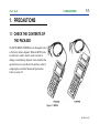
1. PRECAUTIONS
1.1 CHECK THE CONTENTS OF
THE PACKAGE
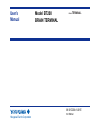
The BT200 BRAIN TERMINAL are thoroughly tested
at the factory before shipment. When the BT200 units
are delivered, visually check to make sure that no
damage occurred during shipment. Also check that the
specifications are as specified in the purchase order by
comparing those with the Model and Specification
Codes in section 2.2
Figure 1.1 BT200
IM 01C00A11-01E
<Toc> <Ind>
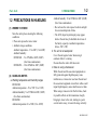
1.2 PRECAUTIONS IN HANDLING
(1) WHERE TO STORE
Store the unit in places meeting the following
conditions:
• Places not exposed to rain or water.
• Ambient storage conditions
Ambient temperature: -15 to 60°C (5 to 140°F)
Ambient humidity:
BT200-N00 ... 5 to 95%RH at 40°C (104°F)
(free from condensation)
BT200-P00 .... 30 to 80%RH at 40°C (104°F)
(free from condensation)
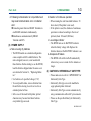
(2) HANDLING NOTES
a. Working temperature and humidity ranges
BT200-N00
Ambient temperature: -15 to 55°C (5 to 131°F)
Ambient humidity: 5 to 95%RH at 40°C (104°F)
(free from condensation)
BT200-P00
Ambient temperature: 0 to 50°C (32 to 122°F)
<1. PRECAUTIONS>
1-2
Ambient humidity: 30 to 85%RH at 40°C (104°F)
(free from condensation)
• Do not leave the unit exposed to direct sunlight
for an extended period of time.
• The LCD (liquid crystal display) may appear
dark or the unit may be disabled due to loss of
the battery capacity at ambient temperatures
below -15°C. (5°F)
b. The unit is not waterproof.
Cover the unit against water when using it
outdoors while it is raining.
Do not allow the unit to fall into water.
c. Note on using a transceiver
While the unit and the associated equipment are
fully protected against high-frequency noise
interferences, a transceiver used near the unit and
the associated equipment or near their cables could
impart high-frequency noise interferences to them.
When using a transceiver for the first time, check
its possible effects on the transmission loop by
bringing it closer to the unit, starting at a point
several meters away, to locate the range of safety.
IM 01C00A11-01E
<Toc> <Ind>
d. Following communication is not permitted as it
may result communication error or indication
error:
✽ Connecting more than two BRAIN Terminals to
one BRAIN instrument simultaneously.
✽ Simultaneous communication by BRAIN
Terminal and DCS.
(3) POWER SUPPLY
a. Note on using dry batteries
• The BT200 model on a standard configuration
comes complete with five alkali batteries. The
unit as shipped, however, is not loaded with
these batteries. Before starting to use the BT200,
load the batteries shipped under the same cover
as instructed in Section 6.1, “Replacing Batteries.”
• Use batteries of a specified voltage (1.5V).
• To avoid possible leaks, remove batteries from
the unit before leaving it out of service for an
extended period of time.
• In the case of the model with printer, printed
characters may become faint when batteries
except alkali type are used.
<1. PRECAUTIONS>
1-3
b. Duration of continuous operation
• When running the unit from alkali batteries: 50
hours least (if the printer is not used).
• If the printer is used, the duration of continuous
operation is reduced according to the rate of
printout (about 10 hours/1,000 lines).
c. Low-voltage indicator
• The BT200 turns on its BATTERY indicator
when the battery voltage falls. Replace the
batteries whenever the BATTERY indicator is on.
d. Autopower-off feature
• The BT200 will switch itself off automatically
when no key access is made for five minutes or
longer.
(4) CAUTION for INTRINSICALLY SAFE TYPE
• Please make sure to refer to “APPENDIX B” for
Intrinsically Safe Type.
• Intrinsically Safe type can not be modified to
equip optional printer afterward.
• Intrinsically Safe Type can not communicate by
using communication cable with 5-pin connector.
• Please use the specified baterry for Intrinsically
Safe Type.
IM 01C00A11-01E
<Toc> <Ind>
<1. PRECAUTIONS>
1-4
(5) EMC CONFORMITY STANDARDS
,
EN61326, AS/NZS 2064
IM 01C00A11-01E
<Toc> <Ind>
<2. INTRODUCTION TO BT200>
2-1
2. INTRODUCTION TO
BT200
The BT200 BRAIN TERMINAL is a portable terminal
used in a 4 to 20 mA DC signal line connected to a
BRAIN instrument (*1).
The 4 to 20 mA DC signal line between the BT200
and the BRAIN instrument can be superimposed with a
communication signal to achieve two-way communication.
Working as a master, the BT200 Permits:
(*1) BRAIN instrument
Any instrument in support of BRAIN communications, including field instruments, such as
differential pressure and pressure transmitters
(DPharp, UNI∆MARKII/COM-B), vortex flow
meters (YEWFLO style E, DigitalYEWFLO),
magnetic flow meters (ADMAG, ADMAG AE)
and temperature transmitters (YTA Series), and
CENTUM-XL signal conditioners (SC).
1. Setting and changing parameters for the BRAIN
instrument
2. Monitoring PV and MV values and self-check
information on the BRAIN instrument, and
3. Directing the BRAIN instrument to enter the
constant current output mode.
IM 01C00A11-01E
<Toc> <Ind>
<2. INTRODUCTION TO BT200>
2-2
2.1 WHAT THE BT200 CAN DO
The BT200 offers the following exclusive features:
Feature
Low-voltage alarm
Autopower-off
Security code-based
setup protection
Upload/download
Description
Turns on the BATTERY indicator when
the battery voltage falls.
Switches off the BT200 automatically
when no key access is made for five
minutes or longer.
Sets a security code to protect setup
parameters.
Entering the correct security code
permits alterations to the setup
parameters.
The BT200 is shipped without a
security code set so, you can alter the
setup parameters without having to
enter a security code.
(Upload to the BT200)
Records the setup data on the
BRAIN instrument connected to the
BT200 into the BT200’s memory in a
batch.
(Download to the instrument)
Writes uploaded data to another
BRAIN instruments, but not to one
having a different model name.
Printout
Supports seven modes of printout,
including listing of all parameters and
listing of downloaded data.
ID (identification
Sets an identification code for the
code) setup
BT200.
Language selection
Supports both English and Japanese
(between English and versions of operational messages.
Japanese)
The BT200 is shipped with the
message mode set to English.
LCD contrast control Permits controlling the LCD contrast
through startup and utility panels.
Print density control
Permits controlling the printout density
through a utility panel. the print
density level can be visually verified
from test printout.
T0201.EPS
IM 01C00A11-01E
<Toc> <Ind>
2.2 SPECIFICATION
Equipment Specifications
Applicable Equipment
DPharp, UNI∆/COM, YA63
ADMAG, ADMAG AE
YEWFLO Style E, DigitalYEWFLO
YTA Series
JUXTA, Signal Conditioner
Communication Signal Connection:
Dedicated cable, 1.1 m long(3.6 ft)
Communication Line:
Line length: Up to 2 km (1.24 mile)(0.75 to 1.25
mm2 instrumentation cable)
Load resistance: 250 to 600 Ω (including cable
resistance)
Load capacitance: 0.22µF or less
Load inductance: 3.3 mH or less
Power line spacing: 15 cm (6 inch) or more (avoid
parallel wiring.)
Display: LCD dot matrix, 21 characters 8 lines
Controls: Membrane switches (four function keys, 20
general operation keys, and one power switch)
2-3
<2. INTRODUCTION TO BT200>
Printer (BT200-P00): Thermal paper type
Power Supply: Five AA 1.5 V dry alkali batteries
(LR6/AM3(N))
Dimensions:
BT200-N00 · · · 22811051 mm
(9.04.32.0 inch)
BT200-P00 · · · 32111061 mm
(12.64.32.4 inch)
Approximate Weight:
BT200-N00 · · · 510 g (1.12 lb)
BT200-P00 · · · 700 g (1.54 lb)
Functional Specifications
Basic Functions:
• Setup, alteration, and display of parameters
BRAIN communication.
Additional Functions:
• Batch upload/download of data
• Setpoint Protection: Security code enter is required
to alter setpoints.
• Battery Alarm ··· An alarm message appearing on
the LCD signals low battery voltages.
IM 01C00A11-01E
<Toc> <Ind>
• Automatic Power-off ··· The terminal switches off
automatically if no key access is made for
approximetely 5 minutes.
• LCD contrast adjustment
• Printing (BT200-P00)
Printout Information
• All parameter lists
• Parameter list within each menu item
• Setup change data list
• Uploaded data list
• Display images
• Self check list
2-4
<2. INTRODUCTION TO BT200>
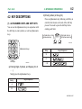
MODEL AND CODE
Model
Suffix codes
Description
· · · · · · · · · · BRAIN Terminal
-N · · · · · · With no printer
-P · · · · · · With printer
00 · · · · Always 00
Options
/䊐䊐
BT200
Printer
T0202.EPS
OPTIONS
Item
Description
Code
Communication Cable for SC
(Signal conditioner)
with 5-pin connector
CSA Intrinsically Safe
Approval
/C1
(Note 1)
Applicable only for model
BT200-N00 See Appendix B.
/CS1
(Note 1)
(Note 2)
T0203.EPS
Note 1: Optional Code /CS1 can not be combined with /C1.
Note 2: Applicable only for model BT200-N00.
PART NUMBERS
Item
with IC clips
Communication with alligator clips
with 3-pin connector
Cable
with 5-pin connector
Roll paper
Handy carrying case
Parts No.
F9182EA
F9182EB
F9182ED
F9182EE
F9182DS
F9182BP
T0204.EPS
IM 01C00A11-01E
<Toc> <Ind>
<2. INTRODUCTION TO BT200>
2-5
2.3 COMPONENT NAME
Fuigure 2.3 Component Name
IM 01C00A11-01E
<Toc> <Ind>
<2. INTRODUCTION TO BT200>
2-6
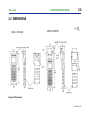
2.4 DIMENSIONS
Fuigure 2.4 Dimensions
IM 01C00A11-01E
<Toc> <Ind>
<3. CONNECTION >
3-1
3. CONNECTION
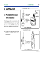
3.1 PLUGGING THE CABLE
INTO THE BT200
When plugging the dedicated communication cable
into the BT200, adjust the up arrow mark on the
cable to the ● mark on the BT200 connector and
push the cable into position until a click sounds.
Note: You cannot plug the connector cable for the BT100 into
the BT200, because the BT200 and BT100 have different
connector structures.
IM 01C00A11-01E
<Toc> <Ind>
<3. CONNECTION >
3-2
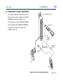
3.2 CONNECTION WITH BRAIN
SERIES INSTRUMENTS
(1) CONNECTION IN THE INSTRUMENT
TERMINAL BOXES
Some Brain Series equipment terminal boxes
have pins for connection to the BRAIN
TERMINAL. When connecting the BRAIN
TERMINAL to Brain Series equipment in the
field, connect as shown in Figure 3.2.a using
the BRAIN TERMINAL cable with IC clips.
Polarities are marked on the terminal box pins
and on the BRAIN TERMINAL
cable; however, no damage will occur if they
are connected with reverse polarity.
(2) CONNECTION IN RELAY TERMINAL
BLOCK
There are no dedicated pins for connecting to
the BRAIN TERMINAL in the field relay
terminal block or in the meter compartment
terminal block. In this case, use the cable with
the alligator clips.
Figure 3.2.a Connecting the BT200
IM 01C00A11-01E
<Toc> <Ind>
<3. CONNECTION >
3-3
(3) CONNECTION TO SIGNAL CONDITIONER
ESC (signal conditioner communication card) or
EXT (extension card) is provided with a BRAIN
TERMINAL connector (see Figure 3.2.b).
A 5-pin connector cable for the BRAIN TERMINAL is supplied when the BRAIN TERMINAL
comes with /C1 options. This cable is also
available at extra cost.
Figure 3.2.b Connection to Signal Conditioner
IM 01C00A11-01E
<Toc> <Ind>
<4. BT200 BASIC OPERATIONS >
4-1
4. BT200 BASIC OPERATIONS
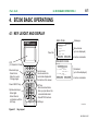
4.1 KEY LAYOUT AND DISPLAY
MENU PANEL
Panel title
Messages
Menu choices
(up to six displayed)
Function commands
PARAMETER PANEL
LCD
(21 character8 lines)
Movement keys
· Select items.
· Move the cursor.
· Change pages.
Function keys
Use to execute the
commands displayed at
the bottom of the screen.
Power ON/OFF key
ENT key
· Enters selected items.
· Sets up input data on the
connected instrument.
· Runs BT200 functions.
Alphanumeric keys
· Enter digits.
· Enter letters in
combination with the
shift keys.
MENU
BATTERY
A:DISPLAY
B:SETTING
C:ADJUST
I:CALIBRATION
K:TEST
M:CHECK DATA
HOME
SET
ADJ
ESC
PARAM
A10:OUTPUT
100.0 %
A11:ENGR. OUTPUT
1000 mmH2O
A20:AMP TEMP
23 deg C
HOME
SET
ADJ
PARM
Parameters
(up to three displayed)
Function commands
Shift keys
F0401.EPS
Figure 4.1
Key Layout
IM 01C00A11-01E
<Toc> <Ind>
4-2
<4. BT200 BASIC OPERATIONS >
4.2 KEY DESCRIPTIONS
(1) ALPHANUMERIC KEYS AND SHIFT KEYS
You can use the alphanumeric keys in conjunction with
the shift keys to enter symbols, as well as alphanumeric
keys.
b) Entering letters (A through Z)
Press an alphanumeric key following a shift key to
enter the letter shown on the side of the shift key
pressed. You need to press the shift key before
entering each letter.
Left-side letter on the
alphanumeric key
Right-side letter on
the alphanumeric key
F0404.EPS
Alphanumeric keys
Entry
Key-in Sequence
W
IC
Shift keys
F0402.EPS
J. B
a) Entering Digits, Symbols, and Spaces (0 to 9
...)
Simply press the alphanumeric keys.
Entry
F0405.EPS
Key-in Sequence
–4
0.3
F0403.EPS
IM 01C00A11-01E
<Toc> <Ind>
* Use the function key [F2] CAPS to select between
uppercase and lowercase (for letters only). The
case toggles between uppercase and lowercase
each time you press [F2] CAPS.
Entering uppercase
CODE
CAPS
4-3
<4. BT200 BASIC OPERATIONS >
CLR
* Use the function key [F1] CODE to enter symbols.
The following symbols will appear in sequence,
one at a time, at the cursor each time you press
[F1] CODE:
/ .-,+*)(’&%$#”!
Entering lowercase
ESC
Entry
CODE
caps
CLR
ESC
Key-in Sequence
To enter characters next to these symbols, press
[>] to move the cursor first.
Entry
to lower case
Key-in Sequence
symbol command
Boy
l/m
(B)
(o)
(y)
(I)
F0406.EPS
(/)
(m)
F0407.EPS
IM 01C00A11-01E
<Toc> <Ind>
4-4
<4. BT200 BASIC OPERATIONS >
(2) FUNCTION KEYS
The functions of the function keys depend on the
function commands on display.
FUNCTION COMMAND LIST
(FOR BT200-N00 & BT200-P00)
Command
ADJ
(FOR BT200-P00)
Function
Command
Displays the ADJ menu
CAPS/caps Selects uppercase or lowercase
CODE
Selects symbols
CLR
Erases input data or deletes all data
DATA
Updates parameter data
DEL
Deletes one character
DIAG
Calls the self-check panel
ESC
Function
COPY
Prints out parameters on display
FEED
Paper feed
LIST
Lists all parameters in the menu
PON/POFF Automatic printout mode on or off
PRNT
GO
STOP
Returns to the most recent display
Changes to the print mode
Starts printing
Cancels printing
T0401-2.EPS
HOME
Displays the menu panel
NO
Quits setup and returns to the previous display
OK
Proceeds to the next panel
PARM
SET
Enters the parameter number setup mode
Displays the SET menu
SLOT
Returns to the slot selection panel
UTIL
Calls the utility panel
MENU
A:DISPLAY
B:SETTING
C:ADJUST
I:CALIBRATION
K:TEST
M:CHECK DATA
HOME
SET
ADJ
ESC
Function commands
Function keys
T0401-1.EPS
F0408.EPS
IM 01C00A11-01E
<Toc> <Ind>
4-5
<4. BT200 BASIC OPERATIONS >
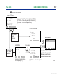
4.3 BT200 FUNCTION CONFIGURATION
(DPharp)
PARAM
01:MODEL
EJ110-DM
02:TAG NO.
TABC-101
03:SELF CHECK
GOOD
––WELCOME––
BRAIN TERMINAL
ID: BT200
check connection
push ENTER key
UTIL
OK
FEED
HOME
[Online]
[Offline]
MENU
J:ADJUST
K:TEST
M:MEMO
P:RECODE
MENU
C:SETTING
D:AUX SET 1
DATA SET
DIAG
PRNT
ESC
E:AUX
2
MENU
A:DISPLAY
B:SENSOR TYPE
DATA DIAG PRNT
ESC
SET
ADJ
ESC
PARAM
C60:SELF CHECK
GOOD
PARAM
C12:HIGH RANGE
1000 mmH2O
DATA DIAG
PRNT
C30:AMP
DAMPING
ESC
PARAM
C10:TAG NO.
TABC-101
DATA DIAG
ESC
C20:PRESS
UNITPRNT
mmH2O
C21:LOW RANGE
0 mmH2O
DATA DIAG PRNT
ESC
(SC)
FUNC
1.MENU
2.UPLOAD TO BT200
3.DOWNLOAD TO INST
4.PRINT ALL DATA
SLOT
SLOT NO.
UTILITY
1.ID
2.security code
3.LANGUAGE SELECT
4.LCD CONTRAST
5.PRINTER ADJUST
00
CLR
HOME
SET
ADJ
SET
C10:TAG NO.
TABC-101
TABC-101
ESC
CODE
CAPS
CLR
ESC
ESC
F0409.EPS
Figure 4.3 BT200 Function Configuration
IM 01C00A11-01E
<Toc> <Ind>
<4. BT200 BASIC OPERATIONS >
4-6
4.4 BASIC OPERATIONS
This section illustrates the basic operations of
the BT200-P00 (BRAIN TERMINAL with a
printer) with reference to online communication with DPharp, for example.
For the BT200-N00, the function commands
marked by a corrugated line ( ) and the
messages marked by an asterisk (*) are not
displayed.
(1) TURN THE POWER SWITCH ON OR
OFF
■ Startup panel
Turn on the BT200, and it comes up with the
panel shown below. (The message “Please wait
. . . ” will be displayed for seconds after the
unit is turned on.)
IM 01C00A11-01E
<Toc> <Ind>
4-7
<4. BT200 BASIC OPERATIONS >
POWER SWITCH ON
STARTUP PANEL
––WELCOME––
BRAIN TERMINAL
ID: BT200
check connection
push ENTER key
UTIL
Plug the cable into the instrument and press [ENT].
[F1] UTIL → Call a utility panel (See Section 5.3.)
[F2] FEED → Paper feed (BT200-P00)
FEED
INITIAL DATA PANEL
PARAM
01:MODEL
EJ110-DM
02:TAG NO.
TABC-101
03:SELF CHECK
GOOD
If connected to
a field
instrument
MENU PANEL
MENU
A:DISPLAY
B:SENSOR TYPE
OK
or
SLOT PANEL
Slot number
+
SLOT
If connected to
an SC (signal
conditioner)
SLOT NO.
00
CLR
Type the slot number of the
SC and press [ENT].
PARAM
01:MODEL
EJ110-DM
02:TAG NO.
TABC-101
03:SELF CHECK
GOOD
SLOT
HOME
OK
SET
ADJ
ESC
Check the model name and
tag number of the connected
instrument, and self-check
information associated with it.
[F3] SLOT → Return to slot panel.
F0410.EPS
IM 01C00A11-01E
<Toc> <Ind>
4-8
<4. BT200 BASIC OPERATIONS >
(2) DISPLAY PARAMETERS
a) Menu panel operations
The menu panel contains a list of up to six menu
choices in each page. Use [<] and [>] to change the
pages. Pressing [F1] HOME, [F2] SET, and [F3]
ADJ displays the menu in the block.
DPharp
If the menu choices are blocked (as with DPharp,)
the menus are displayed for each block.
HOME MENU PANEL
MENU
A:DISPLAY
B:SENSOR TYPE
HOME
[F1] HOME
[F2] SET
[F3] ADJ
[F4] ESC
[ENT]
Displays the menu panel.
Displays the SET menu panel.
Displays the ADJ menu panel.
Returns the command panel.
Enters selected menu choice.
SET
ADJ
ESC
SET MENU PANEL
ADJ MENU PANEL
MENU
C:SETTING
D:AUX SET 1
E:AUX SET 2
H:AUTO SET
HOME
SET
MENU
J:ADJUST
K:TEST
M:MEMO
P:RECORD
ADJ
ESC
HOME
SET
ADJ
ESC
F0411.EPS
IM 01C00A11-01E
<Toc> <Ind>
4-9
<4. BT200 BASIC OPERATIONS >
b) Call the parameter panel
On initial data panel, type [F4] OK or
[ENT] to call the starting [HOME menu
panel] of menu panel 4.
MENU
J:ADJUST
K:TEST
M:MEMO
P:RECODE
MENU
C:SETTING
D:AUX SET 1
DATA
DIAG
PRNT
ESC
HOME
MENU
E:AUX
SET
2PANEL
MENU
A:DISPLAY
B:SENSOR TYPE
DATA DIAG PRNT
ESC
INITIAL DATA PANEL
PARAM
01:MODEL
EJ110-DM
02:TAG NO.
TABC-101
03:SELF CHECK
GOOD
OK
Select a menu choice from menu panel
4 and press [ENT] to call parameter
panel 5.
HOME
>
<
The parameter panel displays up to three
parameters in each page. Use the
movement keys [ ], [ ], [<], and [>] to select
parameters.
Move the reverse bar up and
down to select parameters.
PARAM
C10:TAG NO.
TABC-101
C20:PRESS UNIT
mmH2O
C21:LOW RANGE
0 mmH2O
DATA DIAG PRNT
SET
ADJ
ADJ
SET
ESC
PARAM
C60:SELF CHECK
GOOD
PARAM
C22:HIGH RANGE
1000 mmH2O
C30:AMP DAMPING
2.0 SEC
C40:OUTPUT MODE
DATA DIAG PRNT
OUT:LIN DSP:LIN
DATA DIAG PRNT
ESC
ESC
ESC
Change pages.
DATA
Updates the current parameter. When you press this key, data is
read from the connected instrument for display through
telecommunications.
DIAG
Calls the self-check panel. (See Section 4.4(2)c)
F0412.EPS
PRNT Calls the parameter print panel. (See Section 5.2(2))
ESC
Exits from the current panel and returns to the previous panel
(menu panel).
F0413.EPS
IM 01C00A11-01E
<Toc> <Ind>
<4. BT200 BASIC OPERATIONS >
Helpful hint 1
• Typing letters in a panel allows you to make a direct
selection of the corresponding menu choices from
the panel.
1. While Menu panel is on display, type ‘K’ to select
the choice ‘K: TEST.’
2. On a utility panel or function panel, type digits
instead to make a direct selection of the corresponding utility functions.
MENU PANEL
MENU
A:DISPLAY
B:SETTING
C:ADJUST
I:CALIBRATION
K:TEST
M:CHECK DATA
HOME
SET
ADJ
MENU
A:DISPLAY
B:SETTING
C:ADJUST
I:CALIBRATION
K:TEST
M:CHECK DATA
HOME
SET
ADJ
PARAM
A10:OUTPUT
100.0 %
A11:ENGR. OUTPUT
1000 mmH2O
A20:AMP TEMP
23°C
DATA DIAG PRNT
or
2. Press [F4] PARM to change
the function commands to the
3.
commands shown on panel䊊
PARM
[F1] HOME ➝HOME parameter
panel.
[F2] SET ➝SET parameter
panel.
[F3] ADJ ➝ADJ parameter
panel.
[F4] PARM ➝Change the function
commands.
3
䊊
Type ‘3’
PARAM
A10:OUTPUT
100.0 %
A11:ENGR. OUTPUT
1000 mmH2O
A20:AMP TEMP
23°C
UTILITY
1.ID
2:security code
3.MESSAGE MODE
4.LCD CONTRAST
5.PRINTER ADJUST
1. Press a shift key on
1 to change
parameter panel 䊊
the function commands to the
2.
commands shown on panel 䊊
ESC
esc
ESC
ESC
1 PARAMETER PANEL
䊊
PARAM
A10:OUTPUT
100.0 %
A11:ENGR. OUTPUT
1000 mmH2O
A20:AMP TEMP
23°C
HOME
SET
ADJ
UTILITY
1.ID
2.security code
3.MESSAGE MODE
4.LCD CONTRAST
5.PRINTER ADJUST
Type ‘K’
Helpful hint 2
• Following procedure allows you to make a direct
selection of the parameter.
2
䊊
UTILITY PANEL
4-10
esc
Entry position
esc
F0414.EPS
F0415-1.EPS
IM 01C00A11-01E
<Toc> <Ind>
3
䊊
PARAM
A10:OUTPUT
100.0 %
A11:ENGR. OUTPUT
1000 mmH2O
A20:AMP TEMP
23°C
esc
While commands are
3 , type
displayed on panel 䊊
the number of a parameter to
be displayed and press [ENT]
to call the parameter panel for
the entered number.
Example: Call the parameter
panel ‘K10: OUTPUT X%’
3.
from panel 䊊
K10
ESC
c) Call the self-check panel
Press [F2] DIAG on a parameter panel to call a selfcheck panel. The self-check panel displays selfcheck information on the connected instrument. This
function is not available for signal conditioners.
PARAM
A10:OUTPUT
100.0 %
A11:ENGR. OUTPUT
1000 mmH2O
A20:AMP TEMP
23°C
DATA DIAG PRNT
ESC
(When errors occer)
➝Type ‘K10’ and press [ENT].
DIAG
C60:SELF CHECK
GOOD
4
䊊
3
[F2] A10 ➝Panel 䊊
[F4] ESC ➝Returns the function
commands to
commands shown
1 .
on panel 䊊
PARAM
K10:OUTPUT X %
0.0 %
K60:SELF CHECK
GOOD
A10
4-11
<4. BT200 BASIC OPERATIONS >
ESC
FEED
FEED
PRNT
ESC
PRNT
ESC
DIAG
C60:SELF CHECK
ERROR
<
ERROR
< OUT OF RANGE
< OVER SENS TEMP
< OVER OUTPUT
FEED
PRNT
Paper feed
Print (See Section 5.2(6).)
Returns to parameter panel
>
>
>
>
ESC
F0416.EPS
Number of the starting parameter on
the panel before the last
Number of the starting parameter on the
previous panel
F0415-2.EPS
IM 01C00A11-01E
<Toc> <Ind>
(
E
)
(
(
H
J
)
( – )
)
(
3
䊊
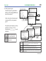
Change the tag number
Current: TABC-101 ➝ EJ-aH01
1. Select the parameter to
change with [ ], [ ], [<] or [>]
and press [ENT].
<
PARAM
C10:TAG NO.
TABC-101
C20:PRESS UNIT
mmH2O
C21:LRV
0 mmH2O
DATA DIAG PRNT
If you have set a security code,
you must enter the security
code. (See section (4))
CAPS
”
*PRINTER OFF
*F2:PRINTER ON
FEED POFF
NO
5
䊊
2. Enter data ‘EJ-aH01.’
SET
C10:TAG NO.
TABC-101
TABC-101
4
䊊
SET
C10:TAG NO.
TABC-101
“EJ-a01
ESC
2 SETUP PANEL
䊊
SET
C10:TAG NO.
EJ-a01
CLP
)
)
*PRINTER OFF
*F2:PRINTER ON
FEED PDFF
NO
>
1 PARAMETER PANEL
䊊
01
a
3. Press [ENT].
SET
C10:TAG NO.
TABC-101
EJ-a01
Example 1
(
]
]
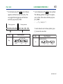
(3) CHANGE SETUP DATA
To change setup data, select a parameter to change
from parameter panel and press [ENT] to call setup
panel. If you have set a security code with a utility, that
code must be entered.
CODE
4-12
<4. BT200 BASIC OPERATIONS >
ESC
FEED
F0417-1.EPS
NO
OK
4. The setup data flashes for
your verification. Press [ENT]
to accept new tag number.
[F3] NO ➝Cancel the setup
procedure.
[F2] POFF ➝(See Section 5.2)
5. The setup procedure is
complete. The data on the
connected instrument is
rewritten.
[F3] NO ➝Retry the data setup.
[F4] OK ➝Return to the
parameter panel.
F0417-2.EPS
IM 01C00A11-01E
<Toc> <Ind>
<4. BT200 BASIC OPERATIONS >
4-13
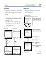
Example 2
Change the unit.
Current: mmH2O ➝ kPa
1. Select the parameter to
change with [ ], [ ], [<] or [>]
and press [ENT].
<
PARAM
C10:TAG NO.
TABC-101
C20:PRESS UNIT
mmH2O
C21:LRV
0 mmH2O
DATA DIAG PRNT
3 SETUP PANEL
䊊
FEED
ESC
If you have set a security code,
you must enter the security
code. (See section (4))
2 SETUP PANEL
䊊
>
>
>
>
>
2. Select the setup data with
[ ], [ ], [<] or [>] and press
[ENT] twice to complete the
setup procedure.
<
SET
C20:PRESS UNIT
mmH2O
< fnHg
< ftH2O
< psi
< atm
SET
C20:PRESS UNIT
kPa
>
1 PARAMETER PANEL
䊊
ESC
NO
OK
3. The setup procedure is
complete.
[F1] FEED ➝Paper feed.
[F3] NO ➝Retry the data
setup.
[F4] OK ➝Return to the
parameter panel.
inHg
ftH2O
psi
atm
mmH2O
mmAg
mmWG
mmHg
Torr
kPa
MPa
mbar
bar
gf/cm2
kgf/cm2
inH2O
F0418-1.EPS
F0418-2.EPS
IM 01C00A11-01E
<Toc> <Ind>
(4) ENTER A SECURITY CODE (IF ONE HAS
BEEN SET)
To alter setup data for the first time after switching on
the BT200, select the security code setup panel. You
must type the correct security code, in order to rewrite
parameters for the connected instrument.
You must to type the security code only once after the
BT200 is switched on. Reentry is not needed until you
switch off the BT200.
<4. BT200 BASIC OPERATIONS >
4-14
PARAMETER PANEL
PARAM
C10:TAG NO.
TABC-101
C20:PRESS UNIT
mmH2O
C21:LRV
0 mmH2O
DATA DIAG PRNT
ESC
1. Select ‘C10: TAG No.’ and
press [ENT] to change the tag
number.
‘SECURITY CODE SETUP
Panel’ is displayed only if the
tag number is changed for the
first time.
SECURITY CODE
SETUP PANEL
2. Type the security code (four
digits) and press [ENT].
SECURITY
ID:BT200
SECURITY CODE
:***_
CLR
ESC
****
SETUP PANEL
✻ If you type the wrong security
code and press [ENT], the
message “incorrect CODE” is
displayed. Type the correct
security code.
SET
C10:TAG NO.
TABC-101
TABC-101
CODE
CAPS
CLR
ESC
F0419.EPS
IM 01C00A11-01E
5-1
<Toc> <Ind>
<5. USING THE BT200 FUNCTIONS >
5. USING THE BT200
FUNCTIONS
(1) COPY TO THE BT200 IN A BATCH
(UPLOAD)
First, it is necessary to copy the settings for a particular
instrument into the BT200 in a batch. The items from
the SET menu can be copied.
5.1 SETTING UP DATA IN A
BATCH (UPLOAD/DOWNLOAD)
Where a number of instruments are used, many units
might have virtually identical settings. In this situation,
the setup procedure can be simplified by copying the
settings for one instrument into another in a batch, then
making necessary modifications to that data. This setup
technique helps standardize the operating state of each
individual instrument and reduces the chances of
improper settings.
1
䊊
1. Connect the BT200 to the
instrument and make it ready
for communication.
Press [F4] ESC on the menu
2 .
panel to call panel 䊊
MENU
A:DISPLAY
B:SENSOR TYPE
HOME
SET
ADJ
2
䊊
FUNC
1.MENU
2.UP LOAD TO HHT
3.DOWN LOAD TO INST
4.PRINT ALL DATA
HOME
SET
ESC
2. Select ‘2. UPLOAD TO HHT’
and press [ENT]
HHT(Handheld terminal):
BT200
ADJ
This function does not apply to certain instruments,
such as signal conditioner cards.
F0501-1.EPS
IM 01C00A11-01E
<Toc> <Ind>
5-2
<5. USING THE BT200 FUNCTIONS >
3
䊊
3. The model name of the
connected instrument is
displayed, check it and press
[ENT].
UP LOAD
MODEL
EJ110-DM
UPLOAD start?
push ENTER key
(2) GLOBAL COPY (DOWNLOAD)
Downloading copies the settings stored in the BT200
into other instruments in a batch, but not into different
models.
1
䊊
ESC
1. Connect the BT200 to the
other instrument and make it
ready for communication.
Press [F4] ESC on the menu
2 .
panel to call panel 䊊
MENU
A:DISPLAY
B:SENSOR TYPE
4
䊊
UP LOAD
MODEL
EJ110-DM
communi.
UPLOADING
please wait...
4. An upload is executed and a
transfer starts.
4 is displayed while the
Panel 䊊
transfer is in progress.
HOME
SET
ADJ
2
䊊
5
䊊
5. The transfer is complete
when panel 䊊
5 appears.
UP LOAD
MODEL
EJ110-DM
UPLOAD complete
F3:print data
PRNT
ESC
[F3] PRNT ➝Print uploaded data.
(See section 5.2(5).)
[F4] ESC ➝Return to the
function panel.
FUNC
1.MENU
2.UPLOAD TO HHT
3.DOWNLOAD TO INST
4.PRINT ALL DATA
HOME
SET
ESC
2. Select ‘3. DOWNLOAD TO
INST’ and press [ENT].
ADJ
F0501-2.EPS
Because the data is written to the BT200’s nonvolatile
memory, it is preserved intact even when the terminal
is switched off.
F0502-1.EPS
IM 01C00A11-01E
<Toc> <Ind>
5-3
<5. USING THE BT200 FUNCTIONS >
3
䊊
DNLOAD
MODEL
EJ110-DM
DOWNLOAD start?
push ENTER key
ESC
4
䊊
DNLOAD
MODEL
EJ110-DM
communi.
DOWNLOADING
please wait...
5
䊊
3. Check the model name
2 and
displayed on panel 䊊
that of the instrument into
which data is downloaded.
Data connot be downloaded
into an instrument having a
different model name. Press
[ENT] to execute a download.
4. A download is executed and a
transfer starts.
4 is displayed while the
Panel 䊊
transfer is in progress.
* If the model name is unmatched, the message
“MODEL mismatch” is displayed. Press [F4] ESC
2.
return to panel 䊊
6
䊊
DOWN LOAD
NO DATA TO DOWNLOAD
ESC
F0503.EPS
5. The transfer is complete
when panel 䊊
5 appears.
DNLOAD
MODEL
EJ110-DM
DOWNLOAD complete
F3:print data
PRNT
ESC
[F3] PRNT ➝Print uploaded data.
(See section 5.2(5).)
[F4] ESC ➝Return to the
function panel.
F0502-2.EPS
* When there is no data to download (because an
upload has not been successfully ended), panel 䊊
6 is
displayed, indicating that downloading is not
operable.
IM 01C00A11-01E
5-4
<Toc> <Ind>
<5. USING THE BT200 FUNCTIONS >
5.2 USING PRINTER FUNCTIONS
(1) PRINTING CHANGED SETUP DATA
1 SETUP PANEL
䊊
(BT200-P00)
The BT200-P00 BRAIN TERMINAL with a printer
can print in the following modes:
CODE
Prints out old and new versions
of the data on the setup panel.
Prints out data displayed on a
panel.
Prints out all the parameters,
from A10 to A60, for menu
choice A, for example.
4. Listing of all parameters Prints out an entire list of
parameters.
Prints out a list of self-check
5. Listing of self-check
information (such as error
information
information) designated by the
DIAG key.
1 Uploaded data list prints out
6. Listing of uploaded or
䊊
data after it has been
downloaded data
uploaded.
2 Downloaded data list prints
䊊
out data after it has been
downloaded.
1. Listing of setup data
and changed data
2. Listing of display
parameters
3. Listing of all parameters
from a menu
1. Enter new data into the setup
panel and press [ENT] to
select the setup data
2.
verification panel 䊊
SET
C10:TAG NO.
TABC-101
PFT-001_
CAPS
CLR
ESC
2
䊊
2. Press [F2] POFF changes to
PON . (To turn on the printout
mode.)
print off
F2:printer on
FEED
POFF
NO
3
䊊
3. Press [ENT] to set the update
data in the instrument and
print out both the old and new
versions of data.
print setting data
F2:printer off
FEED
PON
NO
4
䊊
The printout covers the
parameter number, name, old
data, and new data.
SETTING
C10:TAG NO.
PFT-001
T0501.EPS
FEED
NO
OK
C10:TAG NO.
old> TABC-101
new> DABC-123
(Sample printout)
F0504.EPS
IM 01C00A11-01E
5-5
<Toc> <Ind>
<5. USING THE BT200 FUNCTIONS >
(2) PRINTING DISPLAY PARAMETERS
(3) PRINTING ALL PARAMETERS FROM A
MENU CHOICE
1
䊊
PARAM
A10:OUTPUT
100.0 %
A11:ENGR. OUTPUT
1000 mmH2O
A20:AMP TEMP
23 deg C
DATA DIAG PRNT
ESC
2
䊊
PARAM
A10:OUTPUT
100.0 %
A11:ENGR. OUTPUT
1000 mmH2O
A20:AMP TEMP
23 deg C
FEED COPY LIST
ESC
1. Press [F4] PRNT on
1 to change
parameter panel 䊊
the function commands.
1
䊊
2. Press [F2] COPY to print out
only the parameters
appearing on the display
panel.
2
䊊
A10:OUTPUT
100.0 %
A11:ENGR.OUTPUT
1000 mmH2O
A20:AMP TEMP
23 deg C
PARAM
A10:OUTPUT
100.0 %
A11:ENGR. OUTPUT
1000 mmH2O
A20:AMP TEMP
23 deg C
DATA DIAG PRNT
ESC
PARAM
A10:OUTPUT
100.0 %
A11:ENGR. OUTPUT
1000 mmH2O
A20:AMP TEMP
23 deg C
FEED COPY LIST
ESC
3
䊊
(Sample printout)
F0505.EPS
PRINT
A:DISPLAY
print data in menu
TITLE
[
]
DATE
[ - ]
TIME
[
:
]
F3:start printing
FEED CAPS
GO
ESC
1. Press [F4] PRNT on
parameter panel 䊊
1 to change
the function commands.
2
2. Press [F3] LIST on panel 䊊
3.
to call print panel 䊊
3. If you type the title, date, and
time, they print out together
with the input data.
Enter the data into print panel
3.
䊊
(Printing can be started even
if the title, date, and time are
left unspecified.➝press [F3]
GO)
F0506-1.EPS
IM 01C00A11-01E
<Toc> <Ind>
5-6
<5. USING THE BT200 FUNCTIONS >
4
䊊
PRINT
A:DISPLAY
print data in menu
TITLE [DISPLAY ]
DATE
[94-05-15]
TIME
[ 10:00 ]
F3:start printing
FEED
GO
ESC
4. Press [F3] GO to start
printing.
Pressing [ENT] with the
cursor on “TIME” will also
start printing.
2
䊊
2. Select ‘4.PRINT ALL DATA’
2 and
from command panel 䊊
press [ENT].
FUNC
1.MENU
2.UPLOAD TO HHT
3.DOWNLOAD TO INST
4.PRINT ALL DATA
HOME
SET
ADJ
or
5
䊊
5 is displayed while
5. Panel 䊊
printing is in progress. Press
[F4] STOP until printing stops
in order to cancel printing.
PRINT
menu data printing
please wait...
F4:STOP printing
STOP
The message “PRINTING
END” appears when the
printing is complete.
F0506-2.EPS
3
䊊
LIST
print ALL data LIST
TITLE
[
]
DATE
[ - ]
TIME
[
:
]
F3:start printing
FEED CAPS
GO
ESC
4
䊊
3 is displayed while
4. Panel 䊊
printing is in progress. Press
[F4] STOP until printing stops
in order to cancel printing.
PRINT
(4) PRINTING ALL PARAMETERS
1
䊊
HOME
SET
ADJ
all data printing
please wait...
1. Connect the BT200 to the
other instrument and make it
ready for communication.
Press [F4] ESC on the menu
2.
panel to call panel 䊊
MENU
A:DISPLAY
B:SENSOR TYPE
3. Type the title, date, and time,
and press [F3] GO to start
printing.
(Printing can be started even
if the title, date, and time are
left unspecified.)
F4:STOP printing
STOP
The message “PRINTING
END” appears when the
printing is complete.
F0507-2.EPS
ESC
F0507-1.EPS
IM 01C00A11-01E
<Toc> <Ind>
<5. USING THE BT200 FUNCTIONS >
(5) PRINTING UPLOADED OR DOWNLOADED
DATA
a) UPLOAD
1
䊊
1 appears following the
1. Panel 䊊
completion of an upload.
(refer to section 5.1(1))
Press [F3] PRNT to display
2.
panel 䊊
UPLOAD
MODEL
EJ110-DM
UPLOAD normal end
F3:print data
PRNT
b) DOWNLOAD
following the end of a download, the downloaded
data can be printed out by following the procedural steps similar to printing out uploaded data
explained in a) UPLOAD.
NOTE
ESC
2
䊊
UPLOAD
print UPLOAD data
LIST
TITLE
[
]
DATE
[ - ]
TIME
[
:
]
F3:start printing
FEED CAPS
GO
5-7
2. Type the title, date, and time,
and press [F3] GO to start
printing.
Printing of uploaded or downloaded data is
executed while communicating with the connected instrument. Unplugging the cable while
printing would cause a communication error to
occur, canceling communication.
ESC
3
䊊
UPLOAD
UPLOAD data printing
please wait...
F4:STOP printing
STOP
3. The message “UPLOAD data
printing please wait...” is
displayed while the printing is
in progress.
Press [F4] STOP to cancel
printing.
The message “PRINTING
END” appears when the
printing is complete.
F0508.EPS
IM 01C00A11-01E
<Toc> <Ind>
<5. USING THE BT200 FUNCTIONS >
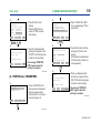
(6) PRINTING A LIST OF SELF-CHECK INFORMATION
5.3 OFFLINE FUNCTIONS
1
䊊
DATA
DIAG
Call The Offline Menu (UTILITY PANEL)
1. Press [F2] DIAG on the
parameter panel to call self1 .
check panel 䊊
PARAM
C10:TAG NO.
TABC-101
C20:PRESS UNIT
mmH2O
C21:LRV
--WELCOME-BRAIN TERMINAL
ID:BT200
0 mmH2O
PRNT
ESC
check connection
push ENTER key
2
䊊
DIAG
C60:SELF CHECK
ERROR
<ERROR
>
<OUT OF RANGE >
<OVER SENS TEMP>
<OVER OUTPUT
>
FEED
PRNT
2. Press [F3] PRNT to start
printing.
ESC
[F1] FEED ➝Paper feed
[F3] PRNT ➝Print out self-check
information.
[F4] ESC ➝Return to the
1.
parameter panel 䊊
5-8
UTIL
FEED
UTILITY
1.ID
2.SECURITY CODE
3.LANGUAGE SELECT
4.LCD CONTRAST
5.PRINTER ADJUST
ESC
F0510.EPS
F0509.EPS
IM 01C00A11-01E
5-9
<Toc> <Ind>
<5. USING THE BT200 FUNCTIONS >
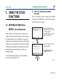
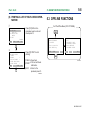
(1) ID (Identification Code) SETUP
Each BT200 BRAIN TERMINAL is assigned an ID
(identification code) to identify itself from other
terminals. The ID is displayed on the startup panel
and the security code setup panel. You can change
the ID from the utility panel. The ID is up to eight
characters long.
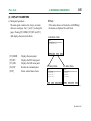
(2) LANGUAGE SELECTION (BETWEEN
ENGLISH AND JAPANESE)
a) English to Japanese
1
䊊
1
䊊
LANGUAGE
1.ENGLISH
2.JAPANESE
ESC
1. Select ‘1.ID’ from the utility
1.
panel to call panel 䊊
Type the new ID and press
[ENT] twice.
ID
ID:BT200
set new ID
_
CODE
CAPS
CLR
ESC
F0511.EPS
1. Select ‘3. LANGUAGE
SELECT’ from the utility panel
1.
to select the panel 䊊
If you Select ‘2. JAPANESE’
and press [ENT], the
message mode is switched to
Japanese.
2
䊊
LANGUAGE
1.ENGLISH
2.JAPANESE
1.
[F3] NO ➝Return to panel 䊊
3.
[F4] OK ➝Go to panel 䊊
change JAPANESE
NO
OK
3
䊊
[F4] ESC ➝Start
communication,
returning to the
initial data panel.
F0512.EPS
IM 01C00A11-01E
<Toc> <Ind>
<5. USING THE BT200 FUNCTIONS >
b) Japanese to English
1
䊊
4
䊊
3.
[F3] NO ➝Return to panel 䊊
5.
[F4] OK ➝Go to panel 䊊
1. Press [F1] to select the unility
2 in Japanese.
panel 䊊
5
䊊
2
䊊
3
䊊
5-10
2. Select
and press [ENT] to go to
3 .
panel 䊊
[F4] ESC ➝Start
communication,
returning to the
initial data panel.
UTILITY
1.ID
2.SECURITY CODE
3.LANGUAGE SELECT
4.LCD CONTRAST
5.PRINTER ADJUST
ESC
F0515-2.EPS
3. Select
and press [ENT] to go to
4 for confirmation.
panel 䊊
F0515-1.EPS
IM 01C00A11-01E
<Toc> <Ind>
<5. USING THE BT200 FUNCTIONS >
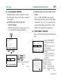
(3) LCD CONTRAST CONTROL
The BT200 features software capability to control
the LCD contrast. There are two ways to control the
LCD contrast.
a) CONTROLLING THE LCD ON THE
STARTUP PANEL
While the startup panel is on display, press [<] or
[>] to call the LCD contrast panel directly.
--WELCOME-BRAIN TERMINAL
ID:BT200
UTIL
b) CONTROLLING THE LCD ON THE UTILITY
PANEL
Select ‘4. LCD CONTRAST’ from the utility
panel and press [ENT] to select the LCD contrast
control panel. Use [<] or [>] to control the LCD
contrast. When finished, press [ENT] to set the
BT200 to the specified LCD contrast level.
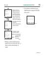
(4) PRINT DENSITY CONTROL
You can control the print density while printing test
copies.
1
䊊
PRINTER
printer adjust
Low
High
check connection
push ENTER key
FEED
push [<][>] key
F2:print test data
FEED
GO
or
Lighter.
Darker.
Set.
LCD
LCD contrast adjust
Low
High
push [<][>] key
ESC
Test printout
[F4] ESC ➝Return to the utility
panel.
F0513.EPS
5-11
!”#$%&’()*+,-./
0123456789:;<=>?
@ABCDEFGHIJKLMNO
PQRSTUVWXYZ[\]^_
ⱊabcdefghijklmno
pqrstuvwxyz{}˜
ESC
1. Select ‘6. PRINT DENSITY
CONTROL’ from the utility
panel.
2. Press [F2] GO on panel 1 to
start test printing.
(Press [F4] STOP to cancel
printing.)
3. Verify that test printout and
use [<] or [>] to control the
print density.
Repeat Steps 2 and 3 to finally
control the print density.
[F1] FEED ➝Paper feed
[F2] GO ➝Start test printing
[F4] ESC ➝Return to the utility
panel.
F0514.EPS
IM 01C00A11-01E
<Toc> <Ind>
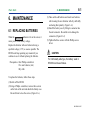
6. MAINTENANCE
6.1 REPLACING BATTERIES
When the BATTERY indicator is lit on the screen, it
warns you of a low battery voltage.
Replace the batteries with new batteries having a
specified voltage (1.5 V) as soon as possible. The
BT200 could stop operating any moment if you
continue to use it without replacing the batteries.
Prerequisites : One Phillips screwdriver
: Five new batteries (AA)
: Dry cloth
<6. MAINTENANCE>
6-1
(3) Take out the old batteries and insert new batteries
after cleaning the new batteries with dry cloth fully
and noting their polarity. (Figure 6.1.c)
(4) Install the battery case by fitting its connector into
the unit connector. Be careful not to damage the
connectors. (Figure 6.1.d)
(5) Tighten the three screws with the Phillips screwdriver.
CAUTION
For intrinsically safe type, the battery used in
BT200 must be as follows.
To replace the batteries, follow these steps.
(1) Switch off the BT200.
(2) Using a Phillips screwdriver, remove three screws
on the back of the unit and detach the battery case.
Be careful not to lose the screws. (Figure 6.1.a)
IM 01C00A11-01E
<Toc> <Ind>
<6. MAINTENANCE >
Manufacture
Model
Type
Voltage
DURACELL
MN1500
(PC1500)
Alkalinemanganese
1.5 V
6-2
Figure 6.1.a Removing Screws
IM 01C00A11-01E
<Toc> <Ind>
<6. MAINTENANCE>
6-3
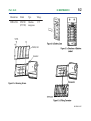
6.2 LOADING ROLL PAPER
With the BT200-P00 BRAIN TERMINAL with a
printer, follow these steps to load roll paper.
(1) Open the cover.
(2) Cut the end of the roll paper as shown.
(3) Insert the cut end of the roll paper into part A. The
roll paper has its face and back. Insert the roll paper
to face as shown in Figure 6.2.
(4) Push in the roll paper until its end comes out of part
B.
When the roll paper comes out, pull it out by using
your fingers.
(5) Lead the roll paper through slit c in the cover and
close the cover.
(6) Switch on the BT200 and press [F2] FEED on the
startup panel. Make sure that the roll paper is fed
correctly.
Figure 6.2
Loading Roll Paper
IM 01C00A11-01E
<Toc> <Ind>
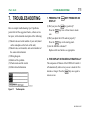
7. TROUBLESHOOTING
Here are simple troubleshooting tips. If problems
persist after all the suggested checks, callour service
for repair, with a detailed description of the following:
(1) Model code and serial number of your unit (found
on the nameplate on the back of the unit).
(2) Model code, serial number, and control number of
the connected instrument.
(3) Wiring diagram
(4) Details of the problem
(5) Checks made and the results
(6) Other related information
Figure 7.1
7-1
<7. TROUBLESHOOTING>
1. PRESSING THE
DISPLAY
(1) Did you press the
KEY PRODUCES NO
key positively?
Press the
key two or three times to make
sure.
(2) Did you adjust the LCD contrast properly?
key on the startup panel.
Press the
(3) Are the batteries exhausted?
Replace with new batteries as appropriate.
2. THE DISPLAY IS ERASED AUTOMATICALLY
The autopower-off feature of the BT200 will switch it
off automatically when no key access is made for five
minutes or longer. Press the
key once again to
restore screen.
The Nameplate
IM 01C00A11-01E
<Toc> <Ind>
3. THE BATTERY INDICATOR IS ON
The BATTERY indicator, when on, warns you of a low
battery voltage. Replace with new batteries having a
specified voltage (1.5 V) as soon as possible. The
BT200 could stop operating at any moment if you
continue to use it.
4. THE BT200 STOPS WITH THE COMMUN.
ERROR INDICATION ON
The BT200 needs to communicate with the connected
instrument in order to function. It doesn’t operate by
itself. This problem suggests that communication
between the BT200 and the connected instrument is
disabled.
(1) Are the BT200 and the instrument wired as instructed in the relevant instruction manuals?
Check again to make sure.
(2) Is the connected instrument switched on? Is it
operable?
Check again to make sure.
(3) Is a reception resistor of 250 ohms or higher
inserted in series in the current output circuit of the
connected instrument? If you are using our
<7. TROUBLESHOOTING>
7-2
distributor to power the connected instrument, a
reception resistor is built in it.
(4) Does the wiring distance of the current output cable
of the connected instrument exceed 2 km(1.24
miles)? Is a capacitor in excess of 0.22 F inserted
in parallel with the current output cable of the
mating instrument?
In either case, the communication signal components
are bypassed by the electrostatic capacitance,
disabling communication. Check again to make sure.
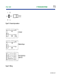
(5) Is the communication cable for the BT200 broken?
If a spare cable is available, replace it. If not, use a
multimeter to check for breakage with reference to
the connections shown below. (Figure 7.2)
6. SELF CHK ERROR INDICATION IS ON
The SELF CHK ERROR indication, when on, suggests
that a setting is out of range or a fault exists. Press [F2]
DIAG on the parameter panel to check the settings. For
detailed definitions of the diagnostic messages and the
associated actions, refer to the user’s manual for the
connected instrument
IM 01C00A11-01E
<Toc> <Ind>
<7. TROUBLESHOOTING>
7-3
Figure 7.2 Connector pin numbers
Figure 7.3 Wiring
IM 01C00A11-01E
<Toc> <Ind>
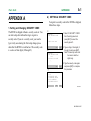
APPENDIX A
1. Setting and Changing SECURITY CODE
The BT200 is shipped without a security code set. You
can alter setup data without having to register a
security code. If you set a security code, you need to
type it only once during the first setup change procedure after the BT200 is switched on. The security code
is a series of four digits (0 through 9).
<APPENDIX>
A-1
A) SETTING A SECURITY CODE
To register a security code in the BT200 as shipped,
follow these steps.
1
䊊
1. Select ‘2. SECURITY CODE’
from the utility panel and
press [ENT] to select the
security panel 䊊
1.
SECURITY
new SECURITY CODE
:_
CODE clear mode
CLR
ESC
2
䊊
SECURITY
new SECURITY CODE
:****
re-enter new CODE
:_
CLR
ESC
3
䊊
2. Type a string of four digits (0
through 9) and press [ENT].
Note: The security code must
be numeric and four
digits long.
3. Type the security code again
and press [ENT] to complete
the procedure.
UTILITY
1.ID
2.SECURITY CODE
3.LANGUAGE SELECT
4.LCD CONTRAST
5.PRINTER ADJUST
CLR
ESC
F0A01.EPS
IM 01C00A11-01E
<Toc> <Ind>
<APPENDIX>
B) CHANGING THE SECURITY CODE
To change a security code after it has been registered, follow these steps.
1
䊊
1.
1. Select the security panel 䊊
SECURITY
old SECURITY CODE
:_
CLR
ESC
2
䊊
SECURITY
new SECURITY CODE
:_
2. Type the current security code
and press [ENT].
If you type a code different
from the registered security
code, the message “incorrect
CODE” is displayed. Press
[F4] ESC and retry.
2. Canceling a SECURITY CODE
To cancel a registered security code, follow these steps.
1
䊊
ESC
3
䊊
SECURITY
new SECURITY CODE
:****
re;enter new CODE
:_
CLR
ESC
4. Type the new security code
again and press [ENT] to
complete the procedure.
If you type a different code,
the message “incorrect CODE
set CODE again” is displayed.
Retry from Step 2 downward.
4
䊊
1.
1. Select the security panel 䊊
Type the old current security
code and press [ENT].
SECURITY
old SECURITY CODE
:_
CLR
ESC
2
䊊
2. Type ‘PASS’ instead of a new
security code.
3. The message “CODE clear
mode” is displayed.
SECURITY
new SECURITY CODE
:_
4. Press [F4] ESC to complete
the procedure.
3. Type a new security code and
press [ENT].
CLR
A-2
CLR
ESC
3
䊊
SECURITY
new SECURITY CODE
:
CODE clear mode
ESC
4
䊊
UTILITY
1.ID
2.SECURITY CODE
3.LANGUAGE SELECT
4.LCD CONTRAST
5.PRINTER ADJUST
UTILITY
1.ID
2.SECURITY CODE
3.LANGUAGE SELECT
4.LCD CONTRAST
5.PRINTER ADJUST
CLR
ESC
F0A03.EPS
CLR
ESC
F0A02.EPS
IM 01C00A11-01E
<Toc> <Ind>
<APPENDIX>
A-3
3. When You Forget the SECURITY CODE
When you forget the security code that has been
registered and register a new security code from the
beginning, follow these steps.
1
䊊
1 and
1. Call security panel 䊊
type‘RSET’.
SECURITY
old SECURITY CODE
:_
2. Type a new security code and
press [ENT].
CLR
ESC
2
䊊
3. Type the new security code
again and press [ENT] to
complete the procedure.
SECURITY
new SECURITY CODE
:_
4. Press [F4] ESC to complete
the procedure.
CLR
ESC
4
䊊
3
䊊
SECURITY
new SECURITY CODE
:****
re-enter new CODE
:_
CLR
UTILITY
1.ID
2.SECURITY CODE
3.LANGUAGE SELECT
4.LCD CONTRAST
5.PRINTER ADJUST
ESC
CLR
ESC
F0A04.EPS
IM 01C00A11-01E
<Toc> <Ind>
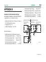
APPENDIX B
Installation of CS Intrinsically Safe Type
BT200 BRAIN TERMINAL (Model BT200-N00/CS1)
is applicable for use in hazardous locations;
• Intrinsically Safe for Class I, Division 1, Groups A,
B, C & D Hazardous Locations.
• Temperature Class: T4
• Ambient Temperature: -15 to 55°C
A-4
<APPENDIX>
The Maximum Output Voltage
Vmax(out)=2V
The Maximum Output Current Imax(out)=22mA
The Maximum Output Power Pmax(out)=11mW
The Maximum Allowed Capacitance Ca=3000µF
The Maximum Allowed Inductance
La=30mH
Hazardous Location
Non-hazardous Location
Intrinsically Safe
Apparatus
Safety Barrier
General Purpose
Equipment
+
+
+
+
–
–
–
–
Electrical Parameters
• BT200 Intrinsically Safe Apparatus Parameters
The Maximum Input Voltage
Vmax(in)=30V
The Maximum Input Current
Imax(in)=165mA
The Maximum Input Power
Pmax(in)=0.9W
The Maximum Internal Capacitance
Ci=0
The Maximum Internal Inductance
Li=730µH
BT200
+
–
F0B01.EPS
IM 01C00A11-01E
<Toc> <Ind>
• Safety Barriers Parameters (CSA Certified Barriers)
Voc 28V
Isc 143mA
Pmax 889mW
• Intrinsically Safe Apparatus Connected with BT200
(CSA Certified Apparatus)
Vmax (Voc of Safety Barrier) +2V
Imax (Isc of Safety Barrier) + 22mA
Pmax (Pmax of Safety Barrier) + 11mW
Installation
• All wiring shall comply with Canadian Electrical
code Part I and Local Electrical Codes.
• General purpose equipment connected to barrier
must not use or not generate more than 250 Vrms or
Vdc.
• The safety barriers and intrinsically safe apparatus
connected with BT200 must be certified by CSA.
<APPENDIX>
A-5
• Associated apparatus manufacturer’s installation
drawing must be followed when installing these
intrinsically safe apparatuses.
• Not a warning label worded:
“SUBSTITUTION OF COMPONENTS MAY
IMPAIR INTRINSIC SAFETY” and “TO PREVENT IGNITION OF A HAZARDOUS ATMOSPHERE, BATTERIES MUST ONLY BE
CHANGED IN AN AREA KNOWN TO BE
NONHAZARDOUS” and “USE IN ACCORDANCE WITH INSTRUCTION MANUAL IM
1C0A11-01E”.
• The battery used in BT200 must be as follows.
Manufacture Model
Type
Voltage
DURACELL MN1500
Alkaline1.5 V
(PC1500) manganese
• The instrument modification or parts replacement by
other than authorized representative of Yokogawa
Electric Corporation and Johnson Yokogawa
Corporation is prohibited and will void Canadian
Standard Association Intrinsic Safety Certification.
IM 01C00A11-01E
<Toc> <Ind>
R-1
<REVISION RECORD>
REVISION RECORD
Title: Model BT200 BRAIN TERMINAL
Manual No.: IM 01C00A11-01E
Edition Date
Page
Revised Item
1994
1st
New Publication
May
2nd 1996 CONTENTS · Add Subsection 1.2(4) ‘CAUTION
April
FOR INTRINSICALLY SAFE
TYPE’, Subsection 1.2(5) ‘EMC
Conformity Standards’ and
Appendix B.
1-2
· Add description ‘e’
(Subsection 1.2(2))
1-3
· Add description for printing
(Subsection 1.2(3)a)
· Add Subsection 1.2(4) ‘CAUTION
for INTRINSICALLY SAFE
TYPE’
1-4
· Add Subsection 1.2(5) ‘EMC
CONFORMITY STANDARDS’
2-4
· Add optional code /CS1.
(Subsection 2.2)
4-4
· Error correction (FUNCTION
COMMAND LIST)
6-1
· Add ‘CAUTION’ FOR
INTRINSICALLY SAFE TYPE
(Subsection 6.1)
Appendix · Add Appendix B ‘Installation of
CSA Intrinsically Safe type’.
Edition Date
2002
3rd
July
Page
Revised Item
Revised a book in a new format.
· Delete ‘EMC CONFORMITY
STANDARDS’ table.
· Add CE and C-tick markings.
Rev1.EPS
IM 01C00A11-01E